EP4554065A1 - Electric motor - Google Patents
Electric motor Download PDFInfo
- Publication number
- EP4554065A1 EP4554065A1 EP24211041.9A EP24211041A EP4554065A1 EP 4554065 A1 EP4554065 A1 EP 4554065A1 EP 24211041 A EP24211041 A EP 24211041A EP 4554065 A1 EP4554065 A1 EP 4554065A1
- Authority
- EP
- European Patent Office
- Prior art keywords
- adjustment
- electric motor
- flange
- threaded
- pieces
- Prior art date
- Legal status (The legal status is an assumption and is not a legal conclusion. Google has not performed a legal analysis and makes no representation as to the accuracy of the status listed.)
- Pending
Links
Images




Classifications
-
- H—ELECTRICITY
- H02—GENERATION; CONVERSION OR DISTRIBUTION OF ELECTRIC POWER
- H02K—DYNAMO-ELECTRIC MACHINES
- H02K15/00—Processes or apparatus specially adapted for manufacturing, assembling, maintaining or repairing of dynamo-electric machines
- H02K15/16—Centring rotors within the stators
-
- H—ELECTRICITY
- H02—GENERATION; CONVERSION OR DISTRIBUTION OF ELECTRIC POWER
- H02K—DYNAMO-ELECTRIC MACHINES
- H02K5/00—Casings; Enclosures; Supports
- H02K5/26—Means for adjusting casings relative to their supports
-
- H—ELECTRICITY
- H02—GENERATION; CONVERSION OR DISTRIBUTION OF ELECTRIC POWER
- H02K—DYNAMO-ELECTRIC MACHINES
- H02K5/00—Casings; Enclosures; Supports
- H02K5/04—Casings or enclosures characterised by the shape, form or construction thereof
-
- H—ELECTRICITY
- H02—GENERATION; CONVERSION OR DISTRIBUTION OF ELECTRIC POWER
- H02K—DYNAMO-ELECTRIC MACHINES
- H02K5/00—Casings; Enclosures; Supports
- H02K5/04—Casings or enclosures characterised by the shape, form or construction thereof
- H02K5/22—Auxiliary parts of casings not covered by groups H02K5/06-H02K5/20, e.g. shaped to form connection boxes or terminal boxes
-
- H—ELECTRICITY
- H02—GENERATION; CONVERSION OR DISTRIBUTION OF ELECTRIC POWER
- H02K—DYNAMO-ELECTRIC MACHINES
- H02K7/00—Arrangements for handling mechanical energy structurally associated with dynamo-electric machines, e.g. structural association with mechanical driving motors or auxiliary dynamo-electric machines
- H02K7/04—Balancing means
-
- H—ELECTRICITY
- H02—GENERATION; CONVERSION OR DISTRIBUTION OF ELECTRIC POWER
- H02K—DYNAMO-ELECTRIC MACHINES
- H02K7/00—Arrangements for handling mechanical energy structurally associated with dynamo-electric machines, e.g. structural association with mechanical driving motors or auxiliary dynamo-electric machines
- H02K7/14—Structural association with mechanical loads, e.g. with hand-held machine tools or fans
-
- H—ELECTRICITY
- H02—GENERATION; CONVERSION OR DISTRIBUTION OF ELECTRIC POWER
- H02K—DYNAMO-ELECTRIC MACHINES
- H02K2213/00—Specific aspects, not otherwise provided for and not covered by codes H02K2201/00 - H02K2211/00
- H02K2213/03—Machines characterised by numerical values, ranges, mathematical expressions or similar information
-
- H—ELECTRICITY
- H02—GENERATION; CONVERSION OR DISTRIBUTION OF ELECTRIC POWER
- H02K—DYNAMO-ELECTRIC MACHINES
- H02K2213/00—Specific aspects, not otherwise provided for and not covered by codes H02K2201/00 - H02K2211/00
- H02K2213/09—Machines characterised by the presence of elements which are subject to variation, e.g. adjustable bearings, reconfigurable windings, variable pitch ventilators
-
- H—ELECTRICITY
- H02—GENERATION; CONVERSION OR DISTRIBUTION OF ELECTRIC POWER
- H02K—DYNAMO-ELECTRIC MACHINES
- H02K5/00—Casings; Enclosures; Supports
- H02K5/04—Casings or enclosures characterised by the shape, form or construction thereof
- H02K5/15—Mounting arrangements for bearing-shields or end plates
Definitions
- the present invention relates to the field of electric motors, such as electric motors and electric generators for industrial applications, and more particularly to an electric motor.
- Electric motors are used in industry for different applications, such as electric motors within the transportation industry, within the process and manufacturing industry as well as within the energy industry.
- An electric motor converts electrical energy into mechanical energy.
- Most electric motors operate through the interaction of magnetic fields and current-carrying conductors to generate force.
- Electric motors are found in applications as diverse as industrial applications, small and medium size industrial motors of highly standardized dimensions and characteristics provide convenient mechanical power for industrial uses. Larger electric motors are used for propulsion of ships in ship propulsion unit applications of the marine industry, for pipeline compressors, and for water pumps with ratings in the millions of watts.
- the electric motor comprises a rotor comprising a shaft and a rotor core supported on the shaft, a stator surrounding the rotor, and a motor frame surrounding the stator.
- the shaft is typically supported with bearing arrangements on both ends of the motor, i.e. on a drive end of the motor and on a non-drive end of the motor.
- the motor frame of the electric motor is mounted on a supporting foundation near the load. However, in some applications the mounting of the electric motor has to be carried out so that the supporting foundation is available only for the non-drive end of the electric motor.
- the well-aligned motor and compressor can be mounted together by the mating adapter flanges without any additional actions.
- the alignment adjustment is often needed due to tolerances and system flexibility. For example, the sagging of the motor-load system affects the alignment.
- the alignment is affected by the flexibility of the adapter flange and motor frame structures.
- the alignment of the motor shaft with respect to the adapter flange must be carried out by supporting the motor from the adapter flange and from the motor feet at the non-drive end of the electric motor.
- the adapter flange is mounted to the drive-end bearing shield.
- the alignment has to be carried out by moving the adapter flange radially with respect to the bearing shield. As a well-aligned position is reached, locking pins are used to locate permanently the proper position.
- the object of the invention is to introduce an electric motor, which would provide a solution for aligning the motor with the load in applications where the mounting of the electric motor has to be carried out so that the supporting foundation is available only for the non-drive end of the electric motor.
- Advantageous embodiments are furthermore presented.
- a new electric motor which comprises: a rotor comprising a shaft and a rotor core supported on the shaft; a stator surrounding the rotor; a motor frame surrounding the stator and comprising a first end plate at a drive end of said electric motor; and a bearing shield attached to said first end plate, wherein a non-drive end of said electric motor is supported by a non-drive end supporting foundation, and a drive end of said electric motor is configured to be mounted together with a load with help of an adjustment flange, and wherein said electric motor further comprises at least three threaded adjustment pieces fixed to said bearing shield or to said adjustment flange; and at least three threaded adjustment screws, each of said adjustment screws configured for being driven through a respective threaded adjustment piece and for moving said adjustment flange radially.
- said electric motor further comprises an adjustment flange mounted to said first end plate at the drive end of said electric motor with mounting bolts.
- said at least three threaded adjustment pieces are fixed to said bearing shield or to said adjustment flange with the help of fixing screws.
- said at least three threaded adjustment pieces are welded to said bearing shield or to said adjustment flange.
- said at least three threaded adjustment pieces comprise two threaded adjustment pieces arranged in vertical direction and two threaded adjustment pieces arranged in horizontal direction.
- said at least three threaded adjustment pieces comprise eight threaded adjustment pieces.
- said at least three threaded adjustment pieces comprise one threaded adjustment piece for each axial beam of said adjustment flange.
- said at least three threaded adjustment pieces are fixed to said bearing shield, and wherein said electric motor further comprises at least three respective contact pieces fixed to the adjustment flange.
- said at least three threaded adjustment pieces are fixed to said adjustment flange, and wherein said electric motor further comprises at least three respective contact pieces fixed to said bearing shield.
- said adjustment screws are arranged as radial screws with a fine thread pitch.
- said required alignment correction is measured with the help of a laser based measurement and alignment system.
- a required rotational angle for each individual screw is calculated based on said measured required radial displacement of said adjustment flange .
- said method comprises removing said at least three threaded adjustment pieces from said bearing shield or from said adjustment flange.
- the electric motor of the present invention comprises: a rotor comprising a shaft and a rotor core supported on the shaft; a stator surrounding the rotor; a motor frame surrounding the stator and comprising a first end plate at a drive end of said electric motor; and a bearing shield attached to said first end plate, wherein a non-drive end of said electric motor is supported by a non-drive end supporting foundation, and a drive end of said electric motor is configured to be mounted together with a load with help of an adjustment flange, and wherein said electric motor further comprises at least three threaded adjustment pieces fixed to said bearing shield or to said adjustment flange; and at least three threaded adjustment screws, each of said adjustment screws configured for being driven through a respective threaded adjustment piece and for moving said adjustment flange radially.
- threaded adjustment pieces in this application it is meant to comprise any form of small metal block elements comprising a threaded lead-through opening.
- threaded adjustment screws in this application is meant to comprise any form of threaded screw, threaded bolt or threaded element suited for being driven through a threaded adjustment piece.
- FIG 1 shows an exemplary installation arrangement of one embodiment of an electric motor according to the present invention.
- the presented installation arrangement comprises a motor 1, a load 2 and an adjustment flange 30.
- Said motor 1 comprises a shaft 7, a rotor being supported on the shaft 7, a stator surrounding the rotor, a motor frame 13-15 surrounding the stator, and a bearing shield 4 attached to a drive end D of the motor frame 13-15.
- the non-drive end is marked with a letter N and the drive end is marked with a letter D.
- Said motor frame 13-15 comprises a casing 14 and end plates 13, 15 being attached to said casing 14 at opposite axial ends of the frame, the shaft being supported with a first bearing arrangement on a first end plate 15 at a drive end D of the electric motor and with a second bearing arrangement on a second end plate 13 at a non-drive end N of said motor 1.
- Said adjustment flange 30 connects the motor frame 13-15 to the frame 25 of said load 2.
- the electric motor 1 has non-drive end supporting foundation 101 available only for the non-drive end N of the electric motor 1.
- the load 2 may be a compressor 2.
- the motor feet 11 at the non-drive end N of the electric motor 1 are supported by said non-drive end supporting foundation 101. Respectively, the motor feet 12 at the drive end D of the electric motor are unsupported.
- the drive end D of the electric motor is supported to the load 2 via an adjustment flange 30, which adjustment flange 30 connects the frame of said motor 1 to the load frame 25.
- the load feet 23 of the load 2 are supported by a load supporting foundation 103.
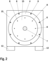
- FIG. 2 shows an exemplary illustration of one embodiment of a drive end of an electric motor according to the present invention.
- the motor frame 13-15 of said electric motor according to the presented embodiment comprises a casing 14 and end plates 13, 15 being attached to said casing 14 at opposite axial ends of the frame.
- a first end plate 15 at a drive end D of the electric motor is shown.
- Said first end plate 15 comprises a bearing shield 4 attached to said first end plate 15 with attachment bolts 6.
- Said first end plate 15 also comprises a number of threaded holes 8 arranged receiving attachment bolts for attaching and connecting an adjustment flange 3 to said first end plate 15 at the drive end D of the electric motor.
- the shaft 7 of the motor is marked with a reference number 7.
- FIG 3 shows an exemplary illustration of one embodiment of an adjustment flange of an electric motor according to the present invention.
- the presented embodiment of an adjustment flange 3 comprises two annular end portions 31, 32 being joined together with a number of axial beams 35, one end of each of said axial beams 35 joining a first annular end portion 31 and another opposite end of each of said axial beams 35 joining a second annular end portion 32.
- Said two annular end portions 31, 32 of said adjustment flange 3 may have different diameters as shown in Figure 3 .
- said two annular end portions 31, 32 of an adjustment flange 30 may have same diameters as depicted in Figure 1 .
- the first annular end portion 31 of said adjustment flange 3 comprises a number of holes 33 arranged for receiving mounting bolts for mounting said adjustment flange 3 to the first end plate 15 at the drive end D of the electric motor.
- the second annular end portion 32 of said adjustment flange 3 comprises a number of holes 34 arranged for receiving mounting bolts for mounting said adjustment flange 3 to the load frame 25.
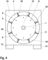
- FIG 4 shows an exemplary illustration of one embodiment of a drive end of an electric motor according to the present invention without an adjustment flange.
- the motor frame of said electric motor 1 according to the present embodiment comprises a casing and end plates being attached to said casing at opposite axial ends of the frame.
- a first end plate 15 at a drive end D of the electric motor 1 is shown.
- Said first end plate 15 comprises a bearing shield 4 attached to said first end plate 15 with attachment bolts 6.
- FIG 4 said embodiment of a drive end of an electric motor according to the present invention is shown without an adjustment flange 3.
- Said first end plate 15 also comprises a number of threaded holes 8 arranged for receiving mounting bolts for mounting an adjustment flange 3 to said first end plate 15 at the drive end D of the electric motor.
- the shaft 7 of the motor is marked with a reference number 7.
- the unsupported motor feet 12 at the drive end D of the electric motor are marked with a reference number 12.
- the electric motor according to the present embodiment comprises at least three threaded adjustment pieces 40 fixed to the bearing shield 4.
- each threaded adjustment piece 40 of said at least three threaded adjustment pieces 40 is fixed to the bearing shield 4 of the electric motor with the help of two fixing screws.
- the presented embodiment comprises eight threaded adjustment pieces 40 fixed to the bearing shield 4.
- each threaded adjustment piece 40 of said at least three threaded adjustment pieces 40 may be welded to the bearing shield 4 of the electric motor.
- each of said threaded adjustment pieces 40 comprises an adjustment screw arranged for adjusting the distance between an adjustment flange 3 and the bearing shield 4 attached to the first end plate 15 at a drive end D of the electric motor 1.
- the adjustment screws of said threaded adjustment pieces 40 are arranged as radial screws for radial adjustment of the adjustment flange 3.
- said radial screws may be arranged with a fine thread pitch for enhancing the adjustment, i.e. a thread pitch of 1,25 mm or less.
- FIG 5 shows an exemplary illustration of one embodiment of a drive end of an electric motor according to the present invention accompanied with an adjustment flange.
- the motor frame of said electric motor according to the present embodiment comprises a casing and end plates being attached to said casing at opposite axial ends of the frame.
- a first end plate 15 at a drive end D of the electric motor is shown.
- Said first end plate 15 comprises a bearing shield 4 attached to said first end plate 15 with attachment bolts 6.
- FIG. 5 said embodiment of a drive end of an electric motor according to the present invention is shown accompanied with an adjustment flange 3.
- Said adjustment flange 3 is mounted to said first end plate 15 at the drive end D of the electric motor with mounting bolts 38.
- Said mounting bolts 38 are used for securing a first annular end portion 31 of said adjustment flange 3 to the first end plate 15 through a number of holes in said first annular end portion 31 to a number of threaded holes 8 in said first end plate 15.
- the shaft 7 of the motor is marked with a reference number 7.
- the unsupported motor feet 12 at the drive end D of the electric motor are marked with a reference number 12.
- the electric motor according to the present embodiment comprises at least three threaded adjustment pieces 40 fixed to the bearing shield 4.
- each threaded adjustment piece 40 of said at least three threaded adjustment pieces 40 is fixed to the bearing shield 4 of the electric motor with the help of two fixing screws.
- the presented embodiment comprises eight threaded adjustment pieces 40 fixed to the bearing shield 4.
- each threaded adjustment piece 40 of said at least three threaded adjustment pieces 40 may be welded to the bearing shield 4 of the electric motor.
- each of said threaded adjustment pieces 40 comprises an adjustment screw arranged for adjusting the distance between an adjustment flange 3 and the bearing shield 4 attached to the first end plate 15 at a drive end D of the electric motor 1.
- the adjustment piece 40 comprises a small block 40 that is fixed to the bearing shield 4 and an adjustment screw through this block 40. The head of the adjustment screw is against the flange.
- the adjustment screws of said threaded adjustment pieces 40 are arranged as radial screws for radial adjustment of the adjustment flange 3.
- the presented embodiment comprises eight threaded adjustment pieces 40 fixed to the bearing shield 4, i.e. one threaded adjustment piece 40 with an adjustment screw for each axial beam 35 of said adjustment flange 3.
- said electric motor comprises four threaded adjustment pieces 40 of which two threaded adjustment pieces 40 are arranged in vertical direction and two threaded adjustment pieces 40 are arranged in horizontal direction.
- each of said threaded adjustment pieces 40 the distance between the adjustment flange 3 and the bearing shield 4 near said threaded adjustment piece 40 can be adjusted.
- said adjustment procedure first the mounting bolts 38 of said adjustment flange 3 are slightly loosened to allow radial movement of the adjustment flange 3. Thereafter one or more threaded adjustment pieces 40 are selected on sides where distance between the adjustment flange 3 and the bearing shield 4 is to be increased.
- each of said selected threaded adjustment pieces 40 are screwed and adjusted so that said adjustment screws first contact a respective axial beam 35 of said adjustment flange 3 and then further move the adjustment flange 3 to an alignment position.
- Figure 6 shows a top view of an embodiment of a threaded adjustment piece of an electric motor according to the present invention.
- a threaded adjustment piece 40 is fixed to the bearing shield 4 of the electric motor with the help of two fixing screws 42, 43.
- a threaded adjustment piece 40 may be welded to the bearing shield 4 of the electric motor.
- a threaded adjustment piece 40 comprises an adjustment screw 41 arranged for adjusting the distance d between the adjustment flange 3 and the bearing shield 4 attached to the first end plate 15 at a drive end D of the electric motor 1.
- the adjustment piece 40 comprises a small block 40 that is fixed to the bearing shield 4 and an adjustment screw 41 through this block 40. The head of the adjustment screw 41 is against the flange.
- the adjustment screws 41 of each of said threaded adjustment pieces 40 are arranged as radial screws for radial adjustment of the adjustment flange 3.
- said radial screws 41 may be arranged with a fine thread pitch for enhancing the adjustment, i.e. a thread pitch of 1,25 mm or less.
- the distance d between the adjustment flange 3 and the bearing shield 4 can be adjusted.
- said adjustment procedure first the mounting bolts 38 of said adjustment flange 3 are slightly loosened to allow radial movement of the adjustment flange 3.
- said adjustment screw 41 of said threaded adjustment piece 40 is screwed and adjusted so that said adjustment screw 41 first contacts a respective axial beam 35 of said adjustment flange 3 and then further moves the adjustment flange 3 so that the distance d between the adjustment flange 3 and the bearing shield 4 increases to an alignment position.
- FIG. 7 shows a side view of an embodiment of a threaded adjustment piece of an electric motor according to the present invention.
- a threaded adjustment piece 40 is fixed to the bearing shield 4 of the electric motor with the help of two fixing screws 42, 43.
- a threaded adjustment piece 40 comprises an adjustment screw 41 arranged for adjusting the distance d between the adjustment flange 3 and the bearing shield 4 attached to the first end plate 15 at a drive end D of the electric motor 1.
- the adjustment screws 41 of each of said threaded adjustment pieces 40 are arranged as radial screws for radial adjustment of the adjustment flange 3.
- said radial screws 41 may be arranged with a fine thread pitch for enhancing the adjustment, i.e. a thread pitch of 1,25 mm or less.
- Figure 8 shows a top view of an embodiment of a threaded adjustment piece of an electric motor according to the present invention.
- a threaded adjustment piece 50 is welded to the bearing shield 4 of the electric motor and a respective contact piece 60 is welded to the adjustment flange 3.
- a threaded adjustment piece 40 comprises an adjustment screw 51 arranged for adjusting the distance d between the adjustment flange 3 and the bearing shield 4 attached to the first end plate 15 at a drive end D of the electric motor 1.
- the adjustment piece 50 comprises a small block 50 that is fixed to the bearing shield 4 and an adjustment screw 51 through this block 50. The head of the adjustment screw 41 is against the flange.
- the adjustment screws 51 of each of said threaded adjustment pieces 50 are arranged as radial screws for radial adjustment of the adjustment flange 3.
- said radial screws 51 may be arranged with a fine thread pitch for enhancing the adjustment, i.e. a thread pitch of 1,25 mm or less.
- the distance d between the adjustment flange 3 and the bearing shield 4 can be adjusted.
- said adjustment procedure first the mounting bolts 38 of said adjustment flange 3 are slightly loosened to allow radial movement of the adjustment flange 3.
- said adjustment screw 51 of said threaded adjustment piece 50 is screwed and adjusted so that said adjustment screw 51 first contacts said respective contact piece 60 in said adjustment flange 3 and then further moves the adjustment flange 3 so that the distance d between the adjustment flange 3 and the bearing shield 4 increases to an alignment position.
- FIG 9 shows an exemplary illustration of another embodiment of a drive end of an electric motor according to the present invention accompanied with an adjustment flange.
- the motor frame of said electric motor according to the present embodiment comprises a casing and end plates being attached to said casing at opposite axial ends of the frame.
- a first end plate 15 at a drive end D of the electric motor is shown.
- Said first end plate 15 comprises a bearing shield 4 attached to said first end plate 15 with attachment bolts 6 and an adjustment flange 3 mounted to said first end plate 15 with mounting bolts 38.
- Said mounting bolts 38 are used for securing a first annular end portion 31 of said adjustment flange 3 to the first end plate 15 through a number of holes 33 in said first annular end portion 31 to a number of threaded holes 8 in said first end plate 15.
- the shaft 7 of the motor is marked with a reference number 7.
- the unsupported motor feet 12 at the drive end D of the electric motor are marked with a reference number 12.
- the electric motor 1 according to the presented another embodiment comprises at least three threaded adjustment pieces 50 welded to the bearing shield 4 and at least three respective contact pieces 60 welded to the adjustment flange 3.
- said electric motor 1 comprises at least three threaded adjustment pieces 50 welded to the adjustment flange 3 and at least three respective contact pieces 60 welded to the bearing shield 4.
- the presented embodiment comprises eight threaded adjustment pieces 50 welded to the bearing shield 4 and eight respective contact pieces 60 welded to the adjustment flange 3.
- each of said threaded adjustment pieces 50 comprises an adjustment screw 51 arranged for adjusting the distance between an adjustment flange 3 and the bearing shield 4 attached to the first end plate 15 at a drive end D of the electric motor 1.
- the adjustment screws 51 of said threaded adjustment pieces 50 are arranged as radial screws 51 for radial adjustment of the adjustment flange 3.
- said radial screws 51 may be arranged with a fine thread pitch for enhancing the adjustment, i.e. a thread pitch of 1,25 mm or less.
- said electric motor comprises four threaded adjustment pieces 50 and four respective contact pieces 60 of which two threaded adjustment pieces 50 and two respective contact pieces 60 are arranged in vertical direction and two threaded adjustment pieces 50 and two respective contact pieces 60 are arranged in horizontal direction.
- each of said threaded adjustment pieces 40 and respective contact pieces 60 the distance between the adjustment flange 3 and the bearing shield 4 near said threaded adjustment piece 50 can be adjusted.
- said adjustment procedure first the mounting bolts 38 of said adjustment flange 3 are slightly loosened to allow radial movement of the adjustment flange 3. Thereafter, one or more threaded adjustment pieces 50 are selected on sides where distance between the adjustment flange 3 and the bearing shield 4 is to be increased.
- adjustment screws 51 of each of said selected threaded adjustment pieces 50 are screwed and adjusted so that said adjustment screws 51 first contact a respective contact piece 60 in said adjustment flange 3 and then further move the adjustment flange 3 to an alignment position. Thereafter, the mounting bolts 38 of said adjustment flange 3 are tightened for securing said adjustment flange 3 to the alignment position.
- FIG. 10 illustrates a flow diagram of an embodiment of a method for aligning a load with an electric motor according to the present invention.
- an adjustment flange 3 is first mounted 71 to said electric motor 1.
- Said adjustment flange 3 is mounted 71 to said first end plate 15 at the drive end D of the electric motor 1 with mounting bolts 38.
- Said mounting bolts 38 are used for securing a first annular end portion 31 of said adjustment flange 3 to the first end plate 15 through a number of holes 33 in said first annular end portion 31 to a number of threaded holes 8 in said first end plate 15.
- a required alignment correction is measured 72 from a shaft 7 of said electric motor 1.
- the measuring 72 may be carried out with the help of a laser based measurement and alignment system.
- the utilized adjustment pieces 40, 50 as well as applied adjustment for each utilized adjustment piece 40, 50 are calculated 73 based on said measured required alignment correction.
- the axial displacement of a screw is proportional to the rotation angle and the screw thread pitch.
- the required rotational angle of an individual screw can be calculated 73 based on said measured required alignment correction i.e. from the required radial displacement of said adjustment flange 3, 30.
- the applied adjustments i.e. the displacements for each adjustment screw 41, 51 in each utilized adjustment piece 40, 50 are calculated 73 by simple trigonometric equations.
- a required rotation angle can be calculated for each adjustment screw 41, 51 based on the angular position of the adjustment screw 41, 51.
- the mounting bolts 38 of said adjustment flange 3 are slightly loosened 74 to allow radial movement of the adjustment flange 3.
- the calculated adjustments are applied 75 in each utilized adjustment piece 40, 50.
- the adjustments are applied 75 i.e. the adjustment screws 41, 51 of each of said utilized threaded adjustment pieces 40, 50 are screwed and adjusted in accordance with said calculated adjustments for moving said adjustment flange 3 radially so that said adjustment screws 41, 51 move the adjustment flange 3 to an alignment position.
- the mounting bolts 38 of said adjustment flange 3 are tightened 76 for securing said adjustment flange 3 to the alignment position.
- said at least three threaded adjustment pieces 40, 50 can be removed from said bearing shield 4 or from said adjustment flange 3.
- the method according to the present invention can be used during the motor manufacturing and system integration.
- An additional advantage of the present invention is that the locking pins are not needed because the adjustment screws locate the adjustment flange properly for long term operation.
- the solution according to the present invention provides an effective solution for aligning the motor with the load in applications where the mounting of the electric motor has to be carried out so that the supporting foundation is available only for the non-drive end of the electric motor.
Landscapes
- Engineering & Computer Science (AREA)
- Power Engineering (AREA)
- Manufacturing & Machinery (AREA)
- Motor Or Generator Frames (AREA)
Abstract
A field of electric motors, such as electric motors and electric generators for industrial applications, and more particularly to an electric motor. The electric motor of the present invention comprises a rotor comprising a shaft and a rotor core supported on the shaft, a stator surrounding the rotor, a motor frame surrounding the stator and comprising a first end plate at a drive end of the electric motor, and a bearing shield attached to the first end plate, wherein a non-drive end of the electric motor is supported by a non-drive end supporting foundation, and a drive end of the electric motor is configured to be mounted together with a load with help of an adjustment flange, and wherein the electric motor further comprises at least three threaded adjustment pieces fixed to the bearing shield or to the adjustment flange, and at least three threaded adjustment screws, each of the adjustment screws configured for being driven through a respective threaded adjustment piece and for moving said adjustment flange radially.
Description
- The present invention relates to the field of electric motors, such as electric motors and electric generators for industrial applications, and more particularly to an electric motor.
- Electric motors are used in industry for different applications, such as electric motors within the transportation industry, within the process and manufacturing industry as well as within the energy industry. An electric motor converts electrical energy into mechanical energy. Most electric motors operate through the interaction of magnetic fields and current-carrying conductors to generate force. Electric motors are found in applications as diverse as industrial applications, small and medium size industrial motors of highly standardized dimensions and characteristics provide convenient mechanical power for industrial uses. Larger electric motors are used for propulsion of ships in ship propulsion unit applications of the marine industry, for pipeline compressors, and for water pumps with ratings in the millions of watts.
- The electric motor comprises a rotor comprising a shaft and a rotor core supported on the shaft, a stator surrounding the rotor, and a motor frame surrounding the stator. The shaft is typically supported with bearing arrangements on both ends of the motor, i.e. on a drive end of the motor and on a non-drive end of the motor. In most applications the motor frame of the electric motor is mounted on a supporting foundation near the load. However, in some applications the mounting of the electric motor has to be carried out so that the supporting foundation is available only for the non-drive end of the electric motor.
- In applications where the supporting foundation is available only for the non-drive end of the electric motor the mounting of said electric motor has to be carried out so that the drive end of the electric motor is supported to the load frame with help of an adapter flange.
- The problem with applications where the support for the electric motor drive end is available only via an adapter flange to the load frame is that the alignment of the motor shaft line with the load shaft line is a very challenging and problematic task. In the alignment of the motor and the load shaft lines, both the load and motor shafts must first be separately well-aligned with respect to the adapter flange and confirmed by the locking pins. Later, the alignment typically has to be corrected when the motor and the load are mounted together at factory facilities or in situ.
- In principle, the well-aligned motor and compressor can be mounted together by the mating adapter flanges without any additional actions. In practice, the alignment adjustment is often needed due to tolerances and system flexibility. For example, the sagging of the motor-load system affects the alignment.
- Furthermore, in large motors, the alignment is affected by the flexibility of the adapter flange and motor frame structures. Thus, at first the alignment of the motor shaft with respect to the adapter flange must be carried out by supporting the motor from the adapter flange and from the motor feet at the non-drive end of the electric motor. The adapter flange is mounted to the drive-end bearing shield. The alignment has to be carried out by moving the adapter flange radially with respect to the bearing shield. As a well-aligned position is reached, locking pins are used to locate permanently the proper position.
- The alignment of whole system is very difficult and problematic because the flange-shield connection that is used for the alignment also carries the weight of the whole system. In this phase, the locking pins must be removed to allow a new alignment position. This system alignment would typically also require the drilling of new pin holes.
- In principle, there are two traditional solutions for the alignment challenge. First, the stiffness of the structures can be increased to reduce deformations, and second, tighter manufacturing tolerances can be applied to reduce alignment error. However, these solutions increase the weight of the components and increase the manufacturing costs.
- There is a demand in the market for an electric motor solution which would allow aligning the motor with the load in applications where the mounting of the electric motor has to be carried out so that the supporting foundation is available only for the non-drive end of the electric motor.
- The object of the invention is to introduce an electric motor, which would provide a solution for aligning the motor with the load in applications where the mounting of the electric motor has to be carried out so that the supporting foundation is available only for the non-drive end of the electric motor. Advantageous embodiments are furthermore presented.
- It is brought forward a new electric motor which comprises: a rotor comprising a shaft and a rotor core supported on the shaft; a stator surrounding the rotor; a motor frame surrounding the stator and comprising a first end plate at a drive end of said electric motor; and a bearing shield attached to said first end plate, wherein a non-drive end of said electric motor is supported by a non-drive end supporting foundation, and a drive end of said electric motor is configured to be mounted together with a load with help of an adjustment flange, and wherein said electric motor further comprises at least three threaded adjustment pieces fixed to said bearing shield or to said adjustment flange; and at least three threaded adjustment screws, each of said adjustment screws configured for being driven through a respective threaded adjustment piece and for moving said adjustment flange radially.
- In a preferred embodiment, said electric motor further comprises an adjustment flange mounted to said first end plate at the drive end of said electric motor with mounting bolts.
- In a preferred embodiment, said at least three threaded adjustment pieces are fixed to said bearing shield or to said adjustment flange with the help of fixing screws.
- In a preferred embodiment, said at least three threaded adjustment pieces are welded to said bearing shield or to said adjustment flange.
- In a preferred embodiment, said at least three threaded adjustment pieces comprise two threaded adjustment pieces arranged in vertical direction and two threaded adjustment pieces arranged in horizontal direction.
- In a preferred embodiment, said at least three threaded adjustment pieces comprise eight threaded adjustment pieces.
- In a preferred embodiment, said at least three threaded adjustment pieces comprise one threaded adjustment piece for each axial beam of said adjustment flange.
- In a preferred embodiment, said at least three threaded adjustment pieces are fixed to said bearing shield, and wherein said electric motor further comprises at least three respective contact pieces fixed to the adjustment flange.
- In a preferred embodiment, said at least three threaded adjustment pieces are fixed to said adjustment flange, and wherein said electric motor further comprises at least three respective contact pieces fixed to said bearing shield.
- In a preferred embodiment, said adjustment screws are arranged as radial screws.
- In a preferred embodiment, said adjustment screws are arranged as radial screws with a fine thread pitch.
- It is brought forward a new method for aligning a load with an electric motor comprising a rotor comprising a shaft and a rotor core supported on the shaft; a stator surrounding the rotor; a motor frame surrounding the stator and including a first end plate at a drive end of said electric motor; and a bearing shield attached to said first end plate, wherein a non-drive end of said electric motor is supported by a non-drive end supporting foundation, and a drive end of said electric motor is configured to be mounted together with a load with help of an adjustment flange, and wherein said electric motor further includes: at least three threaded adjustment pieces fixed to said bearing shield or to said adjustment flange; and at least three threaded adjustment screws, each of said adjustment screws configured for being driven through a respective threaded adjustment piece and for moving said adjustment flange radially, said method comprising: mounting an adjustment flange to said electric motor; measuring required alignment correction from a shaft of said electric motor; calculating applied adjustment for each utilized adjustment piece based on said measured required alignment correction; loosening the mounting bolts of said adjustment flange slightly to allow radial movement of said adjustment flange; adjusting the adjustment screws of each of said utilized threaded adjustment pieces in accordance with said calculated adjustments for moving said adjustment flange radially; and tightening the mounting bolts of said adjustment flange for securing said adjustment flange.
- In a preferred embodiment, said required alignment correction is measured with the help of a laser based measurement and alignment system.
- In a preferred embodiment, in said calculating a required rotational angle for each individual screw is calculated based on said measured required radial displacement of said adjustment flange .
- In a preferred embodiment, said method comprises removing said at least three threaded adjustment pieces from said bearing shield or from said adjustment flange.
- In the following, the present invention will be described in more detail by way of example and with reference to the attached drawings, in which:
-
Figure 1 shows an exemplary installation arrangement of one embodiment of an electric motor according to the present invention. -
Figure 2 shows an exemplary illustration of one embodiment of a drive end of an electric motor according to the present invention. -
Figure 3 shows an exemplary illustration of one embodiment of an adjustment flange of an electric motor according to the present invention. -
Figure 4 shows an exemplary illustration of one embodiment of a drive end of an electric motor according to the present invention without an adjustment flange. -
Figure 5 shows an exemplary illustration of one embodiment of a drive end of an electric motor according to the present invention accompanied with an adjustment flange. -
Figure 6 shows a top view of an embodiment of a threaded adjustment piece of an electric motor according to the present invention. -
Figure 7 shows a side view of an embodiment of a threaded adjustment piece of an electric motor according to the present invention. -
Figure 8 shows a top view of another embodiment of a threaded adjustment piece of an electric motor according to the present invention. -
Figure 9 shows an exemplary illustration of another embodiment of a drive end of an electric motor according to the present invention accompanied with an adjustment flange. -
Figure 10 illustrates a flow diagram of an embodiment of a method for aligning a load with an electric motor according to the present invention. - The foregoing aspects, features and advantages of the invention will be apparent from the drawings and the detailed description related thereto.
- In the following, the invention will be described in greater detail by means of preferred embodiments with reference to the accompanying drawings of
Figures 1 to 10 . - The following embodiments are exemplary. Although the description may refer to "an", "one", or "some" embodiment(s) in several locations, this does not necessarily mean that each such reference is to the same embodiment(s), or that the feature only applies to a single embodiment, for example. Single features of different embodiments may also be combined to provide other embodiments. Generally, all terms and expressions used should be interpreted broadly and they are intended to illustrate, not to restrict, the embodiments. The figures only show components necessary for understanding the various embodiments. The number and/or shape of the various elements, and generally their implementation, could vary from the examples shown in the figures. The application of the various embodiments described herein is not limited to any specific system, but it can be used in connection with various applications where the mounting of the electric motor has to be carried out so that the supporting foundation is available only for the non-drive end of the electric motor.
- The electric motor of the present invention comprises: a rotor comprising a shaft and a rotor core supported on the shaft; a stator surrounding the rotor; a motor frame surrounding the stator and comprising a first end plate at a drive end of said electric motor; and a bearing shield attached to said first end plate, wherein a non-drive end of said electric motor is supported by a non-drive end supporting foundation, and a drive end of said electric motor is configured to be mounted together with a load with help of an adjustment flange, and wherein said electric motor further comprises at least three threaded adjustment pieces fixed to said bearing shield or to said adjustment flange; and at least three threaded adjustment screws, each of said adjustment screws configured for being driven through a respective threaded adjustment piece and for moving said adjustment flange radially.
- When referring to "threaded adjustment pieces", in this application it is meant to comprise any form of small metal block elements comprising a threaded lead-through opening. When referring to "threaded adjustment screws", in this application is meant to comprise any form of threaded screw, threaded bolt or threaded element suited for being driven through a threaded adjustment piece.
-
Figure 1 shows an exemplary installation arrangement of one embodiment of an electric motor according to the present invention. The presented installation arrangement comprises amotor 1, a load 2 and anadjustment flange 30. Saidmotor 1 comprises ashaft 7, a rotor being supported on theshaft 7, a stator surrounding the rotor, a motor frame 13-15 surrounding the stator, and abearing shield 4 attached to a drive end D of the motor frame 13-15. InFigure 1 the non-drive end is marked with a letter N and the drive end is marked with a letter D. - Said motor frame 13-15 comprises a
casing 14 andend plates casing 14 at opposite axial ends of the frame, the shaft being supported with a first bearing arrangement on afirst end plate 15 at a drive end D of the electric motor and with a second bearing arrangement on asecond end plate 13 at a non-drive end N of saidmotor 1. Saidadjustment flange 30 connects the motor frame 13-15 to theframe 25 of said load 2. In the presented installation arrangement theelectric motor 1 has non-driveend supporting foundation 101 available only for the non-drive end N of theelectric motor 1. The load 2 may be a compressor 2. - As presented in
Figure 1 themotor feet 11 at the non-drive end N of theelectric motor 1 are supported by said non-driveend supporting foundation 101. Respectively, themotor feet 12 at the drive end D of the electric motor are unsupported. As presented inFigure 1 the drive end D of the electric motor is supported to the load 2 via anadjustment flange 30, whichadjustment flange 30 connects the frame of saidmotor 1 to theload frame 25. As presented inFigure 1 theload feet 23 of the load 2 are supported by aload supporting foundation 103. In the process of mounting theelectric motor 1 together with the load 2 with help of theadjustment flange 30 theshaft 7 of theelectric motor 1 is first aligned with aload shaft 27 of the load 2 after which theshaft 7 of theelectric motor 1 and theload shaft 27 are coupled together. -
Figure 2 shows an exemplary illustration of one embodiment of a drive end of an electric motor according to the present invention. The motor frame 13-15 of said electric motor according to the presented embodiment comprises acasing 14 andend plates casing 14 at opposite axial ends of the frame. InFigure 2 afirst end plate 15 at a drive end D of the electric motor is shown. Saidfirst end plate 15 comprises abearing shield 4 attached to saidfirst end plate 15 withattachment bolts 6. Saidfirst end plate 15 also comprises a number of threadedholes 8 arranged receiving attachment bolts for attaching and connecting anadjustment flange 3 to saidfirst end plate 15 at the drive end D of the electric motor. Theshaft 7 of the motor is marked with areference number 7. -
Figure 3 shows an exemplary illustration of one embodiment of an adjustment flange of an electric motor according to the present invention. The presented embodiment of anadjustment flange 3 comprises twoannular end portions axial beams 35, one end of each of saidaxial beams 35 joining a firstannular end portion 31 and another opposite end of each of saidaxial beams 35 joining a secondannular end portion 32. Said twoannular end portions adjustment flange 3 may have different diameters as shown inFigure 3 . Alternatively, said twoannular end portions adjustment flange 30 may have same diameters as depicted inFigure 1 . - The first
annular end portion 31 of saidadjustment flange 3 comprises a number ofholes 33 arranged for receiving mounting bolts for mounting saidadjustment flange 3 to thefirst end plate 15 at the drive end D of the electric motor. Respectively, the secondannular end portion 32 of saidadjustment flange 3 comprises a number ofholes 34 arranged for receiving mounting bolts for mounting saidadjustment flange 3 to theload frame 25. -
Figure 4 shows an exemplary illustration of one embodiment of a drive end of an electric motor according to the present invention without an adjustment flange. The motor frame of saidelectric motor 1 according to the present embodiment comprises a casing and end plates being attached to said casing at opposite axial ends of the frame. InFigure 4 afirst end plate 15 at a drive end D of theelectric motor 1 is shown. Saidfirst end plate 15 comprises abearing shield 4 attached to saidfirst end plate 15 withattachment bolts 6. - In
Figure 4 said embodiment of a drive end of an electric motor according to the present invention is shown without anadjustment flange 3. Saidfirst end plate 15 also comprises a number of threadedholes 8 arranged for receiving mounting bolts for mounting anadjustment flange 3 to saidfirst end plate 15 at the drive end D of the electric motor. Theshaft 7 of the motor is marked with areference number 7. Also, theunsupported motor feet 12 at the drive end D of the electric motor are marked with areference number 12. - The electric motor according to the present embodiment comprises at least three threaded
adjustment pieces 40 fixed to thebearing shield 4. In the presented embodiment each threadedadjustment piece 40 of said at least three threadedadjustment pieces 40 is fixed to thebearing shield 4 of the electric motor with the help of two fixing screws. The presented embodiment comprises eight threadedadjustment pieces 40 fixed to thebearing shield 4. In an alternative embodiment each threadedadjustment piece 40 of said at least three threadedadjustment pieces 40 may be welded to thebearing shield 4 of the electric motor. In the presented embodiment each of said threadedadjustment pieces 40 comprises an adjustment screw arranged for adjusting the distance between anadjustment flange 3 and thebearing shield 4 attached to thefirst end plate 15 at a drive end D of theelectric motor 1. The adjustment screws of said threadedadjustment pieces 40 are arranged as radial screws for radial adjustment of theadjustment flange 3. In the presented embodiment said radial screws may be arranged with a fine thread pitch for enhancing the adjustment, i.e. a thread pitch of 1,25 mm or less. -
Figure 5 shows an exemplary illustration of one embodiment of a drive end of an electric motor according to the present invention accompanied with an adjustment flange. The motor frame of said electric motor according to the present embodiment comprises a casing and end plates being attached to said casing at opposite axial ends of the frame. InFigure 4 afirst end plate 15 at a drive end D of the electric motor is shown. Saidfirst end plate 15 comprises abearing shield 4 attached to saidfirst end plate 15 withattachment bolts 6. - In
Figure 5 said embodiment of a drive end of an electric motor according to the present invention is shown accompanied with anadjustment flange 3. Saidadjustment flange 3 is mounted to saidfirst end plate 15 at the drive end D of the electric motor with mountingbolts 38. Said mountingbolts 38 are used for securing a firstannular end portion 31 of saidadjustment flange 3 to thefirst end plate 15 through a number of holes in said firstannular end portion 31 to a number of threadedholes 8 in saidfirst end plate 15. Theshaft 7 of the motor is marked with areference number 7. Also, theunsupported motor feet 12 at the drive end D of the electric motor are marked with areference number 12. - The electric motor according to the present embodiment comprises at least three threaded
adjustment pieces 40 fixed to thebearing shield 4. In the presented embodiment each threadedadjustment piece 40 of said at least three threadedadjustment pieces 40 is fixed to thebearing shield 4 of the electric motor with the help of two fixing screws. The presented embodiment comprises eight threadedadjustment pieces 40 fixed to thebearing shield 4. In an alternative embodiment each threadedadjustment piece 40 of said at least three threadedadjustment pieces 40 may be welded to thebearing shield 4 of the electric motor. In the presented embodiment each of said threadedadjustment pieces 40 comprises an adjustment screw arranged for adjusting the distance between anadjustment flange 3 and thebearing shield 4 attached to thefirst end plate 15 at a drive end D of theelectric motor 1. - The
adjustment piece 40 comprises asmall block 40 that is fixed to thebearing shield 4 and an adjustment screw through thisblock 40. The head of the adjustment screw is against the flange. The adjustment screws of said threadedadjustment pieces 40 are arranged as radial screws for radial adjustment of theadjustment flange 3. The presented embodiment comprises eight threadedadjustment pieces 40 fixed to thebearing shield 4, i.e. one threadedadjustment piece 40 with an adjustment screw for eachaxial beam 35 of saidadjustment flange 3. - In an alternative embodiment said electric motor comprises four threaded
adjustment pieces 40 of which two threadedadjustment pieces 40 are arranged in vertical direction and two threadedadjustment pieces 40 are arranged in horizontal direction. - With the help of each of said threaded
adjustment pieces 40 according to the embodiment the distance between theadjustment flange 3 and thebearing shield 4 near said threadedadjustment piece 40 can be adjusted. In said adjustment procedure first the mountingbolts 38 of saidadjustment flange 3 are slightly loosened to allow radial movement of theadjustment flange 3. Thereafter one or more threadedadjustment pieces 40 are selected on sides where distance between theadjustment flange 3 and thebearing shield 4 is to be increased. - After this the adjustment screws of each of said selected threaded
adjustment pieces 40 are screwed and adjusted so that said adjustment screws first contact a respectiveaxial beam 35 of saidadjustment flange 3 and then further move theadjustment flange 3 to an alignment position. -
Figure 6 shows a top view of an embodiment of a threaded adjustment piece of an electric motor according to the present invention. In the presented embodiment a threadedadjustment piece 40 is fixed to thebearing shield 4 of the electric motor with the help of two fixingscrews adjustment piece 40 may be welded to thebearing shield 4 of the electric motor. In the presented embodiment a threadedadjustment piece 40 comprises anadjustment screw 41 arranged for adjusting the distance d between theadjustment flange 3 and thebearing shield 4 attached to thefirst end plate 15 at a drive end D of theelectric motor 1. Theadjustment piece 40 comprises asmall block 40 that is fixed to thebearing shield 4 and anadjustment screw 41 through thisblock 40. The head of theadjustment screw 41 is against the flange. The adjustment screws 41 of each of said threadedadjustment pieces 40 are arranged as radial screws for radial adjustment of theadjustment flange 3. In the presented embodiment said radial screws 41 may be arranged with a fine thread pitch for enhancing the adjustment, i.e. a thread pitch of 1,25 mm or less. - With the help of the threaded
adjustment piece 40 according to the embodiment the distance d between theadjustment flange 3 and thebearing shield 4 can be adjusted. In said adjustment procedure first the mountingbolts 38 of saidadjustment flange 3 are slightly loosened to allow radial movement of theadjustment flange 3. Thereafter saidadjustment screw 41 of said threadedadjustment piece 40 is screwed and adjusted so that saidadjustment screw 41 first contacts a respectiveaxial beam 35 of saidadjustment flange 3 and then further moves theadjustment flange 3 so that the distance d between theadjustment flange 3 and thebearing shield 4 increases to an alignment position. -
Figure 7 shows a side view of an embodiment of a threaded adjustment piece of an electric motor according to the present invention. In the presented embodiment a threadedadjustment piece 40 is fixed to thebearing shield 4 of the electric motor with the help of two fixingscrews adjustment piece 40 comprises anadjustment screw 41 arranged for adjusting the distance d between theadjustment flange 3 and thebearing shield 4 attached to thefirst end plate 15 at a drive end D of theelectric motor 1. The adjustment screws 41 of each of said threadedadjustment pieces 40 are arranged as radial screws for radial adjustment of theadjustment flange 3. In the presented embodiment said radial screws 41 may be arranged with a fine thread pitch for enhancing the adjustment, i.e. a thread pitch of 1,25 mm or less. -
Figure 8 shows a top view of an embodiment of a threaded adjustment piece of an electric motor according to the present invention. In the presented embodiment a threadedadjustment piece 50 is welded to thebearing shield 4 of the electric motor and arespective contact piece 60 is welded to theadjustment flange 3. In the presented embodiment a threadedadjustment piece 40 comprises anadjustment screw 51 arranged for adjusting the distance d between theadjustment flange 3 and thebearing shield 4 attached to thefirst end plate 15 at a drive end D of theelectric motor 1. Theadjustment piece 50 comprises asmall block 50 that is fixed to thebearing shield 4 and anadjustment screw 51 through thisblock 50. The head of theadjustment screw 41 is against the flange. The adjustment screws 51 of each of said threadedadjustment pieces 50 are arranged as radial screws for radial adjustment of theadjustment flange 3. In the presented embodiment said radial screws 51 may be arranged with a fine thread pitch for enhancing the adjustment, i.e. a thread pitch of 1,25 mm or less. - With the help of the threaded
adjustment piece 50 and therespective contact piece 60 according to the embodiment the distance d between theadjustment flange 3 and thebearing shield 4 can be adjusted. In said adjustment procedure first the mountingbolts 38 of saidadjustment flange 3 are slightly loosened to allow radial movement of theadjustment flange 3. Thereafter saidadjustment screw 51 of said threadedadjustment piece 50 is screwed and adjusted so that saidadjustment screw 51 first contacts saidrespective contact piece 60 in saidadjustment flange 3 and then further moves theadjustment flange 3 so that the distance d between theadjustment flange 3 and thebearing shield 4 increases to an alignment position. -
Figure 9 shows an exemplary illustration of another embodiment of a drive end of an electric motor according to the present invention accompanied with an adjustment flange. The motor frame of said electric motor according to the present embodiment comprises a casing and end plates being attached to said casing at opposite axial ends of the frame. InFigure 9 afirst end plate 15 at a drive end D of the electric motor is shown. Saidfirst end plate 15 comprises abearing shield 4 attached to saidfirst end plate 15 withattachment bolts 6 and anadjustment flange 3 mounted to saidfirst end plate 15 with mountingbolts 38. Said mountingbolts 38 are used for securing a firstannular end portion 31 of saidadjustment flange 3 to thefirst end plate 15 through a number ofholes 33 in said firstannular end portion 31 to a number of threadedholes 8 in saidfirst end plate 15. Theshaft 7 of the motor is marked with areference number 7. Also, theunsupported motor feet 12 at the drive end D of the electric motor are marked with areference number 12. - The
electric motor 1 according to the presented another embodiment comprises at least three threadedadjustment pieces 50 welded to thebearing shield 4 and at least threerespective contact pieces 60 welded to theadjustment flange 3. In an alternative embodiment of the present invention saidelectric motor 1 comprises at least three threadedadjustment pieces 50 welded to theadjustment flange 3 and at least threerespective contact pieces 60 welded to thebearing shield 4. - The presented embodiment comprises eight threaded
adjustment pieces 50 welded to thebearing shield 4 and eightrespective contact pieces 60 welded to theadjustment flange 3. In the presented embodiment each of said threadedadjustment pieces 50 comprises anadjustment screw 51 arranged for adjusting the distance between anadjustment flange 3 and thebearing shield 4 attached to thefirst end plate 15 at a drive end D of theelectric motor 1. The adjustment screws 51 of said threadedadjustment pieces 50 are arranged asradial screws 51 for radial adjustment of theadjustment flange 3. In the presented embodiment said radial screws 51 may be arranged with a fine thread pitch for enhancing the adjustment, i.e. a thread pitch of 1,25 mm or less. - In an alternative embodiment said electric motor comprises four threaded
adjustment pieces 50 and fourrespective contact pieces 60 of which two threadedadjustment pieces 50 and tworespective contact pieces 60 are arranged in vertical direction and two threadedadjustment pieces 50 and tworespective contact pieces 60 are arranged in horizontal direction. - With the help of each of said threaded
adjustment pieces 40 andrespective contact pieces 60 according to the presented another embodiment the distance between theadjustment flange 3 and thebearing shield 4 near said threadedadjustment piece 50 can be adjusted. In said adjustment procedure first the mountingbolts 38 of saidadjustment flange 3 are slightly loosened to allow radial movement of theadjustment flange 3. Thereafter, one or more threadedadjustment pieces 50 are selected on sides where distance between theadjustment flange 3 and thebearing shield 4 is to be increased. - After this the adjustment screws 51 of each of said selected threaded
adjustment pieces 50 are screwed and adjusted so that said adjustment screws 51 first contact arespective contact piece 60 in saidadjustment flange 3 and then further move theadjustment flange 3 to an alignment position. Thereafter, the mountingbolts 38 of saidadjustment flange 3 are tightened for securing saidadjustment flange 3 to the alignment position. -
Figure 10 illustrates a flow diagram of an embodiment of a method for aligning a load with an electric motor according to the present invention. In the method according to the presented embodiment, anadjustment flange 3 is first mounted 71 to saidelectric motor 1. Saidadjustment flange 3 is mounted 71 to saidfirst end plate 15 at the drive end D of theelectric motor 1 with mountingbolts 38. Said mountingbolts 38 are used for securing a firstannular end portion 31 of saidadjustment flange 3 to thefirst end plate 15 through a number ofholes 33 in said firstannular end portion 31 to a number of threadedholes 8 in saidfirst end plate 15. In the presented embodiment, as the next step, a required alignment correction is measured 72 from ashaft 7 of saidelectric motor 1. The measuring 72 may be carried out with the help of a laser based measurement and alignment system. - Thereafter, in the presented embodiment, the utilized
adjustment pieces adjustment piece adjustment flange adjustment screw adjustment piece adjustment screw adjustment screw bolts 38 of saidadjustment flange 3 are slightly loosened 74 to allow radial movement of theadjustment flange 3. - Thereafter, in the presented embodiment, the calculated adjustments are applied 75 in each utilized
adjustment piece adjustment pieces adjustment flange 3 radially so that said adjustment screws 41, 51 move theadjustment flange 3 to an alignment position. In the presented embodiment, as the next step, the mountingbolts 38 of saidadjustment flange 3 are tightened 76 for securing saidadjustment flange 3 to the alignment position. In an alternative embodiment of a method for aligning a load with an electric motor according to the present invention, as a last step, said at least three threadedadjustment pieces bearing shield 4 or from saidadjustment flange 3. - With the help of the present invention there is provided an advanced and effective solution for aligning the motor with the load. The method according to the present invention can be used during the motor manufacturing and system integration. An additional advantage of the present invention is that the locking pins are not needed because the adjustment screws locate the adjustment flange properly for long term operation.
- With the help of the present invention regular stiffness of the structures can be used and normal manufacturing tolerances can be applied with the motor and the load. The alignment solution according to the present invention can be utilized when the motor and the load are mounted together at factory facilities or in situ.
- The solution according to the present invention provides an effective solution for aligning the motor with the load in applications where the mounting of the electric motor has to be carried out so that the supporting foundation is available only for the non-drive end of the electric motor.
- It is to be understood that the above description and the accompanying Figures are only intended to teach the best way known to the inventors to make and use the invention. It will be apparent to a person skilled in the art that the inventive concept can be implemented in various ways. The above-described embodiments of the invention may thus be modified or varied, without departing from the invention, as appreciated by those skilled in the art in light of the above teachings. It is therefore to be understood that the invention and its embodiments are not limited to the examples described above but may vary within the scope of the claims and their equivalents.
Claims (15)
- An electric motor comprising:- a rotor comprising a shaft and a rotor core supported on the shaft;- a stator surrounding the rotor;- a motor frame surrounding the stator and comprising a first end plate at a drive end of said electric motor; and- a bearing shield attached to said first end plate,wherein a non-drive end of said electric motor is supported by a non-drive end supporting foundation, and a drive end of said electric motor is configured to be mounted together with a load with help of an adjustment flange, andwherein said electric motor further comprises:- at least three threaded adjustment pieces fixed to said bearing shield or to said adjustment flange; and- at least three threaded adjustment screws, each of said adjustment screws configured for being driven through a respective threaded adjustment piece and for moving said adjustment flange radially.
- An electric motor according to claim 1, wherein said electric motor further comprises an adjustment flange mounted to said first end plate at the drive end of said electric motor with mounting bolts.
- An electric motor according to claim 1 or to claim 2, wherein said at least three threaded adjustment pieces are fixed to said bearing shield or to said adjustment flange with the help of fixing screws.
- An electric motor according to claim 1 or to claim 2, wherein said at least three threaded adjustment pieces are welded to said bearing shield or to said adjustment flange.
- An electric motor according to any of the claims 1-4, wherein said at least three threaded adjustment pieces comprise two threaded adjustment pieces arranged in vertical direction and two threaded adjustment pieces arranged in horizontal direction.
- An electric motor according to any of the claims 1-4, wherein said at least three threaded adjustment pieces comprise eight threaded adjustment pieces.
- An electric motor according to any of the claims 1-6, wherein said at least three threaded adjustment pieces comprise one threaded adjustment piece for each axial beam of said adjustment flange.
- An electric motor according to any of the claims 1-7, wherein said at least three threaded adjustment pieces are fixed to said bearing shield, and wherein said electric motor further includes at least three respective contact pieces fixed to the adjustment flange.
- An electric motor according to any of the claims 1-8, wherein said at least three threaded adjustment pieces are fixed to said adjustment flange, and wherein said electric motor further includes at least three respective contact pieces fixed to said bearing shield.
- An electric motor according to any of the claims 1-9, wherein said adjustment screws are arranged as radial screws.
- An electric motor according to claim 10, wherein said adjustment screws are arranged as radial screws with a fine thread pitch.
- A method for aligning a load with an electric motor comprising a rotor comprising a shaft and a rotor core supported on the shaft; a stator surrounding the rotor; a motor frame surrounding the stator and including a first end plate at a drive end of said electric motor; and a bearing shield attached to said first end plate, wherein a non-drive end of said electric motor is supported by a non-drive end supporting foundation, and a drive end of said electric motor is configured to be mounted together with a load with help of an adjustment flange, and wherein said electric motor further includes: at least three threaded adjustment pieces fixed to said bearing shield or to said adjustment flange; and at least three threaded adjustment screws, each of said adjustment screws configured for being driven through a respective threaded adjustment piece and for moving said adjustment flange radially, said method comprising:- mounting an adjustment flange to said electric motor;- measuring required alignment correction from a shaft of said electric motor;- calculating applied adjustment for each utilized adjustment piece based on said measured required alignment correction;- loosening the mounting bolts of said adjustment flange slightly to allow radial movement of said adjustment flange;- adjusting the adjustment screws of each of said utilized threaded adjustment pieces in accordance with said calculated adjustments for moving said adjustment flange radially; and- tightening the mounting bolts of said adjustment flange for securing said adjustment flange.
- A method according to claim 12, wherein said required alignment correction is measured with the help of a laser-based measurement and alignment system.
- A method according to claim 12 or to claim 13, wherein in said calculating a required rotational angle for each individual screw is calculated based on said measured required radial displacement of said adjustment flange.
- A method according to any of the claims 12-14, wherein said method comprises:- removing said at least three threaded adjustment pieces from said bearing shield or from said adjustment flange.
Applications Claiming Priority (1)
| Application Number | Priority Date | Filing Date | Title |
|---|---|---|---|
| US18/503,887 US20250149952A1 (en) | 2023-11-07 | 2023-11-07 | Electric motor |
Publications (1)
| Publication Number | Publication Date |
|---|---|
| EP4554065A1 true EP4554065A1 (en) | 2025-05-14 |
Family
ID=93432196
Family Applications (1)
| Application Number | Title | Priority Date | Filing Date |
|---|---|---|---|
| EP24211041.9A Pending EP4554065A1 (en) | 2023-11-07 | 2024-11-06 | Electric motor |
Country Status (3)
| Country | Link |
|---|---|
| US (1) | US20250149952A1 (en) |
| EP (1) | EP4554065A1 (en) |
| CN (1) | CN119966152A (en) |
Families Citing this family (1)
| Publication number | Priority date | Publication date | Assignee | Title |
|---|---|---|---|---|
| USD1098018S1 (en) * | 2022-12-30 | 2025-10-14 | Abb Schweiz Ag | Motor |
Citations (3)
| Publication number | Priority date | Publication date | Assignee | Title |
|---|---|---|---|---|
| GB1450031A (en) * | 1972-12-23 | 1976-09-22 | Eda Overseas Ltd | Electric induction drive assemblies |
| US5258675A (en) * | 1991-10-15 | 1993-11-02 | Marathon Electric Manufacturing Corporation | Mount apparatus for rotatable apparatus coupled to a rotating drive unit |
| WO2011051996A1 (en) * | 2009-10-26 | 2011-05-05 | 株式会社日立製作所 | Permanent magnet dynamo electric machine and permanent magnet dynamo electric machine system for vehicle |
Family Cites Families (10)
| Publication number | Priority date | Publication date | Assignee | Title |
|---|---|---|---|---|
| US5281878A (en) * | 1992-08-27 | 1994-01-25 | Schaeffer George L | Adaptor for hydraulic power tilt/trim reservoirs |
| US6547208B2 (en) * | 2000-12-27 | 2003-04-15 | Delphi Technologies, Inc. | Motor mounting assembly |
| US8700239B2 (en) * | 2007-01-16 | 2014-04-15 | Charles Hampton Perry | Machine for augmentation, storage, and conservation of vehicle motive energy |
| TW201319394A (en) * | 2011-11-07 | 2013-05-16 | Assoma Inc | Improved structure of corrosion-protection housing of permanent magnet canned pump |
| US9948159B2 (en) * | 2013-02-12 | 2018-04-17 | Nissan Motor Co., Ltd. | Stator supporting structure for rotating electrical machine and rotating electrical machine including the same |
| DE102013208536A1 (en) * | 2013-05-08 | 2014-11-13 | Ksb Aktiengesellschaft | pump assembly |
| GB201512264D0 (en) * | 2015-07-14 | 2015-08-19 | Cummins Generator Technologies | Adaptor for generator |
| JP2019180204A (en) * | 2018-03-30 | 2019-10-17 | 日本電産サーボ株式会社 | motor |
| EP4037158B1 (en) * | 2021-02-02 | 2025-07-30 | Black & Decker, Inc. | Brushless motor including a nested bearing bridge |
| TWI810731B (en) * | 2021-12-01 | 2023-08-01 | 車王電子股份有限公司 | motor unit |
-
2023
- 2023-11-07 US US18/503,887 patent/US20250149952A1/en active Pending
-
2024
- 2024-11-04 CN CN202411560399.9A patent/CN119966152A/en active Pending
- 2024-11-06 EP EP24211041.9A patent/EP4554065A1/en active Pending
Patent Citations (3)
| Publication number | Priority date | Publication date | Assignee | Title |
|---|---|---|---|---|
| GB1450031A (en) * | 1972-12-23 | 1976-09-22 | Eda Overseas Ltd | Electric induction drive assemblies |
| US5258675A (en) * | 1991-10-15 | 1993-11-02 | Marathon Electric Manufacturing Corporation | Mount apparatus for rotatable apparatus coupled to a rotating drive unit |
| WO2011051996A1 (en) * | 2009-10-26 | 2011-05-05 | 株式会社日立製作所 | Permanent magnet dynamo electric machine and permanent magnet dynamo electric machine system for vehicle |
Also Published As
| Publication number | Publication date |
|---|---|
| CN119966152A (en) | 2025-05-09 |
| US20250149952A1 (en) | 2025-05-08 |
Similar Documents
| Publication | Publication Date | Title |
|---|---|---|
| CN101521414B (en) | Arrangement for a direct drive generator, direct drive generator, wind turbine and method for the assembly of a generator | |
| EP4554065A1 (en) | Electric motor | |
| CN101459354B (en) | Direct drive generator and wind turbine | |
| US8089175B2 (en) | Direct drive generator and wind turbine | |
| AU2010201562B2 (en) | Wind turbine generator and maintenance method thereof | |
| KR101799354B1 (en) | Wind power generator and wind power generater system | |
| US10454324B2 (en) | Dynamo-electrical machine with segmented stator structure and/or rotor structure | |
| EP1173915A1 (en) | Generator for a windmill, stator module for use in such a generator and use of such a generator | |
| US20120227536A1 (en) | Sectioned tuning ring for rotating body | |
| CN110635585B (en) | Stator assembly, generator and wind turbine for generating electrical power | |
| EP3538759A1 (en) | Standardized platform arrangement of a wind turbine | |
| US12368334B2 (en) | Rotor of motor, method for maintaining rotor of motor, motor and wind-power electric generator set | |
| US10871147B2 (en) | Wind turbine apparatuses | |
| US11777345B2 (en) | Securing of stator segments | |
| US11208983B2 (en) | Wind turbine pitch actuator mounting structure | |
| CN112166249A (en) | Wind turbine power system connection | |
| US20210102529A1 (en) | Busbar arrangement for wind turbine generator | |
| KR102535350B1 (en) | Apparatus for reducing vibration for encoder of generator | |
| US20230091420A1 (en) | Stator for a generator of a wind turbine, generator of a wind turbine, and wind turbine | |
| CN114313571B (en) | Support fixture and method for assembling an electric motor module | |
| EP4568069A1 (en) | Rotor connection to shaft for axial flux motor | |
| KR100790705B1 (en) | Rotors of permanent magnet motors and generators | |
| CN120462612A (en) | A detachable shaftless rim propeller |
Legal Events
| Date | Code | Title | Description |
|---|---|---|---|
| PUAI | Public reference made under article 153(3) epc to a published international application that has entered the european phase |
Free format text: ORIGINAL CODE: 0009012 |
|
| STAA | Information on the status of an ep patent application or granted ep patent |
Free format text: STATUS: THE APPLICATION HAS BEEN PUBLISHED |
|
| AK | Designated contracting states |
Kind code of ref document: A1 Designated state(s): AL AT BE BG CH CY CZ DE DK EE ES FI FR GB GR HR HU IE IS IT LI LT LU LV MC ME MK MT NL NO PL PT RO RS SE SI SK SM TR |
|
| STAA | Information on the status of an ep patent application or granted ep patent |
Free format text: STATUS: REQUEST FOR EXAMINATION WAS MADE |
|
| 17P | Request for examination filed |
Effective date: 20251014 |