EP4554053A1 - Stator assembly cooling method - Google Patents
Stator assembly cooling method Download PDFInfo
- Publication number
- EP4554053A1 EP4554053A1 EP24211246.4A EP24211246A EP4554053A1 EP 4554053 A1 EP4554053 A1 EP 4554053A1 EP 24211246 A EP24211246 A EP 24211246A EP 4554053 A1 EP4554053 A1 EP 4554053A1
- Authority
- EP
- European Patent Office
- Prior art keywords
- stator core
- fin
- axial length
- annular
- teeth
- Prior art date
- Legal status (The legal status is an assumption and is not a legal conclusion. Google has not performed a legal analysis and makes no representation as to the accuracy of the status listed.)
- Pending
Links
Images





Classifications
-
- H—ELECTRICITY
- H02—GENERATION; CONVERSION OR DISTRIBUTION OF ELECTRIC POWER
- H02K—DYNAMO-ELECTRIC MACHINES
- H02K1/00—Details of the magnetic circuit
- H02K1/06—Details of the magnetic circuit characterised by the shape, form or construction
- H02K1/12—Stationary parts of the magnetic circuit
- H02K1/20—Stationary parts of the magnetic circuit with channels or ducts for flow of cooling medium
-
- H—ELECTRICITY
- H02—GENERATION; CONVERSION OR DISTRIBUTION OF ELECTRIC POWER
- H02K—DYNAMO-ELECTRIC MACHINES
- H02K1/00—Details of the magnetic circuit
- H02K1/06—Details of the magnetic circuit characterised by the shape, form or construction
- H02K1/22—Rotating parts of the magnetic circuit
- H02K1/27—Rotor cores with permanent magnets
- H02K1/2706—Inner rotors
- H02K1/272—Inner rotors the magnetisation axis of the magnets being perpendicular to the rotor axis
- H02K1/274—Inner rotors the magnetisation axis of the magnets being perpendicular to the rotor axis the rotor consisting of two or more circumferentially positioned magnets
- H02K1/2753—Inner rotors the magnetisation axis of the magnets being perpendicular to the rotor axis the rotor consisting of two or more circumferentially positioned magnets the rotor consisting of magnets or groups of magnets arranged with alternating polarity
- H02K1/278—Surface mounted magnets; Inset magnets
-
- H—ELECTRICITY
- H02—GENERATION; CONVERSION OR DISTRIBUTION OF ELECTRIC POWER
- H02K—DYNAMO-ELECTRIC MACHINES
- H02K21/00—Synchronous motors having permanent magnets; Synchronous generators having permanent magnets
- H02K21/12—Synchronous motors having permanent magnets; Synchronous generators having permanent magnets with stationary armatures and rotating magnets
- H02K21/14—Synchronous motors having permanent magnets; Synchronous generators having permanent magnets with stationary armatures and rotating magnets with magnets rotating within the armatures
Definitions
- stator assemblies and, more specifically, to a stator assembly with a cooling arrangement.
- a rotor in a motor, can be rotatable disposed within a bore defined through a stator or about an exterior of the stator.
- the rotor can be a shaft with a circular outer diameter that is equipped with a series of magnetic materials.
- the stator has a hub and a series of teeth extending radially inwardly from the hub toward the rotor. Windings made of conductive material are wound around each of the teeth. An air gap is provided between the rotor and the stator. When current is applied to the windings, a resultant magnetic flux interacts with the magnetic materials of the rotor to drive rotations of the rotor about its longitudinal axis.
- the teeth of the stator extend radially outwardly but the operation of the motor is generally similar.
- the motor described above relies on current being applied to the windings, it is often necessary for the motor to be cooled. In many cases, this cooling is partially achieved by the motor being configured as an air-cooled motor but it is often the case that air-cooled motors are not adequately cooled. When this happens, the air-cooled motors suffer from reduced reliability due to insulation breakdown from routine exposure to excessive temperatures.
- a stator core includes laminations disposed in a laminated arrangement to form a stator core body having an axial length extending in a lamination dimension.
- the stator core body includes an annular portion extending along the axial length, teeth extending radially from the annular portion and along the axial length and fins. Each tooth is formed to define one or more holes running along the axial length.
- the fins extend circumferentially across each of the one or more holes.
- each fin is split at a mid-point thereof.
- each fin is offset from an opposite fin.
- one or more turbulators are disposed on one or more fin.
- each fin extends continuously along the axial length.
- each fin is segmented along the axial length.
- each fin has a concave surface facing incoming coolant flow.
- a stator core includes laminations disposed in a laminated arrangement to form a stator core body having an axial length extending in a lamination dimension.
- the stator core body includes an annular ring portion extending along the axial length, teeth extending radially inwardly from the annular ring portion and along the axial length and fins.
- Each tooth is formed to define one or more holes running along the axial length.
- the fins extend circumferentially across each of the one or more holes.
- each fin extends across an entirety of the corresponding hole.
- each fin is split at a mid-point thereof.
- each fin is offset from an opposite fin.
- one or more turbulators are disposed on one or more fin.
- each fin extends continuously along the axial length.
- each fin is segmented along the axial length.
- each fin has a concave surface facing incoming coolant flow.
- a motor includes laminations disposed in a laminated arrangement to form a stator core body having an axial length extending in a lamination dimension.
- the stator core body includes an annular ring portion extending along the axial length teeth extending radially inwardly from the annular ring portion and along the axial length and fins.
- Each tooth is formed to define one or more holes running along the axial length.
- the fins extend circumferentially across each of the one or more holes.
- the motor further includes windings wound around the teeth and a rotor, which is drivable to rotate about a longitudinal axis thereof by current being applied to the windings.
- the laminations include iron.
- the one or more holes are receptive of a cooling air flow whereby the cooling air flow thermally interacts with the fins.
- one of the annular portion is an annular ring portion
- the teeth extend radially inwardly from an inner diameter of the annular ring portion and the rotor is rotatable within the stator core body and the annular portion is an annular cylinder portion, the teeth extend radially outwardly from an outer diameter of the annular cylinder portion and the rotor is rotatable about the stator core body.
- Electromagnetic losses generated within the stator assembly of rotating machinery contribute to heat and increasing temperatures. If temperatures within the assembly become too high, premature material failures can occur, particularly in the stator slot insulation between the stator copper winding and stator core.
- Existing methods to mitigate this problem include, but are not limited to, cooling fluid being flown across the outer diameter of the stator core, cooling fluid being flown through the gap between the stator and rotor, oil being sprayed onto stator copper winding end turns and stator slot insulation with high thermal conductivity. It has been found, however, that with increasing power densities of electric rotating machinery, current cooling technologies and methods are limited in their ability to adequately cool the hottest spots in these products.
- a stator of electric rotating machinery is provided with integrated fluid cooling channels with fins manufactured into the stator core to maximize the surface area available for convective heat transfer.
- the fins of the integrated cooling channels can be circumferentially arranged or provided as offset pins.
- a motor 101 includes laminations 110 (see FIG. 2 ) that are disposed in a laminated arrangement to form a stator core body 120.
- the laminations 110 can include iron or other similar elements and alloys thereof.
- the motor 101 further includes windings 130 and a rotor 140.
- the stator core body 120 has an axial length AL (see FIG. 2 ) extending in a lamination dimension and includes an annular portion 121 and teeth 122.
- the annular portion 121 extends along the axial length AL.
- the teeth 122 extend radially from the annular portion 121 and along the axial length AL.
- Each tooth 122 has a trapezoidal shape 123 and is formed to define one or more triangular holes 124 running along the axial length AL.
- the one or more triangular holes 124 can be receptive of a cooling airflow 150.
- Each of the one or more triangular holes 124 thus acts as a cooling duct located in a root of the corresponding tooth 122 and serves to remove self-generated heat from the windings 130 and the stator core body 120.
- a flux path down the tooth 122 is not affected by the presence of the one or more triangular holes 124.
- the teeth 122 are all substantially a same shape and size.
- the one or more triangular holes 124 are all substantially a same shape and size.
- the stator core body 120 can be formed about the rotor 140.
- the annular portion 121 is an annular ring portion 125 and the teeth 122 extend radially inwardly from an inner diameter of the annular ring portion 125.
- the radially inward ends of the teeth 122 form a stator bore.
- the windings 130 are wound around the teeth 122 and are thus arranged in slots 126 between neighboring teeth 122.
- the windings 130 are configured to carry current applied thereto.
- the rotor 140 can be provided as a shaft having a rotational axis RA extending along a central longitudinal axis thereof and includes magnetic elements arrayed on an outer surface thereof.
- the rotor 140 is thus drivable to rotate within the stator bore of the stator core body 120 by magnetic flux generated by current being applied to the windings 130. As noted above, this magnetic flux extends axially through the teeth 122 and is not affected by the presence of the one or more triangular holes 124.
- multiple windings 130 can be arranged along a radial dimension between neighboring teeth 122.
- the trapezoidal shape of the teeth 122 allow for the formation of the slots 126 to have substantially rectangular shapes and the windings 130 in each slot 126 between neighboring teeth 122 can have a substantially uniform width W along the radial dimension.
- each tooth 122 has a first wide portion 127 at its root near or at the annular ring portion 125, a first narrow portion 128 remote from the root and sidewalls 129 extending between the first wide portion 127 and the first narrow portion 128.
- each of the one or more triangular holes 124 defined by each tooth 122 has a second wide portion 1247 corresponding with the first wide portion 127, a second narrow portion 1248 corresponding with the first narrow portion 128 and sidewalls 1249 that are parallel with the sidewalls 129.
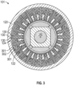
- the one or more triangular holes 124 in each tooth 122 is a pair of triangular holes 301 bisected by a radially oriented member 302 of the stator core body 120.
- a surface area of the pair of triangular holes 301 and the radially oriented member 302 is maximized to provide for relatively high thermal communication in the stator core body 120.
- a flux path extending axially along each tooth 122 is not affected by the presence of the pair of triangular holes 301 or the radially oriented member 302.
- the one or more triangular holes 120 in each tooth 122 is a single triangular hole 401.
- the single triangular hole 401 has a radial length RL H which exceeds half a radial length RL CT of the corresponding tooth 122.
- a triangular cooling duct area provided by each single triangular hole 401 is maximized to provide very low pressure drop across the stator core body 120.
- a flux path extending axially along each tooth 122 is not affected by the presence of the single triangular hole 401.
- the rotor 140 can be formed about the stator core body 120.
- the annular portion 121 is an annular cylinder portion 501 and the teeth 122 extend radially outwardly from an outer diameter of the annular cylinder portion 501.
- the windings 130 are wound around the teeth 122 and are thus arranged in slots 126 between neighboring teeth 122.
- the windings 130 are configured to carry current applied thereto.
- the rotor 140 can be provided as a cylinder 502 having a rotational axis RA extending along a central longitudinal axis of the stator core body 120 and includes magnetic elements arrayed on an interior surface thereof.
- the rotor 140 is thus drivable to rotate about the stator core body 120 by magnetic flux generated by current being applied to the windings 130. As noted above, this magnetic flux extends axially through the teeth 122 and is not affected by the presence of the one or more triangular holes 124.
- FIGS. 1 and 2 , 3, 4 and 5 are described separately, it is to be understood that they are interchangeable.
- the one or more triangular holes 124 of FIG. 5 can be provided as pairs of triangular holes as in FIG. 3 or as single triangular holes as in FIG. 4 .
- the various embodiments of FIGS. 1 and 2 , 3, 4 and 5 can be used in combination with one another.
- the pairs of triangular holes of FIG. 3 and the single triangular holes of FIG. 4 can be interspersed throughout the configurations of FIGS. 1 and 5 .
- embodiments similar to those described above with reference to FIGS. 1-4 and with reference to FIG. 5 can include circumferential fins as described below.
- the following description will relate generally to the above-described embodiments of FIGS. 1 and 4 .
- this is not meant to otherwise limit the scope of the application or the claims in any way and that the following description is applicable to each above-described embodiment without undue experimentation by a person of ordinary skill in the art.
- a motor 601 is provided and includes laminations (see laminations 110 in FIG. 2 ) that are disposed in a laminated arrangement to form a stator core body 620.
- the laminations can include iron or other similar elements and alloys thereof.
- the motor 601 further includes windings 630 and a rotor 640.
- the stator core body 620 has an axial length (see axial length AL in FIG. 2 ) extending in a lamination dimension and includes an annular portion 621 and teeth 622.
- the annular portion 621 extends along the axial length AL.
- the teeth 622 extend radially from the annular portion 621 and along the axial length AL.
- Each tooth 622 has a trapezoidal shape 623 and is formed to define one or more holes 624 running along the axial length AL.
- the one or more holes 624 can be receptive of a cooling airflow (see cooling airflow 150 in FIG. 2 ).
- Each of the one or more holes 624 thus acts as a cooling duct located in a root of the corresponding tooth 622 and serves to remove self-generated heat from the windings 630 and the stator core body 620.
- a flux path down the tooth 622 is not affected by the presence of the one or more holes 624.
- the stator core body 620 can be formed about the rotor 640.
- the annular portion 621 is an annular ring portion 625 and the teeth 622 extend radially inwardly from an inner diameter of the annular ring portion 625.
- the radially inward ends of the teeth 622 form a stator bore.
- the windings 630 are wound around the teeth 622 and are thus arranged in slots 626 between neighboring teeth 622.
- the windings 630 are configured to carry current applied thereto.
- the rotor 640 can be provided as a shaft having a rotational axis RA extending along a central longitudinal axis thereof and includes magnetic elements arrayed on an outer surface thereof.
- the rotor 640 is thus drivable to rotate within the stator bore of the stator core body 620 by magnetic flux generated by current being applied to the windings 630. As noted above, this magnetic flux extends axially through the teeth 622 and is not affected by the presence of the one or more triangular holes 624.
- multiple windings 630 can be arranged along a radial dimension between neighboring teeth 622.
- the trapezoidal shape of the teeth 622 allow for the formation of the slots 626 to have substantially rectangular shapes and the windings 630 in each slot 626 between neighboring teeth 622 can have a substantially uniform width W along the radial dimension.
- each tooth 622 has a first wide portion 627 at its root near or at the annular ring portion 625, a first narrow portion 628 remote from the root and sidewalls 629 extending between the first wide portion 627 and the first narrow portion 628.
- each of the one or more holes 624 defined by each tooth 622 has a second wide portion 6247 corresponding with the first wide portion 627, a second narrow portion 6248 corresponding with the first narrow portion 628 and sidewalls 6249 that are parallel with the sidewalls 629.
- the stator core body 620 can further include fins 701.
- the fins 701 extend circumferentially across each of the one or more holes 624 to define sub-cooling ducts 702 that have more total surface area and thus more cooling effect than if the one or more holes 624 were empty.
- each fin 701 can extend across an entirety of a local span of the corresponding hole 624.
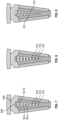
- each fin 701 can be split at a mid-point thereof (see FIG. 8 ), each fin 701 can be offset from an opposite fin 701 (see FIG. 9 ) and/or each fin 701 can include one or more turbulators 1001 (see FIG. 10 ).
- the distal ends of the fins 701 provide for additional surface area for cooling effects beyond the increased surface area of the fins 701 of FIG. 7 and minimize circulating currents being generated in the stator core.
- the turbulators 1001 provide for additional surface area for cooling effects and also create turbulence in cooling flows that can also lead to greater cooling effects.
- each fin 701 can extend continuously along the axial length AL of the stator core body 620 (see FIG. 11A ), each fin 701 can be segmented into fin sections 1101 along the axial length AL (see FIG. 11B ) and, in the case of each fin 701 being segmented into the fin sections 1101, each fin section 1101 can have a concave surface 1102 facing incoming coolant flow to create vortices that can improve cooling effects.
- Additive manufacturing and three-dimensional (3D) printing can be employed to form the fins 701 described herein, especially in cases where fin 701 size is relatively small and/or where detailed embodiments are small and may require unique formations.
- a stator core body of a rotating electric machine that has circumferential fins extending across holes defining cooling paths. These fins increase surface area for thermal interactions and thereby increase cooling effects beyond what is available with the holes alone. This increased cooling effect improves the operation of the stator core body. Also, the split nature of the fins minimizes circulating currents being generated in the stator core.
Landscapes
- Engineering & Computer Science (AREA)
- Power Engineering (AREA)
- Iron Core Of Rotating Electric Machines (AREA)
Abstract
A stator core is provided and includes laminations (110) disposed in a laminated arrangement to form a stator core body (120) having an axial length extending in a lamination dimension. The stator core body includes an annular portion (121) extending along the axial length, teeth (122) extending radially from the annular portion and along the axial length and fins (701). Each tooth is formed to define one or more holes (124) running along the axial length. The fins extend circumferentially across each of the one or more holes.
Description
- The following description relates to stator assemblies and, more specifically, to a stator assembly with a cooling arrangement.
- In a motor, a rotor can be rotatable disposed within a bore defined through a stator or about an exterior of the stator. In the former case, the rotor can be a shaft with a circular outer diameter that is equipped with a series of magnetic materials. The stator has a hub and a series of teeth extending radially inwardly from the hub toward the rotor. Windings made of conductive material are wound around each of the teeth. An air gap is provided between the rotor and the stator. When current is applied to the windings, a resultant magnetic flux interacts with the magnetic materials of the rotor to drive rotations of the rotor about its longitudinal axis. In the case where the rotor is disposed about an exterior of the stator, the teeth of the stator extend radially outwardly but the operation of the motor is generally similar.
- Since the motor described above relies on current being applied to the windings, it is often necessary for the motor to be cooled. In many cases, this cooling is partially achieved by the motor being configured as an air-cooled motor but it is often the case that air-cooled motors are not adequately cooled. When this happens, the air-cooled motors suffer from reduced reliability due to insulation breakdown from routine exposure to excessive temperatures.
- Therefore, a need exists for a stator assembly with a new cooling arrangement.
- According to an aspect of the invention, a stator core is provided and includes laminations disposed in a laminated arrangement to form a stator core body having an axial length extending in a lamination dimension. The stator core body includes an annular portion extending along the axial length, teeth extending radially from the annular portion and along the axial length and fins. Each tooth is formed to define one or more holes running along the axial length. The fins extend circumferentially across each of the one or more holes.
- In embodiments, each fin extends across an entirety of the corresponding hole.
- In embodiments, each fin is split at a mid-point thereof.
- In embodiments, each fin is offset from an opposite fin.
- In embodiments, one or more turbulators are disposed on one or more fin.
- In embodiments, each fin extends continuously along the axial length.
- In embodiments, each fin is segmented along the axial length.
- In embodiments, each fin has a concave surface facing incoming coolant flow.
- According to an aspect of the invention, a stator core is provided and includes laminations disposed in a laminated arrangement to form a stator core body having an axial length extending in a lamination dimension. The stator core body includes an annular ring portion extending along the axial length, teeth extending radially inwardly from the annular ring portion and along the axial length and fins. Each tooth is formed to define one or more holes running along the axial length. The fins extend circumferentially across each of the one or more holes.
- In embodiments, each fin extends across an entirety of the corresponding hole.
- In embodiments, each fin is split at a mid-point thereof.
- In embodiments, each fin is offset from an opposite fin.
- In embodiments, one or more turbulators are disposed on one or more fin.
- In embodiments, each fin extends continuously along the axial length.
- In embodiments, each fin is segmented along the axial length.
- In embodiments, each fin has a concave surface facing incoming coolant flow.
- According to an aspect of the invention, a motor is provided and includes laminations disposed in a laminated arrangement to form a stator core body having an axial length extending in a lamination dimension. The stator core body includes an annular ring portion extending along the axial length teeth extending radially inwardly from the annular ring portion and along the axial length and fins. Each tooth is formed to define one or more holes running along the axial length. The fins extend circumferentially across each of the one or more holes. The motor further includes windings wound around the teeth and a rotor, which is drivable to rotate about a longitudinal axis thereof by current being applied to the windings.
- In embodiments, the laminations include iron.
- In embodiments, the one or more holes are receptive of a cooling air flow whereby the cooling air flow thermally interacts with the fins.
- In embodiments, one of the annular portion is an annular ring portion, the teeth extend radially inwardly from an inner diameter of the annular ring portion and the rotor is rotatable within the stator core body and the annular portion is an annular cylinder portion, the teeth extend radially outwardly from an outer diameter of the annular cylinder portion and the rotor is rotatable about the stator core body.
- These and other advantages and features will become more apparent from the following description taken in conjunction with the drawings.
- The subject matter, which is regarded as the disclosure, is particularly pointed out and distinctly claimed in the claims at the conclusion of the specification. The foregoing and other features and advantages of the disclosure are apparent from the following detailed description taken in conjunction with the accompanying drawings in which:
-
FIG. 1 is an axial view of a motor with an inner rotor and an outer stator core, where the outer stator core has trapezoidal teeth defining triangular cooling holes between neighboring windings in accordance with embodiments; -
FIG. 2 is a side view of the motor ofFIG. 1 in accordance with embodiments; -
FIG. 3 is an axial view of a motor with an inner rotor and an outer stator core, where the outer stator core has trapezoidal teeth defining multiple triangular cooling holes between neighboring windings in accordance with embodiments; -
FIG. 4 is an axial view of a motor with an inner rotor and an outer stator core, where the outer stator core has trapezoidal teeth defining triangular cooling holes of relatively large dimensions between neighboring windings in accordance with embodiments; -
FIG. 5 is an axial view of a motor with an outer rotor and an inner stator core, where the inner stator core has trapezoidal teeth defining triangular cooling holes between neighboring windings in accordance with embodiments; -
FIG. 6 is an axial view of a motor with an inner rotor and an outer stator core, where the outer stator core has teeth defining cooling holes with circumferential fins between neighboring windings in accordance with embodiments; -
FIG. 7 is an enlarged view of a cooling hole and circumferential fins ofFIG. 6 taken from within line 70-70 in accordance with embodiments; -
FIG. 8 is an enlarged view of split circumferential fins ofFIG. 7 in accordance with embodiments; -
FIG. 9 is an enlarged view of split and offset circumferential fins ofFIG. 7 in accordance with embodiments; -
FIG. 10 is an enlarged view of a circumferential fin ofFIG. 7 taken from within line 10-10 in accordance with embodiments; and -
FIGS. 11A, 11B and 11C are cross-sectional views of a circumferential fin ofFIG. 7 taken along line 11-11 in accordance with embodiments. - These and other advantages and features will become more apparent from the following description taken in conjunction with the drawings.
- Electromagnetic losses generated within the stator assembly of rotating machinery (generators, motors) contribute to heat and increasing temperatures. If temperatures within the assembly become too high, premature material failures can occur, particularly in the stator slot insulation between the stator copper winding and stator core. Existing methods to mitigate this problem include, but are not limited to, cooling fluid being flown across the outer diameter of the stator core, cooling fluid being flown through the gap between the stator and rotor, oil being sprayed onto stator copper winding end turns and stator slot insulation with high thermal conductivity. It has been found, however, that with increasing power densities of electric rotating machinery, current cooling technologies and methods are limited in their ability to adequately cool the hottest spots in these products.
- Thus, as will be described below, a stator of electric rotating machinery is provided with integrated fluid cooling channels with fins manufactured into the stator core to maximize the surface area available for convective heat transfer. The fins of the integrated cooling channels can be circumferentially arranged or provided as offset pins.
- With reference to
FIGS. 1 and2 , amotor 101 is provided and includes laminations 110 (seeFIG. 2 ) that are disposed in a laminated arrangement to form astator core body 120. Thelaminations 110 can include iron or other similar elements and alloys thereof. Themotor 101 further includeswindings 130 and arotor 140. Thestator core body 120 has an axial length AL (seeFIG. 2 ) extending in a lamination dimension and includes anannular portion 121 andteeth 122. Theannular portion 121 extends along the axial length AL. Theteeth 122 extend radially from theannular portion 121 and along the axial length AL. Eachtooth 122 has atrapezoidal shape 123 and is formed to define one or moretriangular holes 124 running along the axial length AL. - During operations of the
motor 101, the one or moretriangular holes 124 can be receptive of acooling airflow 150. Each of the one or moretriangular holes 124 thus acts as a cooling duct located in a root of thecorresponding tooth 122 and serves to remove self-generated heat from thewindings 130 and thestator core body 120. A flux path down thetooth 122 is not affected by the presence of the one or moretriangular holes 124. - The
teeth 122 are all substantially a same shape and size. Similarly, the one or moretriangular holes 124 are all substantially a same shape and size. - In accordance with embodiments and, as shown in
FIG. 1 (and inFIGS. 3 and4 ), thestator core body 120 can be formed about therotor 140. In these or other cases, theannular portion 121 is anannular ring portion 125 and theteeth 122 extend radially inwardly from an inner diameter of theannular ring portion 125. The radially inward ends of theteeth 122 form a stator bore. Thewindings 130 are wound around theteeth 122 and are thus arranged inslots 126 between neighboringteeth 122. Thewindings 130 are configured to carry current applied thereto. Therotor 140 can be provided as a shaft having a rotational axis RA extending along a central longitudinal axis thereof and includes magnetic elements arrayed on an outer surface thereof. Therotor 140 is thus drivable to rotate within the stator bore of thestator core body 120 by magnetic flux generated by current being applied to thewindings 130. As noted above, this magnetic flux extends axially through theteeth 122 and is not affected by the presence of the one or moretriangular holes 124. - In accordance with embodiments,
multiple windings 130 can be arranged along a radial dimension between neighboringteeth 122. The trapezoidal shape of theteeth 122 allow for the formation of theslots 126 to have substantially rectangular shapes and thewindings 130 in eachslot 126 between neighboringteeth 122 can have a substantially uniform width W along the radial dimension. In these or other cases, eachtooth 122 has a firstwide portion 127 at its root near or at theannular ring portion 125, a first narrow portion 128 remote from the root andsidewalls 129 extending between the firstwide portion 127 and the first narrow portion 128. Here, each of the one or moretriangular holes 124 defined by eachtooth 122 has a secondwide portion 1247 corresponding with the firstwide portion 127, a secondnarrow portion 1248 corresponding with the first narrow portion 128 andsidewalls 1249 that are parallel with thesidewalls 129. - With reference to
FIG. 3 and, in accordance with embodiments, the one or moretriangular holes 124 in eachtooth 122 is a pair oftriangular holes 301 bisected by a radially orientedmember 302 of thestator core body 120. In this case, a surface area of the pair oftriangular holes 301 and the radially orientedmember 302 is maximized to provide for relatively high thermal communication in thestator core body 120. As above, a flux path extending axially along eachtooth 122 is not affected by the presence of the pair oftriangular holes 301 or the radially orientedmember 302. - With reference to
FIG. 4 and in accordance with embodiments, the one or moretriangular holes 120 in eachtooth 122 is a singletriangular hole 401. The singletriangular hole 401 has a radial length RLH which exceeds half a radial length RLCT of thecorresponding tooth 122. In this case, a triangular cooling duct area provided by each singletriangular hole 401 is maximized to provide very low pressure drop across thestator core body 120. Again as above, a flux path extending axially along eachtooth 122 is not affected by the presence of the singletriangular hole 401. - In accordance with alternative embodiments and, as shown in
FIG. 5 , therotor 140 can be formed about thestator core body 120. In these or other cases, theannular portion 121 is anannular cylinder portion 501 and theteeth 122 extend radially outwardly from an outer diameter of theannular cylinder portion 501. As above, thewindings 130 are wound around theteeth 122 and are thus arranged inslots 126 between neighboringteeth 122. Thewindings 130 are configured to carry current applied thereto. Therotor 140 can be provided as acylinder 502 having a rotational axis RA extending along a central longitudinal axis of thestator core body 120 and includes magnetic elements arrayed on an interior surface thereof. Therotor 140 is thus drivable to rotate about thestator core body 120 by magnetic flux generated by current being applied to thewindings 130. As noted above, this magnetic flux extends axially through theteeth 122 and is not affected by the presence of the one or moretriangular holes 124. - Although the various embodiments of
FIGS. 1 and2 ,3, 4 and 5 are described separately, it is to be understood that they are interchangeable. For example, the one or moretriangular holes 124 ofFIG. 5 can be provided as pairs of triangular holes as inFIG. 3 or as single triangular holes as inFIG. 4 . In addition, it is to be understood that the various embodiments ofFIGS. 1 and2 ,3, 4 and 5 can be used in combination with one another. For example, the pairs of triangular holes ofFIG. 3 and the single triangular holes ofFIG. 4 can be interspersed throughout the configurations ofFIGS. 1 and5 . - With reference to
FIGS. 6 and7 , embodiments similar to those described above with reference toFIGS. 1-4 and with reference toFIG. 5 can include circumferential fins as described below. For purposes of clarity and brevity, the following description will relate generally to the above-described embodiments ofFIGS. 1 and4 . However, it is to be understood that this is not meant to otherwise limit the scope of the application or the claims in any way and that the following description is applicable to each above-described embodiment without undue experimentation by a person of ordinary skill in the art. - As shown in
FIGS. 6 and7 , amotor 601 is provided and includes laminations (seelaminations 110 inFIG. 2 ) that are disposed in a laminated arrangement to form astator core body 620. The laminations can include iron or other similar elements and alloys thereof. Themotor 601 further includeswindings 630 and arotor 640. Thestator core body 620 has an axial length (see axial length AL inFIG. 2 ) extending in a lamination dimension and includes anannular portion 621 andteeth 622. Theannular portion 621 extends along the axial length AL. Theteeth 622 extend radially from theannular portion 621 and along the axial length AL. Eachtooth 622 has atrapezoidal shape 623 and is formed to define one ormore holes 624 running along the axial length AL. - During operations of the
motor 601, the one ormore holes 624 can be receptive of a cooling airflow (seecooling airflow 150 inFIG. 2 ). Each of the one ormore holes 624 thus acts as a cooling duct located in a root of thecorresponding tooth 622 and serves to remove self-generated heat from thewindings 630 and thestator core body 620. A flux path down thetooth 622 is not affected by the presence of the one ormore holes 624. - The
stator core body 620 can be formed about therotor 640. In these or other cases, theannular portion 621 is anannular ring portion 625 and theteeth 622 extend radially inwardly from an inner diameter of theannular ring portion 625. The radially inward ends of theteeth 622 form a stator bore. Thewindings 630 are wound around theteeth 622 and are thus arranged inslots 626 between neighboringteeth 622. Thewindings 630 are configured to carry current applied thereto. Therotor 640 can be provided as a shaft having a rotational axis RA extending along a central longitudinal axis thereof and includes magnetic elements arrayed on an outer surface thereof. Therotor 640 is thus drivable to rotate within the stator bore of thestator core body 620 by magnetic flux generated by current being applied to thewindings 630. As noted above, this magnetic flux extends axially through theteeth 622 and is not affected by the presence of the one or moretriangular holes 624. - In accordance with embodiments,
multiple windings 630 can be arranged along a radial dimension between neighboringteeth 622. The trapezoidal shape of theteeth 622 allow for the formation of theslots 626 to have substantially rectangular shapes and thewindings 630 in eachslot 626 between neighboringteeth 622 can have a substantially uniform width W along the radial dimension. In these or other cases, eachtooth 622 has a firstwide portion 627 at its root near or at theannular ring portion 625, a firstnarrow portion 628 remote from the root andsidewalls 629 extending between the firstwide portion 627 and the firstnarrow portion 628. Here, each of the one ormore holes 624 defined by eachtooth 622 has a secondwide portion 6247 corresponding with the firstwide portion 627, a secondnarrow portion 6248 corresponding with the firstnarrow portion 628 andsidewalls 6249 that are parallel with thesidewalls 629. - As further shown in
FIG. 7 , thestator core body 620 can further includefins 701. Thefins 701 extend circumferentially across each of the one ormore holes 624 to define sub-cooling ducts 702 that have more total surface area and thus more cooling effect than if the one ormore holes 624 were empty. In accordance with embodiments, eachfin 701 can extend across an entirety of a local span of thecorresponding hole 624. - With continued reference to
FIG. 7 and with additional reference toFIGS. 8, 9 and10 , eachfin 701 can be split at a mid-point thereof (seeFIG. 8 ), eachfin 701 can be offset from an opposite fin 701 (seeFIG. 9 ) and/or eachfin 701 can include one or more turbulators 1001 (seeFIG. 10 ). In either of the cases ofFIGS. 8 and 9 , the distal ends of thefins 701 provide for additional surface area for cooling effects beyond the increased surface area of thefins 701 ofFIG. 7 and minimize circulating currents being generated in the stator core. In the case ofFIG. 10 , theturbulators 1001 provide for additional surface area for cooling effects and also create turbulence in cooling flows that can also lead to greater cooling effects. - With continued reference to
FIG. 7 and with additional reference toFIGS. 11A, 11B and 11C , eachfin 701 can extend continuously along the axial length AL of the stator core body 620 (seeFIG. 11A ), eachfin 701 can be segmented intofin sections 1101 along the axial length AL (seeFIG. 11B ) and, in the case of eachfin 701 being segmented into thefin sections 1101, eachfin section 1101 can have aconcave surface 1102 facing incoming coolant flow to create vortices that can improve cooling effects. - Additive manufacturing and three-dimensional (3D) printing can be employed to form the
fins 701 described herein, especially in cases wherefin 701 size is relatively small and/or where detailed embodiments are small and may require unique formations. - Technical effects and benefits of the present disclosure are the provision of a stator core body of a rotating electric machine that has circumferential fins extending across holes defining cooling paths. These fins increase surface area for thermal interactions and thereby increase cooling effects beyond what is available with the holes alone. This increased cooling effect improves the operation of the stator core body. Also, the split nature of the fins minimizes circulating currents being generated in the stator core.
- While the disclosure is provided in detail in connection with only a limited number of embodiments, it should be readily understood that the invention is not limited to such disclosed embodiments. Rather, variations are possible within the scope of the invention defined by the claims. Additionally, while various embodiments of the invention have been described, it is to be understood that the exemplary embodiment(s) may include only some of the described exemplary aspects. Accordingly, the invention is not to be seen as limited by the foregoing description, but is only limited by the scope of the appended claims.
Claims (14)
- A stator core, comprising:
laminations (110) disposed in a laminated arrangement to form a stator core body (120) having an axial length extending in a lamination dimension, the stator core body comprising:an annular portion (121) extending along the axial length;teeth (122) extending radially from the annular portion and along the axial length, each tooth being formed to define one or more holes (124) running along the axial length; andfins (701) extending circumferentially across each of the one or more holes. - The stator core according to claim 1, wherein each fin extends across an entirety of the corresponding hole.
- The stator core according to claim 1, wherein each fin is split at a mid-point thereof.
- The stator core according to claim 3, wherein each fin is offset from an opposite fin.
- The stator core according to any preceding claim, further comprising one or more turbulators (1001) disposed on one or more fin.
- The stator core according to claim 1, wherein each fin extends continuously along the axial length.
- The stator core according to claim 1, wherein each fin is segmented along the axial length.
- The stator core according to claim 7, wherein each fin has a concave surface facing incoming coolant flow.
- A stator core according to any preceding claim, wherein the annular portion is an annular ring portion.
- A stator core according to any of claims 1 to 8, wherein the annular portion is an annular cylinder portion.
- A motor, comprising:a stator core as claimed in any preceding claim,the motor further comprising:windings (130) wound around the teeth; anda rotor (140), which is drivable to rotate about a longitudinal axis thereof by current being applied to the windings.
- The motor according to claim 11, wherein the laminations comprise iron.
- The motor according to claim 11 or 12, wherein the one or more holes are receptive of a cooling air flow whereby the cooling air flow thermally interacts with the fins.
- The motor according to claim 11, 12 or 13, wherein one of:the annular portion is an annular ring portion, the teeth extend radially inwardly from an inner diameter of the annular ring portion and the rotor is rotatable within the stator core body, andthe annular portion is an annular cylinder portion, the teeth extend radially outwardly from an outer diameter of the annular cylinder portion and the rotor is rotatable about the stator core body.
Applications Claiming Priority (1)
| Application Number | Priority Date | Filing Date | Title |
|---|---|---|---|
| US18/387,569 US20250149935A1 (en) | 2023-11-07 | 2023-11-07 | Stator assembly cooling method |
Publications (1)
| Publication Number | Publication Date |
|---|---|
| EP4554053A1 true EP4554053A1 (en) | 2025-05-14 |
Family
ID=93432203
Family Applications (1)
| Application Number | Title | Priority Date | Filing Date |
|---|---|---|---|
| EP24211246.4A Pending EP4554053A1 (en) | 2023-11-07 | 2024-11-06 | Stator assembly cooling method |
Country Status (2)
| Country | Link |
|---|---|
| US (1) | US20250149935A1 (en) |
| EP (1) | EP4554053A1 (en) |
Citations (4)
| Publication number | Priority date | Publication date | Assignee | Title |
|---|---|---|---|---|
| US6762520B1 (en) * | 1999-08-20 | 2004-07-13 | Magnet-Motor Gesellschaft Fur Magnetmotorische Technik Mbh | Induction-type electric machine |
| KR20170018008A (en) * | 2014-06-13 | 2017-02-15 | 신장 골드윈드 사이언스 앤 테크놀로지 컴퍼니., 리미티드. | Stator used for motor, motor and ventilation cooling method for motor |
| DE102016222331A1 (en) * | 2016-11-14 | 2018-05-17 | Bayerische Motoren Werke Aktiengesellschaft | Stator for an electrical machine, in particular a motor vehicle, as well as an electric machine, in particular for a motor vehicle |
| US20220376566A1 (en) * | 2021-05-24 | 2022-11-24 | Hamilton Sundstrand Corporation | Two phase cooling for electric machine |
Family Cites Families (6)
| Publication number | Priority date | Publication date | Assignee | Title |
|---|---|---|---|---|
| GB2289992B (en) * | 1994-05-24 | 1998-05-20 | Gec Alsthom Ltd | Improvements in or relating to cooling arrangements in rotating electrical machines |
| US20150076969A1 (en) * | 2013-09-18 | 2015-03-19 | Siemens Industry, Inc. | Electric machine stator with axial vents |
| US20160294231A1 (en) * | 2015-04-02 | 2016-10-06 | Hamilton Sundstrand Corporation | Stator heat transfer feature |
| US11387710B2 (en) * | 2016-07-18 | 2022-07-12 | Universiteit Gent | Stator for an axial flux machine and method for producing the same |
| US11411448B2 (en) * | 2019-09-03 | 2022-08-09 | Hamilton Sundstrand Corporation | Motor stator core design with integral cooling duct within teeth |
| CN114750749B (en) * | 2022-03-31 | 2026-04-21 | 东风汽车有限公司东风日产乘用车公司 | Automatic parking control methods, devices, equipment and storage media |
-
2023
- 2023-11-07 US US18/387,569 patent/US20250149935A1/en active Pending
-
2024
- 2024-11-06 EP EP24211246.4A patent/EP4554053A1/en active Pending
Patent Citations (4)
| Publication number | Priority date | Publication date | Assignee | Title |
|---|---|---|---|---|
| US6762520B1 (en) * | 1999-08-20 | 2004-07-13 | Magnet-Motor Gesellschaft Fur Magnetmotorische Technik Mbh | Induction-type electric machine |
| KR20170018008A (en) * | 2014-06-13 | 2017-02-15 | 신장 골드윈드 사이언스 앤 테크놀로지 컴퍼니., 리미티드. | Stator used for motor, motor and ventilation cooling method for motor |
| DE102016222331A1 (en) * | 2016-11-14 | 2018-05-17 | Bayerische Motoren Werke Aktiengesellschaft | Stator for an electrical machine, in particular a motor vehicle, as well as an electric machine, in particular for a motor vehicle |
| US20220376566A1 (en) * | 2021-05-24 | 2022-11-24 | Hamilton Sundstrand Corporation | Two phase cooling for electric machine |
Also Published As
| Publication number | Publication date |
|---|---|
| US20250149935A1 (en) | 2025-05-08 |
Similar Documents
| Publication | Publication Date | Title |
|---|---|---|
| US11387725B2 (en) | Integrated heat dissipative structure for electric machine | |
| EP2575237B1 (en) | Internal cooling of magnetic core for electric machine | |
| JP2020120470A (en) | Rotating electric machine | |
| US5644179A (en) | Gas cooled end turns for dynamoelectric machine rotor | |
| US20140191597A1 (en) | Enhanced cooling of enclosed air cooled high power motors | |
| CN105305667A (en) | Electric machine | |
| JP7746330B2 (en) | Displacement body for rotor and rotor formed therewith - Patent application | |
| CN115224879A (en) | Rotor cooling assembly and method for permanent magnet motor interior | |
| US20140327330A1 (en) | Dynamoelectric machine having enhanced rotor ventilation | |
| EP3716448A1 (en) | Winding end turn cooling | |
| JP6072199B1 (en) | Rotating electric machine | |
| CN118355584A (en) | Fluid cooled stator | |
| US9257881B2 (en) | Rotating electric machine | |
| CN110176837A (en) | The cooling structure and rotating electric machine of rotating electric machine | |
| EP4369571A1 (en) | Improved internal cooling systems for e-machines | |
| US20250149935A1 (en) | Stator assembly cooling method | |
| JP2013192339A (en) | Induction motor | |
| US20220263360A1 (en) | Motor stator core design with integral cooling duct within teeth | |
| US20250158488A1 (en) | Enhanced convective rotor cooling | |
| KR102600355B1 (en) | Slip ring arrangements for electrical machines | |
| JP2019161861A (en) | Rotary electric machine | |
| JP2024013921A (en) | Rotary electric machine | |
| US12489327B2 (en) | Cooled rotor of an electric machine | |
| CN110176822A (en) | The cooling structure and rotating electric machine of rotating electric machine | |
| KR20170012020A (en) | A ring for an electric machine |
Legal Events
| Date | Code | Title | Description |
|---|---|---|---|
| PUAI | Public reference made under article 153(3) epc to a published international application that has entered the european phase |
Free format text: ORIGINAL CODE: 0009012 |
|
| STAA | Information on the status of an ep patent application or granted ep patent |
Free format text: STATUS: THE APPLICATION HAS BEEN PUBLISHED |
|
| AK | Designated contracting states |
Kind code of ref document: A1 Designated state(s): AL AT BE BG CH CY CZ DE DK EE ES FI FR GB GR HR HU IE IS IT LI LT LU LV MC ME MK MT NL NO PL PT RO RS SE SI SK SM TR |
|
| STAA | Information on the status of an ep patent application or granted ep patent |
Free format text: STATUS: REQUEST FOR EXAMINATION WAS MADE |
|
| 17P | Request for examination filed |
Effective date: 20251112 |