EP4554026A1 - Line distance protection in an electrical power system based on a reach point voltage calculation - Google Patents
Line distance protection in an electrical power system based on a reach point voltage calculation Download PDFInfo
- Publication number
- EP4554026A1 EP4554026A1 EP23209147.0A EP23209147A EP4554026A1 EP 4554026 A1 EP4554026 A1 EP 4554026A1 EP 23209147 A EP23209147 A EP 23209147A EP 4554026 A1 EP4554026 A1 EP 4554026A1
- Authority
- EP
- European Patent Office
- Prior art keywords
- transmission line
- electrical
- electrical parameter
- electrical system
- fault
- Prior art date
- Legal status (The legal status is an assumption and is not a legal conclusion. Google has not performed a legal analysis and makes no representation as to the accuracy of the status listed.)
- Pending
Links
Images



Classifications
-
- H—ELECTRICITY
- H02—GENERATION; CONVERSION OR DISTRIBUTION OF ELECTRIC POWER
- H02H—EMERGENCY PROTECTIVE CIRCUIT ARRANGEMENTS
- H02H3/00—Emergency protective circuit arrangements for automatic disconnection directly responsive to an undesired change from normal electric working condition with or without subsequent reconnection ; integrated protection
- H02H3/40—Emergency protective circuit arrangements for automatic disconnection directly responsive to an undesired change from normal electric working condition with or without subsequent reconnection ; integrated protection responsive to ratio of voltage and current
- H02H3/405—Emergency protective circuit arrangements for automatic disconnection directly responsive to an undesired change from normal electric working condition with or without subsequent reconnection ; integrated protection responsive to ratio of voltage and current using phase sequence analysing arrangements
-
- G—PHYSICS
- G01—MEASURING; TESTING
- G01R—MEASURING ELECTRIC VARIABLES; MEASURING MAGNETIC VARIABLES
- G01R19/00—Arrangements for measuring currents or voltages or for indicating presence or sign thereof
- G01R19/25—Arrangements for measuring currents or voltages or for indicating presence or sign thereof using digital measurement techniques
- G01R19/2513—Arrangements for monitoring electric power systems, e.g. power lines or loads; Logging
-
- G—PHYSICS
- G01—MEASURING; TESTING
- G01R—MEASURING ELECTRIC VARIABLES; MEASURING MAGNETIC VARIABLES
- G01R31/00—Arrangements for testing electric properties; Arrangements for locating electric faults; Arrangements for electrical testing characterised by what is being tested not provided for elsewhere
- G01R31/08—Locating faults in cables, transmission lines, or networks
- G01R31/081—Locating faults in cables, transmission lines, or networks according to type of conductors
- G01R31/086—Locating faults in cables, transmission lines, or networks according to type of conductors in power transmission or distribution networks, i.e. with interconnected conductors
-
- G—PHYSICS
- G01—MEASURING; TESTING
- G01R—MEASURING ELECTRIC VARIABLES; MEASURING MAGNETIC VARIABLES
- G01R31/00—Arrangements for testing electric properties; Arrangements for locating electric faults; Arrangements for electrical testing characterised by what is being tested not provided for elsewhere
- G01R31/08—Locating faults in cables, transmission lines, or networks
- G01R31/088—Aspects of digital computing
-
- H—ELECTRICITY
- H02—GENERATION; CONVERSION OR DISTRIBUTION OF ELECTRIC POWER
- H02H—EMERGENCY PROTECTIVE CIRCUIT ARRANGEMENTS
- H02H3/00—Emergency protective circuit arrangements for automatic disconnection directly responsive to an undesired change from normal electric working condition with or without subsequent reconnection ; integrated protection
- H02H3/26—Emergency protective circuit arrangements for automatic disconnection directly responsive to an undesired change from normal electric working condition with or without subsequent reconnection ; integrated protection responsive to difference between voltages or between currents; responsive to phase angle between voltages or between currents
- H02H3/32—Emergency protective circuit arrangements for automatic disconnection directly responsive to an undesired change from normal electric working condition with or without subsequent reconnection ; integrated protection responsive to difference between voltages or between currents; responsive to phase angle between voltages or between currents involving comparison of the voltage or current values at corresponding points in different conductors of a single system, e.g. of currents in go and return conductors
- H02H3/34—Emergency protective circuit arrangements for automatic disconnection directly responsive to an undesired change from normal electric working condition with or without subsequent reconnection ; integrated protection responsive to difference between voltages or between currents; responsive to phase angle between voltages or between currents involving comparison of the voltage or current values at corresponding points in different conductors of a single system, e.g. of currents in go and return conductors of a three-phase system
-
- H—ELECTRICITY
- H02—GENERATION; CONVERSION OR DISTRIBUTION OF ELECTRIC POWER
- H02H—EMERGENCY PROTECTIVE CIRCUIT ARRANGEMENTS
- H02H7/00—Emergency protective circuit arrangements specially adapted for specific types of electric machines or apparatus or for sectionalised protection of cable or line systems, and effecting automatic switching in the event of an undesired change from normal working conditions
- H02H7/26—Sectionalised protection of cable or line systems, e.g. for disconnecting a section on which a short-circuit, earth fault, or arc discharge has occured
-
- H—ELECTRICITY
- H02—GENERATION; CONVERSION OR DISTRIBUTION OF ELECTRIC POWER
- H02H—EMERGENCY PROTECTIVE CIRCUIT ARRANGEMENTS
- H02H3/00—Emergency protective circuit arrangements for automatic disconnection directly responsive to an undesired change from normal electric working condition with or without subsequent reconnection ; integrated protection
- H02H3/02—Details
- H02H3/04—Details with warning or supervision in addition to disconnection, e.g. for indicating that protective apparatus has functioned
- H02H3/042—Details with warning or supervision in addition to disconnection, e.g. for indicating that protective apparatus has functioned combined with means for locating the fault
Definitions
- the present disclosure relates to a method, a device, and a system for controlling and protecting an electrical system comprising a transmission line.
- the distance protection relies on computing the measured line impedance, which reflects the positive-sequence impedance of protected transmission lines.
- the calculation is based on Ohm's law as given below:
- Phase-to-phase loop impedance may be computed as follows.
- Z PP V Phase , 1 ⁇ V phase , 2 I Phase , 1 ⁇ I phase , 2
- V Phase, 1 and V Phase, 2 denote phase-to-ground voltages measured at the relay location of the transmission line, e.g., V A and V B , V B and V C , and V C and V A
- I phase, 1 and I Phase, 2 denote phase-to-ground voltages measured at the relay location of the transmission line, e.g., I A and I B , I B and I C , and I C and I A .
- a first method may utilize sequence voltages with the phase domain calculation to the distance protection reach point.
- the basic concept of this method is to calculate reach point sequence voltages: positive-sequence voltage at the reach point V a 1 ,rp , a negative-sequence voltage at the reach point V a 2, rp , and a zero-sequence voltage at the reach point V a 0, rp .
- an operation quantity of eq. (3) and a restrain quantity of eq. (4) can be computed and compared with each other for AG fault in the reach point as an example.
- V op V a 0 , rp + V a 2
- rp V restraint V a 1 , rp
- equations (3) and (4) are computed for phase-A related unsymmetrical fault detection such as AG fault, ABG fault, ACG fault, AB fault, and AC fault.
- the calculations of equations (3) and (4) may be based on the respective phase signals.
- the operation value may be formed by summation of V b 0, rp and V b 2, rp , while the restrain quantity can be formed by using V b 1, rp .
- the subscript b denotes the phase-B.
- the reach point sequence voltages such as V a 1 ,rp , V a 2, rp , and V a 0, rp can be calculated from the relay measurement point by subtracting the corresponding sequence voltage drops along the line.
- Z 1 ,set , Z 2 ,set , and Z 3 ,set denote a positive-sequence impedance, a negative-sequence impedance and a zero-sequence impedance from relay location to the reach point, respectively. It is also possible to calculate the reach point voltages by using original three phase transmission line self-impedances and coupling impedances with original three phase currents in phase domain as follows.
- U a , RP U b , RP U c , RP Reach setting ⁇ Z Sa Z ab Z ac Z ab Z Sb Z bc Z ac Z bc Z Sc ⁇ I A I B I C
- Z Sa , Z Sb , and Z Sc denote a transmission line self-impedance for phase a, phase b and phase c within three phase transmission lines, respectively
- Z ab ,Z ac , and Z bc denote the coupling impedance between two phases such as AB, BC, and AC.
- the reach point voltage calculation can also be done with other methods such as distributed transmission line modelling either based on telegraph equations or based on hyperbolic trigonometric functions for receiving end and sending end voltage calculations for long lines.
- a method may utilize a Pi-model based on lump line parameters for short length of lines.
- the sequence voltage at the reach point (normally it is 80% of line distance protection setting known as Zone 1 can then be calculated as follows.
- U 0 , RP U 1 , RP U 2 , RP 1 3 1 1 1 1 1 a a 2 1 a 2 a U a , RP U b , RP U c , RP
- a -0.5+j0.866
- a 2 -0.5-j0.866 in equation (9), wherein j designates the imaginary part.
- Equations (5), (6), and (7) have used the sequence current to multiply the corresponding sequence impedance, i.e., Ohm's law has been used in the calculation. It is also noted that the calculation method based on equation (8) is also based on Ohm's law.
- the conventional computational method as described above is summarized in Fig. 1 .
- Fig. 1 illustrates a flow chart of a conventional computational method.
- the method 100 computes sequence values at a relay point U 1 , U 2 , U 0 , I 1 , I 2 , I 0 by firstly converting sampling values at the relay point i a , i b , i c , u a , u b , u c into frequency domain, and subsequently computing sequence values (S101). Then, the sequence values at a reach point U 1 ' , U 2 ', U 0 ' are computed based on Ohm's law using the sequence values at a relay point U 1 , U 2 , U 0 , I 1 , I 2 , I 0 (S102). Accordingly, the fault is detected (S103) and corresponding protection action may be issued.
- the present disclosure relates to a method for controlling and protecting an electrical system comprising a transmission line, the method comprising: obtaining measurements of a first at least one electrical parameter being measured at a first location on the transmission line of the electrical system; determining, in a time-domain , a second at least one electrical parameter for a second location on the transmission line of the electrical system based on the measurements of the first at least one electrical parameter; determining, in a frequency-domain, a third at least one electrical parameter for the second location on the transmission line of the electrical system based on the second at least one electrical parameter; and controlling or protecting the transmission line of (within) the electrical system based on the third at least one electrical parameter.
- the calculation errors introduced due to wave distortion such as frequency shifting, harmonics as well as decaying DC components are minimized comparing with Ohm's law-based calculation solution.
- determining the second at least one electrical parameter comprises solving at least one time-domain differential equation; and/or determining the third at least one electrical parameter comprises transforming the second at least one electrical parameter in the time-domain to the frequency-domain.
- determining an internal fault occurrence based on the third at least one electrical parameter and at least one pre-set condition; and controlling or protecting the transmission line of (within) the electrical system further based on the determined internal fault occurrence.
- the transmission line comprises a plurality of phases being carried along the transmission line, in particular three phases.
- the first at least one electrical parameter is a current and/or voltage of the respective plurality of phases; the second at least one electrical parameter is a voltage, in particular at a reach point, of the respective plurality of phases; and/or the third at least one electrical parameter is a sequence voltage, in particular at the reach point, of the respective plurality of sequence voltages.
- the method further comprises: determining at least one phase of the plurality of phases involved in a fault based on the third at least one electrical parameter; and controlling the electrical system further based on the determined at least one phase involved in the fault.
- the fault is any one of a phase-to-ground fault, a phase-to-phase fault, and a phase-to-phase-to-ground fault.
- the electrical system comprises a transmission line protection system within the electrical system, wherein the transmission line protection system preferably comprises a relay, in particulara distance relay; and controlling, in particular tripping, the transmission line protection system based on a control signal generated according to the third at least one electrical parameter.
- the transmission line protection system preferably comprises a relay, in particulara distance relay; and controlling, in particular tripping, the transmission line protection system based on a control signal generated according to the third at least one electrical parameter.
- the second location is different from the first location.
- the transmission line is terminated by a first terminal at a first end of the transmission line, and the transmission line is terminated by a second terminal at a second end of the transmission line, wherein the first end is different from the second end.
- the electrical system further comprises a first source being electrically coupled to the first end of the transmission line and a second source being electrically coupled to the second end of the transmission line.
- At least one of the first source and the second source is a renewable resource, in particular a variable renewable resource.
- At least a portion of the transmission line between the first terminal and the second terminal is protected, in particular using a further protection system, more particularly a distance protection system.
- controlling or protecting the transmission line of (within) the electrical system is or comprises tripping a circuit breaker.
- the circuit breaker may isolate a first portion of the transmission line upon which a fault occurs from a second portion of the transmission line, wherein the first potion of the transmission line is different from the second portion of the transmission line.
- the present disclosure also relates to a device for controlling an electrical system comprising a transmission line, the device comprising a processor being configured to: obtain measurements of a first at least one electrical parameter being measured at a first location on the transmission line of the electrical system; determine, in a time-domain, a second at least one electrical parameter for a second location on the transmission line of the electrical system based on the measurements of the first at least one electrical parameter; determine, in a frequency-domain, a third at least one electrical parameter for the second location on the transmission line of the electrical system based on the second at least one electrical parameter; and control or protecting the transmission line of (within) the electrical system based on the third at least one electrical parameter.
- the processor is configured to perform the method according to any one of the preferred embodiments disclosed herein.
- the present disclosure also relates to a system for controlling an electrical system comprising a transmission line, the system comprising the electrical system and the device according to any one of the preferred embodiments disclosed herein.
- the present disclosure is not limited to the exemplary embodiments and applications described and illustrated herein. Additionally, the specific order and/or hierarchy of steps in the methods disclosed herein are merely exemplary approaches. Based upon design preferences, the specific order or hierarchy of steps of the disclosed methods or processes can be re-arranged while remaining within the scope of the present disclosure. Thus, those of ordinary skill in the art will understand that the methods and techniques disclosed herein present various steps or acts in a sample order, and the present disclosure is not limited to the specific order or hierarchy presented unless expressly stated otherwise.
- FIG. 2 illustrates a flow chart of a method for controlling an electrical system comprising a transmission line.
- the transmission line is terminated by a first terminal at a first end of the transmission line, and the transmission line is terminated by a second terminal at a second end of the transmission line, wherein the first end is different from the second end.
- the transmission line carries a plurality of phases, in particular three phases.
- the electrical system further comprises a first source being electrically coupled to the first end of the transmission line and a second source being electrically coupled to the second end of the transmission line.
- at least one of the first source and the second source is a renewable resource.
- at least a portion of the transmission line between the first terminal and the second terminal is protected, in particular using a further protection system, more particularly a distance protection system.
- measurements of a first at least one electrical parameter being measured at a first location on the transmission line of the electrical system are obtained.
- the measurements may be received.
- the measurements may be received from a device comprising at least one measurement unit, wherein the at least one measurement unit is configured to measure the first at least one electrical parameter.
- the device comprises a communication unit, wherein the communication unit is configured to communicate information, in particular transmit information such as the measurements and/or receive information such as a fault location, a trip signal, or the like.
- the device comprises a protection element, in particular a tripping element such as a relay.
- the device comprises a processor being configured to perform the method shown in Fig. 2 .
- the at least one measurement unit measures the at least one electrical parameter at the first location on the transmission line or at the second location on the transmission line.
- a second at least one electrical parameter for a second location on the transmission line of the electrical system is determined, in a time-domain, based on the measurements of the first at least one electrical parameter. It is understood by the skilled person that the term “determine” may bear the same meaning as, thus can be interchangeably used with, other terms such as “calculate”, “compute”, or the like.
- determining the second at least one electrical parameter comprises solving at least one time-domain equation, in particular at least one time-domain differential equation.
- the determined second at least one electrical parameter is in the time-domain.
- the second at least one electrical parameter is a voltage, in particular a reach point voltage, of the respective plurality of phases.
- the second at least one electrical parameter is a current of the respective plurality of phases.
- the reach point may be the point along the transmission line impedance locus that is intersected by the boundary characteristic, in particular of a protection element, more particularly a tripping element such as a relay.
- the second location is different from the first location.
- a third at least one electrical parameter for the second location on the transmission line of the electrical system is determined, in a frequency-domain, based on the second at least one electrical parameter.
- determining the third at least one electrical parameter comprises transforming the second at least one electrical parameter in the time-domain to the frequency-domain.
- the third at least one electrical parameter is a sequence voltage, in particular at reach point, of the respective plurality of sequence voltages.
- the transmission line of (within) the electrical system is controlled or protected based on the third at least one electrical parameter.
- determining the second at least one electrical parameter comprises solving at least one time-domain differential equation; and/or determining the third at least one electrical parameter comprises transforming the second at least one electrical parameter in the time-domain to the frequency-domain.
- the method further comprises determining an internal fault occurrence based on the third at least one electrical parameter and at least one pre-set condition; and controlling or protecting the transmission line of (within) the electrical system further based on the determined internal fault occurrence.
- the method further comprises determining a fault location based on the third at least one electrical parameter and at least one pre-set condition; and controlling or protecting the transmission line of (within) the electrical system further based on the determined fault location.
- the transmission line comprises a plurality of phases being carried along the transmission line, in particular three phases.
- the first at least one electrical parameter is a current and/or voltage of the respective plurality of phases; the second at least one electrical parameter is a voltage, in particular at a reach point, of the respective plurality of phases; and/or the third at least one electrical parameter is a sequence voltage, in particular at the reach point, of the respective plurality of sequence voltages.
- the method further comprises determining at least one phase of the plurality of phases involved in a fault based on the third at least one electrical parameter; and controlling or protecting the transmission line of (within) the electrical system further based on the determined at least one phase involved in the fault.
- the fault is any one of a phase-to-ground fault, a phase-to-phase fault, and a phase-to-phase-to-ground fault.
- the electrical system comprises a transmission line protection system within the electrical system, wherein the transmission line protection system preferably comprises a relay, in particular a distance relay; and controlling, in particular tripping, the transmission line protection system based on a control signal generated according to the third at least one electrical parameter.
- the second location is different from the first location.
- the method shown in Fig. 2 is for controlling a distance protection, wherein the distance protection protects the transmission line comprised in the electrical system.
- the system 300 further comprises a relay 360 being communicatively coupled to a voltage sensor and to a current sensor for measuring the voltages and currents, respectively, of the three phases carried on the transmission line.
- the relay 360 comprises the voltage sensor and the current sensor.
- a device in particular an intelligent electronic device, is or comprises the relay 360.
- the device comprises a processor being configured to perform the method according to any one of the embodiments disclosed herein.
- the voltages and currents of the three phases carried on the transmission line are measured at a line end of the second terminal 350. For example, in case the line length is 100 km, the measurement points (first and second terminal 350 and 340) may be closely located at the two respective ends of the line.
- the distance between the end of the line and the respective measurement points may be a couple of meters depending on the current transformer locations.
- the measurements are performed before, during, and/or after a fault occurs.
- a fault location 310 on the transmission line is indicated by the letter "F" on Fig. 3 .
- Fig. 4 illustrates a method for controlling an electrical system comprising a transmission line according to an embodiment of the present disclosure.
- the method shown in Fig. 4 may be a specific embodiment of the method shown in Fig. 2 .
- the method 400 is described herein in reference to the system illustrated in Fig. 3 , but the application of the method 400 is not limited thereto.
- RP t u a t ⁇ R ⁇ i a t + k R ⁇ 3 i 0 t + L ⁇ d i a t + k L ⁇ 3 i 0 t dt u b
- RP t u b t ⁇ R ⁇ i b t + k R ⁇ 3 i 0 t + L ⁇ d i b t + k L ⁇ 3 i 0 t dt u c
- RP t u c t ⁇ R ⁇ i c t + k R ⁇ 3 i 0 t + L ⁇ d i a t + k L ⁇ 3 i 0 t dt
- the transmission line carries three phases, i.e., phases A, B, and C
- the first source 310 is an AC grid
- the second source 320 is a type-3 wind farm generator
- 80% of the line length of the transmission line is set as the reach point.
- Fig. 5 illustrates simulation results of the electrical system according to an embodiment of the present disclosure.
- Subplot 510 illustrates a data stream of three phase currents i a , i b , and i c which are measured at the transmission line 330 end of the second terminal 350.
- Subplot 520 illustrates a data stream of three phase voltages u a , u b , and u c which are measured at the transmission line 330 end of the second terminal 350.
- the simulated fault is a phase-to-ground fault, in particular phase-A to ground fault.
- the data streams illustrated in subplots 510 and 520 may form the basis of the method according to an embodiment of present disclosure.
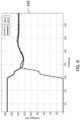
- Fig. 6 illustrates a data stream of computed voltages determined based on the method according to an embodiment of the present disclosure.
- Plot 610 illustrates U opA and U restrainA computed using the data streams illustrated in subplots 510 and 520 and based on the method shown in the flow chart of Fig. 4 .
- the phase-A-to-ground fault may be determined based on the criterion of eq. (15).
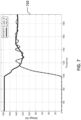
- U opA and U restrainA computed based on the method shown in Fig. 1 is shown in Fig. 7 .
- Plot 710 illustrates U opA and U restrainA computed using the data streams illustrated in subplots 510 and 520.
- U opA and U restrainA computed based on the method according to an embodiment of the present disclosure fluctuates comparatively less than those computed based on a conventional method, i.e., the results shown in Fig. 7 .
- the maximum error is 3% and 16% for the results obtained based on the method according to an embodiment of the present disclosure and on the conventional method, respectively.
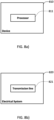
- the device 810 may be a device for controlling an electrical system comprising a transmission line, the device comprising a processor 811 being configured to: obtain measurements of a first at least one electrical parameter being measured at a first location on the transmission line of the electrical system; determine, in a time-domain, a second at least one electrical parameter for a second location on the transmission line of the electrical system based on the measurements of the first at least one electrical parameter; determine, in a frequency-domain, a third at least one electrical parameter for the second location on the transmission line of the electrical system based on the second at least one electrical parameter; and control or protecting the transmission line of (within) the electrical system based on the third at least one electrical parameter.
- the processor 811 is configured to perform the method according to any one of the embodiments disclosed herein.
- Fig. 8b illustrates an electrical system implemented according to an embodiment of the present disclosure.
- the electrical system 820 comprises a transmission line 821.
- the electrical system 820 may be controlled by the method according to any one of the embodiments disclosed herein.
- Fig. 8c illustrates a system implemented according to an embodiment of the present disclosure.
- the system 800 may be a system 800 for controlling an electrical system 820 comprising a transmission line 821, the system 800 comprising the electrical system 820 and the device 810 according to any one of the embodiments disclosed herein.
- first and second elements do not mean that only two elements can be employed, or that the first element must precede the second element in some manner.
- any of the various illustrative logical blocks, units, processors, means, circuits, methods and functions described in connection with the aspects disclosed herein can be implemented by electronic hardware (e.g., a digital implementation, an analogue implementation, or a combination of the two), firmware, various forms of program or design code incorporating instructions (which can be referred to herein, for convenience, as "software” or a "software unit”), or any combination of these techniques.
- a processor, device, component, circuit, structure, machine, unit, etc. can be configured to perform one or more of the functions described herein.
- IC integrated circuit
- DSP digital signal processor
- ASIC application specific integrated circuit
- FPGA field programmable gate array
- the logical blocks, units, and circuits can further include antennas and/or transceivers to communicate with various components within the network or within the device.
- a general purpose processor can be a microprocessor, but in the alternative, the processor can be any conventional processor, controller, or state machine.
- a processor can also be implemented as a combination of computing devices, e.g., a combination of a DSP and a microprocessor, a plurality of microprocessors, one or more microprocessors in conjunction with a DSP core, or any other suitable configuration to perform the functions described herein. If implemented in software, the functions can be stored as one or more instructions or code on a computer-readable medium. Thus, the steps of a method or algorithm disclosed herein can be implemented as software stored on a computer-readable medium.
- Computer-readable media includes both computer storage media and communication media including any medium that can be enabled to transfer a computer program or code from one place to another.
- a storage media can be any available media that can be accessed by a computer.
- such computer-readable media can include RAM, ROM, EEPROM, CD-ROM or other optical disk storage, magnetic disk storage or other magnetic storage devices, or any other medium that can be used to store desired program code in the form of instructions or data structures and that can be accessed by a computer.
- memory or other storage may be employed in embodiments of the present disclosure.
- memory or other storage may be employed in embodiments of the present disclosure.
- any suitable distribution of functionality between different functional units, processing logic elements or domains may be used without detracting from the present disclosure.
- functionality illustrated to be performed by separate processing logic elements, or controllers may be performed by the same processing logic element, or controller.
- references to specific functional units are only references to a suitable means for providing the described functionality, rather than indicative of a strict logical or physical structure or organization.
Landscapes
- Physics & Mathematics (AREA)
- General Physics & Mathematics (AREA)
- Engineering & Computer Science (AREA)
- Power Engineering (AREA)
- Mathematical Physics (AREA)
- Theoretical Computer Science (AREA)
- Remote Monitoring And Control Of Power-Distribution Networks (AREA)
Abstract
The present disclosure relates to a method for controlling or protecting the transmission line within an electrical system comprising a transmission line, the method comprising: obtaining measurements of a first at least one electrical parameter being measured at a first location on the transmission line of the electrical system; determining, in a time-domain, a second at least one electrical parameter for a second location on the transmission line of the electrical system based on the measurements of the first at least one electrical parameter; determining, in a frequency-domain, a third at least one electrical parameter for the second location on the transmission line of the electrical system based on the second at least one electrical parameter; and controlling or protecting the transmission line within the electrical system based on the third at least one electrical parameter.
Description
- The present disclosure relates to a method, a device, and a system for controlling and protecting an electrical system comprising a transmission line.
- In an electrical system comprising a transmission line, it is of high importance to accurately identify a fault type for further corrective actions. Among others, a distance protection is widely used to protect the transmission line. However, due to the increasing use of variable renewable sources, it has become challenging for conventional methods to process the measurements due to distorted fault current waveforms and higher harmonic components, especially for Doubly fed induction generators (DFIG) connected transmission lines. The following briefly discusses the basic principle of the distance protection and the conventional methods being utilized therewith.
- Conventionally, the distance protection relies on computing the measured line impedance, which reflects the positive-sequence impedance of protected transmission lines. The calculation is based on Ohm's law as given below:
There may be two types of calculation loops for impedance measurements: 1) based on phase-to-ground loop and 2) based on phase-phase loop measurement. Phase-to-ground loop impedance may be computed as follows:
- VPG denotes a phase-to-ground voltage measured at a relay location of a transmission line,
- IPG denotes a phase-to-ground loop current measured at a relay location of a transmission line such as IA, IB, IC,
- I 0 denotes a measured zero-sequence current from the three phase currents, i.e.,


- K 0 denotes a compensation factor, e.g.,
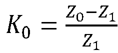
- Z 0 denotes a zero-sequence impedance as seen from the location of the relay to the end of the protected zone, and
- Z 1 denotes a positive-sequence impedance as seen from the location of the relay to the end of the protected zone.
- Phase-to-phase loop impedance may be computed as follows.

- Wherein V Phase,1 and V Phase,2 denote phase-to-ground voltages measured at the relay location of the transmission line, e.g., VA and VB, VB and VC, and VC and VA , and wherein I phase,1 and I Phase,2 denote phase-to-ground voltages measured at the relay location of the transmission line, e.g., IA and IB, IB and IC,and IC and IA.
- As evident from the equations above, the calculations are based on Ohm's law, which requires that both the input variables such as voltages and currents must be in the same frequency domain. For 50 Hz power systems, those measurement inputs should be 50 Hz phasors, so as to justify the calculations above.
- However, in case of variable renewable source connected lines, the measured voltages and currents in the variable renewable source side might not have the same frequencies during fault period, so that equations (1) and (2) might have errors in the calculation results. This may lead to misjudgements such as over-reach or under-reach for a distance protection.
- In view of the above, a first method may utilize sequence voltages with the phase domain calculation to the distance protection reach point. The basic concept of this method is to calculate reach point sequence voltages: positive-sequence voltage at the reach point V a1 ,rp, a negative-sequence voltage at the reach point V a2, rp, and a zero-sequence voltage at the reach point V a0, rp. Then, an operation quantity of eq. (3) and a restrain quantity of eq. (4) can be computed and compared with each other for AG fault in the reach point as an example.


- If the operation quantity, Vop is larger than restrain quantity, Vrestraint, an internal fault within the protection zone can be determined, so that a trip signal can be issued. It is noted that equations (3) and (4) are computed for phase-A related unsymmetrical fault detection such as AG fault, ABG fault, ACG fault, AB fault, and AC fault. In case of phase-B related faults or phase-C related faults, the calculations of equations (3) and (4) may be based on the respective phase signals. For example, for a BG fault, the operation value may be formed by summation of V b0,rp and V b2, rp, while the restrain quantity can be formed by using V b1, rp. Here, the subscript b denotes the phase-B.
- The reach point sequence voltages such as V a1 ,rp, V a2, rp, and V a0,rp can be calculated from the relay measurement point by subtracting the corresponding sequence voltage drops along the line.



- Here, Z 1 ,set, Z 2 ,set, and Z 3,set denote a positive-sequence impedance, a negative-sequence impedance and a zero-sequence impedance from relay location to the reach point, respectively. It is also possible to calculate the reach point voltages by using original three phase transmission line self-impedances and coupling impedances with original three phase currents in phase domain as follows.

- Here, ZSa, ZSb, and ZSc denote a transmission line self-impedance for phase a, phase b and phase c within three phase transmission lines, respectively, and Zab,Zac , and Zbc denote the coupling impedance between two phases such as AB, BC, and AC.
- If the three phase lines are transposed with the same coupling impedance between each two phases and same self-impedance, then we have Zab = Zac = Zbc = Zmm, and ZSa = ZSb = ZSc = ZS. IA, IB, and IC are three phase currents in phasor domain. Ua,RP, Ub,RP, and Uc,RP are phasor domain voltages calculated to the reach point based on setting value as "Reachsetting", which is normally equal to 0.8 as 80% of the line length for a typical setting for line protection. The reach point voltage calculation can also be done with other methods such as distributed transmission line modelling either based on telegraph equations or based on hyperbolic trigonometric functions for receiving end and sending end voltage calculations for long lines. Alternatively, a method may utilize a Pi-model based on lump line parameters for short length of lines.
- The sequence voltage at the reach point (normally it is 80% of line distance protection setting known as Zone 1 can then be calculated as follows.

- Here, in the complex plane, a =-0.5+j0.866, a 2 =-0.5-j0.866 in equation (9), wherein j designates the imaginary part.
- Equations (5), (6), and (7) have used the sequence current to multiply the corresponding sequence impedance, i.e., Ohm's law has been used in the calculation. It is also noted that the calculation method based on equation (8) is also based on Ohm's law. The conventional computational method as described above is summarized in
Fig. 1 . -
Fig. 1 illustrates a flow chart of a conventional computational method. Themethod 100 computes sequence values at a relay point U 1 , U 2 , U 0 , I 1 , I 2 , I 0 by firstly converting sampling values at the relay point ia, ib, ic, ua, ub, uc into frequency domain, and subsequently computing sequence values (S101). Then, the sequence values at a reach point U 1 ', U 2', U 0' are computed based on Ohm's law using the sequence values at a relay point U 1 , U 2 , U 0 , I 1 , I 2 , I 0 (S102). Accordingly, the fault is detected (S103) and corresponding protection action may be issued. - However, the conventional method introduces errors particularly due to signal distortions caused in an electrical system comprising a transmission line, wherein the transmission line is electrically coupled to a, e.g. variable, renewable source. The variable renewable resources may be converters-controlled power plants, in particular including a non-linear controller.
- Thus, there is a need for an improve method, device, and system for controlling an electrical system comprising a transmission line.
- The present disclosure relates to a method for controlling and protecting an electrical system comprising a transmission line, the method comprising: obtaining measurements of a first at least one electrical parameter being measured at a first location on the transmission line of the electrical system; determining, in a time-domain , a second at least one electrical parameter for a second location on the transmission line of the electrical system based on the measurements of the first at least one electrical parameter; determining, in a frequency-domain, a third at least one electrical parameter for the second location on the transmission line of the electrical system based on the second at least one electrical parameter; and controlling or protecting the transmission line of (within) the electrical system based on the third at least one electrical parameter. In this way, the calculation errors introduced due to wave distortion such as frequency shifting, harmonics as well as decaying DC components are minimized comparing with Ohm's law-based calculation solution.
- Various embodiments may preferably implement the following features:
Preferably, determining the second at least one electrical parameter comprises solving at least one time-domain differential equation; and/or determining the third at least one electrical parameter comprises transforming the second at least one electrical parameter in the time-domain to the frequency-domain. - Preferably, determining an internal fault occurrence based on the third at least one electrical parameter and at least one pre-set condition; and controlling or protecting the transmission line of (within) the electrical system further based on the determined internal fault occurrence.
- Preferably, the transmission line comprises a plurality of phases being carried along the transmission line, in particular three phases.
- Preferably, the first at least one electrical parameter is a current and/or voltage of the respective plurality of phases; the second at least one electrical parameter is a voltage, in particular at a reach point, of the respective plurality of phases; and/or the third at least one electrical parameter is a sequence voltage, in particular at the reach point, of the respective plurality of sequence voltages.
- Preferably, the method further comprises: determining at least one phase of the plurality of phases involved in a fault based on the third at least one electrical parameter; and controlling the electrical system further based on the determined at least one phase involved in the fault.
- Preferably, the fault is any one of a phase-to-ground fault, a phase-to-phase fault, and a phase-to-phase-to-ground fault.
- Preferably, the electrical system comprises a transmission line protection system within the electrical system, wherein the transmission line protection system preferably comprises a relay, in particulara distance relay; and controlling, in particular tripping, the transmission line protection system based on a control signal generated according to the third at least one electrical parameter.
- Preferably, the second location is different from the first location.
- Preferably, the transmission line is terminated by a first terminal at a first end of the transmission line, and the transmission line is terminated by a second terminal at a second end of the transmission line, wherein the first end is different from the second end.
- Preferably, the electrical system further comprises a first source being electrically coupled to the first end of the transmission line and a second source being electrically coupled to the second end of the transmission line.
- Preferably, at least one of the first source and the second source is a renewable resource, in particular a variable renewable resource.
- Preferably, at least a portion of the transmission line between the first terminal and the second terminal is protected, in particular using a further protection system, more particularly a distance protection system.
- Preferably, controlling or protecting the transmission line of (within) the electrical system is or comprises tripping a circuit breaker. The circuit breaker may isolate a first portion of the transmission line upon which a fault occurs from a second portion of the transmission line, wherein the first potion of the transmission line is different from the second portion of the transmission line.
- The present disclosure also relates to a device for controlling an electrical system comprising a transmission line, the device comprising a processor being configured to: obtain measurements of a first at least one electrical parameter being measured at a first location on the transmission line of the electrical system; determine, in a time-domain, a second at least one electrical parameter for a second location on the transmission line of the electrical system based on the measurements of the first at least one electrical parameter; determine, in a frequency-domain, a third at least one electrical parameter for the second location on the transmission line of the electrical system based on the second at least one electrical parameter; and control or protecting the transmission line of (within) the electrical system based on the third at least one electrical parameter.
- Preferably, the processor is configured to perform the method according to any one of the preferred embodiments disclosed herein.
- The present disclosure also relates to a system for controlling an electrical system comprising a transmission line, the system comprising the electrical system and the device according to any one of the preferred embodiments disclosed herein.
- Various exemplary embodiments of the present disclosure disclosed herein are directed to providing features that will become readily apparent by reference to the following description when taken in conjunction with the accompanying drawings. In accordance with various embodiments, exemplary systems, methods, and devices are disclosed herein. It is understood, however, that these embodiments are presented by way of example and not limitation, and it will be apparent to those of ordinary skill in the art who read the present disclosure that various modifications to the disclosed embodiments can be made while remaining within the scope of the present disclosure.
- Thus, the present disclosure is not limited to the exemplary embodiments and applications described and illustrated herein. Additionally, the specific order and/or hierarchy of steps in the methods disclosed herein are merely exemplary approaches. Based upon design preferences, the specific order or hierarchy of steps of the disclosed methods or processes can be re-arranged while remaining within the scope of the present disclosure. Thus, those of ordinary skill in the art will understand that the methods and techniques disclosed herein present various steps or acts in a sample order, and the present disclosure is not limited to the specific order or hierarchy presented unless expressly stated otherwise.
- The above and other aspects and their implementations are described in greater detail in the drawings, the descriptions, and the claims.
-
-
Fig. 1 illustrates a flow chart of a conventional computational method. -
Fig. 2 illustrates a flow chart of a method for controlling or protecting the transmission line of an electrical system comprising a transmission line. -
Fig. 3 illustrates a system comprising the electrical system according to an embodiment of the present disclosure. -
Fig. 4 illustrates a method for controlling or protecting the transmission line of an electrical system comprising a transmission line according to an embodiment of the present disclosure. -
Fig. 5 illustrates simulation results including currents and voltages measured at local relay in one end of transmission line of the electrical system according to an embodiment of the present disclosure. -
Fig. 6 illustrates a data stream of computed voltages determined based on the method according to an embodiment of the present disclosure. -
Fig. 7 illustrates a data stream of computed voltages determined based on a conventional method shown inFig. 1 . -
Fig. 8a ) illustrates a device implemented according to an embodiment of the present disclosure. -
Fig. 8b ) illustrates an electrical system implemented according to an embodiment of the present disclosure. -
Fig. 8c ) illustrates a system implemented according to an embodiment of the present disclosure. - In the following, exemplary embodiments of the disclosure will be described. It is noted that some aspects of any one of the described embodiments may also be found in some other embodiments unless otherwise stated or obvious. However, for increased intelligibility, each aspect will only be described in detail when first mentioned and any repeated description of the same aspect will be omitted.
-
FIG. 2 illustrates a flow chart of a method for controlling an electrical system comprising a transmission line. In an embodiment, the transmission line is terminated by a first terminal at a first end of the transmission line, and the transmission line is terminated by a second terminal at a second end of the transmission line, wherein the first end is different from the second end. In an embodiment, the transmission line carries a plurality of phases, in particular three phases. In an embodiment, the electrical system further comprises a first source being electrically coupled to the first end of the transmission line and a second source being electrically coupled to the second end of the transmission line. In an embodiment, at least one of the first source and the second source is a renewable resource. In an embodiment, at least a portion of the transmission line between the first terminal and the second terminal is protected, in particular using a further protection system, more particularly a distance protection system. - At S201, measurements of a first at least one electrical parameter being measured at a first location on the transmission line of the electrical system are obtained. It is understood by the skilled person that the term "obtain" may refer to the action of receiving. That is, the measurements may be received. For instance, the measurements may be received from a device comprising at least one measurement unit, wherein the at least one measurement unit is configured to measure the first at least one electrical parameter. In an embodiment the device comprises a communication unit, wherein the communication unit is configured to communicate information, in particular transmit information such as the measurements and/or receive information such as a fault location, a trip signal, or the like. In an embodiment, the device comprises a protection element, in particular a tripping element such as a relay. In an embodiment, the device comprises a processor being configured to perform the method shown in
Fig. 2 . In an embodiment, the at least one measurement unit measures the at least one electrical parameter at the first location on the transmission line or at the second location on the transmission line. - At 5202, a second at least one electrical parameter for a second location on the transmission line of the electrical system is determined, in a time-domain, based on the measurements of the first at least one electrical parameter. It is understood by the skilled person that the term "determine" may bear the same meaning as, thus can be interchangeably used with, other terms such as "calculate", "compute", or the like. In an embodiment, determining the second at least one electrical parameter comprises solving at least one time-domain equation, in particular at least one time-domain differential equation. In an embodiment, the determined second at least one electrical parameter is in the time-domain. In an embodiment, the second at least one electrical parameter is a voltage, in particular a reach point voltage, of the respective plurality of phases. Alternatively, or in addition, the second at least one electrical parameter is a current of the respective plurality of phases. The reach point may be the point along the transmission line impedance locus that is intersected by the boundary characteristic, in particular of a protection element, more particularly a tripping element such as a relay. In an embodiment, the second location is different from the first location.
- At S203, a third at least one electrical parameter for the second location on the transmission line of the electrical system is determined, in a frequency-domain, based on the second at least one electrical parameter. In an embodiment, determining the third at least one electrical parameter comprises transforming the second at least one electrical parameter in the time-domain to the frequency-domain. In an embodiment, the third at least one electrical parameter is a sequence voltage, in particular at reach point, of the respective plurality of sequence voltages.
- At 5204, the transmission line of (within) the electrical system is controlled or protected based on the third at least one electrical parameter.
- In an embodiment, determining the second at least one electrical parameter comprises solving at least one time-domain differential equation; and/or determining the third at least one electrical parameter comprises transforming the second at least one electrical parameter in the time-domain to the frequency-domain.
- In an embodiment, the method further comprises determining an internal fault occurrence based on the third at least one electrical parameter and at least one pre-set condition; and controlling or protecting the transmission line of (within) the electrical system further based on the determined internal fault occurrence.
- In an embodiment, the method further comprises determining a fault location based on the third at least one electrical parameter and at least one pre-set condition; and controlling or protecting the transmission line of (within) the electrical system further based on the determined fault location.
- In an embodiment, the transmission line comprises a plurality of phases being carried along the transmission line, in particular three phases.
- In an embodiment, the first at least one electrical parameter is a current and/or voltage of the respective plurality of phases; the second at least one electrical parameter is a voltage, in particular at a reach point, of the respective plurality of phases; and/or the third at least one electrical parameter is a sequence voltage, in particular at the reach point, of the respective plurality of sequence voltages.
- In an embodiment, the method further comprises determining at least one phase of the plurality of phases involved in a fault based on the third at least one electrical parameter; and controlling or protecting the transmission line of (within) the electrical system further based on the determined at least one phase involved in the fault.
- In an embodiment, the fault is any one of a phase-to-ground fault, a phase-to-phase fault, and a phase-to-phase-to-ground fault.
- In an embodiment, the electrical system comprises a transmission line protection system within the electrical system, wherein the transmission line protection system preferably comprises a relay, in particular a distance relay; and controlling, in particular tripping, the transmission line protection system based on a control signal generated according to the third at least one electrical parameter.
- In an embodiment, the second location is different from the first location.
- In an embodiment, the method shown in
Fig. 2 is for controlling a distance protection, wherein the distance protection protects the transmission line comprised in the electrical system. -
Fig. 3 illustrates a system comprising the electrical system according to an embodiment of the present disclosure. Thesystem 300 comprises atransmission line 330. Thetransmission line 330 is terminated by afirst terminal 340 at a first end of the transmission line and thetransmission line 330 is terminated by asecond terminal 350 at a second end of the transmission line, wherein the first end is different from the second end. The transmission line carries three different phases, i.e., phase-A, phase-B, and phase-C. The electrical system further comprises afirst source 310 being electrically coupled to the first end of the transmission line and asecond source 320 being electrically coupled to the second end of the transmission line. Thesystem 300 further comprises arelay 360 being communicatively coupled to a voltage sensor and to a current sensor for measuring the voltages and currents, respectively, of the three phases carried on the transmission line. In an embodiment, therelay 360 comprises the voltage sensor and the current sensor. In an embodiment, a device, in particular an intelligent electronic device, is or comprises therelay 360. In an embodiment, the device comprises a processor being configured to perform the method according to any one of the embodiments disclosed herein. The voltages and currents of the three phases carried on the transmission line are measured at a line end of thesecond terminal 350. For example, in case the line length is 100 km, the measurement points (first andsecond terminal 350 and 340) may be closely located at the two respective ends of the line. The distance between the end of the line and the respective measurement points may be a couple of meters depending on the current transformer locations. The measurements are performed before, during, and/or after a fault occurs. Afault location 310 on the transmission line is indicated by the letter "F" onFig. 3 . -
Fig. 4 illustrates a method for controlling an electrical system comprising a transmission line according to an embodiment of the present disclosure. The method shown inFig. 4 may be a specific embodiment of the method shown inFig. 2 . For illustrative purposes, themethod 400 is described herein in reference to the system illustrated inFig. 3 , but the application of themethod 400 is not limited thereto. - The
method 400 obtains sampling values at a relay point, i.e., a measurement point on thetransmission line 330. The sampling values may be the three phase currents ia, ib, and ic and the three phase voltages ua, ub, and uc being carried on thetransmission line 330. The sampling values may comprise the measurements measured before, during and/or after a fault occurs. The sampling values may be the measurements of a first at least one electrical parameter in S201. - At S401, sampling values at a reach point


- u a,RP (t) denotes a reach point phase-A voltage in time domain,
- u b,RP (t) denotes a reach point phase-B voltage in time domain,
- uc,RP (t) denotes a reach point phase-C voltage in time domain,

- i 0 denotes a zero-sequence current,
- R 0 denotes a zero-sequence resistance to the reach point and
- X 0 denotes a zero-sequence reactance to the reach point.
- In an embodiment, ua,RP (t),ub,RP (t), and uc,RP (t) correspond to the sampling values at reach point

- At S402, sequence values at the reach point


- Ua,RP denotes the reach point phase-A voltage in phasor domain,
- Ub,RP denotes the reach point phase-B voltage in phasor domain,
- Uc,RP denotes the reach point phase-C voltage in phasor domain,
- T denotes a one fundamental power frequency cycle time, e.g., T=20ms for a 50 Hz AC system,
- t 0 denotes a time instant to start Fourier transformation, and
- ω denotes an angular velocity, e.g., ω = 2πf ≈ 314 for a 50 Hz AC system.
- Subsequently the sequence values at the reach point may be obtained as follows.

- At S403, the fault is identified (detected) based on the sequence values at the reach point

transmission line 330, that is involved in the fault. For instance, the following criteria may be used to determine the phase involved in the fault.


- The fault may be an unsymmetrical fault, i.e., any one of a phase-to-ground fault, a phase-to-phase fault, and a phase-to-phase-to-ground fault. The fault may be an internal fault. The internal fault may be a fault occurring within a protection zone reaching point. For example, Zone 1 setting is usually set to 80% of line length. In this case, all faults within 80% of line length from relay measurement point until reaching point will be considered as internal faults. The fault may be an external fault. All faults beyond the reach point of the line may be considered as external faults. and it is required not act to trip. The determined fault types may be further processed. For instance, the method may further comprise generating a control signal, in particular a trip signal, based on the determined fault type. The transmission line of (within) electrical system shown in
Fig. 3 may be controlled or protected based on the control signal, e.g., therelay 360 may or may not trip based on the control signal. In particular, therelay 360 or a circuit breaker (omitted inFig. 3 ) may be tripped based on the control signal, wherein the control signal is generated upon determining an internal fault. - Hereinafter, the following configuration of the
system 300 shown inFig. 3 is considered, unless otherwise stated: the transmission line carries three phases, i.e., phases A, B, and C, thefirst source 310 is an AC grid, thesecond source 320 is a type-3 wind farm generator, and 80% of the line length of the transmission line is set as the reach point. -
Fig. 5 illustrates simulation results of the electrical system according to an embodiment of the present disclosure.Subplot 510 illustrates a data stream of three phase currents ia, ib, and ic which are measured at thetransmission line 330 end of thesecond terminal 350.Subplot 520 illustrates a data stream of three phase voltages ua, ub, and uc which are measured at thetransmission line 330 end of thesecond terminal 350. The fault occurs at time t =100 ms with fault location at Zone 1 boundary (80% of line length from measurement point). The simulated fault is a phase-to-ground fault, in particular phase-A to ground fault. The data streams illustrated insubplots -
Fig. 6 illustrates a data stream of computed voltages determined based on the method according to an embodiment of the present disclosure.Plot 610 illustrates UopA and UrestrainA computed using the data streams illustrated insubplots Fig. 4 . The phase-A-to-ground fault may be determined based on the criterion of eq. (15). For illustrative purposes, UopA and UrestrainA computed based on the method shown inFig. 1 is shown inFig. 7 .Plot 710 illustrates UopA and UrestrainA computed using the data streams illustrated insubplots - As evident from
Fig. 6 andFig. 7 , UopA and UrestrainA computed based on the method according to an embodiment of the present disclosure, i.e., the results shown inFig. 6 , fluctuates comparatively less than those computed based on a conventional method, i.e., the results shown inFig. 7 . Considering UrestrainA as a reference, the maximum error is 3% and 16% for the results obtained based on the method according to an embodiment of the present disclosure and on the conventional method, respectively. -
Fig. 8a ) illustrates a device implemented according to an embodiment of the present disclosure. Thedevice 810 may be a device for controlling an electrical system comprising a transmission line, the device comprising aprocessor 811 being configured to: obtain measurements of a first at least one electrical parameter being measured at a first location on the transmission line of the electrical system; determine, in a time-domain, a second at least one electrical parameter for a second location on the transmission line of the electrical system based on the measurements of the first at least one electrical parameter; determine, in a frequency-domain, a third at least one electrical parameter for the second location on the transmission line of the electrical system based on the second at least one electrical parameter; and control or protecting the transmission line of (within) the electrical system based on the third at least one electrical parameter. - In an embodiment, the
processor 811 is configured to perform the method according to any one of the embodiments disclosed herein. -
Fig. 8b ) illustrates an electrical system implemented according to an embodiment of the present disclosure. Theelectrical system 820 comprises atransmission line 821. Theelectrical system 820 may be controlled by the method according to any one of the embodiments disclosed herein. -
Fig. 8c ) illustrates a system implemented according to an embodiment of the present disclosure. Thesystem 800 may be asystem 800 for controlling anelectrical system 820 comprising atransmission line 821, thesystem 800 comprising theelectrical system 820 and thedevice 810 according to any one of the embodiments disclosed herein. - While various embodiments of the present disclosure have been described above, it should be understood that they have been presented by way of example only, and not by way of limitation. Likewise, the various diagrams may depict an example architectural or configuration, which are provided to enable persons of ordinary skill in the art to understand exemplary features and functions of the present disclosure. Such persons would understand, however, that the present disclosure is not restricted to the illustrated example architectures or configurations, but can be implemented using a variety of alternative architectures and configurations. Additionally, as would be understood by persons of ordinary skill in the art, one or more features of one embodiment can be combined with one or more features of another embodiment described herein. Thus, the breadth and scope of the present disclosure should not be limited by any of the above-described exemplary embodiments.
- It is also understood that any reference to an element herein using a designation such as "first," "second," and so forth does not generally limit the quantity or order of those elements.
- Rather, these designations can be used herein as a convenient means of distinguishing between two or more elements or instances of an element. Thus, a reference to first and second elements does not mean that only two elements can be employed, or that the first element must precede the second element in some manner.
- Additionally, a person having ordinary skill in the art would understand that information and signals can be represented using any of a variety of different technologies and techniques. For example, data, instructions, commands, information, signals, bits and symbols, for example, which may be referenced in the above description can be represented by voltages, currents, electromagnetic waves, magnetic fields or particles, optical fields or particles, or any combination thereof.
- A skilled person would further appreciate that any of the various illustrative logical blocks, units, processors, means, circuits, methods and functions described in connection with the aspects disclosed herein can be implemented by electronic hardware (e.g., a digital implementation, an analogue implementation, or a combination of the two), firmware, various forms of program or design code incorporating instructions (which can be referred to herein, for convenience, as "software" or a "software unit"), or any combination of these techniques.
- To clearly illustrate this interchangeability of hardware, firmware and software, various illustrative components, blocks, units, circuits, and steps have been described above generally in terms of their functionality. Whether such functionality is implemented as hardware, firmware or software, or a combination of these techniques, depends upon the particular application and design constraints imposed on the overall system. Skilled artisans can implement the described functionality in various ways for each particular application, but such implementation decisions do not cause a departure from the scope of the present disclosure. In accordance with various embodiments, a processor, device, component, circuit, structure, machine, unit, etc. can be configured to perform one or more of the functions described herein. The term "configured to" or "configured for" as used herein with respect to a specified operation or function refers to a processor, device, component, circuit, structure, machine, unit, etc. that is physically constructed, programmed and/or arranged to perform the specified operation or function.
- Furthermore, a skilled person would understand that various illustrative methods, logical blocks, units, devices, components and circuits described herein can be implemented within or performed by an integrated circuit (IC) that can include a general purpose processor, a digital signal processor (DSP), an application specific integrated circuit (ASIC), a field programmable gate array (FPGA) or other programmable logic device, or any combination thereof. The logical blocks, units, and circuits can further include antennas and/or transceivers to communicate with various components within the network or within the device. A general purpose processor can be a microprocessor, but in the alternative, the processor can be any conventional processor, controller, or state machine. A processor can also be implemented as a combination of computing devices, e.g., a combination of a DSP and a microprocessor, a plurality of microprocessors, one or more microprocessors in conjunction with a DSP core, or any other suitable configuration to perform the functions described herein. If implemented in software, the functions can be stored as one or more instructions or code on a computer-readable medium. Thus, the steps of a method or algorithm disclosed herein can be implemented as software stored on a computer-readable medium.
- Computer-readable media includes both computer storage media and communication media including any medium that can be enabled to transfer a computer program or code from one place to another. A storage media can be any available media that can be accessed by a computer. By way of example, and not limitation, such computer-readable media can include RAM, ROM, EEPROM, CD-ROM or other optical disk storage, magnetic disk storage or other magnetic storage devices, or any other medium that can be used to store desired program code in the form of instructions or data structures and that can be accessed by a computer.
- Additionally, memory or other storage, as well as communication components, may be employed in embodiments of the present disclosure. It will be appreciated that, for clarity purposes, the above description has described embodiments of the present disclosure with reference to different functional units and processors. However, it will be apparent that any suitable distribution of functionality between different functional units, processing logic elements or domains may be used without detracting from the present disclosure. For example, functionality illustrated to be performed by separate processing logic elements, or controllers, may be performed by the same processing logic element, or controller. Hence, references to specific functional units are only references to a suitable means for providing the described functionality, rather than indicative of a strict logical or physical structure or organization.
- Various modifications to the implementations described in this disclosure will be readily apparent to those skilled in the art, and the general principles defined herein can be applied to other implementations without departing from the scope of this disclosure. Thus, the disclosure is not intended to be limited to the implementations shown herein, but is to be accorded the widest scope consistent with the novel features and principles disclosed herein, as recited in the claims below.
Claims (14)
- A method for controlling an electrical system comprising a transmission line, the method comprising:obtaining measurements of a first at least one electrical parameter being measured at a first location on the transmission line of the electrical system;determining, in a time-domain, a second at least one electrical parameter for a second location on the transmission line of the electrical system based on the measurements of the first at least one electrical parameter;determining, in a frequency-domain, a third at least one electrical parameter for the second location on the transmission line of the electrical system based on the second at least one electrical parameter; andcontrolling or protecting the transmission line of the electrical system based on the third at least one electrical parameter.
- The method of claim 1, whereindetermining the second at least one electrical parameter comprises solving at least one time-domain differential equation; and/ordetermining the third at least one electrical parameter comprises transforming the second at least one electrical parameter in the time-domain to the frequency-domain.
- The method of claim 1 or 2, further comprising:determining an internal fault occurrence based on the third at least one electrical parameter and at least one pre-set condition; andcontrolling or protecting the transmission line within the electrical system further based on the determined internal fault occurrence.
- The method of any one of claims 1 to 3, further comprising:determining a fault location based on the third at least one electrical parameter and at least one pre-set condition; andcontrolling the electrical system further based on the determined fault location.
- The method of any one of claims 1 to 4, wherein the transmission line comprises a plurality of phases being carried along the transmission line, in particularthree phases.
- The method of claim 5, whereinthe first at least one electrical parameter is a current and/or voltage of the respective plurality of phases;the second at least one electrical parameter is a voltage, in particular at a reach point, of the respective plurality of phases; and/orthe third at least one electrical parameter is a sequence voltage, in particular at the reach point, of the respective plurality of sequence voltages.
- The method of claim 5 or 6, further comprising:determining at least one phase of the plurality of phases involved in a fault based on the third at least one electrical parameter; andcontrolling or protecting the transmission line of the electrical system further based on the determined at least one phase involved in the fault.
- The method of any one of claims 5 to 7, wherein the fault is any one of a phase-to-ground fault, a phase-to-phase fault, and a phase-to-phase-to-ground fault.
- The method of any one of claims 1 to 8, whereinthe electrical system comprises a transmission line protection system within the electrical system, wherein the transmission line protection system preferably comprises a relay, in particular a distance relay; andcontrolling or protecting the transmission line of the electrical system comprises controlling, in particular tripping, the transmission line protection system based on a control signal generated according to the third at least one electrical parameter.
- The method of any one of claims 1 to 9, wherein the second location is different from the first location.
- The method of any one of claims 1 to 10, wherein controlling or protecting the transmission line of the electrical system based on the third at least one electrical parameter comprises protecting the electrical system based on the third at least one electrical parameter, preferably including issuing a trip comment to a corresponding circuit breaker and thereby isolating a respective fault.
- A device for controlling or protecting the transmission line of an electrical system comprising a transmission line, the device comprising a processor being configured to:obtain measurements of a first at least one electrical parameter being measured at a first location on the transmission line of the electrical system;determine, in a time-domain, a second at least one electrical parameter for a second location on the transmission line of the electrical system based on the measurements of the first at least one electrical parameter;determine, in a frequency-domain, a third at least one electrical parameter for the second location on the transmission line of the electrical system based on the second at least one electrical parameter; andcontrol or protecting the transmission line of the electrical system based on the third at least one electrical parameter.
- The device of claim 12, wherein the processor is configured to perform the method of any one of claims 2 to 11.
- A system for controlling or protecting the transmission line of an electrical system comprising a transmission line, the system comprising the electrical system and the device of claim 12 or 13.
Priority Applications (3)
| Application Number | Priority Date | Filing Date | Title |
|---|---|---|---|
| EP23209147.0A EP4554026A1 (en) | 2023-11-10 | 2023-11-10 | Line distance protection in an electrical power system based on a reach point voltage calculation |
| CN202480064336.6A CN121986426A (en) | 2023-11-10 | 2024-11-06 | Power system line distance protection based on setting point voltage calculation |
| PCT/EP2024/081324 WO2025099058A1 (en) | 2023-11-10 | 2024-11-06 | Line distance protection in an electrical power system based on a reach point voltage calculation |
Applications Claiming Priority (1)
| Application Number | Priority Date | Filing Date | Title |
|---|---|---|---|
| EP23209147.0A EP4554026A1 (en) | 2023-11-10 | 2023-11-10 | Line distance protection in an electrical power system based on a reach point voltage calculation |
Publications (1)
| Publication Number | Publication Date |
|---|---|
| EP4554026A1 true EP4554026A1 (en) | 2025-05-14 |
Family
ID=88778856
Family Applications (1)
| Application Number | Title | Priority Date | Filing Date |
|---|---|---|---|
| EP23209147.0A Pending EP4554026A1 (en) | 2023-11-10 | 2023-11-10 | Line distance protection in an electrical power system based on a reach point voltage calculation |
Country Status (3)
| Country | Link |
|---|---|
| EP (1) | EP4554026A1 (en) |
| CN (1) | CN121986426A (en) |
| WO (1) | WO2025099058A1 (en) |
Citations (3)
| Publication number | Priority date | Publication date | Assignee | Title |
|---|---|---|---|---|
| CN103296652A (en) * | 2013-05-19 | 2013-09-11 | 国家电网公司 | Zero-sequence voltage protection method for single-phase grounding faults of power transmission line |
| WO2018227466A1 (en) * | 2017-06-15 | 2018-12-20 | Abb Schweiz Ag | Method for detecting fault in power transmission line and protection system using the same |
| CN115061020A (en) * | 2022-06-20 | 2022-09-16 | 广东电网有限责任公司广州供电局 | A method and device for evaluating insulation of three-core cable |
-
2023
- 2023-11-10 EP EP23209147.0A patent/EP4554026A1/en active Pending
-
2024
- 2024-11-06 WO PCT/EP2024/081324 patent/WO2025099058A1/en active Pending
- 2024-11-06 CN CN202480064336.6A patent/CN121986426A/en active Pending
Patent Citations (3)
| Publication number | Priority date | Publication date | Assignee | Title |
|---|---|---|---|---|
| CN103296652A (en) * | 2013-05-19 | 2013-09-11 | 国家电网公司 | Zero-sequence voltage protection method for single-phase grounding faults of power transmission line |
| WO2018227466A1 (en) * | 2017-06-15 | 2018-12-20 | Abb Schweiz Ag | Method for detecting fault in power transmission line and protection system using the same |
| CN115061020A (en) * | 2022-06-20 | 2022-09-16 | 广东电网有限责任公司广州供电局 | A method and device for evaluating insulation of three-core cable |
Non-Patent Citations (1)
| Title |
|---|
| SCHWEITZER EDMUND O ET AL: "Distance protection: Why have we started with a circle, does it matter, and what else is out there?", 2018 71ST ANNUAL CONFERENCE FOR PROTECTIVE RELAY ENGINEERS (CPRE), IEEE, 26 March 2018 (2018-03-26), pages 1 - 19, XP033336067, DOI: 10.1109/CPRE.2018.8349791 * |
Also Published As
| Publication number | Publication date |
|---|---|
| CN121986426A (en) | 2026-05-05 |
| WO2025099058A1 (en) | 2025-05-15 |
Similar Documents
| Publication | Publication Date | Title |
|---|---|---|
| US11522355B2 (en) | Method and apparatus for use in earth-fault protection | |
| US11831146B2 (en) | Method and apparatus for use in earth-fault protection | |
| EP1992954B1 (en) | Method for determining location of phase-to-earth fault | |
| CN103529356B (en) | For the method and apparatus determining the distance from relatively fault | |
| EP3069426B1 (en) | Method and apparatus of reactor turn-to-turn protection | |
| EP2000811B1 (en) | Method for determining location of phase-to-earth fault | |
| EP2113778B1 (en) | System and method for determining location of phase-to-phase fault or three-phase fault | |
| WO1998029752A1 (en) | System for locating faults and estimating fault resistance in distribution networks with tapped loads | |
| WO1995024014A2 (en) | One-terminal data fault location system | |
| WO1998029752A9 (en) | System for locating faults and estimating fault resistance in distribution networks with tapped loads | |
| EP2402774B1 (en) | Method and apparatus for determining distance to phase-to-earth fault | |
| US5764044A (en) | Process for producing time dependent waveforms of positive and negative symmetrical sequence components of a power system's voltages or currents | |
| CN104965151A (en) | Fault distance detecting method based on voltage fault component of fault point | |
| Gilbert et al. | High speed transmission line fault impedance calculation using a dedicated minicomputer | |
| CN1916651B (en) | Method and system for determining location of phase-to-ground fault | |
| Bainy et al. | Enhanced generalized alpha plane for numerical differential protection applications | |
| CN103245874B (en) | For determining the method and apparatus in the direction of fault | |
| EP2378296B1 (en) | Method and arrangement for determining impedance values | |
| EP2070170B1 (en) | Method and apparatus for determining circular characteristic | |
| WO2025099058A1 (en) | Line distance protection in an electrical power system based on a reach point voltage calculation | |
| EP4618342A1 (en) | Phase selection based on reach point voltage calculation for line distance protection | |
| EP4618340A1 (en) | Distance protection for symmetrical three phase faults reach point voltage calculation | |
| EP4618344A1 (en) | Distance protection for fault detection | |
| EP4618343A1 (en) | Distance protection for symmetrical three phase faults | |
| Klapper et al. | Reliability of transmission by means of line impedance and K-Factor measurement |
Legal Events
| Date | Code | Title | Description |
|---|---|---|---|
| PUAI | Public reference made under article 153(3) epc to a published international application that has entered the european phase |
Free format text: ORIGINAL CODE: 0009012 |
|
| STAA | Information on the status of an ep patent application or granted ep patent |
Free format text: STATUS: THE APPLICATION HAS BEEN PUBLISHED |
|
| AK | Designated contracting states |
Kind code of ref document: A1 Designated state(s): AL AT BE BG CH CY CZ DE DK EE ES FI FR GB GR HR HU IE IS IT LI LT LU LV MC ME MK MT NL NO PL PT RO RS SE SI SK SM TR |
|
| STAA | Information on the status of an ep patent application or granted ep patent |
Free format text: STATUS: REQUEST FOR EXAMINATION WAS MADE |
|
| 17P | Request for examination filed |
Effective date: 20251024 |