EP4553978A1 - Secondary battery - Google Patents
Secondary battery Download PDFInfo
- Publication number
- EP4553978A1 EP4553978A1 EP24188136.6A EP24188136A EP4553978A1 EP 4553978 A1 EP4553978 A1 EP 4553978A1 EP 24188136 A EP24188136 A EP 24188136A EP 4553978 A1 EP4553978 A1 EP 4553978A1
- Authority
- EP
- European Patent Office
- Prior art keywords
- case
- spacer
- wall
- secondary battery
- electrode assembly
- Prior art date
- Legal status (The legal status is an assumption and is not a legal conclusion. Google has not performed a legal analysis and makes no representation as to the accuracy of the status listed.)
- Pending
Links
Images





Classifications
-
- H—ELECTRICITY
- H01—ELECTRIC ELEMENTS
- H01M—PROCESSES OR MEANS, e.g. BATTERIES, FOR THE DIRECT CONVERSION OF CHEMICAL ENERGY INTO ELECTRICAL ENERGY
- H01M50/00—Constructional details or processes of manufacture of the non-active parts of electrochemical cells other than fuel cells, e.g. hybrid cells
- H01M50/20—Mountings; Secondary casings or frames; Racks, modules or packs; Suspension devices; Shock absorbers; Transport or carrying devices; Holders
- H01M50/289—Mountings; Secondary casings or frames; Racks, modules or packs; Suspension devices; Shock absorbers; Transport or carrying devices; Holders characterised by spacing elements or positioning means within frames, racks or packs
-
- H—ELECTRICITY
- H01—ELECTRIC ELEMENTS
- H01M—PROCESSES OR MEANS, e.g. BATTERIES, FOR THE DIRECT CONVERSION OF CHEMICAL ENERGY INTO ELECTRICAL ENERGY
- H01M50/00—Constructional details or processes of manufacture of the non-active parts of electrochemical cells other than fuel cells, e.g. hybrid cells
- H01M50/40—Separators; Membranes; Diaphragms; Spacing elements inside cells
- H01M50/471—Spacing elements inside cells other than separators, membranes or diaphragms; Manufacturing processes thereof
- H01M50/474—Spacing elements inside cells other than separators, membranes or diaphragms; Manufacturing processes thereof characterised by their position inside the cells
-
- H—ELECTRICITY
- H01—ELECTRIC ELEMENTS
- H01M—PROCESSES OR MEANS, e.g. BATTERIES, FOR THE DIRECT CONVERSION OF CHEMICAL ENERGY INTO ELECTRICAL ENERGY
- H01M50/00—Constructional details or processes of manufacture of the non-active parts of electrochemical cells other than fuel cells, e.g. hybrid cells
- H01M50/30—Arrangements for facilitating escape of gases
- H01M50/35—Gas exhaust passages comprising elongated, tortuous or labyrinth-shaped exhaust passages
- H01M50/367—Internal gas exhaust passages forming part of the battery cover or case; Double cover vent systems
-
- H—ELECTRICITY
- H01—ELECTRIC ELEMENTS
- H01M—PROCESSES OR MEANS, e.g. BATTERIES, FOR THE DIRECT CONVERSION OF CHEMICAL ENERGY INTO ELECTRICAL ENERGY
- H01M50/00—Constructional details or processes of manufacture of the non-active parts of electrochemical cells other than fuel cells, e.g. hybrid cells
- H01M50/10—Primary casings; Jackets or wrappings
- H01M50/102—Primary casings; Jackets or wrappings characterised by their shape or physical structure
- H01M50/103—Primary casings; Jackets or wrappings characterised by their shape or physical structure prismatic or rectangular
-
- H—ELECTRICITY
- H01—ELECTRIC ELEMENTS
- H01M—PROCESSES OR MEANS, e.g. BATTERIES, FOR THE DIRECT CONVERSION OF CHEMICAL ENERGY INTO ELECTRICAL ENERGY
- H01M50/00—Constructional details or processes of manufacture of the non-active parts of electrochemical cells other than fuel cells, e.g. hybrid cells
- H01M50/10—Primary casings; Jackets or wrappings
- H01M50/147—Lids or covers
- H01M50/148—Lids or covers characterised by their shape
- H01M50/15—Lids or covers characterised by their shape for prismatic or rectangular cells
-
- H—ELECTRICITY
- H01—ELECTRIC ELEMENTS
- H01M—PROCESSES OR MEANS, e.g. BATTERIES, FOR THE DIRECT CONVERSION OF CHEMICAL ENERGY INTO ELECTRICAL ENERGY
- H01M50/00—Constructional details or processes of manufacture of the non-active parts of electrochemical cells other than fuel cells, e.g. hybrid cells
- H01M50/20—Mountings; Secondary casings or frames; Racks, modules or packs; Suspension devices; Shock absorbers; Transport or carrying devices; Holders
- H01M50/289—Mountings; Secondary casings or frames; Racks, modules or packs; Suspension devices; Shock absorbers; Transport or carrying devices; Holders characterised by spacing elements or positioning means within frames, racks or packs
- H01M50/291—Mountings; Secondary casings or frames; Racks, modules or packs; Suspension devices; Shock absorbers; Transport or carrying devices; Holders characterised by spacing elements or positioning means within frames, racks or packs characterised by their shape
-
- H—ELECTRICITY
- H01—ELECTRIC ELEMENTS
- H01M—PROCESSES OR MEANS, e.g. BATTERIES, FOR THE DIRECT CONVERSION OF CHEMICAL ENERGY INTO ELECTRICAL ENERGY
- H01M50/00—Constructional details or processes of manufacture of the non-active parts of electrochemical cells other than fuel cells, e.g. hybrid cells
- H01M50/30—Arrangements for facilitating escape of gases
- H01M50/342—Non-re-sealable arrangements
- H01M50/3425—Non-re-sealable arrangements in the form of rupturable membranes or weakened parts, e.g. pierced with the aid of a sharp member
-
- H—ELECTRICITY
- H01—ELECTRIC ELEMENTS
- H01M—PROCESSES OR MEANS, e.g. BATTERIES, FOR THE DIRECT CONVERSION OF CHEMICAL ENERGY INTO ELECTRICAL ENERGY
- H01M50/00—Constructional details or processes of manufacture of the non-active parts of electrochemical cells other than fuel cells, e.g. hybrid cells
- H01M50/40—Separators; Membranes; Diaphragms; Spacing elements inside cells
- H01M50/471—Spacing elements inside cells other than separators, membranes or diaphragms; Manufacturing processes thereof
- H01M50/477—Spacing elements inside cells other than separators, membranes or diaphragms; Manufacturing processes thereof characterised by their shape
-
- H—ELECTRICITY
- H01—ELECTRIC ELEMENTS
- H01M—PROCESSES OR MEANS, e.g. BATTERIES, FOR THE DIRECT CONVERSION OF CHEMICAL ENERGY INTO ELECTRICAL ENERGY
- H01M50/00—Constructional details or processes of manufacture of the non-active parts of electrochemical cells other than fuel cells, e.g. hybrid cells
- H01M50/20—Mountings; Secondary casings or frames; Racks, modules or packs; Suspension devices; Shock absorbers; Transport or carrying devices; Holders
- H01M50/202—Casings or frames around the primary casing of a single cell or a single battery
-
- Y—GENERAL TAGGING OF NEW TECHNOLOGICAL DEVELOPMENTS; GENERAL TAGGING OF CROSS-SECTIONAL TECHNOLOGIES SPANNING OVER SEVERAL SECTIONS OF THE IPC; TECHNICAL SUBJECTS COVERED BY FORMER USPC CROSS-REFERENCE ART COLLECTIONS [XRACs] AND DIGESTS
- Y02—TECHNOLOGIES OR APPLICATIONS FOR MITIGATION OR ADAPTATION AGAINST CLIMATE CHANGE
- Y02E—REDUCTION OF GREENHOUSE GAS [GHG] EMISSIONS, RELATED TO ENERGY GENERATION, TRANSMISSION OR DISTRIBUTION
- Y02E60/00—Enabling technologies; Technologies with a potential or indirect contribution to GHG emissions mitigation
- Y02E60/10—Energy storage using batteries
Definitions
- aspects of embodiments of the present disclosure relate to a secondary battery.
- Secondary batteries are designed to be chargeable and dischargeable, unlike primary batteries.
- Small-capacity secondary batteries may be used in small, portable electronic devices, such as mobile phones, laptop computers, and camcorders, while high-capacity secondary batteries may be used as power sources for driving motors in hybrid vehicles and electric vehicles.
- a secondary battery includes an electrode assembly that performs a charging/discharging operation, a case accommodating the electrode assembly, a cap plate coupled to an opening in the case, and an electrode terminal that draws the electrode assembly to the outside of the cap plate.
- a vent part is provided in the case, which is designed to burst in response to increased pressure inside the case before another portion of the case bursts, thereby ensuring the safe flow of gas away from the secondary battery.
- the vent part is provided on an upper surface of the case adjacent to the electrode terminal.
- Recent secondary battery designs have placed the vent part at a bottom of the case opposite to the electrode terminal, also referred to as a downward vent structure.
- a spacer is often included at the bottom of the case to fix the jelly-roll electrode assembly, and the spacer can impede the smooth flow of gas from inside the case to outside the case through the vent part when it is arranged in the bottom of the case.
- Embodiments of the present disclosure provide a secondary battery including a spacer that fixes (e.g., fixes a position of) an electrode assembly and has (or provides) a discharge passage for the smooth discharge of a gas when a vent part is disposed at a lower portion of a case opposite to an electrode terminal, also known as a downward vent structure.
- a spacer that fixes (e.g., fixes a position of) an electrode assembly and has (or provides) a discharge passage for the smooth discharge of a gas when a vent part is disposed at a lower portion of a case opposite to an electrode terminal, also known as a downward vent structure.
- a secondary battery includes: an electrode assembly; a case accommodating the electrode assembly; a cap plate coupled to an opening in the case; and a spacer in the case.
- the case has a vent part extending through a surface facing the cap plate, and the spacer is accommodated in the case between a lower portion of the electrode assembly and the vent part.
- the spacer has: a surface portion contacting the electrode assembly and a space portion below the surface portion; an opening in an area of the surface portion corresponding to the vent part; and a gas discharge hole extending around the opening. Gas generated in the case is discharged to the outside through the vent part via the space portion and the gas discharge hole in the spacer.
- the gas discharge hole may extend through the surface portion of the spacer and may be provided in plurality, and the plurality of gas discharge holes may be arranged in longitudinal and transverse directions in the surface portion.
- the spacer may have an outer wall protruding downwardly along a periphery of the surface portion and an inner wall protruding downwardly along a periphery of the opening in the spacer.
- the surface portion may be spaced apart from a lower bottom surface of the case in which the vent part is formed by the outer wall and the inner wall, and the space portion may be surrounded by the surface portion, the outer wall, the inner wall, and the lower bottom surface of the case.
- the outer wall may be continuously arranged along a long side and a short side of the spacer, a plurality of exhaust holes may be in the outer wall and the inner wall on the short side, and the inside of the case may communicate with the space portion of the spacer via the exhaust holes.
- the exhaust holes in the outer wall and the exhaust holes in the inner wall may be in one-to-one correspondence with each other, and the corresponding exhaust holes may be arranged in a straight line.
- the gas discharge holes arranged in the longitudinal direction may be arranged above a straight path that connects the exhaust holes in the outer wall to the exhaust holes in the inner wall.
- the spacer may be spaced a distance from an inner surface of the case in the longitudinal direction.
- the expression "at least one of a, b, or c" indicates only a, only b, only c, both a and b, both a and c, both b and c, all of a, b, and c, or variations thereof.
- the terms “use,” “using,” and “used” may be considered synonymous with the terms “utilize,” “utilizing,” and “utilized,” respectively.
- the terms “substantially,” “about,” and similar terms are used as terms of approximation and not as terms of degree, and are intended to account for the inherent variations in measured or calculated values that would be recognized by those of ordinary skill in the art.
- first, second, third, etc. may be used herein to describe various elements, components, regions, layers, and/or sections, these elements, components, regions, layers, and/or sections should not be limited by these terms. These terms are used to distinguish one element, component, region, layer, or section from another element, component, region, layer, or section. Thus, a first element, component, region, layer, or section discussed below could be termed a second element, component, region, layer, or section without departing from the teachings of example embodiments.
- spatially relative terms such as “beneath,” “below,” “lower,” “above,” “upper,” and the like, may be used herein for ease of description to describe one element or feature's relationship to another element(s) or feature(s) as illustrated in the figures. It will be understood that the spatially relative terms are intended to encompass different orientations of the device in use or operation in addition to the orientation depicted in the figures. For example, if the device in the figures is turned over, elements described as “below” or “beneath” other elements or features would then be oriented “above” or “over” the other elements or features. Thus, the term “below” may encompass both an orientation of above and below. The device may be otherwise oriented (rotated 90 degrees or at other orientations), and the spatially relative descriptors used herein should be interpreted accordingly.
- one of the prismatic/pouch/circular batteries is selected, and the selected battery is described as having a general structure, and for commonly applied technologies, the general structure of prismatic/pouch/round cells is described.
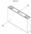
- a vent part 17 may be provided in the case 15 of the secondary battery.
- a vent plate may be coupled to a lower portion of a vent hole defined in the case 15. Because the vent plate is thinner than a portion of the case 15, if an internal pressure of the case 15 increases due to overcharging, the vent plate is broken (or bursts) before other portions of the case 15 to discharge the high-temperature gas and pressure to the outside, thereby ensuring safety of the secondary battery.
- the vent part 17 is disposed on a bottom surface of the case 15 instead of at an upper portion of the case 15 .
- the vent part 17 is disposed at a side of the case 15 opposite to the electrode terminals 21, 22, a vent hole is defined in the bottom surface of the case 15, and a notched vent plate is sealed and coupled to the vent hole. If a high-pressure gas is generated inside the secondary battery, the vent plate disposed at the lower portion of the case 15 is broken (e.g., bursts) to cause a pressure difference inside and outside the case, and thus, the gas moves toward a lower side of the case 15 due to the pressure difference and is then discharged to the outside through the vent hole.
- bursts e.g., bursts
- a spacer 20 may be interposed between a lower end of the electrode assembly 10 and the bottom surface of the case 15.
- the spacer 20 fixes a jelly-roll electrode assembly 10 so that it is not shaken or moved within the case 15.
- the spacer 20 is made of an insulating material to maintain insulation between the electrode assembly 10 and the case 15 and protects the electrode assembly 10 by buffering an external impact.
- the spacer 20 disposed on the bottom surface of the case 15 covers the vent part 17, thereby blocking a gas discharge path toward the vent part 17 and causing restriction in smooth gas discharge. Furthermore, because the spacer 20 does not have a separate gas flow path, it is difficult to smoothly discharge the gas.
- a secondary battery 100 includes an electrode assembly 110, a case 130, and a cap plate 150.
- the electrode assembly 110 may be provided by winding or stacking a stack of a first electrode plate, a separator, and a second electrode plate, each of which is provided in a thin plate or film shape. If the electrode assembly 110 is a rolled stack, a winding axis may be parallel to a longitudinal direction of the case 130. In some embodiments, the electrode assembly 110 may be a stack type rather than a winding type, and the shape of the electrode assembly 110 is not limited to the embodiments. In some embodiments, the electrode assembly 110 may include a Z-stack electrode assembly 110 in which a positive electrode plate and a negative electrode plate are inserted into both sides of the separator, which is bent in the form of a Z-stack.
- the electrode assembly 110 may be stacked so that one or more electrode assemblies 110 are adjacent to each other and are accommodated in the case 130. In some embodiments, the number of electrode assemblies 110 may not be limited thereto.
- the first electrode plate of the electrode assembly 110 may act as a negative electrode, and the second electrode plate may act as a positive electrode. In other embodiments, the first electrode plate may act as a positive electrode, and the second electrode plate may act as a negative electrode.
- the first electrode plate may be formed by applying a first electrode active material, such as graphite or carbon, to a first electrode current collector plate made of a metal foil, such as copper, a copper alloy, nickel, or a nickel alloy.
- the first electrode plate may include a first electrode tab (e.g., a first non-coating portion) that is a portion of the first electrode current collector plate not coated with the first electrode active material.
- the first electrode tab may act as a path for a current flow between the first electrode plate and a first current collector.
- the first electrode tab may be provided by being cut in advance to protrude to one side when the first electrode plate is manufactured and may protrude more to one side than (e.g., may protrude beyond) a separator without separate cutting.
- the second electrode plate may be provided by applying a second electrode active material, such as transition metal oxide, to a second electrode current collector plate made of metal foil, such as aluminium or an aluminium alloy.
- the second electrode plate may include a second electrode tab (e.g., a second non-coating portion) that is a portion of the second electrode current collector not coated with the second electrode active material.
- the second electrode tab may be a passage through which current flow between the second electrode plate and a second current collector.
- the second electrode tab may be provided by being cut in advance to protrude to the other side when the second electrode plate is manufactured and may protrude more to the other side than (e.g., may protrude beyond) the separator without separate cutting.
- the first electrode tab may be disposed on a side surface at a left end of the electrode assembly 110
- the second electrode tab may be disposed on a side surface at a right end of the electrode assembly 110 or may disposed on one surface in the same direction as the first electrode tab.
- FIG. 2 an embodiment in which the left and right sides of the electrode assembly 110 are, for convenience of explanation, based on the secondary battery 100 is illustrated, but the position of the secondary battery 100 may be changed when the secondary battery 100 is rotated left and right or up and down.
- a first electrode tab of the first electrode plate and a second electrode tab of the second electrode plate may be disposed on both ends (e.g., opposite ends) of the electrode assembly 110 as described above, respectively.
- the electrode assembly 110 may be accommodated in the case 130 together with an electrolyte.
- the first current collector and the second current collector may be welded and connected to the first electrode tab of the first electrode plate and the second electrode tab of the second electrode plate, which are exposed at both sides, respectively.
- the case 130 may accommodate the electrode assembly 110.
- the case 130 may have a substantially rectangular parallelepiped shape to provide a space for accommodating the electrode assembly 110 and the electrolyte therein and may have an opening connecting external and internal spaces to each other defined in one surface of the rectangular parallelepiped shape. The opening may allow the electrode assembly 110 to be inserted into the case 130.
- the present disclosure is not limited thereto, and the case 130 may have various, suitable shapes, such as a circular shape or a pouch shape.
- the case 130 may be made of a metal, such as aluminium, aluminium alloy, or nickel-plated steel, or may be a laminated film or plastic that constitutes the pouch or case.
- the cap plate 150 may be installed in the opening of the case 130 to seal the opening in the case 130.
- the case 130 and the cap plate 150 may be made of aluminium and welded to each other.
- the cap plate 150 may further include terminal holes (e.g., terminal openings) H1 and H2 and an electrolyte injection port.
- the electrolyte injection port may allow the electrolyte to be injected into the case 130 after coupling and welding the cap plate 150 to the case 130.
- Negative and positive terminals 21 and 22 may be electrically and mechanically connected to the electrode assembly 110 and installed in the terminal holes H1 and H2 in the cap plate 150. In some embodiments, the negative and positive terminals 21 and 22 may be electrically connected to the negative and positive terminals 21 and 22 of the electrode assembly 110, respectively. In some embodiments, the electrode assembly 110 may be drawn to the outside of the case 130 through the negative and positive terminals 21 and 22.
- a vent part 170 may be defined to pass through a surface of the case 130 opposite to the cap plate 150.
- the cap plate 150 may be coupled to an upper opening in the case 130, and the vent part 170 may be provided in a lower, bottom surface of the case 130 opposite to the cap plate 150 on the case 130.
- a high-temperature gas and pressure, which are generated inside the case 130, may be discharged to the outside of the case 130 through the vent part 170.
- the vent part 170 may have a vent hole (e.g., a vent opening) and a vent plate sealed and coupled around (or to) the vent hole.
- a recess part may be provided in the above-described vent part formation surface of the case 130, for example, in the lower bottom surface, and the vent hole may be defined inside the recess part.
- the vent plate may seal the vent hole and may be installed so that if a cell event (e.g., a thermal runaway) occurs, the vent plate is cut (or bursts) to discharge the internal pressure of the secondary battery 100. In some embodiments, if the internal pressure reaches a reference (or set) pressure, the vent plate may be cut (or may burst) to open the vent hole.
- the vent plate may have a notch that guides (or facilitates) the cutting (or bursting).
- a spacer 200 is disposed between the lower portion (or lower surface) of the electrode assembly 110 and the vent part 170, that is, between the electrode assembly 110 and the vent part formation surface in the case 130.
- a clearance may occur (e.g., a space may be present) between the lower end of the electrode assembly 110 and the vent formation surface of the case 130, that is, the lower bottom surface of the case 130, and the spacer 200 may be interposed into the clearance space to fix the electrode assembly 110 within the case 130 to prevent the electrode assembly 110 from being shaken and to suppress vibration in a height direction.
- the spacer 200 may be made of a material having electrolyte resistance and absorbs an external impact due to characteristics or morphological characteristics of the material itself.
- the spacer 200 may be made of an insulating material to maintain insulation (e.g., electrical insulation) between the electrode assembly 110 and the case 130.
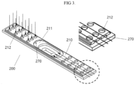
- FIG. 3 illustrates a perspective view of the spacer 200 of the secondary battery 100 shown in FIG. 1
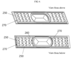
- FIG. 4 illustrates a view of the spacer 200 shown in FIG. 3 viewed from various angles.
- the spacer 200 has a surface portion (e.g., an upper surface) 210 that is in contact with the electrode assembly 110 and a space portion (e.g., a space or a void) 230 below the surface portion 210.
- a structure of the spacer 200 will be described in more detail.
- the surface portion 210 of the spacer 200 is a portion that is in contact with the electrode assembly 110 and may have a flat plate shape.
- An opening 211 is defined in the surface portion 210 of the spacer 200 in an area corresponding to the vent part 170, for example, in a longitudinal center portion of the spacer 200. Because the vent part 170 is exposed to the inside of the case 130 through the opening 211, if a cell event occurs in the secondary battery 100, a gas may flow directly into the vent part 170 to be discharged from the case 130.
- At least one gas discharge hole (e.g., at least one gas discharge opening) 212 is defined in the surface portion 210 around the opening 211.
- the gas discharge hole 212 may be defined to pass through the surface portion 210 of the spacer 200 and may be provided in plurality arranged in (e.g., adjacent to each other in) longitudinal and transverse directions in the surface portion 210.
- twelve gas discharge holes 212 are formed at each side of the opening 211 in the longitudinal direction of the spacer 200.
- the space portion 230 may be defined below the gas discharge hole 212, and the gas generated in the case 130 may be disposed to the outside through the vent part 170 via the space portion 230 and the gas discharge hole 212.
- the spacer 200 may have an outer wall 250 that protrudes downwardly from a circumference (or periphery) of the surface portion 210.
- the outer wall 250 may be continuously disposed along a long side and a short side of the spacer 200.
- the spacer 200 may have an inner wall 260 that similarly protrudes downwardly around the opening 211.
- the surface portion 210 may be spaced apart from (e.g., may form a gap between) the bottom surface of the case 130 by the outer wall 250 and the inner wall 260, and the gap may be the space portion 230. That is, the space portion 230 may be surrounded by (or may be formed by or between) the surface portion 210, the outer wall 250, the inner wall 260, and the lower bottom surface of the case 130.
- At least one gas discharge hole 212 may be provided to vertically pass through the surface portion 210, and thus, as indicated by the vertical arrows in FIG. 3 , a gas movement passage may be provided in a vertical direction.
- the gas movement passage may also be provided in a horizontal direction as indicated by the horizontal arrows in FIG. 3 .
- a plurality of exhaust holes 270 may be provided in the spacer 200, and the spacer 200 may be disposed to be spaced a distance (e.g., a predetermined distance) from the longitudinal inner surface of the case 130.
- the plurality of exhaust holes 270 may be defined in the outer wall 250 disposed on the short side of the spacer 200. In some embodiments, the plurality of exhaust holes 270 may also be provided in the inner wall 260. For example, in the embodiment illustrated in FIG. 3 , three exhaust holes 270 may be provided in each of the outer wall 250 and the inner wall 260. As described above, because the outer wall 250 is continuously disposed along the long side of the spacer 200, the gas may not flow between the outer wall 250 and the bottom surface of the case 130 in the longitudinal direction of the spacer 200. In some embodiments, the outer wall 250 may be continuously disposed along the short side of the spacer 200, but an exhaust hole 270 may be provided in the short side to provide a movement passage for gas.
- the short side of the spacer 200 may be disposed to be spaced a distance (e.g., a predetermined distance) from the longitudinal inner surface of the case 130. Due to this structure, as illustrated in FIG. 2 , the gas in the case 130 may pass through the exhaust hole 270 provided in the short side through the space between the inner surface of the case 130 and the short side of the spacer 200 to be introduced into the space portion 230 and then discharged to the outside through the vent part 170.
- a distance e.g., a predetermined distance
- the exhaust holes 270 in the outer wall 250 and the exhaust holes 270 in the inner wall 260 may be formed in one-to-one correspondence with each other, and the corresponding exhaust holes 270 may be arranged in a straight line.
- the same number of exhaust holes 270 may be provided in the inner wall 260 and the outer wall 250, and the facing exhaust holes 270 may be arranged in a straight line to induce a straight flow of the gas.
- the gas introduced through the exhaust hole 270 of the outer wall 250 may be discharged to the exhaust hole 270 in the inner wall 260 without causing an eddy current within the space portion 230 or while generating a minimal eddy current within the space 230.
- the gas discharge holes 212 arranged in the longitudinal direction along the surface portion 210 may be disposed above a straight line (or a straight path) connecting (e.g., fluidly connecting) the exhaust hole 270 of the outer wall 250 to the exhaust hole 270 of the inner wall 260.
- a straight line or a straight path
- the gas introduced in the vertical direction through the gas discharge hole 212 may be discharged to the exhaust hole 270 in the inner wall 260 while generating a minimum eddy current by being combined with the above-described straight flow.
- the gas movement passage may be provided in a spacer
- the gas discharge hole 212 may be provided in a plane of the spacer 200 to induce the discharge of the gas in the vertical direction
- the exhaust hole 270 may be provided in the side surface of the spacer 200 to induce the discharge of the gas in the horizontal direction.
- the spacer 200 provided in the secondary battery 100 may both fix the electrode assembly 110 while also acting as the gas exhaust passage.
- the left side image shows an experimental result of a gas flow in a secondary battery to which a related art spacer that does not have the gas discharge passage is applied
- the right side image shows an experimental result of a gas flow in a secondary battery that is provided with the spacer according to an embodiment of the present disclosure.
- the spacer according to an embodiment of the present disclosure has the exhaust hole in the side surface to allow the horizontal discharge of the gas, the gas flows evenly and actively in the horizontal direction of the spacer.
- the spacer both fixes the electrode assembly and also allows for gas discharge to be smoothly performed through the vent part provided at the lower end of the case through the discharge passage provided in the spacer.
Landscapes
- Chemical & Material Sciences (AREA)
- Chemical Kinetics & Catalysis (AREA)
- Electrochemistry (AREA)
- General Chemical & Material Sciences (AREA)
- Gas Exhaust Devices For Batteries (AREA)
- Sealing Battery Cases Or Jackets (AREA)
- Cell Separators (AREA)
Abstract
A secondary battery includes: an electrode assembly; a case accommodating the electrode assembly; a cap plate coupled to an opening in the case; and a spacer in the case. The case has a vent part extending through a surface facing the cap plate, and the spacer is accommodated in the case between a lower portion of the electrode assembly and the vent part. The spacer has: a surface portion contacting the electrode assembly and a space portion below the surface portion; an opening in an area of the surface portion corresponding to the vent part; and a gas discharge hole extending around the opening. Gas generated in the case is discharged to the outside through the vent part via the space portion and the gas discharge hole in the spacer.
Description
- Aspects of embodiments of the present disclosure relate to a secondary battery.
- Secondary batteries are designed to be chargeable and dischargeable, unlike primary batteries.
- Small-capacity secondary batteries may be used in small, portable electronic devices, such as mobile phones, laptop computers, and camcorders, while high-capacity secondary batteries may be used as power sources for driving motors in hybrid vehicles and electric vehicles.
- Generally, a secondary battery includes an electrode assembly that performs a charging/discharging operation, a case accommodating the electrode assembly, a cap plate coupled to an opening in the case, and an electrode terminal that draws the electrode assembly to the outside of the cap plate.
- In some secondary batteries, a vent part is provided in the case, which is designed to burst in response to increased pressure inside the case before another portion of the case bursts, thereby ensuring the safe flow of gas away from the secondary battery. Generally, the vent part is provided on an upper surface of the case adjacent to the electrode terminal. Recent secondary battery designs have placed the vent part at a bottom of the case opposite to the electrode terminal, also referred to as a downward vent structure. However, a spacer is often included at the bottom of the case to fix the jelly-roll electrode assembly, and the spacer can impede the smooth flow of gas from inside the case to outside the case through the vent part when it is arranged in the bottom of the case.
- The above-described information disclosed in the technology that serves as the background of the present disclosure is for improving understanding of the background of the present disclosure and, thus, may include information that does not constitute the related art.
- Embodiments of the present disclosure provide a secondary battery including a spacer that fixes (e.g., fixes a position of) an electrode assembly and has (or provides) a discharge passage for the smooth discharge of a gas when a vent part is disposed at a lower portion of a case opposite to an electrode terminal, also known as a downward vent structure.
- However, aspects and features of the present disclosure are not limited to those described above, and other aspects and features not mentioned will be clearly understood by those skilled in the art from the description of the present disclosure described below.
- According to an embodiment of the present disclosure, a secondary battery includes: an electrode assembly; a case accommodating the electrode assembly; a cap plate coupled to an opening in the case; and a spacer in the case. The case has a vent part extending through a surface facing the cap plate, and the spacer is accommodated in the case between a lower portion of the electrode assembly and the vent part. The spacer has: a surface portion contacting the electrode assembly and a space portion below the surface portion; an opening in an area of the surface portion corresponding to the vent part; and a gas discharge hole extending around the opening. Gas generated in the case is discharged to the outside through the vent part via the space portion and the gas discharge hole in the spacer.
- The gas discharge hole may extend through the surface portion of the spacer and may be provided in plurality, and the plurality of gas discharge holes may be arranged in longitudinal and transverse directions in the surface portion.
- The spacer may have an outer wall protruding downwardly along a periphery of the surface portion and an inner wall protruding downwardly along a periphery of the opening in the spacer. The surface portion may be spaced apart from a lower bottom surface of the case in which the vent part is formed by the outer wall and the inner wall, and the space portion may be surrounded by the surface portion, the outer wall, the inner wall, and the lower bottom surface of the case.
- The outer wall may be continuously arranged along a long side and a short side of the spacer, a plurality of exhaust holes may be in the outer wall and the inner wall on the short side, and the inside of the case may communicate with the space portion of the spacer via the exhaust holes.
- The exhaust holes in the outer wall and the exhaust holes in the inner wall may be in one-to-one correspondence with each other, and the corresponding exhaust holes may be arranged in a straight line.
- The gas discharge holes arranged in the longitudinal direction may be arranged above a straight path that connects the exhaust holes in the outer wall to the exhaust holes in the inner wall.
- The spacer may be spaced a distance from an inner surface of the case in the longitudinal direction.
- At least some of the above and other features of the invention are set out in the claims.
- The following drawings attached to this specification illustrate embodiments of the present disclosure to further describe aspects and features of the present disclosure along with the detailed description of the present disclosure, and thus, the present disclosure should not be limited to the embodiments illustrated in the drawings. In the drawings:
-
FIG. 1 illustrates a projective perspective view of a secondary battery according to embodiments; -
FIG. 2 illustrates a cross-sectional view of the secondary battery shown inFIG. 1 ; -
FIG. 3 illustrates a perspective view of a spacer of the secondary battery shown inFIG. 1 ; -
FIG. 4 illustrates a view of the spacer shown inFIG. 3 from different angles. -
FIG. 5 is a comparative view of results of an experiment on flow distribution of a gas in secondary batteries including a spacer according to the related art and a spacer according to an embodiment of the present disclosure; -
FIG. 6A illustrates a perspective view of a secondary battery according to the related art; -
FIG. 6B illustrates a projective perspective view of a secondary battery according to the related art; and -
FIG. 6C illustrates a cross-sectional view of the related art secondary battery shown inFIG. 6B . - Hereinafter, embodiments of the present disclosure will be described below in more detail with reference to the accompanying drawings. The terms used in the following description and claims are not limited to their dictionary meanings but are merely used to enable a clear and consistent understanding of the present disclosure. Accordingly, it should be apparent to those skilled in the art that the following description of embodiments of the present disclosure is provided for illustration purposes and not for the purpose of limiting the present disclosure, which is defined by the appended claims and their equivalents. Thus, because the embodiments described in this specification and the configurations shown in the drawings are only some embodiments of the present disclosure and do not represent all of the embodiments, aspects, or features of the present disclosure, it should be understood that there may be various equivalents and modifications that can be substituted for them at the time of this application.
- It will be understood that when an element or layer is referred to as being "on," "connected to," or "coupled to" another element or layer, it may be directly on, connected, or coupled to the other element or layer or one or more intervening elements or layers may also be present. When an element or layer is referred to as being "directly on," "directly connected to," or "directly coupled to" another element or layer, there are no intervening elements or layers present. For example, when a first element is described as being "coupled" or "connected" to a second element, the first element may be directly coupled or connected to the second element or the first element may be indirectly coupled or connected to the second element via one or more intervening elements.
- In the figures, dimensions of the various elements, layers, etc. may be exaggerated for clarity of illustration. The same reference numerals designate the same elements. As used herein, the term "and/or" includes any and all combinations of one or more of the associated listed items. Further, the use of "may" when describing embodiments of the present disclosure relates to "one or more embodiments of the present disclosure." Expressions, such as "at least one of" and "any one of," when preceding a list of elements, modify the entire list of elements and do not modify the individual elements of the list. For example, the expression "at least one of a, b, or c" indicates only a, only b, only c, both a and b, both a and c, both b and c, all of a, b, and c, or variations thereof. As used herein, the terms "use," "using," and "used" may be considered synonymous with the terms "utilize," "utilizing," and "utilized," respectively. As used herein, the terms "substantially," "about," and similar terms are used as terms of approximation and not as terms of degree, and are intended to account for the inherent variations in measured or calculated values that would be recognized by those of ordinary skill in the art.
- It will be understood that, although the terms first, second, third, etc. may be used herein to describe various elements, components, regions, layers, and/or sections, these elements, components, regions, layers, and/or sections should not be limited by these terms. These terms are used to distinguish one element, component, region, layer, or section from another element, component, region, layer, or section. Thus, a first element, component, region, layer, or section discussed below could be termed a second element, component, region, layer, or section without departing from the teachings of example embodiments.
- Spatially relative terms, such as "beneath," "below," "lower," "above," "upper," and the like, may be used herein for ease of description to describe one element or feature's relationship to another element(s) or feature(s) as illustrated in the figures. It will be understood that the spatially relative terms are intended to encompass different orientations of the device in use or operation in addition to the orientation depicted in the figures. For example, if the device in the figures is turned over, elements described as "below" or "beneath" other elements or features would then be oriented "above" or "over" the other elements or features. Thus, the term "below" may encompass both an orientation of above and below. The device may be otherwise oriented (rotated 90 degrees or at other orientations), and the spatially relative descriptors used herein should be interpreted accordingly.
- The terminology used herein is for the purpose of describing embodiments of the present disclosure and is not intended to be limiting of the present disclosure. As used herein, the singular forms "a" and "an" are intended to include the plural forms as well, unless the context clearly indicates otherwise. It will be further understood that the terms "includes," "including," "comprises," and/or "comprising," when used in this specification, specify the presence of stated features, integers, steps, operations, elements, and/or components but do not preclude the presence or addition of one or more other features, integers, steps, operations, elements, components, and/or groups thereof.
- In some embodiments of the [cylindrical/prismatic/pouch]-type battery according to an embodiment of the present disclosure, one of the prismatic/pouch/circular batteries is selected, and the selected battery is described as having a general structure, and for commonly applied technologies, the general structure of prismatic/pouch/round cells is described.
- Referring to
FIG. 6A , which shows a secondary battery according to a comparative example, avent part 17 may be provided in thecase 15 of the secondary battery. In thevent part 17, a vent plate may be coupled to a lower portion of a vent hole defined in thecase 15. Because the vent plate is thinner than a portion of thecase 15, if an internal pressure of thecase 15 increases due to overcharging, the vent plate is broken (or bursts) before other portions of thecase 15 to discharge the high-temperature gas and pressure to the outside, thereby ensuring safety of the secondary battery. - Referring to
FIGS. 6B and6C , a structure in which thevent part 17 is disposed on a bottom surface of thecase 15 instead of at an upper portion of thecase 15 has been proposed. For example, thevent part 17 is disposed at a side of thecase 15 opposite to theelectrode terminals case 15, and a notched vent plate is sealed and coupled to the vent hole. If a high-pressure gas is generated inside the secondary battery, the vent plate disposed at the lower portion of thecase 15 is broken (e.g., bursts) to cause a pressure difference inside and outside the case, and thus, the gas moves toward a lower side of thecase 15 due to the pressure difference and is then discharged to the outside through the vent hole. - A
spacer 20 may be interposed between a lower end of theelectrode assembly 10 and the bottom surface of thecase 15. Thespacer 20 fixes a jelly-roll electrode assembly 10 so that it is not shaken or moved within thecase 15. In addition, thespacer 20 is made of an insulating material to maintain insulation between theelectrode assembly 10 and thecase 15 and protects theelectrode assembly 10 by buffering an external impact. - However, when the
vent part 17 is disposed on a bottom surface of thecase 15, thespacer 20 disposed on the bottom surface of thecase 15 covers thevent part 17, thereby blocking a gas discharge path toward thevent part 17 and causing restriction in smooth gas discharge. Furthermore, because thespacer 20 does not have a separate gas flow path, it is difficult to smoothly discharge the gas. - In this case, there is a risk that an internal pressure of the cell rises rapidly and causes explosion of a welded surface of the secondary battery, thereby accelerating explosion of surrounding cells. Thus, a flow path should be ensured to provide for smooth gas discharge.
- As illustrated in
FIGS. 1 and2 , asecondary battery 100 according to embodiments of the present disclosure includes anelectrode assembly 110, acase 130, and acap plate 150. - The
electrode assembly 110 may be provided by winding or stacking a stack of a first electrode plate, a separator, and a second electrode plate, each of which is provided in a thin plate or film shape. If theelectrode assembly 110 is a rolled stack, a winding axis may be parallel to a longitudinal direction of thecase 130. In some embodiments, theelectrode assembly 110 may be a stack type rather than a winding type, and the shape of theelectrode assembly 110 is not limited to the embodiments. In some embodiments, theelectrode assembly 110 may include a Z-stack electrode assembly 110 in which a positive electrode plate and a negative electrode plate are inserted into both sides of the separator, which is bent in the form of a Z-stack. In some embodiments, theelectrode assembly 110 may be stacked so that one ormore electrode assemblies 110 are adjacent to each other and are accommodated in thecase 130. In some embodiments, the number ofelectrode assemblies 110 may not be limited thereto. In some embodiments, the first electrode plate of theelectrode assembly 110 may act as a negative electrode, and the second electrode plate may act as a positive electrode. In other embodiments, the first electrode plate may act as a positive electrode, and the second electrode plate may act as a negative electrode. - The first electrode plate may be formed by applying a first electrode active material, such as graphite or carbon, to a first electrode current collector plate made of a metal foil, such as copper, a copper alloy, nickel, or a nickel alloy. The first electrode plate may include a first electrode tab (e.g., a first non-coating portion) that is a portion of the first electrode current collector plate not coated with the first electrode active material. The first electrode tab may act as a path for a current flow between the first electrode plate and a first current collector. In some embodiments, the first electrode tab may be provided by being cut in advance to protrude to one side when the first electrode plate is manufactured and may protrude more to one side than (e.g., may protrude beyond) a separator without separate cutting.
- The second electrode plate may be provided by applying a second electrode active material, such as transition metal oxide, to a second electrode current collector plate made of metal foil, such as aluminium or an aluminium alloy. The second electrode plate may include a second electrode tab (e.g., a second non-coating portion) that is a portion of the second electrode current collector not coated with the second electrode active material. The second electrode tab may be a passage through which current flow between the second electrode plate and a second current collector. In some embodiments, the second electrode tab may be provided by being cut in advance to protrude to the other side when the second electrode plate is manufactured and may protrude more to the other side than (e.g., may protrude beyond) the separator without separate cutting.
- In some embodiments, the first electrode tab may be disposed on a side surface at a left end of the
electrode assembly 110, and the second electrode tab may be disposed on a side surface at a right end of theelectrode assembly 110 or may disposed on one surface in the same direction as the first electrode tab. InFIG. 2 , an embodiment in which the left and right sides of theelectrode assembly 110 are, for convenience of explanation, based on thesecondary battery 100 is illustrated, but the position of thesecondary battery 100 may be changed when thesecondary battery 100 is rotated left and right or up and down. - A first electrode tab of the first electrode plate and a second electrode tab of the second electrode plate may be disposed on both ends (e.g., opposite ends) of the
electrode assembly 110 as described above, respectively. In some embodiments, theelectrode assembly 110 may be accommodated in thecase 130 together with an electrolyte. In some embodiments, in theelectrode assembly 110, the first current collector and the second current collector may be welded and connected to the first electrode tab of the first electrode plate and the second electrode tab of the second electrode plate, which are exposed at both sides, respectively. - Then, the
case 130 may accommodate theelectrode assembly 110. For example, thecase 130 may have a substantially rectangular parallelepiped shape to provide a space for accommodating theelectrode assembly 110 and the electrolyte therein and may have an opening connecting external and internal spaces to each other defined in one surface of the rectangular parallelepiped shape. The opening may allow theelectrode assembly 110 to be inserted into thecase 130. - However, the present disclosure is not limited thereto, and the
case 130 may have various, suitable shapes, such as a circular shape or a pouch shape. In some embodiments, thecase 130 may be made of a metal, such as aluminium, aluminium alloy, or nickel-plated steel, or may be a laminated film or plastic that constitutes the pouch or case. - The
cap plate 150 may be installed in the opening of thecase 130 to seal the opening in thecase 130. For example, thecase 130 and thecap plate 150 may be made of aluminium and welded to each other. - In some embodiments, the
cap plate 150 may further include terminal holes (e.g., terminal openings) H1 and H2 and an electrolyte injection port. The electrolyte injection port may allow the electrolyte to be injected into thecase 130 after coupling and welding thecap plate 150 to thecase 130. - Negative and
positive terminals electrode assembly 110 and installed in the terminal holes H1 and H2 in thecap plate 150. In some embodiments, the negative andpositive terminals positive terminals electrode assembly 110, respectively. In some embodiments, theelectrode assembly 110 may be drawn to the outside of thecase 130 through the negative andpositive terminals - A
vent part 170 may be defined to pass through a surface of thecase 130 opposite to thecap plate 150. For example, thecap plate 150 may be coupled to an upper opening in thecase 130, and thevent part 170 may be provided in a lower, bottom surface of thecase 130 opposite to thecap plate 150 on thecase 130. A high-temperature gas and pressure, which are generated inside thecase 130, may be discharged to the outside of thecase 130 through thevent part 170. In some embodiments, thevent part 170 may have a vent hole (e.g., a vent opening) and a vent plate sealed and coupled around (or to) the vent hole. A recess part may be provided in the above-described vent part formation surface of thecase 130, for example, in the lower bottom surface, and the vent hole may be defined inside the recess part. The vent plate may seal the vent hole and may be installed so that if a cell event (e.g., a thermal runaway) occurs, the vent plate is cut (or bursts) to discharge the internal pressure of thesecondary battery 100. In some embodiments, if the internal pressure reaches a reference (or set) pressure, the vent plate may be cut (or may burst) to open the vent hole. The vent plate may have a notch that guides (or facilitates) the cutting (or bursting). - As illustrated in
FIG. 2 , aspacer 200 is disposed between the lower portion (or lower surface) of theelectrode assembly 110 and thevent part 170, that is, between theelectrode assembly 110 and the vent part formation surface in thecase 130. When theelectrode assembly 110 is accommodated in thecase 130, a clearance may occur (e.g., a space may be present) between the lower end of theelectrode assembly 110 and the vent formation surface of thecase 130, that is, the lower bottom surface of thecase 130, and thespacer 200 may be interposed into the clearance space to fix theelectrode assembly 110 within thecase 130 to prevent theelectrode assembly 110 from being shaken and to suppress vibration in a height direction. In some embodiments, thespacer 200 may be made of a material having electrolyte resistance and absorbs an external impact due to characteristics or morphological characteristics of the material itself. In addition, thespacer 200 may be made of an insulating material to maintain insulation (e.g., electrical insulation) between theelectrode assembly 110 and thecase 130. -
FIG. 3 illustrates a perspective view of thespacer 200 of thesecondary battery 100 shown inFIG. 1 , andFIG. 4 illustrates a view of thespacer 200 shown inFIG. 3 viewed from various angles. Referring toFIGS. 3 and4 , thespacer 200 has a surface portion (e.g., an upper surface) 210 that is in contact with theelectrode assembly 110 and a space portion (e.g., a space or a void) 230 below thesurface portion 210. Hereinafter, a structure of thespacer 200 will be described in more detail. - The
surface portion 210 of thespacer 200 is a portion that is in contact with theelectrode assembly 110 and may have a flat plate shape. Anopening 211 is defined in thesurface portion 210 of thespacer 200 in an area corresponding to thevent part 170, for example, in a longitudinal center portion of thespacer 200. Because thevent part 170 is exposed to the inside of thecase 130 through theopening 211, if a cell event occurs in thesecondary battery 100, a gas may flow directly into thevent part 170 to be discharged from thecase 130. - At least one gas discharge hole (e.g., at least one gas discharge opening) 212 is defined in the
surface portion 210 around theopening 211. Thegas discharge hole 212 may be defined to pass through thesurface portion 210 of thespacer 200 and may be provided in plurality arranged in (e.g., adjacent to each other in) longitudinal and transverse directions in thesurface portion 210. For example, in the embodiment illustrated inFIG. 3 , twelve gas discharge holes 212 are formed at each side of theopening 211 in the longitudinal direction of thespacer 200. - The
space portion 230 may be defined below thegas discharge hole 212, and the gas generated in thecase 130 may be disposed to the outside through thevent part 170 via thespace portion 230 and thegas discharge hole 212. Referring toFIGS. 2 to 4 , thespacer 200 may have anouter wall 250 that protrudes downwardly from a circumference (or periphery) of thesurface portion 210. Theouter wall 250 may be continuously disposed along a long side and a short side of thespacer 200. In some embodiments, thespacer 200 may have aninner wall 260 that similarly protrudes downwardly around theopening 211. Thesurface portion 210 may be spaced apart from (e.g., may form a gap between) the bottom surface of thecase 130 by theouter wall 250 and theinner wall 260, and the gap may be thespace portion 230. That is, thespace portion 230 may be surrounded by (or may be formed by or between) thesurface portion 210, theouter wall 250, theinner wall 260, and the lower bottom surface of thecase 130. - As described above, at least one
gas discharge hole 212 may be provided to vertically pass through thesurface portion 210, and thus, as indicated by the vertical arrows inFIG. 3 , a gas movement passage may be provided in a vertical direction. - According to some embodiments, the gas movement passage may also be provided in a horizontal direction as indicated by the horizontal arrows in
FIG. 3 . In some embodiments, a plurality ofexhaust holes 270 may be provided in thespacer 200, and thespacer 200 may be disposed to be spaced a distance (e.g., a predetermined distance) from the longitudinal inner surface of thecase 130. - In some embodiments, the plurality of
exhaust holes 270 may be defined in theouter wall 250 disposed on the short side of thespacer 200. In some embodiments, the plurality ofexhaust holes 270 may also be provided in theinner wall 260. For example, in the embodiment illustrated inFIG. 3 , threeexhaust holes 270 may be provided in each of theouter wall 250 and theinner wall 260. As described above, because theouter wall 250 is continuously disposed along the long side of thespacer 200, the gas may not flow between theouter wall 250 and the bottom surface of thecase 130 in the longitudinal direction of thespacer 200. In some embodiments, theouter wall 250 may be continuously disposed along the short side of thespacer 200, but anexhaust hole 270 may be provided in the short side to provide a movement passage for gas. In some embodiments, the short side of thespacer 200 may be disposed to be spaced a distance (e.g., a predetermined distance) from the longitudinal inner surface of thecase 130. Due to this structure, as illustrated inFIG. 2 , the gas in thecase 130 may pass through theexhaust hole 270 provided in the short side through the space between the inner surface of thecase 130 and the short side of thespacer 200 to be introduced into thespace portion 230 and then discharged to the outside through thevent part 170. - According to some embodiments, the exhaust holes 270 in the
outer wall 250 and the exhaust holes 270 in theinner wall 260 may be formed in one-to-one correspondence with each other, and the corresponding exhaust holes 270 may be arranged in a straight line. The same number ofexhaust holes 270 may be provided in theinner wall 260 and theouter wall 250, and the facing exhaust holes 270 may be arranged in a straight line to induce a straight flow of the gas. As a result, the gas introduced through theexhaust hole 270 of theouter wall 250 may be discharged to theexhaust hole 270 in theinner wall 260 without causing an eddy current within thespace portion 230 or while generating a minimal eddy current within thespace 230. - In some embodiments, the gas discharge holes 212 arranged in the longitudinal direction along the
surface portion 210 may be disposed above a straight line (or a straight path) connecting (e.g., fluidly connecting) theexhaust hole 270 of theouter wall 250 to theexhaust hole 270 of theinner wall 260. As a result, the gas introduced in the vertical direction through thegas discharge hole 212 may be discharged to theexhaust hole 270 in theinner wall 260 while generating a minimum eddy current by being combined with the above-described straight flow. - According to embodiments of the present disclosure, the gas movement passage may be provided in a spacer, the
gas discharge hole 212 may be provided in a plane of thespacer 200 to induce the discharge of the gas in the vertical direction, and theexhaust hole 270 may be provided in the side surface of thespacer 200 to induce the discharge of the gas in the horizontal direction. In some embodiments, thespacer 200 provided in thesecondary battery 100 may both fix theelectrode assembly 110 while also acting as the gas exhaust passage. - Referring to
FIG. 5 , the left side image shows an experimental result of a gas flow in a secondary battery to which a related art spacer that does not have the gas discharge passage is applied, and the right side image shows an experimental result of a gas flow in a secondary battery that is provided with the spacer according to an embodiment of the present disclosure. As can be seen, because the spacer according to an embodiment of the present disclosure has the exhaust hole in the side surface to allow the horizontal discharge of the gas, the gas flows evenly and actively in the horizontal direction of the spacer. - According to some embodiments, the spacer both fixes the electrode assembly and also allows for gas discharge to be smoothly performed through the vent part provided at the lower end of the case through the discharge passage provided in the spacer.
- However, the aspects and features of the present disclosure are not limited to the above-described aspects and features, and other aspects and features not mentioned can be clearly understood by those skilled in the art from the description of the present disclosure and the claims and their equivalents.
- As described above, while embodiments of the present disclosure have been described herein, it will be apparent to those skilled in the art that various changes and modifications may be made without departing from the scope of the present disclosure as defined in the following claims and their equivalents.
- Embodiments are set out in the following clauses:
- Clause 1. A secondary battery comprising:
- an electrode assembly;
- a case configured to accommodate the electrode assembly; and
- a cap plate coupled to one opening of the case,
- wherein a vent part is provided to be penetrated in a surface facing the cap plate of the case, and a spacer is disposed in the case between a lower portion of the electrode assembly and the vent part,
- the spacer comprises a surface portion that is in contact with the electrode assembly and a space portion below the surface portion,
- an opening is defined in an area of the surface portion of the spacer, which corresponds to the vent part, and at least one gas discharge hole is defined around the opening, and
- a gas generated in the case is discharged to the outside through the vent part via the space portion through the gas discharge hole of the spacer.
- Clause 2. The secondary battery of clause 1, wherein the gas discharge hole is defined to pass through a surface portion of the spacer and is provided in plurality, which are arranged in longitudinal and transverse directions in the surface portion.
- Clause 3. The secondary battery of clause 2, wherein the spacer comprises an outer wall protruding downward from a circumference of the surface portion and an inner wall protruding downward from a circumference of the opening, and
the surface portion is spaced apart from a lower bottom surface of the case, in which the vent part is provided, by the outer wall and the inner wall, and the space portion is surrounded by the surface portion, the outer wall, the inner wall, and the lower bottom surface. - Clause 4. The secondary battery of clause 3, wherein the outer wall is continuously disposed on a long side and a short side of the spacer,
- a plurality of exhaust holes are provided in the outer wall and the inner wall disposed on the short side, and
- the inside of the case communicates with the space portion of the spacer by the exhaust holes.
- Clause 5. The secondary battery of clause 4, wherein the exhaust hole of the outer wall and the exhaust holes of the inner wall one-to-one correspond to each other, andthe corresponding exhaust holes are arranged in a straight line.
- Clause 6. The secondary battery of clause 5, wherein the gas discharge holes arranged in the longitudinal direction are disposed above a straight line that connects the exhaust holes of the outer wall to the exhaust holes of the inner wall.
- Clause 7. The secondary battery of any one of clauses 3 to 6, wherein the spacers are disposed to be spaced a predetermined distance from an inner surface of the case in the longitudinal direction.
Claims (7)
- A secondary battery comprising:an electrode assembly;a case accommodating the electrode assembly;a cap plate coupled to an opening in the case; anda spacer in the case,wherein the case has a vent part extending through a surface facing the cap plate,wherein the spacer is accommodated in the case between a lower portion of the electrode assembly and the vent part,wherein the spacer has:a surface portion contacting the electrode assembly and a space portion below the surface portion;an opening in an area of the surface portion corresponding to the vent part; anda gas discharge hole extending around the opening, andwherein gas generated in the case is discharged to the outside through the vent part via the space portion and the gas discharge hole in the spacer.
- The secondary battery as claimed in claim 1, wherein the gas discharge hole extends through the surface portion of the spacer and is provided in plurality, and
wherein the plurality of gas discharge holes are arranged in longitudinal and transverse directions in the surface portion. - The secondary battery as claimed in claim 2, wherein the spacer has an outer wall protruding downwardly along a periphery of the surface portion and an inner wall protruding downwardly along a periphery of the opening in the spacer,wherein the surface portion is spaced apart from a lower bottom surface of the case in which the vent part is formed by the outer wall and the inner wall, andwherein the space portion is surrounded by the surface portion, the outer wall, the inner wall, and the lower bottom surface of the case.
- The secondary battery as claimed in claim 3, wherein the outer wall is continuously arranged along a long side and a short side of the spacer,wherein a plurality of exhaust holes are in the outer wall and the inner wall on the short side, andwherein the inside of the case communicates with the space portion of the spacer via the exhaust holes.
- The secondary battery as claimed in claim 4, wherein the exhaust holes in the outer wall and the exhaust holes in the inner wall are in one-to-one correspondence with each other, and
wherein the corresponding exhaust holes are arranged in a straight line. - The secondary battery as claimed in claim 5, wherein the gas discharge holes arranged in the longitudinal direction are arranged above a straight path that connects the exhaust holes in the outer wall to the exhaust holes in the inner wall.
- The secondary battery as claimed in any one of claims 3 to 6, wherein the spacer is spaced a distance from an inner surface of the case in the longitudinal direction.
Applications Claiming Priority (1)
| Application Number | Priority Date | Filing Date | Title |
|---|---|---|---|
| KR1020230152311A KR20250066603A (en) | 2023-11-07 | 2023-11-07 | Secondary battery |
Publications (1)
| Publication Number | Publication Date |
|---|---|
| EP4553978A1 true EP4553978A1 (en) | 2025-05-14 |
Family
ID=91923866
Family Applications (1)
| Application Number | Title | Priority Date | Filing Date |
|---|---|---|---|
| EP24188136.6A Pending EP4553978A1 (en) | 2023-11-07 | 2024-07-11 | Secondary battery |
Country Status (5)
| Country | Link |
|---|---|
| US (1) | US20250149740A1 (en) |
| EP (1) | EP4553978A1 (en) |
| JP (1) | JP7815348B2 (en) |
| KR (1) | KR20250066603A (en) |
| CN (1) | CN119965467A (en) |
Citations (2)
| Publication number | Priority date | Publication date | Assignee | Title |
|---|---|---|---|---|
| EP3503250A1 (en) * | 2016-08-18 | 2019-06-26 | Samsung SDI Co., Ltd. | Rechargeable battery |
| EP4148889A1 (en) * | 2021-07-29 | 2023-03-15 | Contemporary Amperex Technology Co., Limited | Battery cell, fabrication method and fabrication system therefor, battery, and electric apparatus |
Family Cites Families (3)
| Publication number | Priority date | Publication date | Assignee | Title |
|---|---|---|---|---|
| CN118738751A (en) | 2023-03-31 | 2024-10-01 | 宁德时代新能源科技股份有限公司 | Battery cells, batteries and electrical devices |
| CN116706416B (en) | 2023-08-07 | 2023-10-13 | 蜂巢能源科技股份有限公司 | Power battery and battery pack |
| CN118073764B (en) | 2024-02-04 | 2025-02-11 | 欣旺达动力科技股份有限公司 | Battery cells, battery packs and electrical equipment |
-
2023
- 2023-11-07 KR KR1020230152311A patent/KR20250066603A/en active Pending
-
2024
- 2024-04-12 US US18/634,746 patent/US20250149740A1/en active Pending
- 2024-07-11 EP EP24188136.6A patent/EP4553978A1/en active Pending
- 2024-07-16 CN CN202410950281.0A patent/CN119965467A/en active Pending
- 2024-07-19 JP JP2024115317A patent/JP7815348B2/en active Active
Patent Citations (2)
| Publication number | Priority date | Publication date | Assignee | Title |
|---|---|---|---|---|
| EP3503250A1 (en) * | 2016-08-18 | 2019-06-26 | Samsung SDI Co., Ltd. | Rechargeable battery |
| EP4148889A1 (en) * | 2021-07-29 | 2023-03-15 | Contemporary Amperex Technology Co., Limited | Battery cell, fabrication method and fabrication system therefor, battery, and electric apparatus |
Also Published As
| Publication number | Publication date |
|---|---|
| KR20250066603A (en) | 2025-05-14 |
| JP2025077977A (en) | 2025-05-19 |
| US20250149740A1 (en) | 2025-05-08 |
| JP7815348B2 (en) | 2026-02-17 |
| CN119965467A (en) | 2025-05-09 |
Similar Documents
| Publication | Publication Date | Title |
|---|---|---|
| US11289782B2 (en) | Secondary battery | |
| US20040126650A1 (en) | Electrode assembly for lithium ion cell and lithium cell using the same | |
| EP3754750B1 (en) | Venting device | |
| US20080107961A1 (en) | Rechargeable battery | |
| KR100914115B1 (en) | Secondary battery | |
| EP4191760B1 (en) | Secondary battery | |
| US11276899B2 (en) | Rechargeable battery | |
| KR102885284B1 (en) | Rechargeable battery | |
| EP3712978B1 (en) | Secondary battery | |
| US20250266575A1 (en) | Electrode assembly and cylindrical secondary battery including the electrode assembly | |
| US20150024241A1 (en) | Rechargeable battery | |
| KR20230086276A (en) | secondary battery | |
| US20230223643A1 (en) | Secondary battery | |
| KR20240097710A (en) | Cylindrical battery cell, and battery pack and vehicle including the same and, method of producing cylindrical battery cell | |
| US20230268620A1 (en) | Secondary battery | |
| EP4553978A1 (en) | Secondary battery | |
| EP4632907A2 (en) | Battery pack | |
| US12362396B2 (en) | Secondary battery | |
| US20250158212A1 (en) | Secondary battery | |
| KR100731434B1 (en) | Secondary battery | |
| US20260038955A1 (en) | Secondary battery and method for manufacturing the same | |
| US20250239720A1 (en) | Rechargeable battery | |
| US20260051615A1 (en) | Secondary battery | |
| US20240332685A1 (en) | Secondary battery | |
| US20250293385A1 (en) | Battery cell and battery module including the same |
Legal Events
| Date | Code | Title | Description |
|---|---|---|---|
| PUAI | Public reference made under article 153(3) epc to a published international application that has entered the european phase |
Free format text: ORIGINAL CODE: 0009012 |
|
| STAA | Information on the status of an ep patent application or granted ep patent |
Free format text: STATUS: REQUEST FOR EXAMINATION WAS MADE |
|
| 17P | Request for examination filed |
Effective date: 20240711 |
|
| AK | Designated contracting states |
Kind code of ref document: A1 Designated state(s): AL AT BE BG CH CY CZ DE DK EE ES FI FR GB GR HR HU IE IS IT LI LT LU LV MC ME MK MT NL NO PL PT RO RS SE SI SK SM TR |