EP4553976A1 - Battery fire extinguishing device and operating method thereof - Google Patents
Battery fire extinguishing device and operating method thereof Download PDFInfo
- Publication number
- EP4553976A1 EP4553976A1 EP23855164.2A EP23855164A EP4553976A1 EP 4553976 A1 EP4553976 A1 EP 4553976A1 EP 23855164 A EP23855164 A EP 23855164A EP 4553976 A1 EP4553976 A1 EP 4553976A1
- Authority
- EP
- European Patent Office
- Prior art keywords
- fire
- resistor
- battery
- units
- voltage
- Prior art date
- Legal status (The legal status is an assumption and is not a legal conclusion. Google has not performed a legal analysis and makes no representation as to the accuracy of the status listed.)
- Granted
Links
Images



Classifications
-
- H—ELECTRICITY
- H01—ELECTRIC ELEMENTS
- H01M—PROCESSES OR MEANS, e.g. BATTERIES, FOR THE DIRECT CONVERSION OF CHEMICAL ENERGY INTO ELECTRICAL ENERGY
- H01M50/00—Constructional details or processes of manufacture of the non-active parts of electrochemical cells other than fuel cells, e.g. hybrid cells
- H01M50/20—Mountings; Secondary casings or frames; Racks, modules or packs; Suspension devices; Shock absorbers; Transport or carrying devices; Holders
- H01M50/233—Mountings; Secondary casings or frames; Racks, modules or packs; Suspension devices; Shock absorbers; Transport or carrying devices; Holders characterised by physical properties of casings or racks, e.g. dimensions
- H01M50/24—Mountings; Secondary casings or frames; Racks, modules or packs; Suspension devices; Shock absorbers; Transport or carrying devices; Holders characterised by physical properties of casings or racks, e.g. dimensions adapted for protecting batteries from their environment, e.g. from corrosion
-
- A—HUMAN NECESSITIES
- A62—LIFE-SAVING; FIRE-FIGHTING
- A62C—FIRE-FIGHTING
- A62C3/00—Fire prevention, containment or extinguishing specially adapted for particular objects or places
- A62C3/16—Fire prevention, containment or extinguishing specially adapted for particular objects or places in electrical installations, e.g. cableways
-
- A—HUMAN NECESSITIES
- A62—LIFE-SAVING; FIRE-FIGHTING
- A62C—FIRE-FIGHTING
- A62C35/00—Permanently-installed equipment
- A62C35/02—Permanently-installed equipment with containers for delivering the extinguishing substance
- A62C35/10—Containers destroyed or opened by flames or heat
-
- A—HUMAN NECESSITIES
- A62—LIFE-SAVING; FIRE-FIGHTING
- A62C—FIRE-FIGHTING
- A62C37/00—Control of fire-fighting equipment
- A62C37/08—Control of fire-fighting equipment comprising an outlet device containing a sensor, or itself being the sensor, i.e. self-contained sprinklers
- A62C37/10—Releasing means, e.g. electrically released
-
- G—PHYSICS
- G01—MEASURING; TESTING
- G01R—MEASURING ELECTRIC VARIABLES; MEASURING MAGNETIC VARIABLES
- G01R19/00—Arrangements for measuring currents or voltages or for indicating presence or sign thereof
- G01R19/165—Indicating that current or voltage is either above or below a predetermined value or within or outside a predetermined range of values
-
- H—ELECTRICITY
- H01—ELECTRIC ELEMENTS
- H01M—PROCESSES OR MEANS, e.g. BATTERIES, FOR THE DIRECT CONVERSION OF CHEMICAL ENERGY INTO ELECTRICAL ENERGY
- H01M10/00—Secondary cells; Manufacture thereof
- H01M10/42—Methods or arrangements for servicing or maintenance of secondary cells or secondary half-cells
-
- H—ELECTRICITY
- H01—ELECTRIC ELEMENTS
- H01M—PROCESSES OR MEANS, e.g. BATTERIES, FOR THE DIRECT CONVERSION OF CHEMICAL ENERGY INTO ELECTRICAL ENERGY
- H01M50/00—Constructional details or processes of manufacture of the non-active parts of electrochemical cells other than fuel cells, e.g. hybrid cells
- H01M50/50—Current conducting connections for cells or batteries
- H01M50/569—Constructional details of current conducting connections for detecting conditions inside cells or batteries, e.g. details of voltage sensing terminals
-
- H—ELECTRICITY
- H01—ELECTRIC ELEMENTS
- H01M—PROCESSES OR MEANS, e.g. BATTERIES, FOR THE DIRECT CONVERSION OF CHEMICAL ENERGY INTO ELECTRICAL ENERGY
- H01M50/00—Constructional details or processes of manufacture of the non-active parts of electrochemical cells other than fuel cells, e.g. hybrid cells
- H01M50/60—Arrangements or processes for filling or topping-up with liquids; Arrangements or processes for draining liquids from casings
- H01M50/673—Containers for storing liquids; Delivery conduits therefor
- H01M50/682—Containers for storing liquids; Delivery conduits therefor accommodated in battery or cell casings
-
- H—ELECTRICITY
- H02—GENERATION; CONVERSION OR DISTRIBUTION OF ELECTRIC POWER
- H02H—EMERGENCY PROTECTIVE CIRCUIT ARRANGEMENTS
- H02H3/00—Emergency protective circuit arrangements for automatic disconnection directly responsive to an undesired change from normal electric working condition with or without subsequent reconnection ; integrated protection
- H02H3/20—Emergency protective circuit arrangements for automatic disconnection directly responsive to an undesired change from normal electric working condition with or without subsequent reconnection ; integrated protection responsive to excess voltage
-
- H—ELECTRICITY
- H01—ELECTRIC ELEMENTS
- H01M—PROCESSES OR MEANS, e.g. BATTERIES, FOR THE DIRECT CONVERSION OF CHEMICAL ENERGY INTO ELECTRICAL ENERGY
- H01M10/00—Secondary cells; Manufacture thereof
- H01M10/42—Methods or arrangements for servicing or maintenance of secondary cells or secondary half-cells
- H01M10/48—Accumulators combined with arrangements for measuring, testing or indicating the condition of cells, e.g. the level or density of the electrolyte
-
- H—ELECTRICITY
- H01—ELECTRIC ELEMENTS
- H01M—PROCESSES OR MEANS, e.g. BATTERIES, FOR THE DIRECT CONVERSION OF CHEMICAL ENERGY INTO ELECTRICAL ENERGY
- H01M2200/00—Safety devices for primary or secondary batteries
-
- H—ELECTRICITY
- H01—ELECTRIC ELEMENTS
- H01M—PROCESSES OR MEANS, e.g. BATTERIES, FOR THE DIRECT CONVERSION OF CHEMICAL ENERGY INTO ELECTRICAL ENERGY
- H01M2220/00—Batteries for particular applications
- H01M2220/20—Batteries in motive systems, e.g. vehicle, ship, plane
-
- Y—GENERAL TAGGING OF NEW TECHNOLOGICAL DEVELOPMENTS; GENERAL TAGGING OF CROSS-SECTIONAL TECHNOLOGIES SPANNING OVER SEVERAL SECTIONS OF THE IPC; TECHNICAL SUBJECTS COVERED BY FORMER USPC CROSS-REFERENCE ART COLLECTIONS [XRACs] AND DIGESTS
- Y02—TECHNOLOGIES OR APPLICATIONS FOR MITIGATION OR ADAPTATION AGAINST CLIMATE CHANGE
- Y02E—REDUCTION OF GREENHOUSE GAS [GHG] EMISSIONS, RELATED TO ENERGY GENERATION, TRANSMISSION OR DISTRIBUTION
- Y02E60/00—Enabling technologies; Technologies with a potential or indirect contribution to GHG emissions mitigation
- Y02E60/10—Energy storage using batteries
Definitions
- Embodiments disclosed herein relate to a battery fire-extinguishing apparatus and an operating method thereof.
- Secondary batteries which are chargeable/dischargeable batteries, may include all of conventional nickel (Ni)/cadmium (Cd) batteries, Ni/metal hydride (MH) batteries, etc., and recent lithium-ion batteries.
- a lithium-ion battery has a much higher energy density than those of conventional Ni/Cd batteries, Ni/MH batteries, etc.
- the lithium-ion battery may be manufactured to be small and lightweight, such that the lithium-ion battery has been used as a power source of mobile devices, and recently, a use range thereof has been extended to power sources for electric vehicles, attracting attention as next-generation energy storage media.
- Embodiments disclosed herein aim to provide a battery fire-extinguishing apparatus and an operating method thereof in which when fire occurs in some battery module of a battery pack, ignition may be suppressed using fire-extinguishing fluid and heat spread to other battery modules may be prevented.
- a battery fire-extinguishing apparatus includes a plurality of fire-extinguishing fluid storing units respectively located in a plurality of battery modules and configured to discharge fire-extinguishing fluid by heating, a plurality of resistor units respectively adjacent to the plurality of fire-extinguishing fluid storing units, and a control circuit configured to monitor voltage across both ends of the plurality of resistor units and increase current flowing through each of the plurality of resistor units when the voltage is higher than a reference voltage.
- the plurality of resistor units may be electrically connected to one another in parallel, and each resistor unit may include a heating pad that is destroyed by heating to open the connected circuit.
- the voltage across the both ends of the plurality of resistor units may be higher than the reference voltage when the heating pad included in at least one of the plurality of resistor units is destroyed.
- a fire-extinguishing fluid storing unit adjacent to each resistor unit may be configured to discharge fire-extinguishing fluid by heating, when the current flowing through each of the plurality of resistor units increases.
- the fire-extinguishing fluid may include a material that prevents an electrolyte gas in the battery module from contacting oxygen and lowers a temperature in the battery module.
- the control circuit may include a comparator configured to compare the voltage across both ends of the plurality of resistor units with the reference voltage, a serial resistor serially connected to the plurality of resistor units, a power supply unit configured to supply power to the plurality of resistor units and the circuit connected to the serial resistor, and at least one switch configured to electrically connect or disconnect the plurality of resistor units to or from the serial resistor, in which, when the voltage across the both ends of the plurality of resistor units is higher than the reference voltage, electric connection between the plurality of resistors and the serial resistor is blocked to increase the current flowing through each of the plurality of resistor units.
- the serial resistor may have a greater resistance value than a total resistance value of the plurality of resistor units.
- control circuit may further include a regulator configured to maintain voltage supplied from the power supply unit at a certain level and supply the voltage to the comparator.
- An operating method of a battery fire-extinguishing apparatus includes monitoring voltage across both ends of a plurality of resistor units respectively adjacent to a plurality of fire-extinguishing fluid storing units respectively located in a plurality of battery modules and increasing current flowing through each of the plurality of resistor units when voltage is higher than a reference voltage.
- the increasing of the current flowing through each of the plurality of resistor units may include comparing the voltage across both ends of the plurality of resistor units with the reference voltage and controlling a switch circuit to block electric connection between the plurality of resistor units and a serial resistor having a greater resistance value than the plurality of resistor units, when the voltage across the both ends of the plurality of resistor units is higher than the reference voltage.
- the operating method of the battery fire-extinguishing apparatus may further include heating the plurality of resistor units and the fire-extinguishing fluid storing unit to discharge fire-extinguishing fluid from the fire-extinguishing fluid storing unit.
- fire-extinguishing fluid when fire occurs in some battery module of a battery pack, fire-extinguishing fluid may be automatically discharged to suppress fire ignition.
- fire-extinguishing fluid may be automatically discharged into all other battery modules to prevent heat from spreading to the other battery modules.
- FIG. 1 shows a structure of a battery module in which a battery fire-extinguishing apparatus according to an embodiment is installed.
- a battery pack used as a power source for an electronic device such as an electric vehicle, etc. includes a plurality of battery modules, each of which may include one or more battery cells.
- a battery cell is a component that is repeatedly chargeable/dischargeable and is capable of generating a potential difference through an electrochemical reaction.
- a battery cell may include a positive electrode, a negative electrode, a separator, and an electrolyte, and when internal short circuit occurs due to the absence of the separator, introduction of foreign metal substances, internal deformation, damage to the separator, etc., or overheating occurs due to abnormality of a control system, fire may occur due to a battery cell. Fire occurring in some battery cells may be spread to fire of other battery cells or battery modules where the battery cells are located, and fire occurring in some battery module may be spread to fire of other battery modules and the entire battery pack.
- a battery pack may include a plurality of battery modules M1, M2, M3, M4, ...
- a battery fire-extinguishing apparatus may include a plurality of fire-extinguishing fluid storing units P1, P2, P3, P4, ..., respectively located in the plurality of battery modules M1, M2, M3, M4, ..., a plurality of resistor units R1, R2, R3, R4, ..., adjacent respectively to the plurality of fire-extinguishing fluid storing units P1, P2, P3, P4, ..., and a control circuit 10 for controlling current flowing through the plurality of resistor units R1, R2, R3, R4, ....
- each fire-extinguishing fluid storing unit may include a pouch that bursts when heated at a certain temperature or more, and the fire-extinguishing fluid discharged from the fire-extinguishing fluid storing unit may include a material for preventing an electrolyte gas in the battery module from contacting oxygen to lower a temperature in the battery module.
- the fire-extinguishing fluid storing unit in the battery module may burst to discharge the fire-extinguishing fluid, thus suppressing fire ignition.
- the resistor units R1, R2, R3, R4, ... may be respectively disposed adjacent to the fire-extinguishing fluid storing units P1, P2, P3, P4, ..., and may be preferably attached to the surface of the fire-extinguishing fluid storing unit (pouch).
- the resistor units R1, R2, R3, R4, ... may be electrically connected to one another in parallel and resistance heat may be generated depending on current flowing through the resistor units.
- each resistor unit may include a heating pad that is destroyed when heated at a certain temperature or more, and opens a connected circuit when the heating pad is destroyed.
- the fire-extinguishing fluid storing unit P1 may burst to suppress fire ignition of the battery module M1 and at the same time other resistors R2, R3, R4, ... connected to the resistor R1 in parallel may be heated to burst adjacent fire-extinguishing fluid storing units P2, P3, P4, ..., thereby suppressing or preventing fire ignition of the other battery modules M2, M3, M4, ....
- the control circuit 10 may monitor voltage across both ends of the plurality of resistor units R1, R2, R3, R4, ... and increase current flowing through each resistor unit when the voltage is higher than a reference voltage, thereby inducing destruction of the fire-extinguishing fluid storing unit adjacent to each resistor unit. A detailed operating method of the control circuit 10 will be described later.
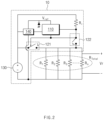
- FIG. 2 shows an equivalent circuit structure of a battery fire-extinguishing apparatus according to an embodiment.
- the control circuit 10 of the battery fire-extinguishing apparatus may include a comparator 110 for comparing voltage at both ends of the resistor units R1, R2, R3, ..., Rn with a reference voltage Vref, at least one switches 121 and 122 for electrically connecting or disconnecting a resistor unit to or from a serial resistor, and a power supply unit 130 for supplying power to the circuit.
- the comparator 110 may compare a voltage Vr across both ends of the resistor units R1, R2, R3, ..., Rn with the reference voltage Vref and open or close the switches 121 and 122 of the circuit according to a result of comparison to connect or disconnect a serial resistor Rr to or from the resistor units R1, R2, R3, ....
- the plurality of resistor units R1, R2, R3, ..., Rn may be connected to one another in parallel and all ends of the resistor units may be serially connected to the serial resistor Rr.
- the serial resistor Rr may have a resistance value greater than a total resistance R Total of the resistor units R1, R2, R3, ..., Rn.
- each of the plurality of resistor units R1, R2, R3, ..., Rn may have a resistance value of several to several tens of ohms, and the serial resistor Rr may have a resistance value of several hundreds of kilo-ohms.
- the serial resistor Rr is shown as a single resistor element in FIG. 2 , but may also include a plurality of resistors connected in series. In such a normal state, a high voltage may be applied to a serial resistor having a great resistance value according to a voltage distribution principle, and a total resistance value R Total +Rr of the circuit is very great, such that a small amount of current may flow through the resistor units R1, R2, R3, ..., Rn.
- the voltage Vr across both ends of the resistor unit may be less than the reference voltage Vref, and the switch 121 may maintain an open state and the switch 122 may maintain a closed state.
- the resistors R1, R2, R3, ..., Rn may be serially connected to the serial resistor Rr, and most of voltage supplied to the power supply unit 130 may be applied to the serial resistor Rr.
- the fire-extinguishing fluid storing unit located in the battery module and the resistor unit Rn adjacent thereto may be destroyed by heating.
- the fire-extinguishing fluid stored in the fire-extinguishing fluid storing unit is spread, heat generation in the module may be automatically suppressed, but when the fire-extinguishing fluid is not sufficient to completely suppress heat generation, heat generation may be spread to adjacent other modules, resulting in chain fire.
- chain thermal runaway may be prevented using a method described below.
- the voltage Vr at both ends of the resistor units is much lower than the voltage across both ends of the serial resistor Rr (due to a resistance value difference), but when the voltage Vr across the both ends of the resistor units is greater than the reference voltage Vref, the switch 121 may switch to the closed state and the switch 122 may switch to the open state according to a result of comparison of the comparator 110. Due to an operation of the switch, the resistors R1, R2, R3, ..., and the serial resistor Rr may be electrically disconnected, and most of the voltage supplied by the power supply unit 130 may be applied to the resistor units R1, R2, R3, ....
- the voltage across the both ends of the resistor units R1, R2, R3, ... may greatly increase when compared to the normal state, and current flowing through each resistor unit may greatly increase.
- a heat generation amount of the heating pad of each resistor unit may also increase and an adjacent fire-extinguishing fluid storing unit (or having attached thereto the heating pad) may discharge the fire-extinguishing fluid at a certain temperature or more.
- control circuit 10 of the battery fire-extinguishing apparatus may further include a regulator 140 for maintaining voltage supplied from the power supply unit 130 at a certain level to supply the voltage to the comparator 110.
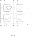
- FIGS. 3A to 3D show an operating process of a battery fire-extinguishing apparatus according to an embodiment operates.
- FIG. 3A shows the plurality of battery modules M1, M2, M3, M4, ..., the plurality of fire-extinguishing fluid storing units P1, P2, P3, P4, ... respectively located in the plurality of battery modules M1, M2, M3, M4, ..., and the plurality of resistor units R1, R2, R3, R4, ... respectively adjacent or attached to the plurality of fire-extinguishing fluid storing units.
- the resistor units R1, R2, R3, R4, ... may be connected in parallel on an equivalent circuit.
- the fire-extinguishing fluid storing unit P1 and the resistor unit R1 in the corresponding module M1 may be destroyed by heating and thus the fire-extinguishing fluid stored in the fire-extinguishing fluid storing unit P1 may be discharged, as shown in FIG. 3B , thereby extinguishing the fire and suppressing heat generation in the battery module M1.
- opening of the circuit caused by destruction of the resistor unit R1, may increase voltage applied to the other resistor units R2, R3, R4, ..., and current flowing through each resistor unit, and the heating pad included in the resistor units R2, R3, R4, ... may be rapidly heated.
- the fire-extinguishing fluid storing units P2, P3, P4, ..., respectively adjacent to or attached to the resistor units R2, R3, R4, ... may also be heated, and pouches burst at a certain temperature or more, thus discharging fire-extinguishing fluid.
- heat generation in the other battery modules M2, M3, M4, ..., than the battery module M1 where fire occurs may be suppressed and thermal explosion of the entire battery pack may be prevented.
- FIG. 4 is a flowchart showing an operating method of a battery fire-extinguishing apparatus according to an embodiment.
- the method according to an embodiment may be performed by the battery fire-extinguishing apparatus described above with reference to FIGS. 1 to 3 , but the present disclosure is not limited thereto and may be performed by a battery fire-extinguishing apparatus having other structures or forms.
- the battery pack may include the plurality of battery modules M1, M2, M3, M4, ..., the plurality of fire-extinguishing fluid storing units P1, P2, P3, P4, ... may be respectively located in the battery modules, and the plurality of resistor units R1, R2, R, R4, ... may be respectively adjacent to or attached to the fire-extinguishing fluid storing units.
- the plurality of resistor units may be electrically connected to one another in parallel, and each resistor unit may include a heating pad that is destroyed by heating to open the connected circuit.
- a fire-extinguishing fluid storing unit in the corresponding module bursts to discharge fire-extinguishing fluid and thus suppress heat generation, and at the same time, a heating pad of a resistor unit is destroyed to open a circuit and change voltage across all ends of resistors connected in parallel.
- FIG. 5 is a flowchart showing an operating method of a battery fire-extinguishing apparatus according to another embodiment.
- operation S510 voltage across both ends of a plurality of resistor units respectively adjacent to a plurality of fire-extinguishing fluid storing units respectively located in a plurality of battery modules may be monitored. Operation S510 is similar to operation S410 of FIG. 4 and thus will not be described in detail.
- operation S520 the voltage across both ends of the plurality of resistor units may be compared with the reference voltage. Operation S520 may be performed by the comparator 110 described with reference to FIG. 2 , and when some of the plurality of resistor units connected in parallel are destroyed to open the circuit, thus increasing voltage across all the ends of the plurality of resistor units.
- a switch circuit may be controlled to block electric connection between the plurality of resistor units and a serial resistor having the greater resistance value than the plurality of resistor units, thereby increasing current flowing through each of the plurality of resistor units.
- each of the plurality of resistor units may have a resistance value of several to several tens of ohms, and the serial resistor may have a resistance value of several hundreds of kilo-ohms.
- the serial resistor may have a resistance value of several hundreds of kilo-ohms.
- the voltage across both ends of the resistor unit may be higher than the reference voltage and the switch may be opened and closed by the output signal from the comparator (110 of FIG. 2 ) to disconnect the serial resistor from the resistor unit and increase the current flowing through each of the plurality of resistor units.
- the plurality of resistor units and adjacent fire-extinguishing fluid storing units adjacent thereto may be heated to discharge fire-extinguishing fluid from the fire-extinguishing fluid storing units. More specifically, as the serial resistor and the resistor unit are electrically disconnected, most of the voltage supplied from the power supply unit may be applied to the resistor unit, inducing increase of the current flowing through the resistor unit and heating of the heating pad. As a result, the fire-extinguishing fluid storing unit adjacent to the resistor unit or having attached thereto the resistor unit may burst due to heating to discharge the fire-extinguishing fluid and prevent heat spread to the battery module where fire does not occur.
- the operating method of the battery fire-extinguishing apparatus may be implemented in the form of an application or a program instruction that is executable through various computer components and recorded in a computer-readable recording medium.
- the computer-readable recording medium may include a program instruction, a data file, a data structure and the like solely or in a combined manner.
- fire-extinguishing fluid when fire occurs in some battery module of a battery pack, fire-extinguishing fluid may be discharged to suppress ignition, and fire-extinguishing fluid may be automatically discharged into all the other battery modules, thereby preventing heat spread to the other battery modules. Therefore, it is possible to prevent the battery pack from exploding due to an unexpected accident or result in a big fire.
Landscapes
- Emergency Management (AREA)
- Health & Medical Sciences (AREA)
- Business, Economics & Management (AREA)
- Public Health (AREA)
- Electrochemistry (AREA)
- General Chemical & Material Sciences (AREA)
- Chemical Kinetics & Catalysis (AREA)
- Chemical & Material Sciences (AREA)
- Physics & Mathematics (AREA)
- General Physics & Mathematics (AREA)
- Engineering & Computer Science (AREA)
- Manufacturing & Machinery (AREA)
- Battery Mounting, Suspending (AREA)
- Secondary Cells (AREA)
- Primary Cells (AREA)
Abstract
Description
- This application claims priority to and the benefit of
Korean Patent Application No. 10-2022-0103000 filed in the Korean Intellectual Property Office on August 17, 2022 - Embodiments disclosed herein relate to a battery fire-extinguishing apparatus and an operating method thereof.
- Recently, research and development of secondary batteries have been actively performed. Secondary batteries, which are chargeable/dischargeable batteries, may include all of conventional nickel (Ni)/cadmium (Cd) batteries, Ni/metal hydride (MH) batteries, etc., and recent lithium-ion batteries. Among them, a lithium-ion battery has a much higher energy density than those of conventional Ni/Cd batteries, Ni/MH batteries, etc. Moreover, the lithium-ion battery may be manufactured to be small and lightweight, such that the lithium-ion battery has been used as a power source of mobile devices, and recently, a use range thereof has been extended to power sources for electric vehicles, attracting attention as next-generation energy storage media.
- With the recently increasing utilization of large-capacity batteries such as electric vehicles, etc., battery safety issues have emerged. In particular, explosion of a battery module or occurrence of fire for some reasons may directly lead to a serious casualty accident, making it important not only to monitor the state of the battery in real time, but also to minimize damage by extinguishing ignition of the battery module early upon occurrence the ignition of the battery module. Nevertheless, an existing battery module not only has no countermeasures against abnormal ignition, but also has no technique for preventing thermal runaway by taking action in adjacent other battery modules when fire occurs in some battery module.
- Embodiments disclosed herein aim to provide a battery fire-extinguishing apparatus and an operating method thereof in which when fire occurs in some battery module of a battery pack, ignition may be suppressed using fire-extinguishing fluid and heat spread to other battery modules may be prevented.
- Technical problems of the embodiments disclosed herein are not limited to the above-described technical problems, and other unmentioned technical problems would be clearly understood by one of ordinary skill in the art from the following description.
- A battery fire-extinguishing apparatus includes a plurality of fire-extinguishing fluid storing units respectively located in a plurality of battery modules and configured to discharge fire-extinguishing fluid by heating, a plurality of resistor units respectively adjacent to the plurality of fire-extinguishing fluid storing units, and a control circuit configured to monitor voltage across both ends of the plurality of resistor units and increase current flowing through each of the plurality of resistor units when the voltage is higher than a reference voltage.
- In the battery fire-extinguishing apparatus according to an embodiment, the plurality of resistor units may be electrically connected to one another in parallel, and each resistor unit may include a heating pad that is destroyed by heating to open the connected circuit.
- In the battery fire-extinguishing apparatus according to an embodiment, the voltage across the both ends of the plurality of resistor units may be higher than the reference voltage when the heating pad included in at least one of the plurality of resistor units is destroyed.
- In the battery fire-extinguishing apparatus according to an embodiment, a fire-extinguishing fluid storing unit adjacent to each resistor unit may be configured to discharge fire-extinguishing fluid by heating, when the current flowing through each of the plurality of resistor units increases.
- In the battery fire-extinguishing apparatus according to an embodiment, the fire-extinguishing fluid may include a material that prevents an electrolyte gas in the battery module from contacting oxygen and lowers a temperature in the battery module.
- In the battery fire-extinguishing apparatus according to an embodiment, the control circuit may include a comparator configured to compare the voltage across both ends of the plurality of resistor units with the reference voltage, a serial resistor serially connected to the plurality of resistor units, a power supply unit configured to supply power to the plurality of resistor units and the circuit connected to the serial resistor, and at least one switch configured to electrically connect or disconnect the plurality of resistor units to or from the serial resistor, in which, when the voltage across the both ends of the plurality of resistor units is higher than the reference voltage, electric connection between the plurality of resistors and the serial resistor is blocked to increase the current flowing through each of the plurality of resistor units.
- In the battery fire-extinguishing apparatus according to an embodiment, the serial resistor may have a greater resistance value than a total resistance value of the plurality of resistor units.
- In the battery fire-extinguishing apparatus according to an embodiment, the control circuit may further include a regulator configured to maintain voltage supplied from the power supply unit at a certain level and supply the voltage to the comparator.
- An operating method of a battery fire-extinguishing apparatus includes monitoring voltage across both ends of a plurality of resistor units respectively adjacent to a plurality of fire-extinguishing fluid storing units respectively located in a plurality of battery modules and increasing current flowing through each of the plurality of resistor units when voltage is higher than a reference voltage.
- In the operating method of the battery fire-extinguishing apparatus according to an embodiment, the increasing of the current flowing through each of the plurality of resistor units may include comparing the voltage across both ends of the plurality of resistor units with the reference voltage and controlling a switch circuit to block electric connection between the plurality of resistor units and a serial resistor having a greater resistance value than the plurality of resistor units, when the voltage across the both ends of the plurality of resistor units is higher than the reference voltage.
- The operating method of the battery fire-extinguishing apparatus according to an embodiment may further include heating the plurality of resistor units and the fire-extinguishing fluid storing unit to discharge fire-extinguishing fluid from the fire-extinguishing fluid storing unit.
- According to the proposed battery fire-extinguishing apparatus, when fire occurs in some battery module of a battery pack, fire-extinguishing fluid may be automatically discharged to suppress fire ignition.
- Moreover, when fire occurs in some battery module, fire-extinguishing fluid may be automatically discharged into all other battery modules to prevent heat from spreading to the other battery modules.
- Moreover, various effects recognized directly or indirectly from the disclosure may be provided.
- In order to more clearly describe technical solutions of embodiments disclosed herein or the prior art, the drawings required in the description of the embodiments are briefly introduced below. It should be understood that the following drawings are for the purpose of explaining the embodiments of the present specification and not for limiting purposes. In addition, representations of some components in the drawings may be exaggerated or omitted for clarity of explanation.
-
FIG. 1 shows a structure of a battery module in which a battery fire-extinguishing apparatus according to an embodiment is installed. -
FIG. 2 shows an equivalent circuit structure of a battery fire-extinguishing apparatus according to an embodiment. -
FIGS. 3A to 3D show an operating process of a battery fire-extinguishing apparatus according to an embodiment operates. -
FIG. 4 is a flowchart showing an operating method of a battery fire-extinguishing apparatus according to an embodiment. -
FIG. 5 is a flowchart showing an operating method of a battery fire-extinguishing apparatus according to another embodiment. - Hereinafter, embodiments disclosed in this document will be described in detail with reference to the exemplary drawings. In adding reference numerals to components of each drawing, it should be noted that the same components are given the same reference numerals even though they are indicated in different drawings. In addition, in describing the embodiments disclosed in this document, when it is determined that a detailed description of a related known configuration or function interferes with the understanding of an embodiment disclosed in this document, the detailed description thereof may be omitted.
- Although terms used herein are selected with general terms popularly used at present under the consideration of functions in the disclosure, the terms may vary according to the intention of those of ordinary skill in the art, custom, or introduction of new technology. In addition, in a specific case, the applicant voluntarily may select terms, and in this case, the meaning of the terms may be disclosed in a corresponding description part of the present specification. Therefore, the terms used herein should be defined not by the simple names of the terms but by the substantial meaning of the terms and the contents throughout the disclosure.
- Moreover, terms defined in the present disclosure are used for only describing a specific exemplary embodiment and may not have an intention to limit the scope of other exemplary embodiments. It is to be understood that the singular forms include plural references unless the context clearly dictates otherwise. Herein, expressions such as "first" and "second" are used to distinguish components from each other, and do not mean a rank or order among components.
- Hereinbelow, preferred embodiments of a battery fire-extinguishing apparatus and an operating method thereof will be described with reference to the drawings.
-
FIG. 1 shows a structure of a battery module in which a battery fire-extinguishing apparatus according to an embodiment is installed. - A battery pack used as a power source for an electronic device such as an electric vehicle, etc., includes a plurality of battery modules, each of which may include one or more battery cells. A battery cell is a component that is repeatedly chargeable/dischargeable and is capable of generating a potential difference through an electrochemical reaction. A battery cell may include a positive electrode, a negative electrode, a separator, and an electrolyte, and when internal short circuit occurs due to the absence of the separator, introduction of foreign metal substances, internal deformation, damage to the separator, etc., or overheating occurs due to abnormality of a control system, fire may occur due to a battery cell. Fire occurring in some battery cells may be spread to fire of other battery cells or battery modules where the battery cells are located, and fire occurring in some battery module may be spread to fire of other battery modules and the entire battery pack.
- Referring to
FIG. 1 , a battery pack may include a plurality of battery modules M1, M2, M3, M4, ..., and a battery fire-extinguishing apparatus according to an embodiment may include a plurality of fire-extinguishing fluid storing units P1, P2, P3, P4, ..., respectively located in the plurality of battery modules M1, M2, M3, M4, ..., a plurality of resistor units R1, R2, R3, R4, ..., adjacent respectively to the plurality of fire-extinguishing fluid storing units P1, P2, P3, P4, ..., and acontrol circuit 10 for controlling current flowing through the plurality of resistor units R1, R2, R3, R4, .... - The fire-extinguishing fluid storing units P1, P2, P3, P4, ..., may be respectively located in battery modules M1, M2, M3, M4, .... According to an embodiment, each fire-extinguishing fluid storing unit may include a pouch that bursts when heated at a certain temperature or more, and the fire-extinguishing fluid discharged from the fire-extinguishing fluid storing unit may include a material for preventing an electrolyte gas in the battery module from contacting oxygen to lower a temperature in the battery module. Thus, if fire occurs in the battery module or the battery module is excessively heated, the fire-extinguishing fluid storing unit in the battery module may burst to discharge the fire-extinguishing fluid, thus suppressing fire ignition.
- The resistor units R1, R2, R3, R4, ..., may be respectively disposed adjacent to the fire-extinguishing fluid storing units P1, P2, P3, P4, ..., and may be preferably attached to the surface of the fire-extinguishing fluid storing unit (pouch). The resistor units R1, R2, R3, R4, ... may be electrically connected to one another in parallel and resistance heat may be generated depending on current flowing through the resistor units. Moreover, each resistor unit may include a heating pad that is destroyed when heated at a certain temperature or more, and opens a connected circuit when the heating pad is destroyed.
- Assuming that some (e.g., M1) of the battery modules M1, M2, M3, M4, ... is overheated at a certain temperature or more or fire occurs, the fire-extinguishing fluid storing unit P1 may burst to suppress fire ignition of the battery module M1 and at the same time other resistors R2, R3, R4, ... connected to the resistor R1 in parallel may be heated to burst adjacent fire-extinguishing fluid storing units P2, P3, P4, ..., thereby suppressing or preventing fire ignition of the other battery modules M2, M3, M4, ....
- The
control circuit 10 may monitor voltage across both ends of the plurality of resistor units R1, R2, R3, R4, ... and increase current flowing through each resistor unit when the voltage is higher than a reference voltage, thereby inducing destruction of the fire-extinguishing fluid storing unit adjacent to each resistor unit. A detailed operating method of thecontrol circuit 10 will be described later. - Hereinbelow, with reference to
FIGS. 2 and3A to 3D , an operating principle for suppressing fire ignition in other battery modules adjacent to a battery module where fire occurs will be described. -
FIG. 2 shows an equivalent circuit structure of a battery fire-extinguishing apparatus according to an embodiment. - Referring to
FIG. 2 , thecontrol circuit 10 of the battery fire-extinguishing apparatus may include acomparator 110 for comparing voltage at both ends of the resistor units R1, R2, R3, ..., Rn with a reference voltage Vref, at least one switches 121 and 122 for electrically connecting or disconnecting a resistor unit to or from a serial resistor, and apower supply unit 130 for supplying power to the circuit. - The
comparator 110 may compare a voltage Vr across both ends of the resistor units R1, R2, R3, ..., Rn with the reference voltage Vref and open or close theswitches - In a normal state where fire does not occur in the battery module or the battery module is not overheated, the plurality of resistor units R1, R2, R3, ..., Rn may be connected to one another in parallel and all ends of the resistor units may be serially connected to the serial resistor Rr. Herein, the serial resistor Rr may have a resistance value greater than a total resistance RTotal of the resistor units R1, R2, R3, ..., Rn. For example, each of the plurality of resistor units R1, R2, R3, ..., Rn may have a resistance value of several to several tens of ohms, and the serial resistor Rr may have a resistance value of several hundreds of kilo-ohms. Moreover, the serial resistor Rr is shown as a single resistor element in
FIG. 2 , but may also include a plurality of resistors connected in series. In such a normal state, a high voltage may be applied to a serial resistor having a great resistance value according to a voltage distribution principle, and a total resistance value RTotal+Rr of the circuit is very great, such that a small amount of current may flow through the resistor units R1, R2, R3, ..., Rn. - More specifically, referring to
FIG. 2 , when fire does not occur (i.e., any resistance of a resistor unit is not removed), the voltage Vr across both ends of the resistor unit may be less than the reference voltage Vref, and theswitch 121 may maintain an open state and theswitch 122 may maintain a closed state. Thus, the resistors R1, R2, R3, ..., Rn may be serially connected to the serial resistor Rr, and most of voltage supplied to thepower supply unit 130 may be applied to the serial resistor Rr. - Meanwhile, in an abnormal state where fire occurs in the battery module or the battery module is overheated at a certain temperature or more, for example, when fire occurs in an nth battery module among a plurality of battery modules, the fire-extinguishing fluid storing unit located in the battery module and the resistor unit Rn adjacent thereto may be destroyed by heating. At this time, as the fire-extinguishing fluid stored in the fire-extinguishing fluid storing unit is spread, heat generation in the module may be automatically suppressed, but when the fire-extinguishing fluid is not sufficient to completely suppress heat generation, heat generation may be spread to adjacent other modules, resulting in chain fire. According to a proposed embodiment, chain thermal runaway may be prevented using a method described below.
- When a heating pad included in the resistor unit Rn is destroyed due to fire in a specific battery module, a circuit of the corresponding portion is opened. Referring to
FIG. 2 , some Rn of the plurality of resistor units R1, R2, R3, ..., Rn connected in parallel may be removed to increase the total resistance RTotal of the ends of the resistor units, such that the voltage Vr across both ends of the resistor units may also increase (the principle of voltage distribution). - Also in this case, the voltage Vr at both ends of the resistor units is much lower than the voltage across both ends of the serial resistor Rr (due to a resistance value difference), but when the voltage Vr across the both ends of the resistor units is greater than the reference voltage Vref, the
switch 121 may switch to the closed state and theswitch 122 may switch to the open state according to a result of comparison of thecomparator 110. Due to an operation of the switch, the resistors R1, R2, R3, ..., and the serial resistor Rr may be electrically disconnected, and most of the voltage supplied by thepower supply unit 130 may be applied to the resistor units R1, R2, R3, .... - Thus, the voltage across the both ends of the resistor units R1, R2, R3, ... may greatly increase when compared to the normal state, and current flowing through each resistor unit may greatly increase. As current flowing through the resistor units increases, a heat generation amount of the heating pad of each resistor unit may also increase and an adjacent fire-extinguishing fluid storing unit (or having attached thereto the heating pad) may discharge the fire-extinguishing fluid at a certain temperature or more.
- In other words, when fire occurs in some battery module, this may lead to destruction of the resistor unit in the battery module and opening of the circuit, and due to switch control of the
comparator 110 that monitors voltage change over all ends of the resistor units, voltage and current amount applied to all the ends of the resistor units may largely increase. As a result, by increasing heat generation of the resistor (heating pad) in the battery module where fire does not occur, and inducing destruction of the fire-extinguishing fluid storing unit, thermal explosion of the entire battery pack may be suppressed. - According to an embodiment, the
control circuit 10 of the battery fire-extinguishing apparatus may further include aregulator 140 for maintaining voltage supplied from thepower supply unit 130 at a certain level to supply the voltage to thecomparator 110. -
FIGS. 3A to 3D show an operating process of a battery fire-extinguishing apparatus according to an embodiment operates. -
FIG. 3A shows the plurality of battery modules M1, M2, M3, M4, ..., the plurality of fire-extinguishing fluid storing units P1, P2, P3, P4, ... respectively located in the plurality of battery modules M1, M2, M3, M4, ..., and the plurality of resistor units R1, R2, R3, R4, ... respectively adjacent or attached to the plurality of fire-extinguishing fluid storing units. As described above, the resistor units R1, R2, R3, R4, ... may be connected in parallel on an equivalent circuit. - When fire occurs due to abnormality of a battery cell (e.g., internal shortcircuit, abnormality of a control system, etc.) in some battery module M1 as shown in
FIG. 3A , the fire-extinguishing fluid storing unit P1 and the resistor unit R1 in the corresponding module M1 may be destroyed by heating and thus the fire-extinguishing fluid stored in the fire-extinguishing fluid storing unit P1 may be discharged, as shown inFIG. 3B , thereby extinguishing the fire and suppressing heat generation in the battery module M1. - Moreover, as shown in
FIG. 3C , opening of the circuit, caused by destruction of the resistor unit R1, may increase voltage applied to the other resistor units R2, R3, R4, ..., and current flowing through each resistor unit, and the heating pad included in the resistor units R2, R3, R4, ... may be rapidly heated. - As a result, the fire-extinguishing fluid storing units P2, P3, P4, ..., respectively adjacent to or attached to the resistor units R2, R3, R4, ... may also be heated, and pouches burst at a certain temperature or more, thus discharging fire-extinguishing fluid. Thus, heat generation in the other battery modules M2, M3, M4, ..., than the battery module M1 where fire occurs may be suppressed and thermal explosion of the entire battery pack may be prevented.
-
FIG. 4 is a flowchart showing an operating method of a battery fire-extinguishing apparatus according to an embodiment. The method according to an embodiment may be performed by the battery fire-extinguishing apparatus described above with reference toFIGS. 1 to 3 , but the present disclosure is not limited thereto and may be performed by a battery fire-extinguishing apparatus having other structures or forms. - Referring to
FIG. 4 , in operation S410, voltage across both ends of a plurality of resistor units respectively adjacent to a plurality of fire-extinguishing fluid storing units respectively located in a plurality of battery modules may be monitored. - As described with reference to
FIG. 1 , the battery pack may include the plurality of battery modules M1, M2, M3, M4, ..., the plurality of fire-extinguishing fluid storing units P1, P2, P3, P4, ... may be respectively located in the battery modules, and the plurality of resistor units R1, R2, R, R4, ... may be respectively adjacent to or attached to the fire-extinguishing fluid storing units. - According to an embodiment, the plurality of resistor units may be electrically connected to one another in parallel, and each resistor unit may include a heating pad that is destroyed by heating to open the connected circuit. When fire occurs in some battery module, a fire-extinguishing fluid storing unit in the corresponding module bursts to discharge fire-extinguishing fluid and thus suppress heat generation, and at the same time, a heating pad of a resistor unit is destroyed to open a circuit and change voltage across all ends of resistors connected in parallel.
- In operation S420, when voltage across both ends of the plurality of resistor units (the other resistor units than the destroyed resistor unit) is higher than a reference voltage, current flowing through each of the plurality of resistor units may increase to heat the resistor unit, thus discharging fire-extinguishing fluid from a plurality of fire-extinguishing fluid storing units adjacent thereto. Thus, the fire-extinguishing fluid may suppress heat generation in the other battery modules than the battery module where fire occurs, and thermal explosion of the entire battery pack may be prevented.
-
FIG. 5 is a flowchart showing an operating method of a battery fire-extinguishing apparatus according to another embodiment. - Referring to
FIG. 5 , in operation S510, voltage across both ends of a plurality of resistor units respectively adjacent to a plurality of fire-extinguishing fluid storing units respectively located in a plurality of battery modules may be monitored. Operation S510 is similar to operation S410 ofFIG. 4 and thus will not be described in detail. - In operation S520, the voltage across both ends of the plurality of resistor units may be compared with the reference voltage. Operation S520 may be performed by the
comparator 110 described with reference toFIG. 2 , and when some of the plurality of resistor units connected in parallel are destroyed to open the circuit, thus increasing voltage across all the ends of the plurality of resistor units. - In operation S530, when the voltage across the both ends of the plurality of resistor units is higher than the reference voltage, a switch circuit may be controlled to block electric connection between the plurality of resistor units and a serial resistor having the greater resistance value than the plurality of resistor units, thereby increasing current flowing through each of the plurality of resistor units.
- According to an embodiment, each of the plurality of resistor units may have a resistance value of several to several tens of ohms, and the serial resistor may have a resistance value of several hundreds of kilo-ohms. Thus, in the normal state (that is, a state where fire does not occur in any battery module), most voltage may be applied to the serial resistor having the greater resistance value and a small amount of current may flow through the plurality of resistor units.
- On the other hand, in the abnormal state (a state where fire occurs in some battery module and thus some resistor unit is destroyed), the voltage across both ends of the resistor unit may be higher than the reference voltage and the switch may be opened and closed by the output signal from the comparator (110 of
FIG. 2 ) to disconnect the serial resistor from the resistor unit and increase the current flowing through each of the plurality of resistor units. - In operation S540, the plurality of resistor units and adjacent fire-extinguishing fluid storing units adjacent thereto may be heated to discharge fire-extinguishing fluid from the fire-extinguishing fluid storing units. More specifically, as the serial resistor and the resistor unit are electrically disconnected, most of the voltage supplied from the power supply unit may be applied to the resistor unit, inducing increase of the current flowing through the resistor unit and heating of the heating pad. As a result, the fire-extinguishing fluid storing unit adjacent to the resistor unit or having attached thereto the resistor unit may burst due to heating to discharge the fire-extinguishing fluid and prevent heat spread to the battery module where fire does not occur.
- The operating method of the battery fire-extinguishing apparatus according to the embodiment may be implemented in the form of an application or a program instruction that is executable through various computer components and recorded in a computer-readable recording medium. The computer-readable recording medium may include a program instruction, a data file, a data structure and the like solely or in a combined manner.
- According to the foregoing embodiments, when fire occurs in some battery module of a battery pack, fire-extinguishing fluid may be discharged to suppress ignition, and fire-extinguishing fluid may be automatically discharged into all the other battery modules, thereby preventing heat spread to the other battery modules. Therefore, it is possible to prevent the battery pack from exploding due to an unexpected accident or result in a big fire.
- So far, all components constituting the embodiment have been described as being combined or operating in combination, but it is not necessarily limited to this embodiment, and within the scope of the purpose, all components may be selectively combined with one or more to operate. Moreover, terms such as "include", "constitute", "have", etc., described above may mean that the corresponding component may be inherent unless otherwise stated, and thus should be construed as further including other components rather than excluding other components.
- The above description is merely illustrative of the technical idea of the present disclosure, and various modifications and variations will be possible without departing from the essential characteristics of embodiments of the present disclosure by those of ordinary skill in the art to which the embodiments disclosed herein pertains.
- Therefore, the embodiments disclosed herein are intended for description rather than limitation of the technical spirit of the embodiments disclosed herein and the scope of the technical spirit of the present disclosure is not limited by these embodiments disclosed herein. The protection scope of the technical spirit disclosed herein should be interpreted by the following claims, and all technical spirits within the same range should be understood to be included in the range of the present disclosure.
Claims (11)
- A battery fire-extinguishing apparatus comprising:a plurality of fire-extinguishing fluid storing units respectively located in a plurality of battery modules and configured to discharge fire-extinguishing fluid by heating;a plurality of resistor units respectively adjacent to the plurality of fire-extinguishing fluid storing units; anda control circuit configured to monitor voltage across both ends of the plurality of resistor units and increase current flowing through each of the plurality of resistor units when the voltage is higher than a reference voltage.
- The battery fire-extinguishing apparatus of claim 1, wherein the plurality of resistor units are electrically connected to one another in parallel, and each resistor unit comprises a heating pad that is destroyed by heating to open the connected circuit.
- The battery fire-extinguishing apparatus of claim 2, wherein the voltage across the both ends of the plurality of resistor units is higher than the reference voltage when the heating pad included in at least one of the plurality of resistor units is destroyed.
- The battery fire-extinguishing apparatus of claim 3, wherein a fire-extinguishing fluid storing unit adjacent to each resistor unit is configured to discharge fire-extinguishing fluid by heating, when the current flowing through each of the plurality of resistor units increases.
- The battery fire-extinguishing apparatus of claim 4, wherein the fire-extinguishing fluid comprises a material that prevents an electrolyte gas in the battery module from contacting oxygen and lowers a temperature in the battery module.
- The battery fire-extinguishing apparatus of claim 1, wherein the control circuit comprises:a comparator configured to compare the voltage across both ends of the plurality of resistor units with the reference voltage;a serial resistor serially connected to the plurality of resistor units;a power supply unit configured to supply power to the plurality of resistor units and the circuit connected to the serial resistor; andat least one switch configured to electrically connect or disconnect the plurality of resistor units to or from the serial resistor,wherein, when the voltage across the both ends of the plurality of resistor units is higher than the reference voltage, electric connection between the plurality of resistors and the serial resistor is blocked to increase the current flowing through each of the plurality of resistor units.
- The battery fire-extinguishing apparatus of claim 6, wherein the serial resistor has a greater resistance value than a total resistance value of the plurality of resistor units.
- The battery fire-extinguishing apparatus of claim 6, wherein the control circuit further comprises a regulator configured to maintain voltage supplied from the power supply unit at a certain level and supply the voltage to the comparator.
- An operating method of a battery fire-extinguishing apparatus, the operating method comprising:monitoring voltage across both ends of a plurality of resistor units respectively adjacent to a plurality of fire-extinguishing fluid storing units respectively located in a plurality of battery modules; andincreasing current flowing through each of the plurality of resistor units when voltage is higher than a reference voltage.
- The operating method of claim 9, wherein the increasing of the current flowing through each of the plurality of resistor units comprises:comparing the voltage across both ends of the plurality of resistor units with the reference voltage; andcontrolling a switch circuit to block electric connection between the plurality of resistor units and a serial resistor having a greater resistance value than the plurality of resistor units, when the voltage across the both ends of the plurality of resistor units is higher than the reference voltage.
- The operating method of claim 10, further comprising heating the plurality of resistor units and the fire-extinguishing fluid storing unit to discharge fire-extinguishing fluid from the fire-extinguishing fluid storing unit.
Applications Claiming Priority (2)
| Application Number | Priority Date | Filing Date | Title |
|---|---|---|---|
| KR1020220103000A KR20240024695A (en) | 2022-08-17 | 2022-08-17 | Battery fire extinguishing device and operating method thereof |
| PCT/KR2023/012188 WO2024039198A1 (en) | 2022-08-17 | 2023-08-17 | Battery fire extinguishing device and operating method thereof |
Publications (3)
| Publication Number | Publication Date |
|---|---|
| EP4553976A1 true EP4553976A1 (en) | 2025-05-14 |
| EP4553976A4 EP4553976A4 (en) | 2025-09-10 |
| EP4553976B1 EP4553976B1 (en) | 2026-05-20 |
Family
ID=89942012
Family Applications (1)
| Application Number | Title | Priority Date | Filing Date |
|---|---|---|---|
| EP23855164.2A Active EP4553976B1 (en) | 2022-08-17 | 2023-08-17 | BATTERY FIRE EXTINGUISHER AND OPERATING PROCEDURES |
Country Status (6)
| Country | Link |
|---|---|
| US (1) | US20260041946A1 (en) |
| EP (1) | EP4553976B1 (en) |
| JP (1) | JP2025528809A (en) |
| KR (1) | KR20240024695A (en) |
| CN (1) | CN119678301A (en) |
| WO (1) | WO2024039198A1 (en) |
Family Cites Families (9)
| Publication number | Priority date | Publication date | Assignee | Title |
|---|---|---|---|---|
| US20130264073A1 (en) * | 2012-04-10 | 2013-10-10 | Greg Ling | Integrated Thermal Event Suppression Apparatus |
| JP2016002419A (en) * | 2014-06-19 | 2016-01-12 | Necエンジニアリング株式会社 | Fire-extinguishing system and fire-extinguishing method for power storage device |
| JP2016092007A (en) * | 2014-10-29 | 2016-05-23 | 日本ドライケミカル株式会社 | Thermal runaway suppression system of secondary battery |
| KR102250161B1 (en) * | 2017-06-16 | 2021-05-07 | 주식회사 엘지화학 | Battery module with improved safety and Battery pack comprising the |
| KR102766496B1 (en) * | 2019-08-09 | 2025-02-10 | 주식회사 엘지에너지솔루션 | A battery pack with an energy drain resistor for prevention of chain ignition |
| KR102901907B1 (en) * | 2020-05-13 | 2025-12-19 | 주식회사 엘지에너지솔루션 | Battery pack containing fire suppression means |
| KR20220090635A (en) * | 2020-12-22 | 2022-06-30 | 주식회사 더센 | Battery safety system for a battery pack or module comprising one or more secondary battery cells |
| KR102260561B1 (en) | 2021-01-14 | 2021-06-04 | 주식회사 이엘엠 | Composition For Capping Layer of Organic Light Emitting Diode and Organic Light Emitting Diode Having The Same |
| KR102297771B1 (en) * | 2021-03-29 | 2021-09-02 | 한국전지연구조합 | Used battery module storage system |
-
2022
- 2022-08-17 KR KR1020220103000A patent/KR20240024695A/en active Pending
-
2023
- 2023-08-17 WO PCT/KR2023/012188 patent/WO2024039198A1/en not_active Ceased
- 2023-08-17 US US19/101,574 patent/US20260041946A1/en active Pending
- 2023-08-17 EP EP23855164.2A patent/EP4553976B1/en active Active
- 2023-08-17 CN CN202380059161.5A patent/CN119678301A/en active Pending
- 2023-08-17 JP JP2025507659A patent/JP2025528809A/en active Pending
Also Published As
| Publication number | Publication date |
|---|---|
| EP4553976B1 (en) | 2026-05-20 |
| US20260041946A1 (en) | 2026-02-12 |
| KR20240024695A (en) | 2024-02-26 |
| CN119678301A (en) | 2025-03-21 |
| EP4553976A4 (en) | 2025-09-10 |
| WO2024039198A1 (en) | 2024-02-22 |
| JP2025528809A (en) | 2025-09-02 |
Similar Documents
| Publication | Publication Date | Title |
|---|---|---|
| KR100485752B1 (en) | Secondary Battery Protection Device | |
| US11626626B2 (en) | Lithium-ion battery impending failure detection | |
| US9413031B2 (en) | Apparatus and system for an internal fuse in a battery cell | |
| CN114930607B (en) | Battery pack including fire suppression device | |
| KR102203248B1 (en) | Battery module and battery pack including the same | |
| US6046514A (en) | Bypass apparatus and method for series connected energy storage devices | |
| JP3367382B2 (en) | Lithium ion secondary battery | |
| US20240313290A1 (en) | Safety control mechanism and method, battery system, and electrical apparatus | |
| US20240356110A1 (en) | Safety regulation mechanism and method, battery system and electrical apparatus | |
| WO2021118893A1 (en) | Method and system for thermal management of a battery system | |
| KR102063937B1 (en) | Apparatus and method for managing battery pack | |
| US20260041946A1 (en) | Battery fire-extinguishing apparatus and operating method thereof | |
| US12334599B2 (en) | Battery module and energy storage device | |
| EP3965198B1 (en) | Online measurement of anode potential for the maximization of charging power at low temperatures | |
| KR20220064097A (en) | Battery device capable of controlling rapid change of temperature by using phase change materials and method for operation of battery device using same | |
| US20250239679A1 (en) | Battery system with improved cooling circuit | |
| RU2846540C2 (en) | Protective regulation mechanism and method, battery system and electric device | |
| EP4531180A1 (en) | Battery system with improved thermal runaway handling | |
| RU2847091C2 (en) | Protective control mechanism and method, battery system and electric device | |
| EP4199211B1 (en) | Battery cell and battery system | |
| JP7408214B2 (en) | Overcurrent application prevention device and method | |
| US20250239741A1 (en) | Battery module and energy storage system including the same | |
| CN119907755A (en) | Ignition combustion of rechargeable lithium batteries in unmanned electronic devices | |
| KR20250176143A (en) | Battery System and Electric Vehicle Comprising the Battery System | |
| HK40129833A (en) | Sensors for battery protection |
Legal Events
| Date | Code | Title | Description |
|---|---|---|---|
| STAA | Information on the status of an ep patent application or granted ep patent |
Free format text: STATUS: THE INTERNATIONAL PUBLICATION HAS BEEN MADE |
|
| PUAI | Public reference made under article 153(3) epc to a published international application that has entered the european phase |
Free format text: ORIGINAL CODE: 0009012 |
|
| STAA | Information on the status of an ep patent application or granted ep patent |
Free format text: STATUS: REQUEST FOR EXAMINATION WAS MADE |
|
| 17P | Request for examination filed |
Effective date: 20250204 |
|
| AK | Designated contracting states |
Kind code of ref document: A1 Designated state(s): AL AT BE BG CH CY CZ DE DK EE ES FI FR GB GR HR HU IE IS IT LI LT LU LV MC ME MK MT NL NO PL PT RO RS SE SI SK SM TR |
|
| A4 | Supplementary search report drawn up and despatched |
Effective date: 20250811 |
|
| RIC1 | Information provided on ipc code assigned before grant |
Ipc: H01M 50/24 20210101AFI20250805BHEP Ipc: A62C 3/16 20060101ALI20250805BHEP Ipc: A62C 35/10 20060101ALI20250805BHEP Ipc: A62C 37/10 20060101ALI20250805BHEP Ipc: H02H 3/20 20060101ALI20250805BHEP Ipc: G01R 19/165 20060101ALI20250805BHEP Ipc: H01M 10/42 20060101ALI20250805BHEP Ipc: H01M 50/569 20210101ALI20250805BHEP |
|
| DAV | Request for validation of the european patent (deleted) | ||
| DAX | Request for extension of the european patent (deleted) | ||
| REG | Reference to a national code |
Ref legal event code: R079 Ipc: A62C0003160000 Ref country code: DE Ref legal event code: R079 Ref document number: 602023017598 Country of ref document: DE Free format text: PREVIOUS MAIN CLASS: H01M0050240000 Ipc: A62C0003160000 |
|
| GRAP | Despatch of communication of intention to grant a patent |
Free format text: ORIGINAL CODE: EPIDOSNIGR1 |
|
| STAA | Information on the status of an ep patent application or granted ep patent |
Free format text: STATUS: GRANT OF PATENT IS INTENDED |
|
| RIC1 | Information provided on ipc code assigned before grant |
Ipc: A62C 3/16 20060101AFI20260109BHEP Ipc: G01R 19/165 20060101ALI20260109BHEP Ipc: H01M 50/682 20210101ALI20260109BHEP Ipc: H01M 10/48 20060101ALN20260109BHEP |
|
| INTG | Intention to grant announced |
Effective date: 20260123 |
|
| GRAS | Grant fee paid |
Free format text: ORIGINAL CODE: EPIDOSNIGR3 |
|
| GRAA | (expected) grant |
Free format text: ORIGINAL CODE: 0009210 |
|
| STAA | Information on the status of an ep patent application or granted ep patent |
Free format text: STATUS: THE PATENT HAS BEEN GRANTED |
|
| P01 | Opt-out of the competence of the unified patent court (upc) registered |
Free format text: CASE NUMBER: UPC_APP_0011027_4553976/2026 Effective date: 20260326 |