EP4553956A1 - Battery and battery pack - Google Patents
Battery and battery pack Download PDFInfo
- Publication number
- EP4553956A1 EP4553956A1 EP24192149.3A EP24192149A EP4553956A1 EP 4553956 A1 EP4553956 A1 EP 4553956A1 EP 24192149 A EP24192149 A EP 24192149A EP 4553956 A1 EP4553956 A1 EP 4553956A1
- Authority
- EP
- European Patent Office
- Prior art keywords
- plate
- battery
- electrode assembly
- cavity
- vapor chamber
- Prior art date
- Legal status (The legal status is an assumption and is not a legal conclusion. Google has not performed a legal analysis and makes no representation as to the accuracy of the status listed.)
- Pending
Links
Images





Classifications
-
- H—ELECTRICITY
- H01—ELECTRIC ELEMENTS
- H01M—PROCESSES OR MEANS, e.g. BATTERIES, FOR THE DIRECT CONVERSION OF CHEMICAL ENERGY INTO ELECTRICAL ENERGY
- H01M10/00—Secondary cells; Manufacture thereof
- H01M10/60—Heating or cooling; Temperature control
- H01M10/61—Types of temperature control
- H01M10/617—Types of temperature control for achieving uniformity or desired distribution of temperature
-
- H—ELECTRICITY
- H01—ELECTRIC ELEMENTS
- H01M—PROCESSES OR MEANS, e.g. BATTERIES, FOR THE DIRECT CONVERSION OF CHEMICAL ENERGY INTO ELECTRICAL ENERGY
- H01M10/00—Secondary cells; Manufacture thereof
- H01M10/60—Heating or cooling; Temperature control
- H01M10/61—Types of temperature control
- H01M10/613—Cooling or keeping cold
-
- H—ELECTRICITY
- H01—ELECTRIC ELEMENTS
- H01M—PROCESSES OR MEANS, e.g. BATTERIES, FOR THE DIRECT CONVERSION OF CHEMICAL ENERGY INTO ELECTRICAL ENERGY
- H01M10/00—Secondary cells; Manufacture thereof
- H01M10/60—Heating or cooling; Temperature control
- H01M10/64—Heating or cooling; Temperature control characterised by the shape of the cells
- H01M10/647—Prismatic or flat cells, e.g. pouch cells
-
- H—ELECTRICITY
- H01—ELECTRIC ELEMENTS
- H01M—PROCESSES OR MEANS, e.g. BATTERIES, FOR THE DIRECT CONVERSION OF CHEMICAL ENERGY INTO ELECTRICAL ENERGY
- H01M10/00—Secondary cells; Manufacture thereof
- H01M10/60—Heating or cooling; Temperature control
- H01M10/65—Means for temperature control structurally associated with the cells
- H01M10/654—Means for temperature control structurally associated with the cells located inside the innermost case of the cells, e.g. mandrels, electrodes or electrolytes
-
- H—ELECTRICITY
- H01—ELECTRIC ELEMENTS
- H01M—PROCESSES OR MEANS, e.g. BATTERIES, FOR THE DIRECT CONVERSION OF CHEMICAL ENERGY INTO ELECTRICAL ENERGY
- H01M10/00—Secondary cells; Manufacture thereof
- H01M10/60—Heating or cooling; Temperature control
- H01M10/65—Means for temperature control structurally associated with the cells
- H01M10/655—Solid structures for heat exchange or heat conduction
- H01M10/6552—Closed pipes transferring heat by thermal conductivity or phase transition, e.g. heat pipes
-
- H—ELECTRICITY
- H01—ELECTRIC ELEMENTS
- H01M—PROCESSES OR MEANS, e.g. BATTERIES, FOR THE DIRECT CONVERSION OF CHEMICAL ENERGY INTO ELECTRICAL ENERGY
- H01M10/00—Secondary cells; Manufacture thereof
- H01M10/60—Heating or cooling; Temperature control
- H01M10/65—Means for temperature control structurally associated with the cells
- H01M10/655—Solid structures for heat exchange or heat conduction
- H01M10/6554—Rods or plates
-
- H—ELECTRICITY
- H01—ELECTRIC ELEMENTS
- H01M—PROCESSES OR MEANS, e.g. BATTERIES, FOR THE DIRECT CONVERSION OF CHEMICAL ENERGY INTO ELECTRICAL ENERGY
- H01M10/00—Secondary cells; Manufacture thereof
- H01M10/60—Heating or cooling; Temperature control
- H01M10/65—Means for temperature control structurally associated with the cells
- H01M10/655—Solid structures for heat exchange or heat conduction
- H01M10/6556—Solid parts with flow channel passages or pipes for heat exchange
-
- H—ELECTRICITY
- H01—ELECTRIC ELEMENTS
- H01M—PROCESSES OR MEANS, e.g. BATTERIES, FOR THE DIRECT CONVERSION OF CHEMICAL ENERGY INTO ELECTRICAL ENERGY
- H01M10/00—Secondary cells; Manufacture thereof
- H01M10/60—Heating or cooling; Temperature control
- H01M10/65—Means for temperature control structurally associated with the cells
- H01M10/655—Solid structures for heat exchange or heat conduction
- H01M10/6556—Solid parts with flow channel passages or pipes for heat exchange
- H01M10/6557—Solid parts with flow channel passages or pipes for heat exchange arranged between the cells
-
- H—ELECTRICITY
- H01—ELECTRIC ELEMENTS
- H01M—PROCESSES OR MEANS, e.g. BATTERIES, FOR THE DIRECT CONVERSION OF CHEMICAL ENERGY INTO ELECTRICAL ENERGY
- H01M10/00—Secondary cells; Manufacture thereof
- H01M10/60—Heating or cooling; Temperature control
- H01M10/65—Means for temperature control structurally associated with the cells
- H01M10/656—Means for temperature control structurally associated with the cells characterised by the type of heat-exchange fluid
- H01M10/6567—Liquids
- H01M10/6568—Liquids characterised by flow circuits, e.g. loops, located externally to the cells or cell casings
-
- H—ELECTRICITY
- H01—ELECTRIC ELEMENTS
- H01M—PROCESSES OR MEANS, e.g. BATTERIES, FOR THE DIRECT CONVERSION OF CHEMICAL ENERGY INTO ELECTRICAL ENERGY
- H01M10/00—Secondary cells; Manufacture thereof
- H01M10/60—Heating or cooling; Temperature control
- H01M10/65—Means for temperature control structurally associated with the cells
- H01M10/656—Means for temperature control structurally associated with the cells characterised by the type of heat-exchange fluid
- H01M10/6569—Fluids undergoing a liquid-gas phase change or transition, e.g. evaporation or condensation
-
- H—ELECTRICITY
- H01—ELECTRIC ELEMENTS
- H01M—PROCESSES OR MEANS, e.g. BATTERIES, FOR THE DIRECT CONVERSION OF CHEMICAL ENERGY INTO ELECTRICAL ENERGY
- H01M50/00—Constructional details or processes of manufacture of the non-active parts of electrochemical cells other than fuel cells, e.g. hybrid cells
- H01M50/10—Primary casings; Jackets or wrappings
- H01M50/102—Primary casings; Jackets or wrappings characterised by their shape or physical structure
- H01M50/103—Primary casings; Jackets or wrappings characterised by their shape or physical structure prismatic or rectangular
-
- H—ELECTRICITY
- H01—ELECTRIC ELEMENTS
- H01M—PROCESSES OR MEANS, e.g. BATTERIES, FOR THE DIRECT CONVERSION OF CHEMICAL ENERGY INTO ELECTRICAL ENERGY
- H01M50/00—Constructional details or processes of manufacture of the non-active parts of electrochemical cells other than fuel cells, e.g. hybrid cells
- H01M50/70—Arrangements for stirring or circulating the electrolyte
-
- Y—GENERAL TAGGING OF NEW TECHNOLOGICAL DEVELOPMENTS; GENERAL TAGGING OF CROSS-SECTIONAL TECHNOLOGIES SPANNING OVER SEVERAL SECTIONS OF THE IPC; TECHNICAL SUBJECTS COVERED BY FORMER USPC CROSS-REFERENCE ART COLLECTIONS [XRACs] AND DIGESTS
- Y02—TECHNOLOGIES OR APPLICATIONS FOR MITIGATION OR ADAPTATION AGAINST CLIMATE CHANGE
- Y02E—REDUCTION OF GREENHOUSE GAS [GHG] EMISSIONS, RELATED TO ENERGY GENERATION, TRANSMISSION OR DISTRIBUTION
- Y02E60/00—Enabling technologies; Technologies with a potential or indirect contribution to GHG emissions mitigation
- Y02E60/10—Energy storage using batteries
Definitions
- the present disclosure relates to the battery field, in particular to a battery and a battery pack.
- the battery pack includes a battery case and a cell module.
- the cell module is composed of a plurality of cells.
- the cell module converts electric energy into chemical energy when charging, and converts chemical energy into electric energy when discharging. Since the cell module will generate a large amount of heat during the charging and discharging process, and in order to ensure the safety of the battery pack, a cooling plate is generally arranged on the bottom of the battery pack, that is, below the cell module, to reduce the overall temperature of the battery pack.
- the cooling plate is only arranged below the battery module, when the heat on the top of the battery cell cannot be dissipated in time, the temperature difference between the position away from the bottom of the battery cell and the bottom of the battery cell is large, which is not conducive to battery circulation and affects the service life of the battery pack.
- the embodiments of the present disclosure provide a battery and a battery pack to solve the above technical problems.
- the embodiments of the present disclosure provide a battery including a housing, an electrode assembly, and a vapor chamber.
- the housing is provided with an accommodating cavity.
- the electrode assembly is disposed in the accommodating cavity.
- the vapor chamber includes a first side plate part and a first bottom plate part connected in sequence.
- the first side plate part is attached to a side wall of the electrode assembly.
- the first bottom plate part is disposed between a bottom of the electrode assembly and the housing.
- a plurality of first through holes are defined by the first side plate part.
- the embodiments of the present disclosure provide a battery pack including the above-mentioned battery.
- the battery and the battery pack provided by the embodiments of the present disclosure include a battery housing, an electrode assembly and a vapor chamber.
- the electrode assembly is disposed in the accommodation cavity of the battery housing.
- the vapor chamber includes a first side plate part and a first bottom plate part connected in sequence.
- the first side plate part is attached to the side wall of the electrode assembly.
- the first bottom plate part is disposed between the bottom of the electrode assembly and the housing.
- the first side plate part is used for transferring heat far away from the bottom of the electrode assembly to the bottom of the electrode assembly. Thereby, the heat can be dissipated through the cooling plate outside the housing, thereby reducing the temperature difference between other positions of the electrode assembly and the top of the electrode assembly, and prolonging the service life of the battery cell.
- the present disclosure provides a battery 10a including a battery housing 100, an electrode assembly 200, and a vapor chamber 300a.
- the battery housing 100 includes an accommodating cavity, and the electrode assembly 200 is disposed in the accommodating cavity.
- the vapor chamber 300a includes a first side plate part 301 and a first bottom plate part 302 connected in sequence.
- the first side plate part 301 is attached to a side wall of the electrode assembly 200.
- the first bottom plate part 302 is provided between a bottom of the electrode assembly 200 and the battery housing 100.
- the first side plate part 301 is provided with a plurality of first through holes 303.
- the first side plate part 301 is used to transfer heat away from the bottom of the electrode assembly 200 to the bottom of the electrode assembly 200, thereby enabling the heat to be dissipated through the cooling plate 20 outside the battery housing 100, thereby reducing the temperature difference between other positions of the electrode assembly 200 and the top of the electrode assembly 200, and prolonging the service life of the battery 10a.
- the first side plate part 301a is provided with the plurality of the first through holes 303, so that the electrolyte in the accommodating cavity can normally flow to the side wall of the electrode assembly 200, and the charging and discharging power of the battery 10a can be prevented from decreasing due to the provision of the vapor chamber 300a.
- first side plate part 301 and the first bottom plate part 302 may be integrally formed, such as an integrally formed structure formed by die-casting, injection molding, or the like, or may be a split structure connected by screws, welding, or the like.
- An end of the first side plate part 301 is connected to one side of the first bottom plate part 302. Or an end of the first side plate part 301 is connected to a central part of the first bottom plate part 302.
- the vapor chamber 300a is made of metal or some materials with better heat conduction effect.
- the material of the vapor chamber 300a also has high corrosion resistance and chemical stability.
- At least a part of the first through holes 303 of the first side plate part 301 are capable of extending to an edge of the first side plate part 301, forming a groove-shaped structure provided in the first side plate part 301 to increase the flow through the first side plate part 301.
- the interior of the vapor chamber 300a is a hollow structure with a heat conduction cavity isolated from the outside, and a liquid medium is stored in the heat conduction cavity for heat conduction.
- the first side plate part 301 extends from the top of the electrode assembly 200 to the bottom of the electrode assembly 200. That is, a length of the first side plate part 301 is equal to a height of the electrode assembly 200, thereby ensuring that heat from the top of the electrode assembly 200 is transferred to the first bottom plate part 302 of the bottom plate of the electrode assembly 200 through the vapor chamber 300a provided on the side wall of the electrode assembly 200, thereby reducing the temperature difference between the top and bottom of the electrode assembly 200.
- the first side plate part 301 may also extend from the bottom of the electrode assembly 200 to the middle of the electrode assembly 200, that is, the first side plate part 301 covers only a part of the electrode assembly 200, so as to reduce the production cost of the battery 10a.
- the first side plate part 301 completely covers at least one side wall of the electrode assembly 200.
- the first side plate part 301 completely covers at least one side wall of the electrode assembly 200, so that the heat of the electrode assembly 200 in the horizontal direction can be uniform, thereby reducing the temperature difference at various parts of the electrode assembly 200 in the horizontal direction.
- the electrode assembly 200 is of a cuboid structure, and the first side plate part 301 is completely attached to at least one side wall surface of the cuboid electrode assembly 200, or the first side plate part 301 completely covers the side wall surface of the cuboid structure.
- the electrode assembly 200 may also be of a cylinder structure, and the first side plate part 301 may completely wrap and cover the entire side wall of the cylinder structure, or may only cover the side wall within a certain radian range.
- the first bottom plate part 302 completely coincides with the bottom of the electrode assembly 200. That is, the shape and size of the first bottom plate part 302 are identical to the shape and size of the bottom of the electrode assembly 200.
- the size of the first base plate part 302 is much larger than the size of the bottom of the electrode assembly 200, and in condition of the electrode assembly 200 being disposed on the first base plate part 302, the first base plate part 302 may completely cover the bottom of the electrode assembly 200.
- a plurality of electrode assemblies 200 may be carried on one bottom plate part.
- the first bottom plate part 302 may be provided with a plurality of second through holes for flowing the electrolyte.
- the first through holes 303 of the first side plate part 301 are arranged in an array.
- the above-mentioned array arrangement may be a rectangular array arrangement or a ring array arrangement, and is not limited here.
- the main purpose is to uniformly distribute a plurality of the first through holes 303 in the first side plate part 301, so as to ensure that the side walls of the electrode assembly 200 attached to the first side plate part 301 can uniformly contact the electrolyte.
- the vapor chamber 300a further includes a first top plate part 304 attached to the top of the electrode assembly 200 and connected to the first side plate part 301, and located between the top of the battery housing 100 and the top of the electrode assembly 200.
- connection mode between the first top plate 304 and the first side plate 301 may be referred to the connection mode between the first bottom plate 302 and the first side plate 301.
- the first top plate 304 and the first bottom plate 302 are connected to both ends of the first side plate 301, respectively.
- the end of the first side plate 301 is connected to one side of the first top plate 304, or the end of the first side plate part 301 is connected to the middle of the first top plate part 304.
- first top plate part 304 and the electrode assembly 200 are arranged in the same manner as the first bottom plate part 302. That is, one first top plate 304 may correspond to one electrode assembly 200, or one first top plate 304 may correspond to a plurality of the electrode assemblies 200. That is, one first top plate part 304 may cover the top of one electrode assembly 200, or one first top plate part 304 may cover the tops of the plurality of the electrode assemblies 200.
- the top of the electrode assembly 200 is completely covered.
- the first top plate part 304 is also provided with a plurality of third through holes for flowing the electrolyte.
- the electrode assembly 200 includes a first core 201 and a second core 202 adjacent to each other.
- the first side plate part 301 is connected to the first bottom plate part 302 to an inverted T-shaped structure.
- the first side plate part 301 is located between the first electrode assembly 201 and the second electrode assembly 202. Both sides of the first side plate part 301 are attached to the side wall of the first electrode assembly 201 and the side wall of the second electrode assembly 202, respectively.
- the bottom of the first electrode assembly 201 and the bottom of the second electrode assembly 202 are both provided on the first bottom plate part 302.
- the vapor chamber 300a has an H-shaped structure with clockwise or counterclockwise rotation of 90 degrees.
- the vapor chamber 300a includes a first top plate part 304, a first bottom plate part 302, and a first side plate part 301.
- the first top plate part 304 and the first side plate part 301 are vertically connected and parallel to the first bottom plate part 302.
- the battery housing 100 includes a lower housing 101 and a top cover assembly.
- the top cover assembly covers the lower housing 101.
- the top cover assembly fits with the lower housing 101 to form the accommodating cavity.
- the top cover assembly includes a cover plate 102 and a connecting sheet 103, the cover plate 102 covers the lower housing 101 and cooperates with the lower housing 101 to form an accommodating cavity, the electrode assembly 200 and the vapor chamber 300a are both provided in the accommodating cavity.
- the connecting sheet 103 is disposed in the accommodating cavity for electrically connecting the cover plate 102 and the electrode assembly 200.
- the present disclosure further provides a battery pack including the battery 10a of the above embodiments. Since the battery pack includes the battery 10a in the above embodiments, the battery pack has at least some or all of the beneficial effects of the battery 10a in the above embodiments, and will not be described in detail here.
- the battery pack includes a battery case, a battery module, and a cooling plate 20.
- the battery module is composed of a plurality of batteries 10a arranged in an array, and the battery module is arranged in the battery case.
- the cooling plate 20 is disposed between the bottom of the battery module and the bottom of the battery case, and is used for cooling the battery module.
- the transfer rate of the gaseous working medium in the bending area decreases, which affects the thermal conductivity of the vapor chamber.
- the present disclosure further provides a vapor chamber, which is an L-shaped vapor chamber.
- a vapor chamber which is an L-shaped vapor chamber.
- the vapor chamber 300b provided by the embodiments of the present disclosure includes the L-shaped housing 310 and the one-way valve 320 for transferring the gaseous working medium.
- the L-shaped housing 310 includes a first cover plate 311 and a second cover plate.
- the fist cover plate 311 includes a first transverse plate 3111 and a first vertical plate 3112 connected to the first transverse plate 3111 to form an L-shaped shape pattern.
- the second cover plate 312 includes a second transverse plate 3121 and a second vertical plate 3122 connected to the second transverse plate 3121 to form an L-shaped shape pattern. That is, both the first cover plate 311 and the second cover plate 312 are L-shaped pattern.
- first transverse plates 3111 and the structure of the second transverse plates 3121 may refer to the structure of the first bottom plate part 302 in the above embodiments
- structure of the first vertical plates 3112 and the structure of the second vertical plates 3122 may refer to the structure of the first side plate part 301 in the above embodiments.
- the L-shaped housing 310 may be made of copper, copper alloy, aluminum, aluminum alloy, stainless steel, other metals, other metal alloys, or the like, that is, the L-shaped housing 310 may be made of one of the above-mentioned materials.
- the stainless steel may be SUS304, SUS314, or the like.
- an outer surface of the L-shaped housing 310 may be subjected to insulation spraying or electroplating treatment, for example, when the stainless steel is used to manufacture the L-shaped housing 310, the stainless steel outer surface may be copper plated, or the like.
- An edge of the first transverse plate 3111 is sealed and connected to the second transverse plate 3121 to form a condensation part of the L-shaped housing.
- An edge of the first vertical plate 3112 is sealed and connected to an edge of the second vertical plate 3122 to form an evaporation part of the L-shaped housing.
- the edges of the plurality of the transverse plates and the connecting edges of the plurality of the vertical plates do not include edges at the junction of the transverse plates and the vertical plates, for example, the edge of the first transverse plate 3111 is an edge other than an edge connected to the first vertical plate 3112, that is, the edge of the first transverse plate 3111 does not include the edge at the junction of the first transverse plate 3111 and the first vertical plate 3112.
- the first cover plate 311 may serve as a support plate for the vapor chamber 300b.
- the second cover plate 312 may serve as a cover plate for covering the support plate. That is, from the perspective of the condensation part of the L-shaped housing 310, the first cover plate 311 is located below the condensation part and the second cover plate 312 is located above condensation part.
- the second cover plate 312 may serve as the support plate for the vapor chamber 300b
- the first cover plate 311 may serve as a cover plate for the vapor chamber 300b. That is, the first cover plate 311 is located above the condensation part and the second cover plate 312 is located below the condensation part.
- a first cavity is provided between the first transverse plate 3111 and the second transverse plate 3121.
- a second cavity is provided between the first vertical plate 3112 and the second vertical plate 3122.
- the first cavity and the second cavity communicate to form an L-shaped sealed cavity 313.
- the sealed cavity 313 is a vacuum chamber, and a liquid working medium, such as pure water or ethanol, is injected into the sealed cavity 313.
- the one-way valve 320 is located in the sealed cavity 313 and is provided on the first cover plate 311.
- An inlet end of the one-way valve 320 is provided on an inner wall of the first vertical plate 3112.
- An outlet end of the one-way valve 320 extends along the first vertical plate 3112 and through the connection of the first vertical plate 3112 and the first transverse plate 3111 to an inner wall of the first transverse plate 3111.
- an extending direction of the one-way valve 320 on the first vertical plate 3112 is a direction of a height H of the first vertical plate 3112.
- an extending direction of the one-way valve 320 on the first transverse plate 3111 is a direction of a width W of the first transverse plate 3111.
- the connection of the first vertical plate 3112 and the first transverse plate 3111 may be understood as a bending area of the L-shaped housing 310, that is, the one-way valve 320 of the present disclosure is provided in the bending area of the L-shaped housing 310, so that when the evaporation part of the L-shaped housing 310 is heated and the liquid working medium is evaporated into a gaseous working medium (i.e., heat), the gaseous working medium is capable of being transferred to the condensation part of the L-shaped housing 310 at the bending area through the one-way valve 320.
- the gas flow in the bending area can be accelerated by the directional transmission effect of the one-way valve, thereby increasing the heat conduction rate and improving the thermal conductivity of the vapor chamber 300b.
- the one-way valve 320 by providing the one-way valve 320, the transmission of the gaseous working medium against gravity direction can be avoided, thereby reducing the transmission air resistance, and the gas flow rate can be increased by more than 5 times compared with
- the one-way valve 320 in the embodiments of the present disclosure may be a Tesla one-way valve.
- a length of the one-way valve 320 extending on the first vertical plate 3112 is three-quarter of a height H of the first vertical plate 3112
- a length of the one-way valve 320 extending on the first transverse plate 3111 is three-quarter of a width W of the first transverse plate 3111. More specifically, the inlet end of the one-way valve 320 approaches an end of the first vertical plate 3112 away from the first horizontal plate 3111.
- the outlet end of the one-way valve 320 approaches an end of the first horizontal plate 3111 away from the first vertical plate 3112, so that the gaseous working medium can enter the one-way valve 320 more quickly to be transmitted to the condensation part through the one-way valve 320, and the transmission of the gaseous working medium can be further accelerated.
- the length of the one-way valve 320 extending on the first transverse plate 3111 or the first vertical plate 3112 may be one-half or one-quarter of the first transverse plate 3111 or the first vertical plate 3112, or may be provided according to actual needs.
- the vapor chamber 300b of the embodiments of the present disclosure further includes N wicks 330, N ⁇ 2, located in the sealed cavity 313, and the N wicks 330 extend from the evaporation part to the condensation part.
- the wick 330 may be provided on the first cover plate 311 or the second cover plate 312, or the wick 330 may be provided on both the first cover plate 311 and the second cover plate 312, without specific limitation.
- the N wicks 330 are arranged on the first cover plate 311, one end of the wick 330 is located on the inner wall of the first vertical plate 3112, and the other end of the wick 330 extends along the first vertical plate 3112 and through the connection of the first vertical plate 3112 and the first transverse plate 3111 to the inner wall of the first transverse plate 311.
- one end of the wick 330 is flush with one end of the first vertical plate 3112 away from the first transverse plate 3111, and the other end of the wick 330 is flush with one end of the first transverse plate 3111 away from the first vertical plate 3112. That is, the wick 330 covers the first cover plate 311 in the longitudinal direction thereof (referring to the wick 330), thereby facilitating the transmission and diffusion of liquid working medium.
- the N wicks 330 are arranged sequentially in the direction of the length L of the L-shaped housing 310. As shown in FIG. 6 , the length of the L-shaped housing 310 is also the length L of the first vertical plate 3112 and the length L second vertical plate 3122.
- the i-th wick 330 is arranged at (2*i-1)/2N of the length L of the L-shaped housing 310, for example, when i is equal to 1, the first wick is located at 1/2 N of the length L of the first vertical plate 3112. For example, when N is equal to 2, the two wicks 330 are arranged at 1/4 and 3/4 of the length L of the first vertical plate 3112, respectively.
- the positions of the five wicks 330 on the first vertical plate 3112 are 1/10, 3/10, 1/2, 7/10, and 9/10 of the length L of the first vertical plate 3112, respectively.
- the number of the wicks of the vapor chamber may be greater than or equal to 2.
- the positions of the three wicks 330 on the first vertical plate 3112 are 1/6, 1/2, and 5/6 of the length L of the first vertical plate 3112, respectively.
- the arrangement position of the wicks may be uniformly arranged or the like.
- each wick 330 ranges from 1.9 mm to 2.3 mm.
- the width may be 2.0 mm
- the thickness is 0.2 mm
- the single wire diameter ranges from 0.05 mm to 0.1 mm.
- the single wire diameter value is defined as the outer diameter of the wick, for example, may be 0.1 mm
- the mesh number is 200 mesh
- the surface of the wick 330 has a copper oxide layer, and the contact angle between the capillary structure of the wick 300 and the surface of the copper oxide layer is 0 degree, so that the hydrophilicity of the wick 330 can be improved.
- a core e.g.
- a copper mesh is first made of T2 pure copper material, then the surface of the core is oxidized to form a copper oxide layer, and a capillary structure is formed on the surface of the copper oxide, and the contact angle between the capillary structure and the surface of the copper oxide is 0 degree, so that the wick 330 has a super hydrophilic property. If the capillary structure is directly formed on the surface of the pure copper core without oxidizing treatment, the contact angle between the capillary structure and the surface of the pure copper core is large, generally ranging from 80 to 88 degrees, and the hydrophilic property is poor.
- the surface tension of the capillary structure of the wick 330 is 0.08 N/m, so that the anti-gravity climbing ability of the wick 330 can be improved, and the working fluid in the the cold area can quickly climb, thereby accelerating the circulation of the liquid working medium.
- a plurality of one-way valves 320 may be provided, and the one-way valves 320 and the wicks 330 may be alternately arranged.
- the one-way valves 320 may be provided between two adjacent wicks 330.
- one side of the one-way valve 320 away from the first cover 311 abuts the second cover 312. That is, a part of the one-way valve 320 located on the first vertical plate 3112 abuts the second vertical plate 3122, and a part of the one-way valve 320 located on the first transverse plate 3111 abuts the second transverse plate 3121 to form a support for the sealed cavity 313, thereby greatly improving the deformation resistance of the vapor chamber 300b.
- a plurality of support columns 340 and a plurality of support strips 350 for supporting the sealed cavity 313 are provided in the sealed cavity 313.
- a plurality of the support columns 340 may be distributed in the first cavity or in the second cavity, or support columns 340 may be provided in both the first cavity and the second cavity, and the support columns 340 may be abutted between the first cover plate 311 and the second cover plate 312. More specifically, one end of the support columns 340 may be fixed on the first cover plate 311 and the other end may be abutted with the second cover plate 312, or one end of the support columns 340 may be fixed on the second cover plate 312 and the other end may be abutted with the first cover plate 311.
- Each support strip 350 extends from the evaporation part to the condensation part.
- the support strip 350 may be provided on the first cover plate 311 or on the second cover plate 312, or the support strip 350 may be provided on both the first cover plate 311 and the second cover plate 312.
- the support strip 350 is disposed on the first cover plate 311, one end of the support strip 350 is disposed on the inner wall of the first vertical plate 3112, and the other end of the support strip 350 extends along the inner wall of the first vertical plate 3112 and through the connection of the first vertical plate 3112 and the first transverse plate 3111 to the inner wall of the first transverse plate 3111.
- the side of the support strip 350 away from the first cover plate 311 abuts the second cover plate 121.
- the deformation resistance of the vapor chamber 300b can be further improved by the action of the support columns 340 and the support strips 350.
- a plurality of support strips 350 are arranged in the direction of the length L of the L-shaped housing 310.
- a distance between adjacent two support strips is 2 mm, and the width of the support strips is 0.4 mm.
- a total volume ratio of all the support strips 350 ranges from 4% to 8%. For example, may be 4%, 6% or 8%. In the total volume ratio range, the support strips 350 can effectively play a supporting role while making the sealed cavity 313 have sufficient space, so that the liquid working medium can be effectively transmitted. In addition, if the volume ratio is too small, the support ability of the support strip may be insufficient.
- the outer surface of the L-shaped housing 310 is deformed due to excessive pressure, which may cause the vapor chamber to contact the electrode assembly and cause damage to the electrode assembly. Therefore, by providing the total volume ratio in the above range in the present disclosure, it can not only provide sufficient support, but also prevent the support strip from occupying too much space of the sealed cavity 313.
- the vapor chamber 300b further includes a silk screen 360 located in the sealed cavity 313.
- the silk screen 360 may be provided on the evaporation part, for example, on the inner wall of the second vertical plate 3122 of the second cover plate 312.
- the silk screen 360 may be in contact with the wick 330, so that the liquid working medium transported by the wick 330 against gravity can be quickly diffused to the entire surface of the evaporation part.
- Each node of the silk screen 360 corresponds to a boiling core capable of accelerating the boiling of the liquid working medium in the area, thereby accelerating the transition of the liquid working medium from the liquid state to the gaseous state.
- the silk screen 360 may extend from the evaporation part to the condensation part.
- the silk screen 360 may be provided on the inner wall of the second transverse plate 3121 and inner wall of the second vertical plate 3122 of the second cover plate 312. That is, the silk screen 360 extends from the second vertical plate 3122 to the second transverse plate 3121, the liquid working medium of the condensation part may also be transmitted to the evaporation part through the silk screen 360, and the wick 330, and the silk screen 360 together transmit the liquid working medium.
- the silk screen 360 may be in contact with the wick 330, which may collect the dispersed liquid working medium, and the collected liquid working medium may be transmitted to the evaporation part along the silk screen 360 and the wick 330, improving the transmission efficiency.
- Each node of the silk screen 360 located in the evaporation section is equivalent to a boiling core, which can accelerate the boiling of the liquid working medium in this area, thereby accelerating the transformation of the liquid working medium from the liquid state to the gaseous state.
- the silk screen 360 of the present disclosure the liquid working medium can be collected and transmitted, and the boiling of the liquid working medium at the evaporation section can be accelerated.
- the screen 360 may be provided on the first cover plate.
- a thickness of the silk screen 360 ranges from 0.1 mm to 0.17 mm.
- the mesh size is 250 mesh.
- the embodiments of the present disclosure further provides a battery 10b including at least one electrode assembly 200 and at least one vapor chamber.
- the vapor chamber is the vapor chamber 300b described in any of the above embodiments.
- the battery 10b further includes a battery housing 100.
- the electrode assembly 200 is disposed in the battery housing 100.
- the vapor chamber 300b is disposed in the battery housing 100.
- the electrode assembly 200 includes a top surface 2021 for setting poles, a bottom surface opposite the top surface 2021, and a side surface 2022 located between the top surface 2021 and the bottom surface.
- the condensation part of the L-shaped housing 310 of each vapor chamber 300b is attached to the bottom surface of one of the electrode assemblies 200.
- the second transverse plate 3121 of the second cover plate 312 is attached to the bottom surface of the electrode assemblies 200.
- the evaporation part of each L-shaped housing 310 is attached to a side surface 2022 of one of the electrode assemblies 200.
- the second vertical plate 3122 of the second cover 312 is attached to the side surface 2022 of the electrode assembly 200.
- the evaporation part of the L-shaped housing 310 is attached to the side surface of the largest area of the electrode assembly 200, that is, the second vertical plate 3122 is attached to the side surface of the largest area of the electrode assembly 200.
- the battery 10b further includes a cooling plate 80 which is attached to the bottom of the electrode assembly 200. It can be understood that the bottom of the electrode assemblies 200 is the part where the bottom surface of the electrode assemblies 200 is located.
- the cooling plate 80 and the electrode assembly 200 may be fixed by a thermally conductive glue.
- the L-shaped vapor chamber 300b is provided in the electrode assembly 200, and the heat generated by the pole can be quickly transferred to the bottom of the electrode assembly 200, so that the heat is transmitted to the cooling plate 80 in time and dissipated by the cooling plate 80, thereby improving the heat dissipation effect of the electrode assembly 200.
- the number of both the electrode assemblies 200 and the vapor chambers 300b is a plurality.
- the number of both the electrode assemblies 200 and the vapor chambers 300b is two.
- the battery 10b further includes a connecting sheet 103 and a cover plate 102.
- the connecting sheet 103 is used for connecting the electrode assembly 200.
- the pole is provided on the cover plate 102 for covering the battery housing 100.
- the evaporation parts of the L-shaped housings 310 of every two vapor chambers 300b are attached together, and the condensation parts extend in the opposite direction.
- the evaporation part of the vapor chamber 300b of the present disclosure is in contact with the large surface of the electrode assembly 200.
- the liquid working medium in the sealed cavity 313 thereof is located in the condensation part.
- the liquid working medium can climb against gravity along the wick 330, and diffuse to the entire evaporation part through the silk screen 360.
- a large amount of heat is generated at the pole of the electrode assembly 200, and the temperature is high, so that the liquid working medium of the evaporation part absorbs a large amount of heat and then gasifies into a gaseous working medium.
- the gaseous working medium moves along the cavity part in the sealed cavity 313 to the condensation part, and when passing through the bending area, the gaseous working medium can be transferred through the one-way valve 320.
- the gaseous working medium liquefies and releases heat, and the heat is carried away by the cooling plate 20 at the bottom of the electrode assembly 200.
- the liquefied working medium is re-collected at the condensation part, climbs and diffuses against gravity along the wick 330, absorbs heat and gasifies, and then moves downwards to liquefy when cold, realizing heat transfer in a cyclic manner.
- the transmission rate of the gaseous working medium in the bending area can be accelerated, so that the gaseous working medium can be directed and quickly moved to the bottom of the vapor chamber 300b, that is, the condensation part, thereby improving the heat transfer efficiency of the vapor chamber 300b and ensuring its thermal conductivity in the operating state of a large single cell battery.
- the support structure in the shape of a valve body strip is formed by the one-way valve 320, and the deformation resistance of the vapor chamber 300b can be greatly improved.
- the vapor chambers 300b and the batteries 10b are described above.
- the vapor chamber 300b includes a L-shaped housing 310 and a one-way valve 320 for transferring heat.
- the L-shaped housing 310 includes a first cover plate 311 and a second cover plate 312.
- the first cover plate 311 includes a first transverse plate 3111 and a first vertical plate 3112 connected to the first transverse plate 3111 to form an L-shaped shape pattern.
- the second cover plate 312 includes a second transverse plate 3121 and a second vertical plate 3122 connected to the second transverse plate 3121 to form an L-shaped shape pattern.
- the edges of the first transverse plate 3111 and the second transverse plate 3121 are sealed and connected to form a condensation part of the L-shaped housing 310.
- the edges of the first vertical plate 3112 and the second vertical plate 3122 are sealed and connected to form an evaporation part of the L-shaped housing.
- a first cavity is provided between the first transverse plate and the second transverse plate.
- a second cavity is provided between the first vertical plate and the second vertical plate. The first cavity is communicated with the second cavity to form the L-shaped sealed cavity 313.
- the one-way valve 320 is located in the sealed cavity 313 and is arranged on the first cover plate.
- the inlet end of the one-way valve 320 is arranged on the inner wall of the first vertical plate.
- the outlet end of the one-way valve 320 extends along the first vertical plate and through the connection of the first vertical plate and the first transverse plate to the inner wall of the first transverse plate.
- connection position of the first vertical plate and the first transverse plate is also the bending area of the L-shaped housing 310. That is, in the present disclosure, the one-way valve 320 is arranged in the bending area of the L-shaped housing 310 to transmit a gaseous working medium. The directional action of the one-way valve 320 can accelerate the gas flow in the bending area, thereby improving the thermal conductivity of the vapor chamber.
Landscapes
- Chemical & Material Sciences (AREA)
- Chemical Kinetics & Catalysis (AREA)
- Electrochemistry (AREA)
- General Chemical & Material Sciences (AREA)
- Engineering & Computer Science (AREA)
- Manufacturing & Machinery (AREA)
- Secondary Cells (AREA)
- Battery Mounting, Suspending (AREA)
Abstract
Description
- The present disclosure relates to the battery field, in particular to a battery and a battery pack.
- As the energy supply method of new energy electric vehicles, power batteries can achieve zero exhaust emissions and reduce environmental pollution compared with traditional fuel vehicles. The battery pack includes a battery case and a cell module. The cell module is composed of a plurality of cells. The cell module converts electric energy into chemical energy when charging, and converts chemical energy into electric energy when discharging. Since the cell module will generate a large amount of heat during the charging and discharging process, and in order to ensure the safety of the battery pack, a cooling plate is generally arranged on the bottom of the battery pack, that is, below the cell module, to reduce the overall temperature of the battery pack.
- However, since the cooling plate is only arranged below the battery module, when the heat on the top of the battery cell cannot be dissipated in time, the temperature difference between the position away from the bottom of the battery cell and the bottom of the battery cell is large, which is not conducive to battery circulation and affects the service life of the battery pack.
- The embodiments of the present disclosure provide a battery and a battery pack to solve the above technical problems.
- In a first aspect, the embodiments of the present disclosure provide a battery including a housing, an electrode assembly, and a vapor chamber. The housing is provided with an accommodating cavity. The electrode assembly is disposed in the accommodating cavity. The vapor chamber includes a first side plate part and a first bottom plate part connected in sequence. The first side plate part is attached to a side wall of the electrode assembly. The first bottom plate part is disposed between a bottom of the electrode assembly and the housing. A plurality of first through holes are defined by the first side plate part.
- In a second aspect, the embodiments of the present disclosure provide a battery pack including the above-mentioned battery.
- Beneficial effect: The battery and the battery pack provided by the embodiments of the present disclosure include a battery housing, an electrode assembly and a vapor chamber. The electrode assembly is disposed in the accommodation cavity of the battery housing. The vapor chamber includes a first side plate part and a first bottom plate part connected in sequence. The first side plate part is attached to the side wall of the electrode assembly. The first bottom plate part is disposed between the bottom of the electrode assembly and the housing. The first side plate part is used for transferring heat far away from the bottom of the electrode assembly to the bottom of the electrode assembly. Thereby, the heat can be dissipated through the cooling plate outside the housing, thereby reducing the temperature difference between other positions of the electrode assembly and the top of the electrode assembly, and prolonging the service life of the battery cell.
-
-
FIG. 1 is a schematic view of an internal structure of a battery provided by some embodiments of the present disclosure. -
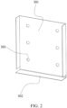
FIG. 2 is a first schematic view of a vapor chamber provided by some embodiments of the present disclosure. -
FIG. 3 is a second schematic view of the vapor chamber provided by some embodiments of the present disclosure. -
FIG. 4 is a first explosion schematic view of a battery provided by some embodiments of the present disclosure. -
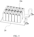
FIG. 5 is a schematic view of a battery module and a cooling plate provided by some embodiments of the present disclosure. -
FIG. 6 is a third schematic view of the vapor chamber provided by some embodiments of the present disclosure. -
FIG. 7 is a schematic view of a one-way valve being attached to a first cover plate of the vapor chamber provided in some embodiments of the present disclosure. -
FIG. 8 is a schematic view of a silk screen being attached to a second vertical plate provided in some embodiments of the present disclosure. -
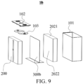
FIG. 9 is a second explosion schematic view of the battery provided by some embodiments of the present disclosure. -
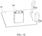
FIG. 10 is a schematic view of the battery module provided by some embodiments of the present disclosure. -
- 10a, battery; 20, cooling plate; 100, battery housing; 101, lower housing; 102, cover plate; 103, connecting sheet; 200, electrode assembly; 201, first electrode assembly; 202, second electrode assembly; 300a, vapor chamber; 301, first side plate part; 302, first bottom plate part; 303, first through hole; 304, first top plate part;
- 300b, vapor chamber; 310, L-shaped housing; 311, first cover plate; 3111, first transverse plate; 3112, first vertical plate; 312, second cover plate; 3121, second transverse plate; 3122, second vertical plate; 313, sealed cavity; 320, one-way valve; 330, wick; 340, support column; 350, support strip; 360, silk screen; 10b, battery; 2021, top surface; 2022, side surface.
- As shown in
FIGs. 1 to 5 , the present disclosure provides abattery 10a including abattery housing 100, anelectrode assembly 200, and avapor chamber 300a. Thebattery housing 100 includes an accommodating cavity, and theelectrode assembly 200 is disposed in the accommodating cavity. Thevapor chamber 300a includes a firstside plate part 301 and a firstbottom plate part 302 connected in sequence. The firstside plate part 301 is attached to a side wall of theelectrode assembly 200. The firstbottom plate part 302 is provided between a bottom of theelectrode assembly 200 and thebattery housing 100. The firstside plate part 301 is provided with a plurality of first throughholes 303. - It can be understood that the first
side plate part 301 is used to transfer heat away from the bottom of theelectrode assembly 200 to the bottom of theelectrode assembly 200, thereby enabling the heat to be dissipated through thecooling plate 20 outside thebattery housing 100, thereby reducing the temperature difference between other positions of theelectrode assembly 200 and the top of theelectrode assembly 200, and prolonging the service life of thebattery 10a. In addition, the first side plate part 301a is provided with the plurality of the first throughholes 303, so that the electrolyte in the accommodating cavity can normally flow to the side wall of theelectrode assembly 200, and the charging and discharging power of thebattery 10a can be prevented from decreasing due to the provision of thevapor chamber 300a. - It should be noted that the first
side plate part 301 and the firstbottom plate part 302 may be integrally formed, such as an integrally formed structure formed by die-casting, injection molding, or the like, or may be a split structure connected by screws, welding, or the like. - An end of the first
side plate part 301 is connected to one side of the firstbottom plate part 302. Or an end of the firstside plate part 301 is connected to a central part of the firstbottom plate part 302. - For better heat conduction, the
vapor chamber 300a is made of metal or some materials with better heat conduction effect. In order to adapt to the electrolyte environment in the accommodating cavity, the material of thevapor chamber 300a also has high corrosion resistance and chemical stability. - Optionally, in order to allow the electrolyte in the accommodating cavity to flow normally without interfering with the normal operation of the
battery 10a, at least a part of the first throughholes 303 of the firstside plate part 301 are capable of extending to an edge of the firstside plate part 301, forming a groove-shaped structure provided in the firstside plate part 301 to increase the flow through the firstside plate part 301. - In some embodiments, the interior of the
vapor chamber 300a is a hollow structure with a heat conduction cavity isolated from the outside, and a liquid medium is stored in the heat conduction cavity for heat conduction. - In some embodiments, the first
side plate part 301 extends from the top of theelectrode assembly 200 to the bottom of theelectrode assembly 200. That is, a length of the firstside plate part 301 is equal to a height of theelectrode assembly 200, thereby ensuring that heat from the top of theelectrode assembly 200 is transferred to the firstbottom plate part 302 of the bottom plate of theelectrode assembly 200 through thevapor chamber 300a provided on the side wall of theelectrode assembly 200, thereby reducing the temperature difference between the top and bottom of theelectrode assembly 200. - Of course, in some embodiments, the first
side plate part 301 may also extend from the bottom of theelectrode assembly 200 to the middle of theelectrode assembly 200, that is, the firstside plate part 301 covers only a part of theelectrode assembly 200, so as to reduce the production cost of thebattery 10a. - In some embodiments, the first
side plate part 301 completely covers at least one side wall of theelectrode assembly 200. - It can be understood that the larger the contact area between the first
side plate part 301 and theelectrode assembly 200, the better the heat dissipation effect thereof will be. The firstside plate part 301 completely covers at least one side wall of theelectrode assembly 200, so that the heat of theelectrode assembly 200 in the horizontal direction can be uniform, thereby reducing the temperature difference at various parts of theelectrode assembly 200 in the horizontal direction. - In some embodiments, the
electrode assembly 200 is of a cuboid structure, and the firstside plate part 301 is completely attached to at least one side wall surface of thecuboid electrode assembly 200, or the firstside plate part 301 completely covers the side wall surface of the cuboid structure. - In some embodiments, the
electrode assembly 200 may also be of a cylinder structure, and the firstside plate part 301 may completely wrap and cover the entire side wall of the cylinder structure, or may only cover the side wall within a certain radian range. - In some embodiments, the first
bottom plate part 302 completely coincides with the bottom of theelectrode assembly 200. That is, the shape and size of the firstbottom plate part 302 are identical to the shape and size of the bottom of theelectrode assembly 200. Alternatively, the size of the firstbase plate part 302 is much larger than the size of the bottom of theelectrode assembly 200, and in condition of theelectrode assembly 200 being disposed on the firstbase plate part 302, the firstbase plate part 302 may completely cover the bottom of theelectrode assembly 200. For example, a plurality ofelectrode assemblies 200 may be carried on one bottom plate part. - Similarly, in some embodiments, in order to improve the flowability of the electrolyte at the bottom of the
electrode assembly 200, the firstbottom plate part 302 may be provided with a plurality of second through holes for flowing the electrolyte. - In some embodiments, the first through
holes 303 of the firstside plate part 301 are arranged in an array. - The above-mentioned array arrangement may be a rectangular array arrangement or a ring array arrangement, and is not limited here. The main purpose is to uniformly distribute a plurality of the first through
holes 303 in the firstside plate part 301, so as to ensure that the side walls of theelectrode assembly 200 attached to the firstside plate part 301 can uniformly contact the electrolyte. - In some embodiments, the first through
hole 303 may be a circular through hole, a square through hole, or the like. - In some embodiments, the
vapor chamber 300a further includes a firsttop plate part 304 attached to the top of theelectrode assembly 200 and connected to the firstside plate part 301, and located between the top of thebattery housing 100 and the top of theelectrode assembly 200. - It can be understood that the connection mode between the first
top plate 304 and thefirst side plate 301 may be referred to the connection mode between thefirst bottom plate 302 and thefirst side plate 301. The firsttop plate 304 and thefirst bottom plate 302 are connected to both ends of thefirst side plate 301, respectively. The end of thefirst side plate 301 is connected to one side of the firsttop plate 304, or the end of the firstside plate part 301 is connected to the middle of the firsttop plate part 304. - Similarly, the first
top plate part 304 and theelectrode assembly 200 are arranged in the same manner as the firstbottom plate part 302. That is, one firsttop plate 304 may correspond to oneelectrode assembly 200, or one firsttop plate 304 may correspond to a plurality of theelectrode assemblies 200. That is, one firsttop plate part 304 may cover the top of oneelectrode assembly 200, or one firsttop plate part 304 may cover the tops of the plurality of theelectrode assemblies 200. - When the first
top plate part 304 is attached to the top of theelectrode assembly 200, the top of theelectrode assembly 200 is completely covered. - In some embodiments, the first
top plate part 304 is also provided with a plurality of third through holes for flowing the electrolyte. - In some embodiments, the
electrode assembly 200 includes afirst core 201 and asecond core 202 adjacent to each other. The firstside plate part 301 is connected to the firstbottom plate part 302 to an inverted T-shaped structure. The firstside plate part 301 is located between thefirst electrode assembly 201 and thesecond electrode assembly 202. Both sides of the firstside plate part 301 are attached to the side wall of thefirst electrode assembly 201 and the side wall of thesecond electrode assembly 202, respectively. The bottom of thefirst electrode assembly 201 and the bottom of thesecond electrode assembly 202 are both provided on the firstbottom plate part 302. - That is, in the embodiments, the
vapor chamber 300a has an inverted T-shaped structure. Two sides of one firstside plate part 301 are attached to twoadjacent electrode assemblies 200, respectively. The end of the firstside plate part 301 is connected to the middle of the firstbottom plate part 302, so that the firstbottom plate part 302 is divided into two parts, and the two parts correspond to the bottom of thefirst electrode assemblies 201 and the bottom of thesecond electrode assemblies 202 respectively. - In some embodiments, the
vapor chamber 300a has a L-shaped structure, that is, the firstbottom plate part 302 and the firstside plate part 301 are vertically connected and provided on the side and the bottom of theelectrode assembly 200, respectively. - In some embodiments, the
vapor chamber 300a has an H-shaped structure with clockwise or counterclockwise rotation of 90 degrees. In other words, thevapor chamber 300a includes a firsttop plate part 304, a firstbottom plate part 302, and a firstside plate part 301. The firsttop plate part 304 and the firstside plate part 301 are vertically connected and parallel to the firstbottom plate part 302. - In some embodiments, the
battery housing 100 includes alower housing 101 and a top cover assembly. The top cover assembly covers thelower housing 101. The top cover assembly fits with thelower housing 101 to form the accommodating cavity. - Specifically, the top cover assembly includes a
cover plate 102 and a connectingsheet 103, thecover plate 102 covers thelower housing 101 and cooperates with thelower housing 101 to form an accommodating cavity, theelectrode assembly 200 and thevapor chamber 300a are both provided in the accommodating cavity. The connectingsheet 103 is disposed in the accommodating cavity for electrically connecting thecover plate 102 and theelectrode assembly 200. - In some embodiments, the present disclosure further provides a battery pack including the
battery 10a of the above embodiments. Since the battery pack includes thebattery 10a in the above embodiments, the battery pack has at least some or all of the beneficial effects of thebattery 10a in the above embodiments, and will not be described in detail here. - In some embodiments, the battery pack includes a battery case, a battery module, and a
cooling plate 20. The battery module is composed of a plurality ofbatteries 10a arranged in an array, and the battery module is arranged in the battery case. The coolingplate 20 is disposed between the bottom of the battery module and the bottom of the battery case, and is used for cooling the battery module. - Due to the L-shaped vapor chamber having a bending angle, the transfer rate of the gaseous working medium in the bending area decreases, which affects the thermal conductivity of the vapor chamber.
- Based on the above deficiencies, the present disclosure further provides a vapor chamber, which is an L-shaped vapor chamber. By arranging a one-way valve in the bending area of the L-shaped vapor chamber, the guiding effect of the one-way valve can accelerate the gas flow in the bending area, thereby improving the thermal conductivity of the vapor chamber.
- Referring to
FIGs. 6 and7 , thevapor chamber 300b provided by the embodiments of the present disclosure includes the L-shapedhousing 310 and the one-way valve 320 for transferring the gaseous working medium. The L-shapedhousing 310 includes afirst cover plate 311 and a second cover plate. Thefist cover plate 311 includes a firsttransverse plate 3111 and a firstvertical plate 3112 connected to the firsttransverse plate 3111 to form an L-shaped shape pattern. Thesecond cover plate 312 includes a secondtransverse plate 3121 and a secondvertical plate 3122 connected to the secondtransverse plate 3121 to form an L-shaped shape pattern. That is, both thefirst cover plate 311 and thesecond cover plate 312 are L-shaped pattern. - It should be noted that the structure of the first
transverse plates 3111 and the structure of the secondtransverse plates 3121 may refer to the structure of the firstbottom plate part 302 in the above embodiments, and the structure of the firstvertical plates 3112 and the structure of the secondvertical plates 3122 may refer to the structure of the firstside plate part 301 in the above embodiments. - The L-shaped
housing 310 may be made of copper, copper alloy, aluminum, aluminum alloy, stainless steel, other metals, other metal alloys, or the like, that is, the L-shapedhousing 310 may be made of one of the above-mentioned materials. The stainless steel may be SUS304, SUS314, or the like. In addition, an outer surface of the L-shapedhousing 310 may be subjected to insulation spraying or electroplating treatment, for example, when the stainless steel is used to manufacture the L-shapedhousing 310, the stainless steel outer surface may be copper plated, or the like. - An edge of the first
transverse plate 3111 is sealed and connected to the secondtransverse plate 3121 to form a condensation part of the L-shaped housing. An edge of the firstvertical plate 3112 is sealed and connected to an edge of the secondvertical plate 3122 to form an evaporation part of the L-shaped housing. It should be noted that the edges of the plurality of the transverse plates and the connecting edges of the plurality of the vertical plates do not include edges at the junction of the transverse plates and the vertical plates, for example, the edge of the firsttransverse plate 3111 is an edge other than an edge connected to the firstvertical plate 3112, that is, the edge of the firsttransverse plate 3111 does not include the edge at the junction of the firsttransverse plate 3111 and the firstvertical plate 3112. - As shown in
FIG. 6 , thefirst cover plate 311 may serve as a support plate for thevapor chamber 300b. Thesecond cover plate 312 may serve as a cover plate for covering the support plate. That is, from the perspective of the condensation part of the L-shapedhousing 310, thefirst cover plate 311 is located below the condensation part and thesecond cover plate 312 is located above condensation part. In other embodiments, thesecond cover plate 312 may serve as the support plate for thevapor chamber 300b, and thefirst cover plate 311 may serve as a cover plate for thevapor chamber 300b. That is, thefirst cover plate 311 is located above the condensation part and thesecond cover plate 312 is located below the condensation part. - A first cavity is provided between the first
transverse plate 3111 and the secondtransverse plate 3121. A second cavity is provided between the firstvertical plate 3112 and the secondvertical plate 3122. The first cavity and the second cavity communicate to form an L-shaped sealedcavity 313. The sealedcavity 313 is a vacuum chamber, and a liquid working medium, such as pure water or ethanol, is injected into the sealedcavity 313. - The one-
way valve 320 is located in the sealedcavity 313 and is provided on thefirst cover plate 311. An inlet end of the one-way valve 320 is provided on an inner wall of the firstvertical plate 3112. An outlet end of the one-way valve 320 extends along the firstvertical plate 3112 and through the connection of the firstvertical plate 3112 and the firsttransverse plate 3111 to an inner wall of the firsttransverse plate 3111. As shown inFIG. 6 , an extending direction of the one-way valve 320 on the firstvertical plate 3112 is a direction of a height H of the firstvertical plate 3112. an extending direction of the one-way valve 320 on the firsttransverse plate 3111 is a direction of a width W of the firsttransverse plate 3111. The connection of the firstvertical plate 3112 and the firsttransverse plate 3111 may be understood as a bending area of the L-shapedhousing 310, that is, the one-way valve 320 of the present disclosure is provided in the bending area of the L-shapedhousing 310, so that when the evaporation part of the L-shapedhousing 310 is heated and the liquid working medium is evaporated into a gaseous working medium (i.e., heat), the gaseous working medium is capable of being transferred to the condensation part of the L-shapedhousing 310 at the bending area through the one-way valve 320. The gas flow in the bending area can be accelerated by the directional transmission effect of the one-way valve, thereby increasing the heat conduction rate and improving the thermal conductivity of thevapor chamber 300b. In addition, by providing the one-way valve 320, the transmission of the gaseous working medium against gravity direction can be avoided, thereby reducing the transmission air resistance, and the gas flow rate can be increased by more than 5 times compared with the relevant technology. - The one-
way valve 320 in the embodiments of the present disclosure may be a Tesla one-way valve. - Alternatively, a length of the one-
way valve 320 extending on the firstvertical plate 3112 is three-quarter of a height H of the firstvertical plate 3112, and a length of the one-way valve 320 extending on the firsttransverse plate 3111 is three-quarter of a width W of the firsttransverse plate 3111. More specifically, the inlet end of the one-way valve 320 approaches an end of the firstvertical plate 3112 away from the firsthorizontal plate 3111. The outlet end of the one-way valve 320 approaches an end of the firsthorizontal plate 3111 away from the firstvertical plate 3112, so that the gaseous working medium can enter the one-way valve 320 more quickly to be transmitted to the condensation part through the one-way valve 320, and the transmission of the gaseous working medium can be further accelerated. Of course, in other embodiments, the length of the one-way valve 320 extending on the firsttransverse plate 3111 or the firstvertical plate 3112 may be one-half or one-quarter of the firsttransverse plate 3111 or the firstvertical plate 3112, or may be provided according to actual needs. - The
vapor chamber 300b of the embodiments of the present disclosure further includesN wicks 330, N≥2, located in the sealedcavity 313, and theN wicks 330 extend from the evaporation part to the condensation part. Further, thewick 330 may be provided on thefirst cover plate 311 or thesecond cover plate 312, or thewick 330 may be provided on both thefirst cover plate 311 and thesecond cover plate 312, without specific limitation. - For example, the
N wicks 330 are arranged on thefirst cover plate 311, one end of thewick 330 is located on the inner wall of the firstvertical plate 3112, and the other end of thewick 330 extends along the firstvertical plate 3112 and through the connection of the firstvertical plate 3112 and the firsttransverse plate 3111 to the inner wall of the firsttransverse plate 311. Alternatively, one end of thewick 330 is flush with one end of the firstvertical plate 3112 away from the firsttransverse plate 3111, and the other end of thewick 330 is flush with one end of the firsttransverse plate 3111 away from the firstvertical plate 3112. That is, thewick 330 covers thefirst cover plate 311 in the longitudinal direction thereof (referring to the wick 330), thereby facilitating the transmission and diffusion of liquid working medium. - The
N wicks 330 are arranged sequentially in the direction of the length L of the L-shapedhousing 310. As shown inFIG. 6 , the length of the L-shapedhousing 310 is also the length L of the firstvertical plate 3112 and the length L secondvertical plate 3122. The i-th wick 330 is arranged at (2*i-1)/2N of the length L of the L-shapedhousing 310, for example, when i is equal to 1, the first wick is located at 1/2 N of the length L of the firstvertical plate 3112. For example, when N is equal to 2, the twowicks 330 are arranged at 1/4 and 3/4 of the length L of the firstvertical plate 3112, respectively. For another example, when N is equal to 5, the positions of the fivewicks 330 on the firstvertical plate 3112 are 1/10, 3/10, 1/2, 7/10, and 9/10 of the length L of the firstvertical plate 3112, respectively. The number of the wicks of the vapor chamber may be greater than or equal to 2. When N is equal to 3, the positions of the threewicks 330 on the firstvertical plate 3112 are 1/6, 1/2, and 5/6 of the length L of the firstvertical plate 3112, respectively. - Of course, in other embodiments, the arrangement position of the wicks may be uniformly arranged or the like.
- The width of each
wick 330 ranges from 1.9 mm to 2.3 mm. For example, the width may be 2.0 mm, the thickness is 0.2 mm, and the single wire diameter ranges from 0.05 mm to 0.1 mm. The single wire diameter value is defined as the outer diameter of the wick, for example, may be 0.1 mm, the mesh number is 200 mesh, and is made of T2 copper. Further, the surface of thewick 330 has a copper oxide layer, and the contact angle between the capillary structure of the wick 300 and the surface of the copper oxide layer is 0 degree, so that the hydrophilicity of thewick 330 can be improved. In the process of manufacturing thewick 330, a core (e.g. a copper mesh) is first made of T2 pure copper material, then the surface of the core is oxidized to form a copper oxide layer, and a capillary structure is formed on the surface of the copper oxide, and the contact angle between the capillary structure and the surface of the copper oxide is 0 degree, so that thewick 330 has a super hydrophilic property. If the capillary structure is directly formed on the surface of the pure copper core without oxidizing treatment, the contact angle between the capillary structure and the surface of the pure copper core is large, generally ranging from 80 to 88 degrees, and the hydrophilic property is poor. - In addition, the surface tension of the capillary structure of the
wick 330 is 0.08 N/m, so that the anti-gravity climbing ability of thewick 330 can be improved, and the working fluid in the the cold area can quickly climb, thereby accelerating the circulation of the liquid working medium. - Alternatively, in order to further accelerate the movement of the gaseous working medium, a plurality of one-
way valves 320 may be provided, and the one-way valves 320 and thewicks 330 may be alternately arranged. For example, the one-way valves 320 may be provided between twoadjacent wicks 330. - In the embodiments of the present disclosure, one side of the one-
way valve 320 away from thefirst cover 311 abuts thesecond cover 312. That is, a part of the one-way valve 320 located on the firstvertical plate 3112 abuts the secondvertical plate 3122, and a part of the one-way valve 320 located on the firsttransverse plate 3111 abuts the secondtransverse plate 3121 to form a support for the sealedcavity 313, thereby greatly improving the deformation resistance of thevapor chamber 300b. - Alternatively, a plurality of
support columns 340 and a plurality of support strips 350 for supporting the sealedcavity 313 are provided in the sealedcavity 313. A plurality of thesupport columns 340 may be distributed in the first cavity or in the second cavity, or supportcolumns 340 may be provided in both the first cavity and the second cavity, and thesupport columns 340 may be abutted between thefirst cover plate 311 and thesecond cover plate 312. More specifically, one end of thesupport columns 340 may be fixed on thefirst cover plate 311 and the other end may be abutted with thesecond cover plate 312, or one end of thesupport columns 340 may be fixed on thesecond cover plate 312 and the other end may be abutted with thefirst cover plate 311. - Each
support strip 350 extends from the evaporation part to the condensation part. Thesupport strip 350 may be provided on thefirst cover plate 311 or on thesecond cover plate 312, or thesupport strip 350 may be provided on both thefirst cover plate 311 and thesecond cover plate 312. For example, thesupport strip 350 is disposed on thefirst cover plate 311, one end of thesupport strip 350 is disposed on the inner wall of the firstvertical plate 3112, and the other end of thesupport strip 350 extends along the inner wall of the firstvertical plate 3112 and through the connection of the firstvertical plate 3112 and the firsttransverse plate 3111 to the inner wall of the firsttransverse plate 3111. The side of thesupport strip 350 away from thefirst cover plate 311 abuts the second cover plate 121. The deformation resistance of thevapor chamber 300b can be further improved by the action of thesupport columns 340 and the support strips 350. - A plurality of support strips 350 are arranged in the direction of the length L of the L-shaped
housing 310. A distance between adjacent two support strips is 2 mm, and the width of the support strips is 0.4 mm. A total volume ratio of all the support strips 350 ranges from 4% to 8%. For example, may be 4%, 6% or 8%. In the total volume ratio range, the support strips 350 can effectively play a supporting role while making the sealedcavity 313 have sufficient space, so that the liquid working medium can be effectively transmitted. In addition, if the volume ratio is too small, the support ability of the support strip may be insufficient. When the sealedcavity 313 of the L-shapedhousing 310 is evacuated, the outer surface of the L-shapedhousing 310 is deformed due to excessive pressure, which may cause the vapor chamber to contact the electrode assembly and cause damage to the electrode assembly. Therefore, by providing the total volume ratio in the above range in the present disclosure, it can not only provide sufficient support, but also prevent the support strip from occupying too much space of the sealedcavity 313. - Alternatively, as shown in
FIG. 8 , thevapor chamber 300b further includes asilk screen 360 located in the sealedcavity 313. In some implementations, thesilk screen 360 may be provided on the evaporation part, for example, on the inner wall of the secondvertical plate 3122 of thesecond cover plate 312. Thesilk screen 360 may be in contact with thewick 330, so that the liquid working medium transported by thewick 330 against gravity can be quickly diffused to the entire surface of the evaporation part. Each node of thesilk screen 360 corresponds to a boiling core capable of accelerating the boiling of the liquid working medium in the area, thereby accelerating the transition of the liquid working medium from the liquid state to the gaseous state. - In other implementations, the
silk screen 360 may extend from the evaporation part to the condensation part. For example, thesilk screen 360 may be provided on the inner wall of the secondtransverse plate 3121 and inner wall of the secondvertical plate 3122 of thesecond cover plate 312. That is, thesilk screen 360 extends from the secondvertical plate 3122 to the secondtransverse plate 3121, the liquid working medium of the condensation part may also be transmitted to the evaporation part through thesilk screen 360, and thewick 330, and thesilk screen 360 together transmit the liquid working medium. Thesilk screen 360 may be in contact with thewick 330, which may collect the dispersed liquid working medium, and the collected liquid working medium may be transmitted to the evaporation part along thesilk screen 360 and thewick 330, improving the transmission efficiency. Each node of thesilk screen 360 located in the evaporation section is equivalent to a boiling core, which can accelerate the boiling of the liquid working medium in this area, thereby accelerating the transformation of the liquid working medium from the liquid state to the gaseous state. - Therefore, by the
silk screen 360 of the present disclosure, the liquid working medium can be collected and transmitted, and the boiling of the liquid working medium at the evaporation section can be accelerated. - Of course, in some other embodiments, the
screen 360 may be provided on the first cover plate. - A thickness of the
silk screen 360 ranges from 0.1 mm to 0.17 mm. The mesh size is 250 mesh. - Referring to
FIG. 9 , the embodiments of the present disclosure further provides abattery 10b including at least oneelectrode assembly 200 and at least one vapor chamber. The vapor chamber is thevapor chamber 300b described in any of the above embodiments. - The
battery 10b further includes abattery housing 100. Theelectrode assembly 200 is disposed in thebattery housing 100. Thevapor chamber 300b is disposed in thebattery housing 100. Theelectrode assembly 200 includes atop surface 2021 for setting poles, a bottom surface opposite thetop surface 2021, and aside surface 2022 located between thetop surface 2021 and the bottom surface. The condensation part of the L-shapedhousing 310 of eachvapor chamber 300b is attached to the bottom surface of one of theelectrode assemblies 200. In particular, the secondtransverse plate 3121 of thesecond cover plate 312 is attached to the bottom surface of theelectrode assemblies 200. The evaporation part of each L-shapedhousing 310 is attached to aside surface 2022 of one of theelectrode assemblies 200. In particular, the secondvertical plate 3122 of thesecond cover 312 is attached to theside surface 2022 of theelectrode assembly 200. Further, the evaporation part of the L-shapedhousing 310 is attached to the side surface of the largest area of theelectrode assembly 200, that is, the secondvertical plate 3122 is attached to the side surface of the largest area of theelectrode assembly 200. As shown inFIG. 10 , thebattery 10b further includes acooling plate 80 which is attached to the bottom of theelectrode assembly 200. It can be understood that the bottom of theelectrode assemblies 200 is the part where the bottom surface of theelectrode assemblies 200 is located. The coolingplate 80 and theelectrode assembly 200 may be fixed by a thermally conductive glue. - The L-shaped
vapor chamber 300b is provided in theelectrode assembly 200, and the heat generated by the pole can be quickly transferred to the bottom of theelectrode assembly 200, so that the heat is transmitted to thecooling plate 80 in time and dissipated by the coolingplate 80, thereby improving the heat dissipation effect of theelectrode assembly 200. - Alternatively, the number of both the
electrode assemblies 200 and thevapor chambers 300b is a plurality. For example, as shown inFIG. 9 , the number of both theelectrode assemblies 200 and thevapor chambers 300b is two. Thebattery 10b further includes a connectingsheet 103 and acover plate 102. The connectingsheet 103 is used for connecting theelectrode assembly 200. The pole is provided on thecover plate 102 for covering thebattery housing 100. The evaporation parts of the L-shapedhousings 310 of every twovapor chambers 300b are attached together, and the condensation parts extend in the opposite direction. Thereby, by attaching parts of the twovapor chambers 300b, heat can be transferred between thevapor chambers 300b, so that when the temperature of oneelectrode assembly 200 is high, the vapor chamber corresponding to theother electrode assembly 200 is capable of being used to dissipate heat in time, thereby reducing the risk of thermal runaway. - The evaporation part of the
vapor chamber 300b of the present disclosure is in contact with the large surface of theelectrode assembly 200. The liquid working medium in the sealedcavity 313 thereof is located in the condensation part. The liquid working medium can climb against gravity along thewick 330, and diffuse to the entire evaporation part through thesilk screen 360. During the charging and discharging process of theelectrode assembly 200, a large amount of heat is generated at the pole of theelectrode assembly 200, and the temperature is high, so that the liquid working medium of the evaporation part absorbs a large amount of heat and then gasifies into a gaseous working medium. The gaseous working medium moves along the cavity part in the sealedcavity 313 to the condensation part, and when passing through the bending area, the gaseous working medium can be transferred through the one-way valve 320. After cooled at the condensation part, the gaseous working medium liquefies and releases heat, and the heat is carried away by the coolingplate 20 at the bottom of theelectrode assembly 200. The liquefied working medium is re-collected at the condensation part, climbs and diffuses against gravity along thewick 330, absorbs heat and gasifies, and then moves downwards to liquefy when cold, realizing heat transfer in a cyclic manner. - By the action of the one-
way valve 320, the transmission rate of the gaseous working medium in the bending area can be accelerated, so that the gaseous working medium can be directed and quickly moved to the bottom of thevapor chamber 300b, that is, the condensation part, thereby improving the heat transfer efficiency of thevapor chamber 300b and ensuring its thermal conductivity in the operating state of a large single cell battery. In addition, the support structure in the shape of a valve body strip is formed by the one-way valve 320, and the deformation resistance of thevapor chamber 300b can be greatly improved. - The
vapor chambers 300b and thebatteries 10b are described above. Thevapor chamber 300b includes a L-shapedhousing 310 and a one-way valve 320 for transferring heat. The L-shapedhousing 310 includes afirst cover plate 311 and asecond cover plate 312. Thefirst cover plate 311 includes a firsttransverse plate 3111 and a firstvertical plate 3112 connected to the firsttransverse plate 3111 to form an L-shaped shape pattern. Thesecond cover plate 312 includes a secondtransverse plate 3121 and a secondvertical plate 3122 connected to the secondtransverse plate 3121 to form an L-shaped shape pattern. The edges of the firsttransverse plate 3111 and the secondtransverse plate 3121 are sealed and connected to form a condensation part of the L-shapedhousing 310. The edges of the firstvertical plate 3112 and the secondvertical plate 3122 are sealed and connected to form an evaporation part of the L-shaped housing. A first cavity is provided between the first transverse plate and the second transverse plate. A second cavity is provided between the first vertical plate and the second vertical plate. The first cavity is communicated with the second cavity to form the L-shaped sealedcavity 313. The one-way valve 320 is located in the sealedcavity 313 and is arranged on the first cover plate. The inlet end of the one-way valve 320 is arranged on the inner wall of the first vertical plate. The outlet end of the one-way valve 320 extends along the first vertical plate and through the connection of the first vertical plate and the first transverse plate to the inner wall of the first transverse plate. The connection position of the first vertical plate and the first transverse plate is also the bending area of the L-shapedhousing 310. That is, in the present disclosure, the one-way valve 320 is arranged in the bending area of the L-shapedhousing 310 to transmit a gaseous working medium. The directional action of the one-way valve 320 can accelerate the gas flow in the bending area, thereby improving the thermal conductivity of the vapor chamber.
Claims (15)
- A battery (10a), characterized in that the battery (10a) comprises:a battery housing (100) provided with an accommodating cavity;an electrode assembly (200) disposed in the accommodating cavity; anda vapor chamber (300a) comprising a first side plate part (301) and a first bottom plate part (302) connected in sequence, the first side plate part (301) being attached to a side wall of the electrode assembly (200), and the first bottom plate part (302) being disposed between a bottom of the electrode assembly (200) and the battery housing (100);wherein a plurality of first through holes (303) are defined by the first side plate part (301).
- The battery (10a) of claim 1, characterized in that the first side plate part (301) extends from a top of the electrode assembly (200) to a bottom of the electrode assembly (200); and/or,the first side plate part (301) completely covers at least one side wall of the electrode assembly (200); and/or,the first bottom plate part (302) completely coincides with the bottom of the electrode assembly (200).
- The battery (10a) of claim 1, characterized in that a heat conduction cavity is disposed inside the vapor chamber (300a), and the heat conduction cavity is isolated from an external environment.
- The battery (10a) of claim 1, characterized in that a plurality of second through holes are defined by the first bottom plate part (302); and/ orthe first through holes (303) are arranged in an array in the first side plate part (301); and/orthe battery housing (100) comprises a lower housing (101) and a top cover assembly, the top cover assembly covers the lower housing (101), and the top cover assembly fits with the lower housing (101) to form the accommodating cavity.
- The battery (10a) of claim 1, characterized in that the vapor chamber (300a) further comprises a first top plate part (304), the first top plate part (304) is attached to a top of the electrode assembly (200) and is connected to the first side plate part (301), and the first top plate part (304) is located between a top of the battery housing (100) and the top of the electrode assembly (200).
- The battery (10a) of claim 1, characterized in that the vapor chamber (300a) comprises an L-shaped housing (310), the L-shaped housing (310) comprises a first cover plate (311) and a second cover plate (312), the first cover plate (311) comprises a first transverse plate (3111) and a first vertical plate (3112) connected to the first transverse plate (3111) to form an L-shaped pattern, the second cover plate (312) comprises a second transverse plate (3121) and a second vertical plate (3122) connected to the second transverse plate (3121) to form an L-shaped pattern, an edge of the first transverse plate (3111) is sealed and connected to an edge of the second transverse plate (3121) to form a condensation part of the L-shaped housing (310), an edge of the first vertical plate (3112) is sealed and connected to an edge of the second vertical plate (3122) to form an evaporation part of the L-shaped housing (310), a first cavity is provided between the first transverse plate (3111) and the second transverse plate (3121), a second cavity is provided between the first vertical plate (3112) and the second vertical plate (3122), and the first cavity is in communication with the second cavity to form a L-shaped sealed cavity; and
the vapor chamber (300a) further comprises a one-way valve (320) configured to transfer a gaseous working medium, the one-way valve (320) is located in the sealed cavity and disposed on the first cover plate (311), an inlet end of the one-way valve (320) is disposed on an inner wall of the first vertical plate (3112), and an outlet end of the one-way valve (320) extends along the first vertical plate (3112) and through a connection position between the first vertical plate (3112) and the first transverse plate (3111) to an inner wall of the first transverse plate (3111). - The battery (10a) of claim 6, characterized in that a length of the one-way valve (320) extending on the first vertical plate (3112) is not less than three-quarter of a height of the first vertical plate (3112), and a length of the one-way valve (320) extending on the first transverse plate (3111) is not less than three-quarter of a width of the first transverse plate (3111).
- The battery (10a) of claim 6, characterized in that the vapor chamber (300a) further comprises N wicks (330) located in the sealed cavity, N is greater than or equal to 2, and the N wicks (330) extend from the evaporation part to the condensation part; and
the N wicks (330) are arranged sequentially along a length direction of the L-shaped housing (310), and an arrangement position of a i-th wick (330) is at (2*i-1)/2N of the length of the L-shaped housing (310). - The battery (10a) of claim 8, characterized in that a width of each of the wicks (330) ranges from 1.9 mm to 2.3 mm, and/or a single wire diameter of each of the wicks (330) ranges from 0.05 mm to 0.1 mm.
- The battery (10a) of claim 6, characterized in that a side of the one-way valve (320) away from the first cover plate (311) is abutted with the second cover plate (312) to support the sealed cavity.
- The battery (10a) of claim 6, characterized in that a plurality of support columns (340) and a plurality of support strips (350) are further provided in the sealed cavity; and each of the support strips (350) extends from the evaporation part to the condensation part; and
the plurality of the support strips (350) are arranged along a length direction of the L-shaped housing (310). - The battery (10a) of claim 11, characterized in that a total volume of the the plurality of the support strips (350) accounts for 4% to 8% of a volume of the sealed cavity.
- The battery (10a) of claim 6, characterized in that the vapor chamber (300a) further comprises a silk screen (360) located in the sealed cavity, the silk screen (360) is disposed on the evaporation part or extends from the evaporation part to the condensation part, and a thickness of the silk screen (360) ranges from 0.1 mm to 0.17 mm; and/ or
the L-shaped housing (310) comprise at least one of copper, copper alloy, aluminum, aluminum alloy, and stainless steel, and/or an outer surface of the L-shaped housing (310) is provided with a plating layer. - The battery (10a) of claim 6, characterized in that the battery (10a) comprises a plurality of electrode assemblies (200) and a plurality of vapor chambers (300a), evaporation parts of L-shaped housing (310)s of each two of the vapor chambers (300a) are attached together, condensation parts of the each two of the vapor chambers (300a) extend in opposite directions, and one of evaporation parts of the vapor chambers (300a) is attached to a side of the largest area of corresponding one of the electrode assemblies (200).
- A battery pack, characterized in that the battery pack comprises one or more batteries (10a) of any one of claims 1 to 14, the battery pack comprises:a battery case;a battery module composed of a plurality of the batteries arranged in an array, the battery module being disposed in the battery case; anda cooling plate (20) disposed between a bottom of the battery module and a bottom of the battery case.
Priority Applications (1)
| Application Number | Priority Date | Filing Date | Title |
|---|---|---|---|
| MA71413A MA71413A (en) | 2023-11-09 | 2024-07-31 | BATTERY AND BATTERY PACK |
Applications Claiming Priority (4)
| Application Number | Priority Date | Filing Date | Title |
|---|---|---|---|
| CN202323040493.5U CN221226360U (en) | 2023-11-09 | 2023-11-09 | A heat spreader and battery assembly |
| CN202323047565.9U CN221352918U (en) | 2023-11-09 | 2023-11-09 | Battery Cells and Battery Packs |
| CN202311494374.9A CN117317446B (en) | 2023-11-09 | 2023-11-09 | Soaking plate and battery assembly |
| PCT/CN2024/074454 WO2025097595A1 (en) | 2023-11-09 | 2024-01-29 | Battery and battery pack |
Publications (1)
| Publication Number | Publication Date |
|---|---|
| EP4553956A1 true EP4553956A1 (en) | 2025-05-14 |
Family
ID=95694881
Family Applications (1)
| Application Number | Title | Priority Date | Filing Date |
|---|---|---|---|
| EP24192149.3A Pending EP4553956A1 (en) | 2023-11-09 | 2024-07-31 | Battery and battery pack |
Country Status (5)
| Country | Link |
|---|---|
| US (1) | US20250158167A1 (en) |
| EP (1) | EP4553956A1 (en) |
| DE (1) | DE212024000109U1 (en) |
| MA (1) | MA71413A (en) |
| WO (1) | WO2025097595A1 (en) |
Citations (3)
| Publication number | Priority date | Publication date | Assignee | Title |
|---|---|---|---|---|
| US20180219191A1 (en) * | 2017-01-27 | 2018-08-02 | Ford Global Technologies, Llc | Multifunctional pouch battery cell frame |
| CN111076591A (en) * | 2019-12-25 | 2020-04-28 | 大连理工大学 | A flat plate heat pipe with multiple evaporating surfaces and a common condensing cavity for battery stack cooling |
| US20230084044A1 (en) * | 2020-10-19 | 2023-03-16 | Jiangsu Contemporary Amperex Technology Limited | Box body applied to battery, battery assembly, electric apparatus, and method and device for preparing battery assembly |
Family Cites Families (6)
| Publication number | Priority date | Publication date | Assignee | Title |
|---|---|---|---|---|
| CN114727546B (en) * | 2022-02-23 | 2023-04-28 | 华为技术有限公司 | Heat abstractor and electronic equipment |
| CN217158321U (en) * | 2022-02-25 | 2022-08-09 | 比亚迪股份有限公司 | Battery packs and vehicles |
| CN219321493U (en) * | 2022-12-15 | 2023-07-07 | 天津市捷威动力工业有限公司 | Battery module and battery pack |
| CN116565439A (en) * | 2023-06-27 | 2023-08-08 | 厦门新能达科技有限公司 | Battery pack and electrical equipment |
| CN117013216B (en) * | 2023-08-17 | 2026-07-03 | 重庆太蓝新能源有限公司 | Bare cell infiltration device, battery preparation device, infiltration method and preparation method |
| CN117317446B (en) * | 2023-11-09 | 2026-06-23 | 湖北亿纬动力有限公司 | Soaking plate and battery assembly |
-
2024
- 2024-01-29 DE DE212024000109.0U patent/DE212024000109U1/en active Active
- 2024-01-29 WO PCT/CN2024/074454 patent/WO2025097595A1/en active Pending
- 2024-07-31 EP EP24192149.3A patent/EP4553956A1/en active Pending
- 2024-07-31 US US18/791,285 patent/US20250158167A1/en active Pending
- 2024-07-31 MA MA71413A patent/MA71413A/en unknown
Patent Citations (3)
| Publication number | Priority date | Publication date | Assignee | Title |
|---|---|---|---|---|
| US20180219191A1 (en) * | 2017-01-27 | 2018-08-02 | Ford Global Technologies, Llc | Multifunctional pouch battery cell frame |
| CN111076591A (en) * | 2019-12-25 | 2020-04-28 | 大连理工大学 | A flat plate heat pipe with multiple evaporating surfaces and a common condensing cavity for battery stack cooling |
| US20230084044A1 (en) * | 2020-10-19 | 2023-03-16 | Jiangsu Contemporary Amperex Technology Limited | Box body applied to battery, battery assembly, electric apparatus, and method and device for preparing battery assembly |
Also Published As
| Publication number | Publication date |
|---|---|
| DE212024000109U1 (en) | 2025-08-28 |
| US20250158167A1 (en) | 2025-05-15 |
| WO2025097595A1 (en) | 2025-05-15 |
| MA71413A (en) | 2025-04-30 |
Similar Documents
| Publication | Publication Date | Title |
|---|---|---|
| CN114628866A (en) | A high energy density cylindrical battery and its assembly process | |
| CN115498203B (en) | A bipolar plate structure and a fuel cell stack | |
| CN218677321U (en) | Self-adaptive air-cooled battery pack | |
| CN113285138B (en) | Automobile battery liquid cooling heat dissipation device based on steam cavity heat dissipation technology | |
| CN117317446A (en) | A kind of vapor chamber and battery component | |
| CN115020738B (en) | A kind of unipolar plate, bipolar plate and electric stack | |
| CN219873823U (en) | Single battery and battery module | |
| CN118693302A (en) | Metal bipolar plate flow channel structure, metal bipolar plate and fuel cell | |
| CN114300704A (en) | Fuel cell with heat pipe for strengthening heat transfer | |
| CN116190846B (en) | Uniform temperature energy storage pack and energy storage equipment | |
| CN115275249B (en) | Heat pipe bipolar plate for fuel cell and fuel cell stack | |
| US20250158167A1 (en) | Battery and battery pack | |
| CN206628561U (en) | A kind of battery pack | |
| CN221573976U (en) | Efficient thermal management system for proton exchange membrane fuel cell | |
| US20250167347A1 (en) | Battery case and battery module | |
| CN221226360U (en) | A heat spreader and battery assembly | |
| CN217903153U (en) | Heat pipe bipolar plate | |
| CN107768696A (en) | A kind of stack structure for fuel battery | |
| CN117878491A (en) | Shell assembly, method for manufacturing shell assembly, battery cell and battery module | |
| CN117438695A (en) | A battery module, battery pack and electric vehicle | |
| CN115200396A (en) | High-temperature soaking connector of solid oxide fuel cell | |
| CN223181329U (en) | Electrical connector and battery pack | |
| CN114082854A (en) | Method for manufacturing battery case, battery case and battery | |
| CN217114573U (en) | Lithium battery hard carbon graphite composite structure for coating modification and storage battery thereof | |
| CN113097519A (en) | High-temperature heat pipe rib connecting plate of solid oxide fuel cell |
Legal Events
| Date | Code | Title | Description |
|---|---|---|---|
| PUAI | Public reference made under article 153(3) epc to a published international application that has entered the european phase |
Free format text: ORIGINAL CODE: 0009012 |
|
| STAA | Information on the status of an ep patent application or granted ep patent |
Free format text: STATUS: REQUEST FOR EXAMINATION WAS MADE |
|
| 17P | Request for examination filed |
Effective date: 20240731 |
|
| AK | Designated contracting states |
Kind code of ref document: A1 Designated state(s): AL AT BE BG CH CY CZ DE DK EE ES FI FR GB GR HR HU IE IS IT LI LT LU LV MC ME MK MT NL NO PL PT RO RS SE SI SK SM TR |
|
| GRAP | Despatch of communication of intention to grant a patent |
Free format text: ORIGINAL CODE: EPIDOSNIGR1 |
|
| STAA | Information on the status of an ep patent application or granted ep patent |
Free format text: STATUS: GRANT OF PATENT IS INTENDED |
|
| RIC1 | Information provided on ipc code assigned before grant |
Ipc: H01M 10/617 20140101AFI20260625BHEP Ipc: H01M 10/647 20140101ALI20260625BHEP Ipc: H01M 10/613 20140101ALI20260625BHEP Ipc: H01M 50/70 20210101ALI20260625BHEP Ipc: H01M 50/103 20210101ALI20260625BHEP Ipc: H01M 10/6569 20140101ALI20260625BHEP Ipc: H01M 10/6557 20140101ALI20260625BHEP Ipc: H01M 10/654 20140101ALI20260625BHEP Ipc: H01M 10/6552 20140101ALI20260625BHEP Ipc: H01M 10/6556 20140101ALI20260625BHEP |
|
| INTG | Intention to grant announced |
Effective date: 20260702 |