EP4553794A1 - Driving blind spot monitoring method, apparatus and device, and readable storage medium - Google Patents
Driving blind spot monitoring method, apparatus and device, and readable storage medium Download PDFInfo
- Publication number
- EP4553794A1 EP4553794A1 EP24785958.0A EP24785958A EP4553794A1 EP 4553794 A1 EP4553794 A1 EP 4553794A1 EP 24785958 A EP24785958 A EP 24785958A EP 4553794 A1 EP4553794 A1 EP 4553794A1
- Authority
- EP
- European Patent Office
- Prior art keywords
- grayscale
- area
- images
- value
- frames
- Prior art date
- Legal status (The legal status is an assumption and is not a legal conclusion. Google has not performed a legal analysis and makes no representation as to the accuracy of the status listed.)
- Pending
Links
Images


Classifications
-
- G—PHYSICS
- G08—SIGNALLING
- G08G—TRAFFIC CONTROL SYSTEMS
- G08G1/00—Traffic control systems for road vehicles
- G08G1/16—Anti-collision systems
- G08G1/167—Driving aids for lane monitoring, lane changing, e.g. blind spot detection
-
- B—PERFORMING OPERATIONS; TRANSPORTING
- B60—VEHICLES IN GENERAL
- B60R—VEHICLES, VEHICLE FITTINGS, OR VEHICLE PARTS, NOT OTHERWISE PROVIDED FOR
- B60R1/00—Optical viewing arrangements; Real-time viewing arrangements for drivers or passengers using optical image capturing systems, e.g. cameras or video systems specially adapted for use in or on vehicles
- B60R1/20—Real-time viewing arrangements for drivers or passengers using optical image capturing systems, e.g. cameras or video systems specially adapted for use in or on vehicles
- B60R1/22—Real-time viewing arrangements for drivers or passengers using optical image capturing systems, e.g. cameras or video systems specially adapted for use in or on vehicles for viewing an area outside the vehicle, e.g. the exterior of the vehicle
- B60R1/23—Real-time viewing arrangements for drivers or passengers using optical image capturing systems, e.g. cameras or video systems specially adapted for use in or on vehicles for viewing an area outside the vehicle, e.g. the exterior of the vehicle with a predetermined field of view
- B60R1/25—Real-time viewing arrangements for drivers or passengers using optical image capturing systems, e.g. cameras or video systems specially adapted for use in or on vehicles for viewing an area outside the vehicle, e.g. the exterior of the vehicle with a predetermined field of view to the sides of the vehicle
-
- G—PHYSICS
- G06—COMPUTING OR CALCULATING; COUNTING
- G06T—IMAGE DATA PROCESSING OR GENERATION, IN GENERAL
- G06T7/00—Image analysis
- G06T7/20—Analysis of motion
- G06T7/254—Analysis of motion involving subtraction of images
-
- G—PHYSICS
- G06—COMPUTING OR CALCULATING; COUNTING
- G06T—IMAGE DATA PROCESSING OR GENERATION, IN GENERAL
- G06T7/00—Image analysis
- G06T7/70—Determining position or orientation of objects or cameras
- G06T7/73—Determining position or orientation of objects or cameras using feature-based methods
- G06T7/74—Determining position or orientation of objects or cameras using feature-based methods involving reference images or patches
-
- G—PHYSICS
- G06—COMPUTING OR CALCULATING; COUNTING
- G06V—IMAGE OR VIDEO RECOGNITION OR UNDERSTANDING
- G06V10/00—Arrangements for image or video recognition or understanding
- G06V10/70—Arrangements for image or video recognition or understanding using pattern recognition or machine learning
- G06V10/764—Arrangements for image or video recognition or understanding using pattern recognition or machine learning using classification, e.g. of video objects
-
- G—PHYSICS
- G06—COMPUTING OR CALCULATING; COUNTING
- G06V—IMAGE OR VIDEO RECOGNITION OR UNDERSTANDING
- G06V20/00—Scenes; Scene-specific elements
- G06V20/40—Scenes; Scene-specific elements in video content
- G06V20/41—Higher-level, semantic clustering, classification or understanding of video scenes, e.g. detection, labelling or Markovian modelling of sport events or news items
-
- G—PHYSICS
- G06—COMPUTING OR CALCULATING; COUNTING
- G06V—IMAGE OR VIDEO RECOGNITION OR UNDERSTANDING
- G06V20/00—Scenes; Scene-specific elements
- G06V20/40—Scenes; Scene-specific elements in video content
- G06V20/46—Extracting features or characteristics from the video content, e.g. video fingerprints, representative shots or key frames
-
- G—PHYSICS
- G06—COMPUTING OR CALCULATING; COUNTING
- G06V—IMAGE OR VIDEO RECOGNITION OR UNDERSTANDING
- G06V20/00—Scenes; Scene-specific elements
- G06V20/50—Context or environment of the image
- G06V20/52—Surveillance or monitoring of activities, e.g. for recognising suspicious objects
- G06V20/54—Surveillance or monitoring of activities, e.g. for recognising suspicious objects of traffic, e.g. cars on the road, trains or boats
-
- G—PHYSICS
- G06—COMPUTING OR CALCULATING; COUNTING
- G06V—IMAGE OR VIDEO RECOGNITION OR UNDERSTANDING
- G06V20/00—Scenes; Scene-specific elements
- G06V20/50—Context or environment of the image
- G06V20/56—Context or environment of the image exterior to a vehicle by using sensors mounted on the vehicle
- G06V20/58—Recognition of moving objects or obstacles, e.g. vehicles or pedestrians; Recognition of traffic objects, e.g. traffic signs, traffic lights or roads
-
- B—PERFORMING OPERATIONS; TRANSPORTING
- B60—VEHICLES IN GENERAL
- B60R—VEHICLES, VEHICLE FITTINGS, OR VEHICLE PARTS, NOT OTHERWISE PROVIDED FOR
- B60R2300/00—Details of viewing arrangements using cameras and displays, specially adapted for use in a vehicle
- B60R2300/80—Details of viewing arrangements using cameras and displays, specially adapted for use in a vehicle characterised by the intended use of the viewing arrangement
- B60R2300/802—Details of viewing arrangements using cameras and displays, specially adapted for use in a vehicle characterised by the intended use of the viewing arrangement for monitoring and displaying vehicle exterior blind spot views
-
- B—PERFORMING OPERATIONS; TRANSPORTING
- B60—VEHICLES IN GENERAL
- B60R—VEHICLES, VEHICLE FITTINGS, OR VEHICLE PARTS, NOT OTHERWISE PROVIDED FOR
- B60R2300/00—Details of viewing arrangements using cameras and displays, specially adapted for use in a vehicle
- B60R2300/80—Details of viewing arrangements using cameras and displays, specially adapted for use in a vehicle characterised by the intended use of the viewing arrangement
- B60R2300/8093—Details of viewing arrangements using cameras and displays, specially adapted for use in a vehicle characterised by the intended use of the viewing arrangement for obstacle warning
-
- G—PHYSICS
- G06—COMPUTING OR CALCULATING; COUNTING
- G06T—IMAGE DATA PROCESSING OR GENERATION, IN GENERAL
- G06T2207/00—Indexing scheme for image analysis or image enhancement
- G06T2207/10—Image acquisition modality
- G06T2207/10016—Video; Image sequence
-
- G—PHYSICS
- G06—COMPUTING OR CALCULATING; COUNTING
- G06T—IMAGE DATA PROCESSING OR GENERATION, IN GENERAL
- G06T2207/00—Indexing scheme for image analysis or image enhancement
- G06T2207/30—Subject of image; Context of image processing
- G06T2207/30248—Vehicle exterior or interior
- G06T2207/30252—Vehicle exterior; Vicinity of vehicle
- G06T2207/30261—Obstacle
Definitions
- the present application relates to the field of vehicle warning technology, and in particular to a driving blind area monitoring method, apparatus, and device, and a readable storage medium.
- Driving blind areas refer to areas that the driver cannot directly see or observe while driving. These areas are typically located on the sides and rear of the vehicle and are often prone to accidents. Driving blind area monitoring is an important part of the assisted driving function, which can help the driver monitor obstacles in the driving blind areas, thereby reducing the potential dangers caused by the obstacles.
- the current driving blind area monitoring method adopts a feature matching algorithm to identify the obstacles from the video data collected by the camera.
- the feature matching algorithm needs to be trained on a model to form a feature database before use, and during use, due to the limitations of the feature database, the types of obstacles that can be identified are limited, which makes the driving blind area monitoring method prone to missed detections.
- the present application provides a driving blind area monitoring method, apparatus, and device, and a readable storage medium, which can solve the technical problem in the prior art that the driving blind area monitoring method is prone to missed detections.
- the embodiment of the present application provides a driving blind area monitoring method, and the driving blind area monitoring method comprises the following steps:
- the step of determining a target image set from the target video data comprises:
- the step of outputting an obstacle recognition result in the obstacle monitoring area according to a difference between grayscale values of all the pixel points in the obstacle monitoring area in the subsequent images of the target image set and corresponding grayscale standard values comprises:
- the step of determining a target image set from the target video data it further comprises:
- the step of aiming at each pixel point of the obstacle monitoring area, taking a grayscale average value of the same pixel point in the target image set as a grayscale standard value of the pixel point it further comprises:
- the step of determining a background area and an obstacle monitoring area from an area shot by a target camera it further comprises:
- the background area comprises all drivable areas in the area shot by the target camera, and the obstacle monitoring area is located in the adjacent lane area corresponding to the target camera.
- the embodiment of the present application further provides a driving blind area monitoring apparatus, and the driving blind area monitoring apparatus comprises:
- the present application further provides a driving blind area monitoring device, and the driving blind area monitoring device comprises: a processor, a memory, and a driving blind area monitoring program that is stored on the memory and can be executed by the processor, wherein when the driving blind area monitoring program is executed by the processor, the steps of the above-mentioned driving blind area monitoring method are realized.
- the present application further provides a readable storage medium, and the readable storage medium comprises: a driving blind area monitoring program stored on the readable storage medium, wherein when the driving blind area monitoring program is executed by a processor, the steps of the above-mentioned driving blind area monitoring method are realized.
- the present application obtains the target image set through analyzing the inter-frame grayscale change in the background area of the target video data, calculates the grayscale standard value based on the target image set, and outputs the obstacle recognition result in the obstacle monitoring area according to the difference between the grayscale values of all the pixel points in the obstacle monitoring area in the subsequent images of the target image set and the corresponding grayscale standard values.
- the present application does not rely on feature matching and is not limited by the feature database, thereby reducing missed detections.
- the present application does not require model training before use, and has lower requirements for computing power and processing speed during use, which helps to reduce implementation costs.
- a plurality of operations or steps are comprised in a specific order, but it should be understood that these operations or steps can not be executed in the order in which they appear in the embodiments of the present application or can be executed in parallel.
- the serial numbers of the operations are only used to distinguish between different operations, and the serial numbers themselves do not represent any execution order. Additionally, these processes can comprise more or fewer operations, and these operations or steps can not only be performed sequentially or in parallel but also can be combined in various ways.
- the embodiment of the present application provides a driving blind area monitoring method.
- Fig. 1 shows a flow chart of a driving blind area monitoring method in one embodiment of the present application.
- the driving blind area monitoring method comprises the following steps: S11: A background area and an obstacle monitoring area are determined from an area shot by a target camera, wherein the background area comprises the obstacle monitoring area.
- the driving blind area detection system typically monitors the area around the vehicle by means of sensors, cameras or radar. When other vehicles or objects enter the driving blind area, the system will sound an alarm to alert the driver.
- the vision-based driving blind area warning system currently on the market comprises the following steps:
- a high-quality camera provides clear, stable images and works well in a variety of lighting conditions.
- the target camera in this embodiment belongs to the above-mentioned camera for blind area monitoring. It can be understood that the area shot by the target camera comprises more than just the obstacle monitoring area that needs to be paid attention to during driving. Therefore, it is necessary to determine the obstacle monitoring area from the area shot by the target camera, and its demarcation rules are determined based on vehicle characteristics and driving safety requirements.
- the background area is an area comprising the obstacle monitoring area, and also comprises other areas adjacent to the obstacle monitoring area, and is configured to represent the overall situation of the road surface where the obstacle monitoring area is located.
- the target camera refers to a camera that needs to monitor the video data.
- the step of determining a background area and an obstacle monitoring area from an area shot by a target camera it further comprises:
- the target camera is determined according to the lane condition where the vehicle is located. For example, when the vehicle is in the leftmost lane, there is no risk of obstacles on the left side and has no need to monitor the video data of the left camera. There is an adjacent lane on the right side and has obstacle risk, so it is necessary to monitor the video data of the right camera, and the right camera serves as the target camera.
- the background area comprises all drivable areas in the area shot by the target camera, and the obstacle monitoring area is located in the adjacent lane area corresponding to the target camera.
- the background area is the entire road area (excluding trees, guardrails, etc.) in the area shot by the target camera
- the obstacle monitoring area is a part of the adjacent lane area corresponding to the target camera.
- the drivable area involved in the background area can be determined based on high-precision map data, or based on visual segmentation algorithms for edge detection.
- the obstacle monitoring area is a rectangular area, the length of which is determined by the vehicle characteristics and driving safety requirements, and the width of which is determined by the width of the adjacent lane.
- S12 Video data collected by the target camera is preprocessed to obtain target video data.
- the preprocessing process mainly comprises time filtering and space filtering.
- the purpose of time filtering is to obtain continuous video frames
- the purpose of space filtering is to eliminate camera noise and environmental noise such as rain and snow.
- the preprocessing process can also convert the video data into a form that is easy to process by subsequent algorithms, such as a grayscale matrix form.
- a target image set is determined from the target video data, wherein a grayscale change reference value of the target image set is less than a grayscale change threshold value, the grayscale change reference value of the target image set is calculated based on grayscale change quantization values of all two adjacent frames of images comprised in the set, and the grayscale change quantization value of the two adjacent frames of images is determined based on inter-frame grayscale change of the background area, and the greater the grayscale change, the greater the corresponding grayscale change quantization value.
- the grayscale change quantization value is determined based on the inter-frame grayscale change of the background area of two adjacent frames of images, and the grayscale change reference value of a set of continuous images is determined based on the grayscale change quantization values of all the two adjacent frames of images of this set of images, and the image set whose grayscale change reference value is less than the grayscale change threshold value is taken as the target image set.
- the grayscale change reference value of this embodiment is configured to reflect the grayscale change of the background area of the continuous multiple-frames of images.
- the smaller the grayscale change reference value the smaller the grayscale change and the lower the possibility of the existence of an obstacle.
- the larger the grayscale change reference value the larger the grayscale change and the higher the possibility of the existence of an obstacle.
- the grayscale change threshold value is configured to determine whether there are obstacles in the background area.
- the target image set is a set of continuous multi-frame images that are considered to have no obstacles in the background area and are screened from the target video data based on the above judgment logic.
- the step of determining a target image set from the target video data comprises:
- the grayscale change reference value of the N frames of images is greater than or equal to the grayscale change threshold value
- the first frame of the N frames of images is discarded, the next frame of the Nth frame image is acquired, and the grayscale change reference value of the new N frames of images is calculated until the target image set is successfully acquired. That is, a sliding window with a sliding step of 1 frame and a size of N frames is created to continuously acquire N consecutive frames of images until the target image set is successfully acquired.
- the grayscale standard value is configured to represent the grayscale value when there is no obstacle in the obstacle monitoring area.
- the appropriate expansion of the background area relative to the obstacle monitoring area helps to improve the reliability of the grayscale standard value. Assuming that the target image set is determined and the grayscale standard value is calculated directly according to the grayscale change in the obstacle monitoring area, it is possible that an obstacle may be identified as a stable road surface.
- R ( i, j ) is the grayscale standard value of the pixel point ( i, j )
- f k ( i,j ) is the grayscale value of the pixel point (i,j)in the k-th frame image.
- the grayscale standard value cannot be calculated, and the subsequent obstacle recognition operation cannot be performed.
- obstacle identification can be performed with the help of other detection means, such as radar detection, or adopting a preset grayscale standard value.
- the update of the two will also be involved, which will be elaborated in detail later.
- An obstacle recognition result in the obstacle monitoring area is output according to a difference between grayscale values of all the pixel points in the obstacle monitoring area in the subsequent images of the target image set and corresponding grayscale standard values.
- the step of outputting an obstacle recognition result in the obstacle monitoring area according to a difference between grayscale values of all the pixel points in the obstacle monitoring area in the subsequent images of the target image set and corresponding grayscale standard values comprises:
- the first difference reference value is configured to reflect the overall average difference between the grayscale values of all the pixel points in the obstacle monitoring area of L consecutive frames of images and the corresponding grayscale standard values.
- the first difference threshold value is configured to determine whether there is an obstacle in the background area and has a lower missed detection rate than monitoring each image individually.
- this embodiment obtains the target image set through analyzing the inter-frame grayscale change in the background area of the target video data, calculates the grayscale standard value based on the target image set, and outputs the obstacle recognition result in the obstacle monitoring area according to the difference between the grayscale values of all the pixel points in the obstacle monitoring area in the subsequent images of the target image set and the corresponding grayscale standard values.
- This embodiment does not rely on feature matching and is not limited by the feature database, thereby reducing missed detections.
- this embodiment does not require to perform model training before use, and has lower requirements for computing power and processing speed during use, which helps to reduce implementation costs.
- the accuracy of the obstacle recognition algorithm in the present application depends on the stability of the road surface appearance. For scenes where the road surface appearance changes frequently, the accuracy thereof is difficult to guarantee.
- the highway area is a typical area with a stable road surface appearance, and the present application has a good effect on the highway area.
- Fig. 2 shows a flow chart of obstacle recognition and road surface fluctuation recognition in one embodiment of the present application.
- Fig. 3 shows a flow chart for attempting to update a grayscale standard value in one embodiment of the present application.
- the step of determining a target image set from the target video data it further comprises:
- This embodiment provides a method for updating a target image set and a grayscale standard value.
- the second difference reference value of the L frames of images is further calculated.
- the second difference reference value is configured to reflect the overall average difference between the grayscale of all the pixel points in the background area of the continuous L frames of images and the corresponding grayscale standard values.
- the second difference threshold value is configured to define whether there is road surface fluctuation in the background area. For example, the overall color of the road surface in the image changes due to factors such as road surface material or external lighting, or it is possible that there are obstacles in areas outside the obstacle monitoring area.
- the step of aiming at each pixel point of the obstacle monitoring area, taking a grayscale average value of the same pixel point in the target image set as a grayscale standard value of the pixel point it further comprises:
- This embodiment provides another method for updating the target image set and the grayscale standard value. As shown in Fig. 3 , when the update cycle is reached, a trial operation is performed, that is, N consecutive frames of images are obtained to calculate the grayscale change reference value. If the grayscale change reference value meets the requirements, the target image set and the grayscale standard value are updated, otherwise no update is performed. For example, the vehicle attempts to update every 30 minutes of driving.
- the first real-time fluctuation update strategy ensures that the grayscale standard value is updated in time when the road surface changes to a certain extent
- the second periodic update strategy ensures that a certain update frequency can be guaranteed even when the road surface changes slightly, thereby comprehensively improving the reliability of the grayscale standard value and ensuring the accuracy of the obstacle recognition algorithm.
- the embodiment of the present application further provides a driving blind area monitoring apparatus.
- Fig. 4 shows a functional module diagram of a driving blind area monitoring apparatus in one embodiment of the present application.
- the driving blind area monitoring apparatus comprises:
- the image determination module 30 is configured to:
- the obstacle recognition module 50 is configured to:
- the standard value calculation module 40 is further configured to:
- the driving blind area monitoring apparatus further comprises an update module, which is configured to:
- the driving blind area monitoring apparatus further comprises a camera determination module, which is configured to:
- the background area comprises all drivable areas in the area shot by the target camera, and the obstacle monitoring area is located in the adjacent lane area corresponding to the target camera.
- each module in the driving blind area monitoring apparatus corresponds to the steps in the driving blind area monitoring method in the above embodiment, and the function and implementation process thereof will not be repeated herein.
- the embodiment of the present application provides a driving blind area monitoring device
- the driving blind area monitoring device can be a personal computer (PC), a laptop computer, a server, or other device with data processing capabilities.
- Fig. 5 shows a hardware structure diagram of a driving blind area monitoring device involved in the embodiment of the present application.
- the driving blind area monitoring device can comprise a processor, a memory, a communication interface, and a communication bus.
- the communication bus can be of any type and is configured to interconnect the processor, the memory, and the communication interface.
- the communication interface comprises input/output (I/O) interfaces, physical interfaces, and logical interfaces, etc. These interfaces are configured to realize the interconnection of the components inside the driving blind area monitoring device, and the interconnection between the driving blind area monitoring device and other devices (such as other computing devices or user devices).
- the physical interface can be an Ethernet interface, an optical fiber interface, an ATM interface, etc.
- the user device can be a display, a keyboard, etc.
- the memory can be various types of storage media, such as random-access memory (RAM), read-only memory (ROM), non-volatile RAM (NVRAM), flash memory, optical storage, hard disk, programmable ROM (PROM), and electrically erasable PROM (EEPROM).
- RAM random-access memory
- ROM read-only memory
- NVRAM non-volatile RAM
- EEPROM electrically erasable PROM
- the processor can be a general-purpose processor, which can call the driving blind area monitoring program stored in the memory and execute the driving blind area monitoring method provided in the embodiment of the present application.
- the general-purpose processor can be a central processing unit (CPU).
- CPU central processing unit
- Fig. 5 does not constitute a limitation of the present application, and can comprise more or less components than those shown in Fig. 5 , or combine some components, or arrange different components.
- the embodiment of the present application further provides a storage medium.
- the readable storage medium of the present application stores the driving blind area monitoring program, wherein when the driving blind area monitoring program is executed by a processor, the steps of the above-mentioned driving blind area monitoring method are realized.
Landscapes
- Engineering & Computer Science (AREA)
- Physics & Mathematics (AREA)
- General Physics & Mathematics (AREA)
- Theoretical Computer Science (AREA)
- Multimedia (AREA)
- Computer Vision & Pattern Recognition (AREA)
- Software Systems (AREA)
- Computing Systems (AREA)
- Artificial Intelligence (AREA)
- Databases & Information Systems (AREA)
- Evolutionary Computation (AREA)
- General Health & Medical Sciences (AREA)
- Medical Informatics (AREA)
- Health & Medical Sciences (AREA)
- Computational Linguistics (AREA)
- Mechanical Engineering (AREA)
- Closed-Circuit Television Systems (AREA)
Abstract
Description
- The present application relates to the field of vehicle warning technology, and in particular to a driving blind area monitoring method, apparatus, and device, and a readable storage medium.
- Driving blind areas refer to areas that the driver cannot directly see or observe while driving. These areas are typically located on the sides and rear of the vehicle and are often prone to accidents. Driving blind area monitoring is an important part of the assisted driving function, which can help the driver monitor obstacles in the driving blind areas, thereby reducing the potential dangers caused by the obstacles. The current driving blind area monitoring method adopts a feature matching algorithm to identify the obstacles from the video data collected by the camera. The feature matching algorithm needs to be trained on a model to form a feature database before use, and during use, due to the limitations of the feature database, the types of obstacles that can be identified are limited, which makes the driving blind area monitoring method prone to missed detections.
- The present application provides a driving blind area monitoring method, apparatus, and device, and a readable storage medium, which can solve the technical problem in the prior art that the driving blind area monitoring method is prone to missed detections.
- In a first aspect, the embodiment of the present application provides a driving blind area monitoring method, and the driving blind area monitoring method comprises the following steps:
- determining a background area and an obstacle monitoring area from an area shot by a target camera, wherein the background area comprises the obstacle monitoring area;
- preprocessing video data collected by the target camera to obtain target video data;
- determining a target image set from the target video data, wherein a grayscale change reference value of the target image set is less than a grayscale change threshold value, the grayscale change reference value of the target image set is calculated based on grayscale change quantization values of all two adjacent frames of images comprised in the set, and the grayscale change quantization value of the two adjacent frames of images is determined based on inter-frame grayscale change of the background area, and the greater the grayscale change, the greater the corresponding grayscale change quantization value;
- aiming at each pixel point of the obstacle monitoring area, taking a grayscale average value of the same pixel point in the target image set as a grayscale standard value of the pixel point; and
- outputting an obstacle recognition result in the obstacle monitoring area according to a difference between grayscale values of all the pixel points in the obstacle monitoring area in the subsequent images of the target image set and corresponding grayscale standard values.
- Further, in one embodiment, the step of determining a target image set from the target video data comprises:
- obtaining N consecutive frames of images from the target video data;
- calculating the grayscale change reference value of the N frames of images according to a first formula set, wherein the first formula set is:


- fk (i,j) is the grayscale value of the pixel point (i,j) in the k-th frame image, Tf is a grayscale difference threshold value of the same pixel point in the background area of two adjacent frames of images, Ak (i,j) is a grayscale difference two-dimensional value of the pixel point (i,j) between the k-th frame image and the (k-1)-th frame image, D is the background area, Ak is the grayscale change quantization value between the k-th frame image and the (k-1)-th frame image, and A is the grayscale change reference value; and
- determining the N frames of images as the target image set if the grayscale change reference value of the N frames of images is less than the grayscale change threshold value.
- Further, in one embodiment, the step of outputting an obstacle recognition result in the obstacle monitoring area according to a difference between grayscale values of all the pixel points in the obstacle monitoring area in the subsequent images of the target image set and corresponding grayscale standard values comprises:
- obtaining L consecutive frames of images from the subsequent images of the target image set;
- calculating a first difference reference value of the L frames of images according to a second formula set, wherein the second formula set is:


- fk (i,j) is the grayscale value of the pixel point (i,j) in the k-th frame image, R(i,j) is the grayscale standard value of the pixel point (i,j), Tb is a grayscale difference threshold value between the grayscale value and the grayscale standard value of the same pixel point in the obstacle monitoring area, Bk (i,j) is a grayscale difference two-dimensional value of the pixel point (i,j) in the k-th frame image based on Tb , d is the obstacle monitoring area, Bk is a sum of the grayscale difference two-dimensional values of all the pixel points in the obstacle monitoring area of the k-th frame image, and B is a first difference reference value;
- determining that there is no obstacle in the obstacle monitoring area if the first difference reference value of the L frames of images is less than a first difference threshold value; and
- determining that there is an obstacle in the obstacle monitoring area if the first difference reference value of the L frames of images is greater than or equal to the first difference threshold.
- Further, in one embodiment, after the step of determining a target image set from the target video data, it further comprises:
- aiming at each pixel point in the background area except the obstacle monitoring area, taking the average grayscale value of the same pixel point in the N frames of images as the grayscale standard value of the pixel point;
- after the step of determining that there is no obstacle in the obstacle monitoring area, further comprising:
- calculating a second difference reference value of the L frames of images according to a third formula set, wherein the third formula set is:


- fk (i,j) is the grayscale value of the pixel point (i,j) in the k-th frame image, R(i,j) is the grayscale standard value of the pixel point (i,j), TL is the grayscale difference threshold value between the grayscale value and the grayscale standard value of the same pixel point in the background area, Ck (i,j) is the grayscale difference two-dimensional value of the pixel point (i,j) in the k-th frame image based on TL , D is the background area, Ck is the sum of the grayscale difference two-dimensional values of all the pixel points in the background area of the k-th frame image, and C is a second difference reference value;
- if the second difference reference value of the L frames of images is greater than or equal to a second difference threshold value, taking a first frame of the L frames of images as a starting frame, obtaining N consecutive frames of images from the target video data, and calculating the grayscale change reference value of the N frames of images, wherein N is equal to the number of image frames in the target image set; and
- if the grayscale change reference value of the N frames of images is less than the grayscale change threshold value, taking the N frames of images as a new target image set, and updating the grayscale standard value based on the new target image set.
- calculating a second difference reference value of the L frames of images according to a third formula set, wherein the third formula set is:
- Further, in one embodiment, after the step of aiming at each pixel point of the obstacle monitoring area, taking a grayscale average value of the same pixel point in the target image set as a grayscale standard value of the pixel point, it further comprises:
- obtaining N consecutive frames of images from the target video data regularly according to an update cycle, and calculating the grayscale change reference value of the N frames of images, wherein N is equal to the number of image frames in the target image set; and
- if the grayscale change reference value of the N frames of images is less than the grayscale change threshold value, taking the N frames of images as a new target image set, and updating the grayscale standard value based on the new target image set.
- Further, in one embodiment, before the step of determining a background area and an obstacle monitoring area from an area shot by a target camera, it further comprises:
- determining a lane wherein a vehicle is located based on a vehicle positioning system and a high-precision map; and
- if there is an adjacent lane on a left and/or right side of the lane where the vehicle is located, taking the camera on a corresponding side of the vehicle as the target camera.
- Further, in one embodiment, the background area comprises all drivable areas in the area shot by the target camera, and the obstacle monitoring area is located in the adjacent lane area corresponding to the target camera.
- In a second aspect, the embodiment of the present application further provides a driving blind area monitoring apparatus, and the driving blind area monitoring apparatus comprises:
- an area determination module, which is configured to determine a background area and an obstacle monitoring area from an area shot by a target camera, wherein the background area comprises the obstacle monitoring area;
- a preprocessing module, which is configured to preprocess video data collected by the target camera to obtain target video data;
- an image determination module, which is configured to determine a target image set from the target video data, wherein a grayscale change reference value of the target image set is less than a grayscale change threshold value, the grayscale change reference value of the target image set is calculated based on grayscale change quantization values of all two adjacent frames of images comprised in the set, and the grayscale change quantization value of the two adjacent frames of images is determined based on inter-frame grayscale change of the background area, and the greater the grayscale change, the greater the corresponding grayscale change quantization value;
- a standard value calculation module, which is configured to, aiming at each pixel point of the obstacle monitoring area, take a grayscale average value of the same pixel point in the target image set as a grayscale standard value of the pixel point; and
- an obstacle recognition module, which is configured to output an obstacle recognition result in the obstacle monitoring area according to a difference between grayscale values of all the pixel points in the obstacle monitoring area in the subsequent images of the target image set and corresponding grayscale standard values.
- In a third aspect, the present application further provides a driving blind area monitoring device, and the driving blind area monitoring device comprises: a processor, a memory, and a driving blind area monitoring program that is stored on the memory and can be executed by the processor, wherein when the driving blind area monitoring program is executed by the processor, the steps of the above-mentioned driving blind area monitoring method are realized.
- In a fourth aspect, the present application further provides a readable storage medium, and the readable storage medium comprises: a driving blind area monitoring program stored on the readable storage medium, wherein when the driving blind area monitoring program is executed by a processor, the steps of the above-mentioned driving blind area monitoring method are realized.
- The present application obtains the target image set through analyzing the inter-frame grayscale change in the background area of the target video data, calculates the grayscale standard value based on the target image set, and outputs the obstacle recognition result in the obstacle monitoring area according to the difference between the grayscale values of all the pixel points in the obstacle monitoring area in the subsequent images of the target image set and the corresponding grayscale standard values. The present application does not rely on feature matching and is not limited by the feature database, thereby reducing missed detections. In addition, the present application does not require model training before use, and has lower requirements for computing power and processing speed during use, which helps to reduce implementation costs.
-
-
Fig. 1 is a flow chart of a driving blind area monitoring method in one embodiment of the present application; -
Fig. 2 is a flow chart of obstacle recognition and road surface fluctuation recognition in one embodiment of the present application; -
Fig. 3 is a flow chart for attempting to update a grayscale standard value in one embodiment of the present application; -
Fig. 4 is a functional module diagram of a driving blind area monitoring apparatus in one embodiment of the present application; -
Fig. 5 is a hardware structure diagram of a driving blind area monitoring device involved in the embodiment of the present application. - In order to make those skilled in the art to better understand the present application, the technical solutions in the embodiments of the present application will be described clearly and completely in combination with the drawings in the embodiments of the present application. Obviously, the described embodiments are only a part of the embodiments of the present application, not all of the embodiments. Based on the embodiments in the present application, all other embodiments obtained by a person of ordinary skill in the art without inventive efforts shall fall within the protection scope of the present application.
- The terms "comprising" and "having" as well as any variations thereof in the specification, claims and figures of the present application are intended to cover non-exclusive inclusion. For example, a process, method, system, product or device comprising a series of steps or units is not limited to the listed steps or units, but may optionally comprise unlisted steps or units, or may optionally comprise other steps or units inherent to these processes, methods, products, or devices. The terms such as "first", "second" and "third" are used to distinguish between different objects, etc., and do not represent an order of precedence or limit the "first", "second" and "third" to different types.
- In the description of the embodiments of the present application, the terms "exemplary", "such as" or "for example" are used to indicate examples, illustrations or explanations. Any embodiment or design described as "exemplary", "such as" or "for example" in the embodiments of the present application should not be interpreted as being more preferred or advantageous compared to other embodiments or designs. Rather, the use of terms such as "exemplary", "such as" or "for example" are intended to present the relevant concepts in a concrete manner.
- In the description of the embodiments of the present application, unless otherwise specified, the symbol "/" denotes "or", for example, A/B can represent either A or B; the "and/or" in the text is merely a description of the association relationship of associated objects, indicating that three relationships are possible. For example, A and/or B can represent three situations: A exists alone, A and B exist at the same time, and B exists alone. In addition, in the description of the embodiments of the present application, "a plurality of" refers to two or more than two.
- In some processes described in the embodiments of the present application, a plurality of operations or steps are comprised in a specific order, but it should be understood that these operations or steps can not be executed in the order in which they appear in the embodiments of the present application or can be executed in parallel. The serial numbers of the operations are only used to distinguish between different operations, and the serial numbers themselves do not represent any execution order. Additionally, these processes can comprise more or fewer operations, and these operations or steps can not only be performed sequentially or in parallel but also can be combined in various ways.
- In order to make the purpose, technical solution and advantages of the present application clearer, the implementation method of the present application will be further described in detail below with reference to the drawings.
- In the first aspect, the embodiment of the present application provides a driving blind area monitoring method.
-
Fig. 1 shows a flow chart of a driving blind area monitoring method in one embodiment of the present application. - As shown in
Fig. 1 , in one embodiment, the driving blind area monitoring method comprises the following steps:
S11: A background area and an obstacle monitoring area are determined from an area shot by a target camera, wherein the background area comprises the obstacle monitoring area. - The driving blind area detection system typically monitors the area around the vehicle by means of sensors, cameras or radar. When other vehicles or objects enter the driving blind area, the system will sound an alarm to alert the driver. The vision-based driving blind area warning system currently on the market comprises the following steps:
- 1. Camera Installation: First, the camera needs to be installed at a suitable location on the side and rear of the vehicle. Generally speaking, the camera is installed either below the rearview mirror of the vehicle or on the side of the body of vehicle.
- 2. Camera Angle Adjustment: The angle of the camera is adjusted to ensure it can cover the blind area of the vehicle. It is necessary to ensure that the camera can clearly capture the situation on the sides and rear.
- 3. Camera Connection: The camera is connected to the electrical system of the vehicle. The camera is usually connected to the display screen or navigation system in the vehicle.
- 4. Image Processing and Analysis: The camera captures images around the vehicle in real time. These images are then processed by image processing and analysis algorithms to detect and identify obstacles in the driving blind areas.
- 5. Blind Area Alarm: Once the camera detects an obstacle in the blind area, the system will trigger the alarm mechanism to remind the driver through the display screen, sound or vibration on the vehicle.
- 6. Visual Display: The display screens on some vehicles will show the images captured by the camera to help the driver understand the blind area more intuitively.
- It should be noted that the performance and quality of the camera have a great impact on the accuracy and reliability of blind area monitoring. A high-quality camera provides clear, stable images and works well in a variety of lighting conditions.
- The target camera in this embodiment belongs to the above-mentioned camera for blind area monitoring. It can be understood that the area shot by the target camera comprises more than just the obstacle monitoring area that needs to be paid attention to during driving. Therefore, it is necessary to determine the obstacle monitoring area from the area shot by the target camera, and its demarcation rules are determined based on vehicle characteristics and driving safety requirements. The background area is an area comprising the obstacle monitoring area, and also comprises other areas adjacent to the obstacle monitoring area, and is configured to represent the overall situation of the road surface where the obstacle monitoring area is located.
- It should be noted that it is not necessary to monitor the video data from the two cameras on the left and right sides of the vehicle throughout the driving process. For example, if there is no obstacle risk on one side of the vehicle, there is no need to monitor the video data from the camera on that side. In this embodiment, the target camera refers to a camera that needs to monitor the video data.
- Further, in one embodiment, before the step of determining a background area and an obstacle monitoring area from an area shot by a target camera, it further comprises:
- determining a lane wherein a vehicle is located based on a vehicle positioning system and a high-precision map; and
- if there is an adjacent lane on a left and/or right side of the lane where the vehicle is located, taking the camera on a corresponding side of the vehicle as the target camera.
- In this embodiment, the target camera is determined according to the lane condition where the vehicle is located. For example, when the vehicle is in the leftmost lane, there is no risk of obstacles on the left side and has no need to monitor the video data of the left camera. There is an adjacent lane on the right side and has obstacle risk, so it is necessary to monitor the video data of the right camera, and the right camera serves as the target camera.
- Further, in one embodiment, the background area comprises all drivable areas in the area shot by the target camera, and the obstacle monitoring area is located in the adjacent lane area corresponding to the target camera.
- In this embodiment, the background area is the entire road area (excluding trees, guardrails, etc.) in the area shot by the target camera, and the obstacle monitoring area is a part of the adjacent lane area corresponding to the target camera. For example, there are three lanes on the left side of the vehicle, all of which are comprised in the shooting area of the target camera. Then, the three lane areas are all comprised in the background area, and only part of the left adjacent lane area is taken as the obstacle monitoring area.
- Optionally, the drivable area involved in the background area can be determined based on high-precision map data, or based on visual segmentation algorithms for edge detection.
- Optionally, the obstacle monitoring area is a rectangular area, the length of which is determined by the vehicle characteristics and driving safety requirements, and the width of which is determined by the width of the adjacent lane.
- S12: Video data collected by the target camera is preprocessed to obtain target video data.
- In this embodiment, the preprocessing process mainly comprises time filtering and space filtering. The purpose of time filtering is to obtain continuous video frames, and the purpose of space filtering is to eliminate camera noise and environmental noise such as rain and snow. Optionally, the preprocessing process can also convert the video data into a form that is easy to process by subsequent algorithms, such as a grayscale matrix form.
- S13. A target image set is determined from the target video data, wherein a grayscale change reference value of the target image set is less than a grayscale change threshold value, the grayscale change reference value of the target image set is calculated based on grayscale change quantization values of all two adjacent frames of images comprised in the set, and the grayscale change quantization value of the two adjacent frames of images is determined based on inter-frame grayscale change of the background area, and the greater the grayscale change, the greater the corresponding grayscale change quantization value.
- In this embodiment, the grayscale change quantization value is determined based on the inter-frame grayscale change of the background area of two adjacent frames of images, and the grayscale change reference value of a set of continuous images is determined based on the grayscale change quantization values of all the two adjacent frames of images of this set of images, and the image set whose grayscale change reference value is less than the grayscale change threshold value is taken as the target image set.
- It can be understood that, assuming that there are no obstacles and only the road surface in the background area of the continuous multiple-frames of images shot by the camera over a period of time, and the appearance of the road surface during this period is basically stable, then the grayscale of the background area in these images is also basically stable. The grayscale change reference value of this embodiment is configured to reflect the grayscale change of the background area of the continuous multiple-frames of images. The smaller the grayscale change reference value, the smaller the grayscale change and the lower the possibility of the existence of an obstacle. The larger the grayscale change reference value, the larger the grayscale change and the higher the possibility of the existence of an obstacle. The grayscale change threshold value is configured to determine whether there are obstacles in the background area. The target image set is a set of continuous multi-frame images that are considered to have no obstacles in the background area and are screened from the target video data based on the above judgment logic.
- Further, in one embodiment, the step of determining a target image set from the target video data comprises:
- obtaining N consecutive frames of images from the target video data;
- calculating the grayscale change reference value of the N frames of images according to a first formula set, wherein the first formula set is:


- fk (i,j) is the grayscale value of the pixel point (i,j) in the k-th frame image, Tf is a grayscale difference threshold value of the same pixel point in the background area of two adjacent frames of images, Ak (i,j) is a grayscale difference two-dimensional value of the pixel point (i,j) between the k-th frame image and the (k-1)-th frame image, D is the background area, Ak is the grayscale change quantization value between the k-th frame image and the (k-1)-th frame image, and A is the grayscale change reference value; and
- determining the N frames of images as the target image set if the grayscale change reference value of the N frames of images is less than the grayscale change threshold value.
- In this embodiment, at the initial stage of vehicle startup, when the target image set has not been successfully acquired, if the grayscale change reference value of the N frames of images is greater than or equal to the grayscale change threshold value, the first frame of the N frames of images is discarded, the next frame of the Nth frame image is acquired, and the grayscale change reference value of the new N frames of images is calculated until the target image set is successfully acquired. That is, a sliding window with a sliding step of 1 frame and a size of N frames is created to continuously acquire N consecutive frames of images until the target image set is successfully acquired.
- S14: Aiming at each pixel point of the obstacle monitoring area, a grayscale average value of the same pixel point in the target image set is taken as a grayscale standard value of the pixel point.
- In this embodiment, the grayscale standard value is configured to represent the grayscale value when there is no obstacle in the obstacle monitoring area. The appropriate expansion of the background area relative to the obstacle monitoring area helps to improve the reliability of the grayscale standard value. Assuming that the target image set is determined and the grayscale standard value is calculated directly according to the grayscale change in the obstacle monitoring area, it is possible that an obstacle may be identified as a stable road surface.
- Specifically, the grayscale standard value is calculated according to the following formula:

- R(i, j) is the grayscale standard value of the pixel point (i, j), and fk (i,j) is the grayscale value of the pixel point (i,j)in the k-th frame image.
- In the initial stage of vehicle startup, if the target image set has not been successfully acquired, the grayscale standard value cannot be calculated, and the subsequent obstacle recognition operation cannot be performed. At this time, obstacle identification can be performed with the help of other detection means, such as radar detection, or adopting a preset grayscale standard value. After the target image set has been successfully acquired and the grayscale standard value has been calculated, the update of the two will also be involved, which will be elaborated in detail later.
- S15: An obstacle recognition result in the obstacle monitoring area is output according to a difference between grayscale values of all the pixel points in the obstacle monitoring area in the subsequent images of the target image set and corresponding grayscale standard values.
- In this embodiment, the greater the difference between the grayscale values of all the pixel points in the obstacle monitoring area in the subsequent images and the corresponding grayscale standard values, the higher the possibility of the existence of an obstacle, and the smaller the difference, the lower the possibility of the existence of an obstacle.
- Further, in one embodiment, the step of outputting an obstacle recognition result in the obstacle monitoring area according to a difference between grayscale values of all the pixel points in the obstacle monitoring area in the subsequent images of the target image set and corresponding grayscale standard values comprises:
- obtaining L consecutive frames of images from the subsequent images of the target image set;
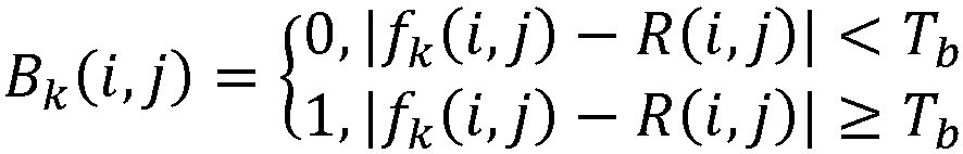
- calculating a first difference reference value of the L frames of images according to a second formula set, wherein the second formula set is:


- fk (i,j) is the grayscale value of the pixel point (i,j) in the k-th frame image, R(i,j) is the grayscale standard value of the pixel point (i,j), Tb is a grayscale difference threshold value between the grayscale value and the grayscale standard value of the same pixel point in the obstacle monitoring area, Bk (i,j) is a grayscale difference two-dimensional value of the pixel point (i,j) in the k-th frame image based on Tb , d is the obstacle monitoring area, Bk is a sum of the grayscale difference two-dimensional values of all the pixel points in the obstacle monitoring area of the k-th frame image, and B is a first difference reference value;
- determining that there is no obstacle in the obstacle monitoring area if the first difference reference value of the L frames of images is less than a first difference threshold value; and
- determining that there is an obstacle in the obstacle monitoring area if the first difference reference value of the L frames of images is greater than or equal to the first difference threshold.
- In this embodiment, the first difference reference value is configured to reflect the overall average difference between the grayscale values of all the pixel points in the obstacle monitoring area of L consecutive frames of images and the corresponding grayscale standard values. The first difference threshold value is configured to determine whether there is an obstacle in the background area and has a lower missed detection rate than monitoring each image individually.
- Therefore, this embodiment obtains the target image set through analyzing the inter-frame grayscale change in the background area of the target video data, calculates the grayscale standard value based on the target image set, and outputs the obstacle recognition result in the obstacle monitoring area according to the difference between the grayscale values of all the pixel points in the obstacle monitoring area in the subsequent images of the target image set and the corresponding grayscale standard values. This embodiment does not rely on feature matching and is not limited by the feature database, thereby reducing missed detections. In addition, this embodiment does not require to perform model training before use, and has lower requirements for computing power and processing speed during use, which helps to reduce implementation costs.
- It should be noted that the accuracy of the obstacle recognition algorithm in the present application depends on the stability of the road surface appearance. For scenes where the road surface appearance changes frequently, the accuracy thereof is difficult to guarantee. The highway area is a typical area with a stable road surface appearance, and the present application has a good effect on the highway area.
-
Fig. 2 shows a flow chart of obstacle recognition and road surface fluctuation recognition in one embodiment of the present application.Fig. 3 shows a flow chart for attempting to update a grayscale standard value in one embodiment of the present application. - Further, in one embodiment, after the step of determining a target image set from the target video data, it further comprises:
- aiming at each pixel point in the background area except the obstacle monitoring area, taking the average grayscale value of the same pixel point in the N frames of images as the grayscale standard value of the pixel point;
- after the step of determining that there is no obstacle in the obstacle monitoring area, further comprising:
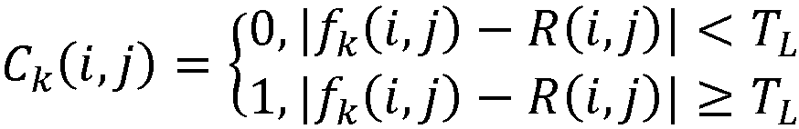
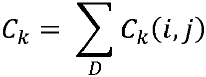
- calculating a second difference reference value of the L frames of images according to a third formula set, wherein the third formula set is:


- fk (i,j) is the grayscale value of the pixel point (i,j) in the k-th frame image, R(i,j) is the grayscale standard value of the pixel point (i,j), TL is the grayscale difference threshold value between the grayscale value and the grayscale standard value of the same pixel point in the background area, Ck (i,j) is the grayscale difference two-dimensional value of the pixel point (i,j) in the k-th frame image based on TL , D is the background area, Ck is the sum of the grayscale difference two-dimensional values of all the pixel points in the background area of the k-th frame image, and C is a second difference reference value;
- if the second difference reference value of the L frames of images is greater than or equal to a second difference threshold value, taking a first frame of the L frames of images as a starting frame, obtaining N consecutive frames of images from the target video data, and calculating the grayscale change reference value of the N frames of images, wherein N is equal to the number of image frames in the target image set; and
- if the grayscale change reference value of the N frames of images is less than the grayscale change threshold value, taking the N frames of images as a new target image set, and updating the grayscale standard value based on the new target image set.
- calculating a second difference reference value of the L frames of images according to a third formula set, wherein the third formula set is:
- This embodiment provides a method for updating a target image set and a grayscale standard value. As shown in
Fig. 2 andFig. 3 , after calculating the first difference reference value of L frames of images and determining that no obstacle exists, the second difference reference value of the L frames of images is further calculated. The second difference reference value is configured to reflect the overall average difference between the grayscale of all the pixel points in the background area of the continuous L frames of images and the corresponding grayscale standard values. The second difference threshold value is configured to define whether there is road surface fluctuation in the background area. For example, the overall color of the road surface in the image changes due to factors such as road surface material or external lighting, or it is possible that there are obstacles in areas outside the obstacle monitoring area. When it is determined that there is the road surface fluctuation according to the second difference reference value, an attempt is made to update the target image set and the grayscale standard value. - It should be noted that when it is determined that there is the road surface fluctuation, only one attempt operation is performed, that is, N consecutive frames of images are obtained to calculate the grayscale change reference value. If the grayscale change reference value meets the requirements, the target image set and the grayscale standard value are updated, otherwise no update is performed.
- Further, in one embodiment, after the step of aiming at each pixel point of the obstacle monitoring area, taking a grayscale average value of the same pixel point in the target image set as a grayscale standard value of the pixel point, it further comprises:
- obtaining N consecutive frames of images from the target video data regularly according to an update cycle, and calculating the grayscale change reference value of the N frames of images, wherein N is equal to the number of image frames in the target image set; and
- if the grayscale change reference value of the N frames of images is less than the grayscale change threshold value, taking the N frames of images as a new target image set, and updating the grayscale standard value based on the new target image set.
- This embodiment provides another method for updating the target image set and the grayscale standard value. As shown in
Fig. 3 , when the update cycle is reached, a trial operation is performed, that is, N consecutive frames of images are obtained to calculate the grayscale change reference value. If the grayscale change reference value meets the requirements, the target image set and the grayscale standard value are updated, otherwise no update is performed. For example, the vehicle attempts to update every 30 minutes of driving. - It should be noted that the above two updating methods can be used in combination. The first real-time fluctuation update strategy ensures that the grayscale standard value is updated in time when the road surface changes to a certain extent, and the second periodic update strategy ensures that a certain update frequency can be guaranteed even when the road surface changes slightly, thereby comprehensively improving the reliability of the grayscale standard value and ensuring the accuracy of the obstacle recognition algorithm.
- In the second aspect, the embodiment of the present application further provides a driving blind area monitoring apparatus.
-
Fig. 4 shows a functional module diagram of a driving blind area monitoring apparatus in one embodiment of the present application. - As shown in
Fig. 4 , in one embodiment, the driving blind area monitoring apparatus comprises: - an
area determination module 10, which is configured to determine a background area and an obstacle monitoring area from an area shot by a target camera, wherein the background area comprises the obstacle monitoring area; - a
preprocessing module 20, which is configured to preprocess video data collected by the target camera to obtain target video data; - an
image determination module 30, which is configured to determine a target image set from the target video data, wherein a grayscale change reference value of the target image set is less than a grayscale change threshold value, the grayscale change reference value of the target image set is calculated based on grayscale change quantization values of all two adjacent frames of images comprised in the set, and the grayscale change quantization value of the two adjacent frames of images is determined based on inter-frame grayscale change of the background area, and the greater the grayscale change, the greater the corresponding grayscale change quantization value; - a standard
value calculation module 40, which is configured to, aiming at each pixel point of the obstacle monitoring area, take a grayscale average value of the same pixel point in the target image set as a grayscale standard value of the pixel point; and - an
obstacle recognition module 50, which is configured to output an obstacle recognition result in the obstacle monitoring area according to a difference between grayscale values of all the pixel points in the obstacle monitoring area in the subsequent images of the target image set and corresponding grayscale standard values. - Further, in one embodiment, the
image determination module 30 is configured to: - obtain N consecutive frames of images from the target video data;
- calculate the grayscale change reference value of the N frames of images according to a first formula set, wherein the first formula set is:


- fk (i,j) is the grayscale value of the pixel point (i,j) in the k-th frame image, Tf is a grayscale difference threshold value of the same pixel point in the background area of two adjacent frames of images, Ak (i,j) is a grayscale difference two-dimensional value of the pixel point (i, j) between the k-th frame image and the (k-1)-th frame image, D is the background area, Ak is the grayscale change quantization value between the k-th frame image and the (k-1)-th frame image, and A is the grayscale change reference value; and
- determine the N frames of images as the target image set if the grayscale change reference value of the N frames of images is less than the grayscale change threshold value.
- Further, in one embodiment, the
obstacle recognition module 50 is configured to: - obtain L consecutive frames of images from the subsequent images of the target image set;
- calculate a first difference reference value of the L frames of images according to a second formula set, wherein the second formula set is:


- fk (i,j) is the grayscale value of the pixel point (i,j) in the k-th frame image, R(i,j) is the grayscale standard value of the pixel point (i,j), Tb is a grayscale difference threshold value between the grayscale value and the grayscale standard value of the same pixel point in the obstacle monitoring area, Bk (i,j) is a grayscale difference two-dimensional value of the pixel point (i,j) in the k-th frame image based on Tb , d is the obstacle monitoring area, Bk is a sum of the grayscale difference two-dimensional values of all the pixel points in the obstacle monitoring area of the k-th frame image, and B is a first difference reference value;
- determine that there is no obstacle in the obstacle monitoring area if the first difference reference value of the L frames of images is less than a first difference threshold value; and
- determine that there is an obstacle in the obstacle monitoring area if the first difference reference value of the L frames of images is greater than or equal to the first difference threshold.
- Further, in one embodiment, the standard
value calculation module 40 is further configured to: - aiming at each pixel point in the background area except the obstacle monitoring area, take the average grayscale value of the same pixel point in the N frames of images as the grayscale standard value of the pixel point;
- the driving blind area monitoring apparatus further comprises an update module, which is configured to:
- calculate a second difference reference value of the L frames of images according to a third formula set, wherein the third formula set is:

- fk (i,j) is the grayscale value of the pixel point (i,j) in the k-th frame image, R(i,j) is the grayscale standard value of the pixel point (i,j), TL is the grayscale difference threshold value between the grayscale value and the grayscale standard value of the same pixel point in the background area, Ck (i,j) is the grayscale difference two-dimensional value of the pixel point (i,j) in the k-th frame image based on TL , D is the background area, Ck is the sum of the grayscale difference two-dimensional values of all the pixel points in the background area of the k-th frame image, and C is a second difference reference value;
- if the second difference reference value of the L frames of images is greater than or equal to a second difference threshold value, take a first frame of the L frames of images as a starting frame, obtain N consecutive frames of images from the target video data, and calculate the grayscale change reference value of the N frames of images, wherein N is equal to the number of image frames in the target image set; and
- if the grayscale change reference value of the N frames of images is less than the grayscale change threshold value, take the N frames of images as a new target image set, and update the grayscale standard value based on the new target image set.
- calculate a second difference reference value of the L frames of images according to a third formula set, wherein the third formula set is:
- Further, in one embodiment, the driving blind area monitoring apparatus further comprises an update module, which is configured to:
- obtain N consecutive frames of images from the target video data regularly according to an update cycle, and calculate the grayscale change reference value of the N frames of images, wherein N is equal to the number of image frames in the target image set; and
- if the grayscale change reference value of the N frames of images is less than the grayscale change threshold value, take the N frames of images as a new target image set, and update the grayscale standard value based on the new target image set.
- Further, in one embodiment, the driving blind area monitoring apparatus further comprises a camera determination module, which is configured to:
- determine a lane wherein a vehicle is located based on a vehicle positioning system and a high-precision map; and
- if there is an adjacent lane on a left and/or right side of the lane where the vehicle is located, take the camera on a corresponding side of the vehicle as the target camera.
- Further, in one embodiment, the background area comprises all drivable areas in the area shot by the target camera, and the obstacle monitoring area is located in the adjacent lane area corresponding to the target camera.
- The function implementation of each module in the driving blind area monitoring apparatus corresponds to the steps in the driving blind area monitoring method in the above embodiment, and the function and implementation process thereof will not be repeated herein.
- In the third aspect, the embodiment of the present application provides a driving blind area monitoring device, and the driving blind area monitoring device can be a personal computer (PC), a laptop computer, a server, or other device with data processing capabilities.
-
Fig. 5 shows a hardware structure diagram of a driving blind area monitoring device involved in the embodiment of the present application. - As shown in
Fig. 5 , in the embodiment of the present application, the driving blind area monitoring device can comprise a processor, a memory, a communication interface, and a communication bus. - The communication bus can be of any type and is configured to interconnect the processor, the memory, and the communication interface.
- The communication interface comprises input/output (I/O) interfaces, physical interfaces, and logical interfaces, etc. These interfaces are configured to realize the interconnection of the components inside the driving blind area monitoring device, and the interconnection between the driving blind area monitoring device and other devices (such as other computing devices or user devices). The physical interface can be an Ethernet interface, an optical fiber interface, an ATM interface, etc. The user device can be a display, a keyboard, etc.
- The memory can be various types of storage media, such as random-access memory (RAM), read-only memory (ROM), non-volatile RAM (NVRAM), flash memory, optical storage, hard disk, programmable ROM (PROM), and electrically erasable PROM (EEPROM).
- The processor can be a general-purpose processor, which can call the driving blind area monitoring program stored in the memory and execute the driving blind area monitoring method provided in the embodiment of the present application. For example, the general-purpose processor can be a central processing unit (CPU). For method executed when the driving blind area monitoring program is called, reference can be made to various embodiments of the driving blind area monitoring method in the present application, which will not be repeated herein.
- Those skilled in the art can understand that the hardware structure shown in
Fig. 5 does not constitute a limitation of the present application, and can comprise more or less components than those shown inFig. 5 , or combine some components, or arrange different components. - In the fourth aspect, the embodiment of the present application further provides a storage medium.
- The readable storage medium of the present application stores the driving blind area monitoring program, wherein when the driving blind area monitoring program is executed by a processor, the steps of the above-mentioned driving blind area monitoring method are realized.
- For method executed when the driving blind area monitoring program is executed, reference can be made to various embodiments of the driving blind area monitoring method in the present application, which will not be repeated herein.
- It should be noted that the serial numbers of the above-mentioned embodiments of the present application are only for description and do not represent the advantages or disadvantages of the embodiments.
- From the description of the above embodiments, those skilled in the art can clearly understand that the methods of the above embodiments can be implemented by means of software plus a necessary general hardware platform, and of course hardware can also be used, but in many cases the former is better implementation. Based on this understanding, the technical solutions of the present application, in essence, or the parts that make contributions to the prior art, can be embodied in the form of software products. The computer software products are stored in a storage medium (such as ROM/RAM, magnetic disk, optical disk) as described above, comprising several instructions to make a terminal device execute the methods described in each embodiment of the present application.
- The above are only preferred embodiments of the present application, and are not intended to limit the protection scope of the present application. Any equivalent structure or equivalent process transformation made by using the contents of the description and drawings of the present application, or directly or indirectly applied in other related technical fields, are similarly comprised in the protection scope of patent of the present application.
Claims (10)
- A driving blind area monitoring method, comprising the following steps:determining a background area and an obstacle monitoring area from an area shot by a target camera, wherein the background area comprises the obstacle monitoring area;preprocessing video data collected by the target camera to obtain target video data;determining a target image set from the target video data, wherein a grayscale change reference value of the target image set is less than a grayscale change threshold value, the grayscale change reference value of the target image set is calculated based on grayscale change quantization values of all two adjacent frames of images comprised in the set, and the grayscale change quantization value of the two adjacent frames of images is determined based on inter-frame grayscale change of the background area, and the greater the grayscale change, the greater the corresponding grayscale change quantization value;aiming at each pixel point of the obstacle monitoring area, taking a grayscale average value of the same pixel point in the target image set as a grayscale standard value of the pixel point; andoutputting an obstacle recognition result in the obstacle monitoring area according to a difference between grayscale values of all the pixel points in the obstacle monitoring area in the subsequent images of the target image set and corresponding grayscale standard values.
- The driving blind area monitoring method according to claim 1, wherein the step of determining a target image set from the target video data comprises:obtaining N consecutive frames of images from the target video data;calculating the grayscale change reference value of the N frames of images according to a first formula set, wherein the first formula set is:


 fk (i,j) is the grayscale value of the pixel point (i,j) in the k-th frame image, Tf is a grayscale difference threshold value of the same pixel point in the background area of two adjacent frames of images, Ak (i,j) is a grayscale difference two-dimensional value of the pixel point (i, j) between the k-th frame image and the (k-1)-th frame image, D is the background area, Ak is the grayscale change quantization value between the k-th frame image and the (k-1)-th frame image, and A is the grayscale change reference value; anddetermining the N frames of images as the target image set if the grayscale change reference value of the N frames of images is less than the grayscale change threshold value.
 - The driving blind area monitoring method according to claim 1, wherein the step of outputting an obstacle recognition result in the obstacle monitoring area according to a difference between grayscale values of all the pixel points in the obstacle monitoring area in the subsequent images of the target image set and corresponding grayscale standard values comprises:obtaining L consecutive frames of images from the subsequent images of the target image set;calculating a first difference reference value of the L frames of images according to a second formula set, wherein the second formula set is:


 fk (i,j) is the grayscale value of the pixel point (i,j) in the k-th frame image, R(i,j) is the grayscale standard value of the pixel point (i,j), Tb is a grayscale difference threshold value between the grayscale value and the grayscale standard value of the same pixel point in the obstacle monitoring area, Bk (i,j) is a grayscale difference two-dimensional value of the pixel point (i,j) in the k-th frame image based on Tb , d is the obstacle monitoring area, Bk is a sum of the grayscale difference two-dimensional values of all the pixel points in the obstacle monitoring area of the k-th frame image, and B is a first difference reference value;determining that there is no obstacle in the obstacle monitoring area if the first difference reference value of the L frames of images is less than a first difference threshold value; anddetermining that there is an obstacle in the obstacle monitoring area if the first difference reference value of the L frames of images is greater than or equal to the first difference threshold.
 - The driving blind area monitoring method according to claim 3, wherein after the step of determining a target image set from the target video data, it further comprises:aiming at each pixel point in the background area except the obstacle monitoring area, taking the average grayscale value of the same pixel point in the N frames of images as the grayscale standard value of the pixel point;after the step of determining that there is no obstacle in the obstacle monitoring area, further comprising:calculating a second difference reference value of the L frames of images according to a third formula set, wherein the third formula set is:


 fk (i,j) is the grayscale value of the pixel point (i,j) in the k-th frame image, R(i,j) is the grayscale standard value of the pixel point (i,j), TL is the grayscale difference threshold value between the grayscale value and the grayscale standard value of the same pixel point in the background area, Ck (i,j) is the grayscale difference two-dimensional value of the pixel point (i,j) in the k-th frame image based on TL , D is the background area, Ck is the sum of the grayscale difference two-dimensional values of all the pixel points in the background area of the k-th frame image, and C is a second difference reference value;if the second difference reference value of the L frames of images is greater than or equal to a second difference threshold value, taking a first frame of the L frames of images as a starting frame, obtaining N consecutive frames of images from the target video data, and calculating the grayscale change reference value of the N frames of images, wherein N is equal to the number of image frames in the target image set; andif the grayscale change reference value of the N frames of images is less than the grayscale change threshold value, taking the N frames of images as a new target image set, and updating the grayscale standard value based on the new target image set.
 - The driving blind area monitoring method according to claim 1, wherein after the step of aiming at each pixel point of the obstacle monitoring area, taking a grayscale average value of the same pixel point in the target image set as a grayscale standard value of the pixel point, it further comprises:obtaining N consecutive frames of images from the target video data regularly according to an update cycle, and calculating the grayscale change reference value of the N frames of images, wherein N is equal to the number of image frames in the target image set; andif the grayscale change reference value of the N frames of images is less than the grayscale change threshold value, taking the N frames of images as a new target image set, and updating the grayscale standard value based on the new target image set.
- The driving blind area monitoring method according to any one of claims 1 to 5, wherein before the step of determining a background area and an obstacle monitoring area from an area shot by a target camera, it further comprises:determining a lane wherein a vehicle is located based on a vehicle positioning system and a high-precision map; andif there is an adjacent lane on a left and/or right side of the lane where the vehicle is located, taking the camera on a corresponding side of the vehicle as the target camera.
- The driving blind area monitoring method according to claim 6, wherein the background area comprises all drivable areas in the area shot by the target camera, and the obstacle monitoring area is located in the adjacent lane area corresponding to the target camera.
- A driving blind area monitoring apparatus, comprising:an area determination module, which is configured to determine a background area and an obstacle monitoring area from an area shot by a target camera, wherein the background area comprises the obstacle monitoring area;a preprocessing module, which is configured to preprocess video data collected by the target camera to obtain target video data;an image determination module, which is configured to determine a target image set from the target video data, wherein a grayscale change reference value of the target image set is less than a grayscale change threshold value, the grayscale change reference value of the target image set is calculated based on grayscale change quantization values of all two adjacent frames of images comprised in the set, and the grayscale change quantization value of the two adjacent frames of images is determined based on inter-frame grayscale change of the background area, and the greater the grayscale change, the greater the corresponding grayscale change quantization value;a standard value calculation module, which is configured to, aiming at each pixel point of the obstacle monitoring area, take a grayscale average value of the same pixel point in the target image set as a grayscale standard value of the pixel point; andan obstacle recognition module, which is configured to output an obstacle recognition result in the obstacle monitoring area according to a difference between grayscale values of all the pixel points in the obstacle monitoring area in the subsequent images of the target image set and corresponding grayscale standard values.
- A driving blind area monitoring device, comprising: a processor, a memory, and a driving blind area monitoring program that is stored on the memory and can be executed by the processor, wherein when the driving blind area monitoring program is executed by the processor, the steps of the driving blind area monitoring method according to any one of claims 1 to 7 are realized.
- A readable storage medium, comprising: a driving blind area monitoring program stored on the readable storage medium, wherein when the driving blind area monitoring program is executed by a processor, the steps of the driving blind area monitoring method according to any one of claims 1 to 7 are realized.
Applications Claiming Priority (2)
| Application Number | Priority Date | Filing Date | Title |
|---|---|---|---|
| CN202311233136.2A CN117315619B (en) | 2023-09-22 | 2023-09-22 | Driving blind area monitoring method, device, equipment and readable storage medium |
| PCT/CN2024/088761 WO2025060413A1 (en) | 2023-09-22 | 2024-04-19 | Driving blind spot monitoring method, apparatus and device, and readable storage medium |
Publications (2)
| Publication Number | Publication Date |
|---|---|
| EP4553794A1 true EP4553794A1 (en) | 2025-05-14 |
| EP4553794A4 EP4553794A4 (en) | 2026-01-14 |
Family
ID=89249215
Family Applications (1)
| Application Number | Title | Priority Date | Filing Date |
|---|---|---|---|
| EP24785958.0A Pending EP4553794A4 (en) | 2023-09-22 | 2024-04-19 | METHOD, DEVICE AND DEVICE FOR MONITORING A DRIVING BLIND POINT AND READABLE STORAGE MEDIUM |
Country Status (3)
| Country | Link |
|---|---|
| EP (1) | EP4553794A4 (en) |
| CN (1) | CN117315619B (en) |
| WO (1) | WO2025060413A1 (en) |
Families Citing this family (4)
| Publication number | Priority date | Publication date | Assignee | Title |
|---|---|---|---|---|
| CN117315619B (en) * | 2023-09-22 | 2024-12-31 | 东风商用车有限公司 | Driving blind area monitoring method, device, equipment and readable storage medium |
| CN119445296B (en) * | 2024-11-07 | 2025-08-29 | 深圳市小飞达电子有限公司 | A blind spot accuracy assessment method and system based on AI camera technology |
| CN120431141B (en) * | 2025-07-08 | 2025-09-16 | 龙岩学院 | Semitrailer hazard source monitoring method based on image fusion |
| CN120740863B (en) * | 2025-09-01 | 2025-11-21 | 延安大学 | Intelligent detection device and method for natural gas leakage |
Family Cites Families (6)
| Publication number | Priority date | Publication date | Assignee | Title |
|---|---|---|---|---|
| KR101122260B1 (en) * | 2009-12-29 | 2012-03-20 | 주식회사 바텍 | Methode and Apparatus for Obtaining Panoramic Image |
| JP7104916B2 (en) * | 2018-08-24 | 2022-07-22 | 国立大学法人岩手大学 | Moving object detection device and moving object detection method |
| CN111186432B (en) * | 2018-11-13 | 2021-05-28 | 杭州海康威视数字技术股份有限公司 | Method and device for early warning of vehicle blind spot |
| CN113642453A (en) * | 2021-08-11 | 2021-11-12 | 北京京东乾石科技有限公司 | Obstacle detection method, device and system |
| CN116092050B (en) * | 2022-12-29 | 2025-10-21 | 深圳市豪恩汽车电子装备股份有限公司 | Motor vehicle obstacle detection method, device and computer-readable storage medium |
| CN117315619B (en) * | 2023-09-22 | 2024-12-31 | 东风商用车有限公司 | Driving blind area monitoring method, device, equipment and readable storage medium |
-
2023
- 2023-09-22 CN CN202311233136.2A patent/CN117315619B/en active Active
-
2024
- 2024-04-19 WO PCT/CN2024/088761 patent/WO2025060413A1/en active Pending
- 2024-04-19 EP EP24785958.0A patent/EP4553794A4/en active Pending
Also Published As
| Publication number | Publication date |
|---|---|
| EP4553794A4 (en) | 2026-01-14 |
| CN117315619B (en) | 2024-12-31 |
| CN117315619A (en) | 2023-12-29 |
| WO2025060413A1 (en) | 2025-03-27 |
Similar Documents
| Publication | Publication Date | Title |
|---|---|---|
| EP4553794A1 (en) | Driving blind spot monitoring method, apparatus and device, and readable storage medium | |
| CN110889351B (en) | Video detection method, device, terminal equipment and readable storage medium | |
| KR101163446B1 (en) | A lane departure warning system using a virtual lane and a system according to the same | |
| CN113139482A (en) | Method and device for detecting traffic abnormity | |
| US8457408B2 (en) | Method and system of identifying one or more features represented in a plurality of sensor acquired data sets | |
| US20190251372A1 (en) | System and method for lane detection | |
| JP2001357484A (en) | Road abnormality detection device | |
| US20220148316A1 (en) | Method and device for determining road operation condition, and storage medium | |
| CN113076851B (en) | Method and device for collecting vehicle violation data and computer equipment | |
| CN111428644A (en) | Zebra crossing region monitoring method, system and medium based on deep neural network | |
| CN107346547B (en) | Monocular platform-based real-time foreground extraction method and device | |
| CN108162858A (en) | Vehicle-mounted monitoring apparatus and its method | |
| CN114898325A (en) | Vehicle dangerous lane change detection method and device and electronic equipment | |
| CN113255612A (en) | Preceding vehicle starting reminding method and system, electronic device and storage medium | |
| US12403936B2 (en) | Method for controlling a driver assistance system during operation of a vehicle | |
| RU2853014C1 (en) | Method, apparatus, device and readable data storage medium for monitoring a blind spot when driving | |
| CN119785162A (en) | A method to improve event detection accuracy based on multi-model fusion | |
| US20240212196A1 (en) | Methods and devices for setting a threshold in an object detection system | |
| KR100383538B1 (en) | Method and system for warning departure of traffic lane | |
| CN110556024B (en) | Anti-collision auxiliary driving method and system and computer readable storage medium | |
| CN106128105A (en) | A kind of traffic intersection pedestrian behavior monitoring system | |
| CN118991606A (en) | Blind area collision early warning method and system | |
| JPH08320998A (en) | Lane marker detection device | |
| CN111091096B (en) | Vehicle deviation decision method and device, storage medium and vehicle | |
| CN118506321A (en) | BSD camera deviation warning method, device and electronic equipment |
Legal Events
| Date | Code | Title | Description |
|---|---|---|---|
| STAA | Information on the status of an ep patent application or granted ep patent |
Free format text: STATUS: UNKNOWN |
|
| STAA | Information on the status of an ep patent application or granted ep patent |
Free format text: STATUS: THE INTERNATIONAL PUBLICATION HAS BEEN MADE |
|
| PUAI | Public reference made under article 153(3) epc to a published international application that has entered the european phase |
Free format text: ORIGINAL CODE: 0009012 |
|
| STAA | Information on the status of an ep patent application or granted ep patent |
Free format text: STATUS: REQUEST FOR EXAMINATION WAS MADE |
|
| 17P | Request for examination filed |
Effective date: 20241014 |
|
| AK | Designated contracting states |
Kind code of ref document: A1 Designated state(s): AL AT BE BG CH CY CZ DE DK EE ES FI FR GB GR HR HU IE IS IT LI LT LU LV MC ME MK MT NL NO PL PT RO RS SE SI SK SM TR |
|
| A4 | Supplementary search report drawn up and despatched |
Effective date: 20251215 |
|
| RIC1 | Information provided on ipc code assigned before grant |
Ipc: G06V 20/58 20220101AFI20251209BHEP Ipc: G06V 20/40 20220101ALI20251209BHEP Ipc: G06V 10/764 20220101ALI20251209BHEP Ipc: G06T 7/254 20170101ALI20251209BHEP Ipc: G06T 7/73 20170101ALI20251209BHEP |