EP4553581A1 - Image forming apparatus - Google Patents
Image forming apparatus Download PDFInfo
- Publication number
- EP4553581A1 EP4553581A1 EP24204281.0A EP24204281A EP4553581A1 EP 4553581 A1 EP4553581 A1 EP 4553581A1 EP 24204281 A EP24204281 A EP 24204281A EP 4553581 A1 EP4553581 A1 EP 4553581A1
- Authority
- EP
- European Patent Office
- Prior art keywords
- members
- primary transfer
- holding
- roller
- frame
- Prior art date
- Legal status (The legal status is an assumption and is not a legal conclusion. Google has not performed a legal analysis and makes no representation as to the accuracy of the status listed.)
- Granted
Links
Images



Classifications
-
- G—PHYSICS
- G03—PHOTOGRAPHY; CINEMATOGRAPHY; ANALOGOUS TECHNIQUES USING WAVES OTHER THAN OPTICAL WAVES; ELECTROGRAPHY; HOLOGRAPHY
- G03G—ELECTROGRAPHY; ELECTROPHOTOGRAPHY; MAGNETOGRAPHY
- G03G15/00—Apparatus for electrographic processes using a charge pattern
- G03G15/01—Apparatus for electrographic processes using a charge pattern for producing multicoloured copies
- G03G15/0142—Structure of complete machines
- G03G15/0178—Structure of complete machines using more than one reusable electrographic recording member, e.g. one for every monocolour image
- G03G15/0189—Structure of complete machines using more than one reusable electrographic recording member, e.g. one for every monocolour image primary transfer to an intermediate transfer belt
-
- G—PHYSICS
- G03—PHOTOGRAPHY; CINEMATOGRAPHY; ANALOGOUS TECHNIQUES USING WAVES OTHER THAN OPTICAL WAVES; ELECTROGRAPHY; HOLOGRAPHY
- G03G—ELECTROGRAPHY; ELECTROPHOTOGRAPHY; MAGNETOGRAPHY
- G03G15/00—Apparatus for electrographic processes using a charge pattern
- G03G15/01—Apparatus for electrographic processes using a charge pattern for producing multicoloured copies
- G03G15/0105—Details of unit
- G03G15/0131—Details of unit for transferring a pattern to a second base
- G03G15/0136—Details of unit for transferring a pattern to a second base transfer member separable from recording member or vice versa, mode switching
-
- G—PHYSICS
- G03—PHOTOGRAPHY; CINEMATOGRAPHY; ANALOGOUS TECHNIQUES USING WAVES OTHER THAN OPTICAL WAVES; ELECTROGRAPHY; HOLOGRAPHY
- G03G—ELECTROGRAPHY; ELECTROPHOTOGRAPHY; MAGNETOGRAPHY
- G03G15/00—Apparatus for electrographic processes using a charge pattern
- G03G15/14—Apparatus for electrographic processes using a charge pattern for transferring a pattern to a second base
- G03G15/16—Apparatus for electrographic processes using a charge pattern for transferring a pattern to a second base of a toner pattern, e.g. a powder pattern, e.g. magnetic transfer
- G03G15/1605—Apparatus for electrographic processes using a charge pattern for transferring a pattern to a second base of a toner pattern, e.g. a powder pattern, e.g. magnetic transfer using at least one intermediate support
-
- G—PHYSICS
- G03—PHOTOGRAPHY; CINEMATOGRAPHY; ANALOGOUS TECHNIQUES USING WAVES OTHER THAN OPTICAL WAVES; ELECTROGRAPHY; HOLOGRAPHY
- G03G—ELECTROGRAPHY; ELECTROPHOTOGRAPHY; MAGNETOGRAPHY
- G03G2215/00—Apparatus for electrophotographic processes
- G03G2215/00135—Handling of parts of the apparatus
- G03G2215/00139—Belt
- G03G2215/00143—Meandering prevention
-
- G—PHYSICS
- G03—PHOTOGRAPHY; CINEMATOGRAPHY; ANALOGOUS TECHNIQUES USING WAVES OTHER THAN OPTICAL WAVES; ELECTROGRAPHY; HOLOGRAPHY
- G03G—ELECTROGRAPHY; ELECTROPHOTOGRAPHY; MAGNETOGRAPHY
- G03G2215/00—Apparatus for electrophotographic processes
- G03G2215/01—Apparatus for electrophotographic processes for producing multicoloured copies
- G03G2215/0103—Plural electrographic recording members
- G03G2215/0119—Linear arrangement adjacent plural transfer points
- G03G2215/0122—Linear arrangement adjacent plural transfer points primary transfer to an intermediate transfer belt
- G03G2215/0125—Linear arrangement adjacent plural transfer points primary transfer to an intermediate transfer belt the linear arrangement being horizontal or slanted
- G03G2215/0132—Linear arrangement adjacent plural transfer points primary transfer to an intermediate transfer belt the linear arrangement being horizontal or slanted vertical medium transport path at the secondary transfer
Definitions
- Embodiments of the present disclosure relate to an image forming apparatus.
- a technology is known that primary transfer rollers for colors other than black are separated from the photoconductors corresponding to the colors in the monochrome mode.
- a holding member is disposed for each of the primary transfer roller and a backup roller, and the primary transfer roller and the backup roller are separated from the photoconductor by a moving mechanism.
- the backup roller is a roller for determining the shape of an intermediate transfer belt to set a transfer nip between the primary transfer roller and the backup roller on the most upstream side in a rotation direction of the intermediate transfer belt to a target condition.
- the holding member is disposed for each of the primary transfer roller and the backup roller, the distance between the primary transfer roller and the backup roller is increased, so that the image forming apparatus is increased in size, and thus the manufacturing cost of the image forming apparatus is increased (see Japanese Unexamined Patent Application Publication No. 2013-113907 ).
- primary transfer rollers for colors cyan, magenta, and yellow
- a backup roller are held by the same holding member, and when a monochrome mode and a full-color mode is switched, the entire holding member is moved to contact or separate the primary transfer rollers.
- the front and rear (left-and-right) ends of the primary transfer roller and the backup roller for color need to be held by the same holding member, and thus the size of the components increases, and the manufacturing cost of the image forming apparatus increases (see Japanese Unexamined Patent Application Publication No. 2008-122596 ).
- a mechanism for holding the primary transfer roller and the backup roller by the same holding member and a configuration for positioning the holding member by contacting the holding member against a transfer frame are proposed.
- the photoconductor is not positioned with respect to the transfer frame.
- the position of the primary transfer roller with respect to the photoconductor is likely to vary due to the accumulation of tolerances of components.
- the image density deviation is likely to occur in an output image between the left and right.
- a restriction mechanism for restricting belt meandering is not installed, causing an inconvenience that an expensive belt needs to be used or the life of the belt is short (see Japanese Unexamined Patent Application Publication No. 2010-197774 ).
- An object of the present disclosure is to provide an image forming apparatus that includes an intermediate transferor that can be easily inserted into and removed from a body of the image forming apparatus, is compact and inexpensive, is less likely to cause image density deviation, and has a long life.
- an image forming apparatus includes a plurality of image bearers, a plurality of frame members, a plurality of contact members, an intermediate transferor, a plurality of primary transfer members, a plurality of holding members, an intermediate transferor frame, a plurality of pressure members, and a plurality of pressing members.
- the plurality of image bearers bear toner images.
- the plurality of frame members hold the plurality of image bearers, respectively.
- the plurality of contact members position the plurality of image bearers, respectively.
- the intermediate transferor is movable to secondarily transfer the toner images primarily transferred from the plurality of image bearers onto a recording medium.
- the plurality of primary transfer members primarily transfer the toner images from the plurality of image bearers onto the intermediate transferor at primary transfer portions, respectively, at which the plurality of image bearers contact an outer circumferential surface of the intermediate transferor.
- the plurality of holding members hold the plurality of primary transfer members, respectively.
- the intermediate transferor frame holds the intermediate transferor and the plurality of holding members, with the plurality of holding members being rotatable.
- the plurality of pressure members press the plurality of holding members.
- the plurality of pressing members press the plurality of frame members and the plurality of contact members toward the intermediate transferor frame or a body structure side plate.
- One end of the plurality of image bearers is positioned with the plurality of frame members and the plurality of contact members pressed toward the intermediate transferor frame by the plurality of pressing members.
- the plurality of primary transfer members are positioned on a same side as the one end, with the plurality of holding members contacted against the intermediate transferor frame by the plurality of pressure members.
- an image forming apparatus can be provided that includes an intermediate transferor easily inserted into and removed from a body of the image forming apparatus, is compact and inexpensive, is less likely to cause image density deviation, and has a long life.
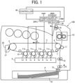
- FIG. 1 is a diagram illustrating an example of an image forming apparatus 100 configured as a printer.
- the image forming apparatus 100 illustrated in FIG. 1 is provided with a plurality of photoconductors (an example of image bearers), for example, first to fourth photoconductors 1a, 1b, 1c, and 1d (hereinafter, referred to as "photoconductor 1" as appropriate when colors are not distinguished) in FIG. 1 in a body of the image forming apparatus 100. Toner images in different colors are formed on the respective photoconductors.
- photoconductors an example of image bearers
- photoconductors 1a, 1b, 1c, and 1d hereinafter, referred to as "photoconductor 1" as appropriate when colors are not distinguished
- a black toner image, a magenta toner image, a cyan toner image, and a yellow toner image are formed on the photoconductors 1a, 1b, 1c, and 1d, respectively.
- the photoconductors 1a, 1b, 1c, and 1d in FIG. 1 are drum-shaped photoconductors but may be endless-belt shaped photoconductor belts to rotate while being wound around multiple rollers.
- An intermediate transfer belt 3 as an intermediate transfer member is disposed facing the first to fourth photoconductors 1a, 1b, 1c, and 1d.
- the photoconductors 1a, 1b, 1c, and 1d contact the surface of the intermediate transfer belt 3.
- the intermediate transfer belt 3 secondarily transfers toner images, which have been primarily transferred to the intermediate transfer belt 3 from the photoconductors 1a, 1b, 1c, and 1d onto a recording medium P.
- the intermediate transfer belt 3 illustrated in FIG. 1 is wound around a drive roller 4, a tension roller 5, and an entrance roller 7.
- One of these support rollers, for example, the support roller 4 functions as a drive roller driven by a drive source.
- the intermediate transfer belt 3 is rotated by the drive of the drive roller in the direction illustrated by arrow A.
- the intermediate transfer belt 3 may include either a plurality of layers or a single layer.
- the plurality of layers preferably includes a base layer having an outer circumferential surface coated by a smooth coating layer made of, e.g., fluorine-based resin.
- the base layer may be made of, for example, a stretch-resistant fluororesin, polyvinylidene difluoride (PVDF) sheet, or polyimide resin.
- the single layer may be preferably made of, for example, PVDF, polycarbonate (PC), or polyimide.
- the configuration for forming toner images on the photoconductors 1a, 1b, 1c, and 1d and the configuration for transferring the toner images onto the intermediate transfer belt 3 are all substantially the same, except the colors of the respective toner images formed on the photoconductors 1a, 1b, 1c, and 1d. Accordingly, a description is given of only the configuration and operation for forming a black toner image on the first photoconductor 1a and transferring the black toner image onto the intermediate transfer belt 3.
- the photoconductor 1a is rotated in a counterclockwise direction as indicated by the arrow A in FIG. 1 .
- the surface of the photoconductor 1a is irradiated with light from a charge elimination device, so that the surface potential of the photoconductor 1a is initialized.
- the initialized surface of the photoconductor 1a is uniformly charged to a specified polarity, e.g., a negative polarity in this example by a charging device 8.
- the charged surface is irradiated with a light-modulated laser beam L emitted from an exposure device 9.
- electrostatic latent images corresponding to image data are formed on the surface of the photoconductor 1a.
- the exposure device 9 as a laser writing device that emits a laser beam is used.
- an exposure device having a light-emitting diode (LED) array and an imaging device can also be used.
- the electrostatic latent image formed on the photoconductor 1a is visualized as a visible black toner image when the electrostatic latent image passes a developing device 10.
- primary transfer rollers 11a, 11b, 11c, and 11d (hereinafter, referred to as a "primary transfer roller 11" as appropriate when colors are not distinguished) as primary transfer members positioned substantially opposite to the photoconductors 1a, 1b, 1c, and 1d via the intermediate transfer belt 3 are arranged.
- the primary transfer roller 11 contacts the back surface of the intermediate transfer belt 3, so that an appropriate transfer nip between the photoconductor 1a and the intermediate transfer belt 3 is ensured.
- a transfer voltage having a polarity (e.g., a positive polarity in this example) opposite to the toner charge polarity of the toner image formed on the photoconductor 1a is applied to the primary transfer roller 11. Accordingly, a transfer electric field is formed between the photoconductor 1a and the intermediate transfer belt 3, and in the primary transfer section where the photoconductor 1a and the outer circumferential surface of the intermediate transfer belt 3 contact with each other, the toner image on the photoconductor 1a is electrostatically transferred onto the intermediate transfer belt 3 which is rotated in synchronization with the photoconductor 1a (primary transfer process). Untransferred toner adhering to the surface of the photoconductor 1a after the toner image is transferred to the intermediate transfer belt 3 is removed by a cleaning device, and the surface of the photoconductor 1a is cleaned.
- a polarity e.g., a positive polarity in this example
- a magenta toner image, a cyan toner image, and a yellow toner image are formed on the second to fourth photoconductors 1b, 1c, and 1d, respectively.
- the toner images of the respective colors are sequentially superimposed and electrostatically transferred onto the intermediate transfer belt 3 on which the black toner image is transferred.
- the image forming apparatus 100 has two types of modes, which are a full-color mode in which four color toner images are used and a black monochrome mode in which a black toner image alone is used.
- a full-color mode the intermediate transfer belt 3 and the photoconductors 1 of four colors contact with each other, and toner of all four colors is transferred onto the intermediate transfer belt 3.
- the black monochrome mode only the black photoconductor 1a contacts the intermediate transfer belt 3 and only the black toner is transferred onto the intermediate transfer belt 3.
- the intermediate transfer belt 3 and the magenta, cyan, and yellow photoconductors 1b, 1c, and 1d are not contacted with each other, and the primary transfer rollers 11b, 11c, and 11d are separated from the photoconductors 1b, 1c, and 1d by a contact-and-separation mechanism 90 included in the image forming apparatus 100.
- a sheet feeding device 14 is disposed in a lower portion of the apparatus body, and the sheet feeding device 14 feeds a recording medium P made of, for example, a transfer paper in a direction indicated by arrow B by rotation of a sheet feed roller 15.
- the recording medium P that has been sent out is fed by a registration roller pair 16 at a specified timing to between a portion of the intermediate transfer belt 3 wound around the support roller 4 and a secondary transfer roller 17 that is opposite the portion of the intermediate transfer belt 3.
- a specified transfer voltage is applied to the secondary transfer roller 17, and thus the composite toner image on the intermediate transfer belt 3 is secondarily transferred onto the recording medium P.
- the recording medium P on which the composite toner image is secondarily transferred is further conveyed upward and passes a fixing device 18. At this time, the toner image on the recording medium P is fixed by the action of heat and pressure.
- the recording medium P that has passed the fixing device 18 is ejected to the outside of the image forming apparatus 100 via a sheet ejection roller pair 19 disposed in a sheet ejection section.
- the untransferred toner adhering to the intermediate transfer belt 3 after transfer of the toner image is removed by a belt cleaner 20.
- the belt cleaner 20 according to the present embodiment includes a cleaning blade 21 having a blade shape made of, for example, urethane.
- the cleaning blade 21 contacts the outer circumferential surface of the intermediate transfer belt 3 in a counter direction with respect to the moving direction of the intermediate transfer belt 3.
- various types of belt cleaners can be used as the belt cleaner 20 as appropriate, and for example, the belt cleaner 20 may be a capacitance type.
- the untransferred toner removed from the intermediate transfer belt 3 by the cleaning blade 21 is sent to the rear side in a longitudinal direction by a waste-toner coil in a cleaning case of the belt cleaner 20, and is conveyed to a waste-toner container via a waste-toner passage disposed in the apparatus body.
- FIG. 1 illustrates an example of a diagram of an applied power supply used in the present embodiment.
- a primary-transfer-bias power supply 27BK that is a primary transfer power supply for applying a voltage to the primary transfer roller 11a is connected to a detector 28 and a controller 30.
- the detector 28 is connected to the primary-transfer-bias power supply 27BK, the primary transfer roller 11a, and the controller 30.
- the detector 28 is connected to only the primary transfer roller 11a corresponding to the photoconductor 1a of one color (black in the present embodiment) of the photoconductors 1a, 1b, 1c, and 1d of all colors.
- the detector 28 is a primary-transfer-current detector that detects the amount of current flowing through the primary transfer roller 11a when a bias is applied to the primary transfer roller 11a.
- the detector 28 detects an output bias of the primary-transfer-bias power supply 27BK.
- the image forming apparatus 100 includes a plurality of primary-transfer-bias power supplies 27BK and 29FC, one of which is coupled with the primary transfer roller 11a corresponding to the photoconductor 1a for the black toner image, and the detector 28 is also coupled only with the primary transfer roller 11a corresponding to the photoconductor 1a for the black toner image.
- the image forming apparatus 100 need only include one detector 28, which reduces the costs of the configuration of an intermediate transferor unit 60 and the resistance detection configuration. Control for changing the target value of the transfer bias over time and every time the environment changes is unnecessary. Driving the intermediate transfer device and the image bearer each time is not necessary, so that the life of the intermediate transfer member and the image bearer can be extended.
- the controller 30 is connected to the primary-transfer-bias power supply 27BK, the primary-transfer-bias power supply 29FC, and the detector 28, and determines the primary transfer voltage of the primary transfer roller 11a corresponding to all colors on the basis of a detection result by the detector 28, that is, the current value X detected by the detector 28.
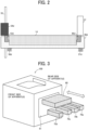
- FIG. 2 is a schematic view of an image forming apparatus according to an embodiment of the present disclosure.
- the photoconductors 1a, 1b, 1c, and 1d are held by photoconductor frames 49a, 49b, 49c, and 49d (examples of frame members), respectively.
- FIG. 2 representatively illustrates, for example, a photoconductor 1d and a photoconductor frame 49d on the front side of the image forming apparatus 100.
- Contact members are disposed at both ends of each of the photoconductors 1a, 1b, 1c, and 1d in the longitudinal direction. Specifically, in FIG.
- a photoconductor contact member 48d is disposed on the front side of the photoconductor 1d in the removal direction
- a photoconductor contact member 53d is disposed on the rear side of the photoconductor 1d in the removal direction.
- the photoconductor frame 49d (an example of a frame member) that holds the photoconductor 1d is disposed.
- a photoconductor pressing member 57d (an example of a pressing member) is disposed on the front side of the photoconductor frame 49d in the removal direction.
- a photoconductor pressing member 58d is disposed on the rear side of the photoconductor frame 49d in the removal direction.
- the photoconductor contact members 48d and 53d are contacted against contacted members by the photoconductor pressing members 57d and 58d to position the photoconductors 1a, 1b, 1c, and 1d.
- the contacted members against which the photoconductor contact members 48d and 53d contact are different.
- the photoconductor contact member 48d on the front side in the removal direction is positioned by contacting against an intermediate transferor frame 37 or another member disposed on the intermediate transferor frame 37.
- the photoconductor contact member 53d on the rear side in the removal direction is positioned by contacting against a body structure side plate 55 or a body side plate holder 54d disposed on the body structure side plate 55.
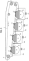
- FIG. 3 is a diagram illustrating the insertion and removal directions of the intermediate transferor unit and the photoconductor unit into and from the image forming apparatus.
- the intermediate transferor unit 60 and photoconductor units 70a, 70b, 70c, and 70d can be easily inserted into and removed from the image forming apparatus 100 from the right to the left or from the left to the right when viewed from the front of the apparatus.
- the insertion and removal directions of the intermediate transferor unit 60 are parallel to the insertion and removal directions of the photoconductor units 70a, 70b, 70c, and 70d.
- the intermediate transferor unit 60 includes the intermediate transfer belt 3, the drive roller 4, the tension roller 5, the entrance roller 7, the belt cleaner 20, and the four primary transfer rollers 11a, 11b, 11c, and 11d (see FIG. 1 ).
- the photoconductor units 70a, 70b, 70c, and 70d include the four photoconductors 1a, 1b, 1c, and 1d, and four charging devices 8, respectively (see FIG. 1 ).
- FIG. 4 is a schematic view of an intermediate transfer unit and a photoconductor unit on the rear side in the removal direction.
- FIG. 5 is a schematic view of the intermediate transfer unit and the photoconductor unit on the front side in the removal direction.
- the photoconductors 1a, 1b, 1c, and 1d are positioned by photoconductor pressing members 58a, 58b, 58c, and 58d as first pressing members that bring photoconductor contact members 53a, 53b, 53c, and 53d into contact with body side plate holders 54a, 54b, 54c, and 54d, respectively, disposed on the body structure side plate 55.
- photoconductors 1a, 1b, 1c, and 1d are positioned by photoconductor pressing members 58a, 58b, 58c, and 58d as first pressing members that bring photoconductor contact members 53a, 53b, 53c, and 53d into contact with body side plate holders 54a, 54b, 54c, and 54d, respectively, disposed
- the photoconductors 1a, 1b, 1c, and 1d are positioned by photoconductor pressing members 57a, 57b, 57c, and 57d as second pressing members that bring photoconductor contact members 48a, 48b, 48c, and 48d, respectively, into contact with the intermediate transferor frame 37 or another member disposed on the intermediate transferor frame 37.
- FIG. 6 is a diagram illustrating the positions of the primary transfer rollers 11a, 11b, 11c, and 11d on the rear side in the removal direction of the intermediate transferor unit.
- FIG. 7 is a diagram illustrating the positions of the primary transfer rollers 11a, 11b, 11c, and 11d on the front side in the removal direction of the intermediate transferor unit.
- the primary transfer rollers 11a, 11b, 11c, and 11d for the respective colors are held by primary-transfer-roller holding members 51a, 51b, 51c, and 51d (examples of holding members), respectively.
- First pressure members 50a, 50b, 50c, and 50d that press the primary transfer rollers 11a, 11b, 11c, and 11d are disposed on the primary-transfer-roller holding members 51a, 51b, 51c, and 51d, respectively.
- the primary-transfer-roller holding members 51a, 51b, 51c, and 51d can rotate around rotation shafts 52a, 52b, 52c, and 52d by the pressing force of the first pressure members 50a, 50b, 50c, and 50d.
- Such a configuration minimizes the variation in the positional relation of the primary transfer rollers 11a, 11b, 11c, and 11d with respect to the photoconductors 1a, 1b, 1c, and 1d, and reduces the variation in image density.
- Such a configuration facilitates the insertion and removal of the intermediate transferor unit 60 into and from the apparatus body, and realizes reducing the size and cost of the apparatus.
- the intermediate transferor frame 37 holds the intermediate transfer belt 3 and rotatably holds primary-transfer-roller holding members 51a, 51b, 51c, and 51d.
- the primary transfer rollers 11a, 11b, 11c, and 11d are held by primary-transfer-roller holding members 81a, 81b, 81c, and 81d (examples of holding members), respectively.
- Second pressure members 80a, 80b, 80c, and 80d that press the primary transfer rollers 11a, 11b, 11c, and 11d are disposed in the primary-transfer-roller holding members 81a, 81b, 81c, and 81d.
- the primary-transfer-roller holding members 81a, 81b, 81c, and 81d can rotate around the rotation shafts 52a, 52b, 52c, and 52d by the pressing force of the second pressure members 80a, 80b, 80c, and 80d.
- Contacting portions 86a, 86b, 86c, and 86d formed at the lower portions of the primary-transfer-roller holding members 81a, 81b, 81c, and 81d contact the intermediate transferor frame 37.
- the primary transfer roller holding members 81a, 81b, 81c, and 81d are contacted against the intermediate transferor frame 37 by the second pressure members 80a, 80b, 80c, and 80d to position the primary transfer rollers 11a, 11b, 11c, and 11d, respectively.
- the intermediate transferor frame 37 holds the intermediate transfer belt 3 and rotatably holds the primary-transfer-roller holding members 81a, 81b, 81c, and 81d.
- the positional variation of the primary transfer rollers 11a, 11b, 11c, and 11d with respect to the photoconductors 1a, 1b, 1c, and 1d does not increase.
- the positions of the photoconductors 1a, 1b, 1c, 1d on the front side in the removal direction are determined by bringing the photoconductor contact members 48a, 48b, 48c, 48d into contact with the intermediate transferor frame 37.
- the positional variation of the primary transfer rollers 11a, 11b, 11c, and 11d with respect to the photoconductors 1a, 1b, 1c, and 1d does not increase.
- the smaller the positional variation of the primary transfer rollers 11a, 11b, 11c, and 11d with respect to the photoconductors 1a, 1b, 1c, and 1d the smaller the variation in the image density at the rear and front sides in the removal direction, and thus the preferable images can be provided.
- the primary-transfer-roller holding members 81a, 81b, 81c, and 81d are contacted against the intermediate transferor frame 37 ( FIG. 7 ) after one end of each of the photoconductors 1a, 1b, 1c, and 1d is contacted against one end of the intermediate transferor frame 37 to position the photoconductors 1a, 1b, 1c, and 1d and the intermediate transferor frame 37 ( FIG. 5 ), so that the primary transfer rollers 11a, 11b, 11c, and 11d on one end can be positioned with high precision.
- the intermediate transferor unit 60 can be attached and detached in the main scanning direction, the intermediate transferor unit 60 also can be easily attached to and detached from the apparatus body.
- each of the photoconductors 1a, 1b, 1c, and 1d is positioned by being pressed by the body structure side plate 55 of in consideration of the ease of attachment and detachment of the intermediate transferor unit 60 ( FIG. 4 ).
- the primary transfer roller holding members 81a, 81b, 81c, and 81d are contacted against the photoconductor frames 49a, 49b, 49c, and 49d in order to determine the positions of the primary transfer roller holding members 81a, 81b, 81c, and 81d on the other end.
- Such a configuration can accurately determine the positions of the primary transfer rollers 11a, 11b, 11c, and 11d with respect to the photoconductors 1a, 1b, 1c, and 1d, so that the deviation of the image density is reduced.
- a backup roller 47 that contacts the inner circumference of the intermediate transfer belt 3 to rotate is disposed upstream from the primary transfer rollers 11a, 11b, 11c, and 11d for the respective colors.
- Such a configuration can form the shape of the transfer nip that is formed between the photoconductor 1d and the intermediate transfer belt 3 and located at the most upstream side as intended.
- the backup roller 47 is held at both ends ( FIGS. 6 and 7 ) by the primary-transfer-roller holding members 51d and 81d located on the most upstream side (yellow in the present embodiment) in the rotation direction of the intermediate transfer belt 3.
- the primary-transfer-roller holding members 51d and 81d are second holding members that hold the backup roller 47.
- the holding member that holds the most upstream primary transfer roller 11d among the plurality of primary transfer rollers 11a, 11b, 11c, and 11d and the second holding member that holds the backup roller 47 are the same member.
- a backup roller pressure member 72 (see FIG. 10 ) as a third pressure member, the first pressure members 50a, 50b, 50c, and 50d ( FIG. 6 ), and the second pressure members 80a, 80b, 80c, and 80d ( FIG. 7 ) are the same members.
- the other primary transfer rollers 11a, 11b, and 11c are held at both ends ( FIGS.
- the contact-and-separation mechanism 90 is disposed that contacts and separates the primary transfer rollers 11a, 11b, 11c, and 11d against and from the intermediate transfer belt 3 to contact and separate the intermediate transfer belt 3 against and from the photoconductors 1a, 1b, 1c, and 1d (see FIG. 10 ).
- Such a configuration can downsize the image forming apparatus 100, can reduce the manufacturing cost, and can simplify the apparatus structure as compared with the case where the backup roller 47 is separately disposed.
- the second holding member that holds the backup roller is positioned to the photoconductor frames 49a, 49b, 49c, and 49d ( FIG. 6 ) or the intermediate transferor frame 37 ( FIG. 7 ).
- a belt skew correction mechanism 150 is provided for the tension roller 5, which is a rotator that is positioned upstream from the backup roller 47 and is inclinable to support the intermediate transfer belt 3.
- the belt skew correction mechanism 150 inclines the tension roller 5 to correct the skew of the intermediate transfer belt 3.
- the belt skew correction mechanism 150 is disposed so that the durability against cracking of the intermediate transfer belt 3 can be enhanced and the life of the intermediate transfer belt 3 can be extended.
- FIG. 8 is a schematic view of the belt skew correction mechanism that corrects the skew of the belt.
- the belt skew correction mechanism 150 is a correction mechanism that corrects the skew of the belt by inclining the tension roller 5.
- the belt skew correction mechanism 150 is disposed at an end of the tension roller 5 in the axial direction and includes a belt end detecting member 130 and a belt position correction unit 140.
- the belt end detecting member 130 has a cylindrical shape and is disposed on a roller shaft 5a of the tension roller 5 to be movable in the roller axis direction.
- the belt end detecting member 130 has a flat portion 130a extending substantially perpendicularly to the roller axis direction.
- the periphery of the flat portion 130a is formed in a circular shape, and the center of the circle is on the axis of the tension roller 5.
- the flat portion 130a functions as a belt contact portion with which an end (belt end 3a) of the intermediate transfer belt 3 contacts when the intermediate transfer belt 3 moves outward in the roller axial direction.
- the roller shaft 5a is disposed coaxially with the roller shaft 5a of the tension roller 5.
- the roller shaft 5a has a cylindrical shape having a smaller radius than the tension roller 5, is united with the tension roller 5, and penetrates the belt end detecting member 130, a shaft inclining member 128 of the belt position correction unit 140, and a tension roller supporting member 133.
- the belt end detecting member 130 disposed to be movable in a roller shaft 5a direction moves in the axial direction of the tension roller 5 (referred to as a roller shaft 5a direction).
- the belt position correction unit 140 includes a shaft inclining member 128, a guide 135, a rotation support member 134, the tension roller support member 133, and a roller shaft supporting spring 145.
- the shaft inclining member 128 is disposed on the roller shaft 5a to contact the belt end detecting member 130 on the inner side in the roller shaft 5a direction.
- the shaft inclining member 128 is pushed by the belt end detecting member 130 to move outward in the roller shaft 5a direction.
- the shaft inclining member 128 has an inclined surface 128a, which is a flat surface inclined with respect to the surface of the intermediate transfer belt 3, outward in the roller shaft 5a direction. As the shaft inclining member 128 moves in the roller shaft 5a direction, the inclined surface 128a also moves in the roller shaft 5a direction.
- the guide 135 is disposed to contact the inclined surface 128a of the shaft inclining member 128.
- the guide 135 contacts the inclined surface 128a of the shaft inclining member 128 at a shaft-displacement-portion contact portion 135a which is a part of the guide 135. Even when the roller shaft 5a and the shaft inclining member 128 are moved, the guide 135 is fixed not to be moved. With such a configuration, when the shaft inclining member 128 moves outward in the roller shaft 5a direction, the contact position between the shaft-displacement-portion contact portion 135a and the inclined surface 128a is shifted upward compared to the state of FIG. 8 as illustrated in FIG. 9 , so that the shaft inclining member 128 and the roller shaft 5a penetrating the shaft inclining member 128 are inclined.
- the primary-transfer-roller holding member 51a that holds a primary transfer roller and a backup roller holding member 71 that holds a backup roller may be the same member including a primary-transfer-roller holding portion that holds the primary transfer roller 11d and a backup roller holding portion that holds the backup roller 47. In other words, the same member may be used as the primary-transfer-roller holding member 51a that holds a primary transfer roller and the backup roller holding member 71 that holds a backup roller.
- FIG. 10 is a schematic view of the tension roller 5 at a position (solid line) corresponding to FIG. 8 and a position (dashed line) corresponding to FIG. 9 .
- FIG. 10 is a schematic view of the tension roller 5 at a position (solid line) corresponding to FIG. 8 and a position (dashed line) corresponding to FIG. 9 .
- FIG. 10 is a schematic view of the primary transfer roller 11d illustrating the position on the rear side in the removal direction of the intermediate transferor unit 60.
- the front side of the intermediate transferor unit 60 in the removal direction has also substantially the same configuration and includes a backup roller holding member and a backup roller pressure member.
- the primary transfer roller 11d and the backup roller 47 are held by a backup roller holding member 71 as a second holding member, and the backup roller holding member 71 is pressed by the backup roller pressure member 72 as a third pressure member.
- the tension roller 5 and the roller shaft 5a are inclined, the angle at which the intermediate transfer belt 3 is wound around the backup roller 47 changes.
- the pressing force of the backup roller pressure member 72 is set so that the backup roller holding member 71 located at the most upstream position contacts the intermediate transferor frame 37 (see FIG. 7 ) or the photoconductor frame 49d (see FIG. 6 ) on the front side in the removal direction regardless of the position of the inclined tension roller 5 when the intermediate transfer belt 3 contacts the photoconductors 1a, 1b, 1c, and 1d. Wherever the tension roller 5 and the roller shaft 5a are located, such a configuration always maintains the primary transfer roller 11d, which is held by the backup roller holding member 71, at the same position and can obtain a good image with little density deviation.
- An image forming apparatus (e.g., the image forming apparatus 100) includes a plurality of image bearers (e.g., the photoconductors 1a, 1b, 1c, and 1d), a plurality of frame members (e.g., the photoconductor frames 49a, 49b, 49c, and 49d), a plurality of contact members (e.g., the photoconductor contact members 53a, 53b, 53c, and 53d), an intermediate transferor (e.g., the intermediate transfer belt 3), a plurality of primary transfer members (e.g., the primary transfer rollers 11a, 11b, 11c, and 11d), a plurality of holding members (e.g., the primary-transfer-roller holding members 51a, 51b, 51c, and 51d), an intermediate transferor frame (e.g., the intermediate transferor frame 37), a plurality of pressure members (e.g., the first pressure members 50a, 50b, 50c, and 50d, the second pressure members 80a
- Each of the plurality of image bearers bear a toner image.
- Each of the plurality of frame members holds each of the plurality of image bearers.
- Each of the plurality of contact members positions each of the plurality of image bearers.
- the intermediate transferor is movable to secondarily transfer the toner image primarily transferred from each of the plurality of image bearers onto a recording medium.
- Each of the plurality of primary transfer members primarily transfers the toner image from each of the plurality of image bearers onto the intermediate transferor at a primary transfer portion at which each of the plurality of image bearers and an outer circumferential surface of the intermediate transferor contact with each other.
- Each of the plurality of holding members holds each of the plurality of primary transfer members.
- the intermediate transferor frame holds the intermediate transferor and holds each of the plurality of holding members to be rotatable.
- Each of the plurality of pressure members presses each of the plurality of holding members.
- Each of the plurality of pressing members presses each of the plurality of image bearers and each of the plurality of contact members against the intermediate transferor frame or a body structure side plate (e.g., the body structure side plate 55).
- the image forming apparatus contacts each of the holding members against the intermediate transferor frame or each of the plurality of frame members to position each of the plurality of primary transfer members.
- One end of each of the plurality of image bearers is positioned with each of the plurality of frame members and each of the plurality of contact members pressed against the intermediate transferor frame by each of the plurality of pressing members to position.
- Each of the plurality of pressure members contacts each of the plurality of holding members against the intermediate transferor frame so that each of the plurality of primary transfer members on the one end is positioned.
- the other end of the plurality of image bearers e.g., the photoconductors 1a, 1b, 1c, and 1d
- the body structure side plate e.g., the body structure side plate 55
- Each of the plurality of holding members e.g., the primary-transfer-roller holding members 51a, 51b, 51c, and 51d
- each of the plurality of frame members e.g., the photoconductor frame 49a, 49b, 49c, and 49d
- each of the plurality of primary transfer members e.g., the primary transfer rollers 11a, 11b, 11c, and 11d
- the image forming apparatus (e.g., the image forming apparatus 100) according to the first or second aspect includes a backup roller (e.g., the backup roller 47), a second holding member (e.g., the backup roller holding member 71), a third pressure member (e.g., the backup roller pressure member 72), and a contact-and-separation mechanism (e.g., the contact-and-separation mechanism 90).
- the backup roller is disposed upstream from each of the plurality of primary transfer members (e.g., the primary transfer rollers 11a, 11b, 11c, and 11d) and contacts an inner circumferential surface of the intermediate transferor (e.g., the intermediate transfer belt 3) to rotate.
- the second holding member holds the backup roller.
- the third pressure member presses the second holding member.
- the contact-and-separation mechanism contacts and separates each of the plurality of primary transfer members so that the intermediate transferor (e.g., the intermediate transfer belt 3) contacts against and separates from each of the plurality of image bearers (e.g., the photoconductors 1a, 1b, 1c, and 1d).
- the holding member e.g., the primary-transfer-roller holding members 51d
- the third pressure member and the pressure member are the same member.
- the other primary transfer members e.g., the primary transfer rollers 11a, 11b, 11c
- the image forming apparatus (e.g., the image forming apparatus 100) according to the third aspect includes a rotator (e.g., the tension roller 5) and a correction mechanism (e.g., the belt skew correction mechanism 150).
- the rotator is positioned upstream from the backup roller (e.g., the backup roller 47), supports the intermediate transferor (e.g., the intermediate transfer belt 3), and is inclinable.
- the correction mechanism inclines the rotator to correct the skew of the intermediate transferor.
- the pressing force of the third pressure member (e.g., the backup roller pressure member 72) on the most upstream side is set such that the second holding member (e.g., the backup roller holding member 71) on the most upstream side is contacted against one of the plurality of frame members (e.g., the photoconductor frame 49a, 49b, 49c, and 49d) or the intermediate transferor frame (e.g., the intermediate transferor frame 37) wherever the inclined rotator (e.g., the tension roller 5) that supports the intermediate transferor (e.g., the intermediate transfer belt 3) is located when the intermediate transferor (e.g., the intermediate transfer belt 3) is contacted against all the image bearers (e.g., the photoconductors 1a, 1b, 1c, and 1d).
- the inclined rotator e.g., the tension roller 5
Landscapes
- Physics & Mathematics (AREA)
- General Physics & Mathematics (AREA)
- Electrostatic Charge, Transfer And Separation In Electrography (AREA)
- Electrophotography Configuration And Component (AREA)
Abstract
Description
- Embodiments of the present disclosure relate to an image forming apparatus.
- In a color printer, in order to extend the life of a photoconductor, a technology is known that primary transfer rollers for colors other than black are separated from the photoconductors corresponding to the colors in the monochrome mode. In such a technology, a holding member is disposed for each of the primary transfer roller and a backup roller, and the primary transfer roller and the backup roller are separated from the photoconductor by a moving mechanism. The backup roller is a roller for determining the shape of an intermediate transfer belt to set a transfer nip between the primary transfer roller and the backup roller on the most upstream side in a rotation direction of the intermediate transfer belt to a target condition. In the above-described image forming apparatus (or a printer), the holding member is disposed for each of the primary transfer roller and the backup roller, the distance between the primary transfer roller and the backup roller is increased, so that the image forming apparatus is increased in size, and thus the manufacturing cost of the image forming apparatus is increased (see
Japanese Unexamined Patent Application Publication No. 2013-113907 - In another technology, primary transfer rollers for colors (cyan, magenta, and yellow) and a backup roller are held by the same holding member, and when a monochrome mode and a full-color mode is switched, the entire holding member is moved to contact or separate the primary transfer rollers. However, the front and rear (left-and-right) ends of the primary transfer roller and the backup roller for color need to be held by the same holding member, and thus the size of the components increases, and the manufacturing cost of the image forming apparatus increases (see
Japanese Unexamined Patent Application Publication No. 2008-122596 - In still another technology, in order to reduce the size and cost of a transfer unit, a mechanism for holding the primary transfer roller and the backup roller by the same holding member and a configuration for positioning the holding member by contacting the holding member against a transfer frame are proposed. However, the photoconductor is not positioned with respect to the transfer frame. When the holding member is contacted against the transfer frame, the position of the primary transfer roller with respect to the photoconductor is likely to vary due to the accumulation of tolerances of components. The image density deviation is likely to occur in an output image between the left and right. A restriction mechanism for restricting belt meandering is not installed, causing an inconvenience that an expensive belt needs to be used or the life of the belt is short (see
Japanese Unexamined Patent Application Publication No. 2010-197774 - An object of the present disclosure is to provide an image forming apparatus that includes an intermediate transferor that can be easily inserted into and removed from a body of the image forming apparatus, is compact and inexpensive, is less likely to cause image density deviation, and has a long life.
- In an embodiment of the present disclosure, an image forming apparatus includes a plurality of image bearers, a plurality of frame members, a plurality of contact members, an intermediate transferor, a plurality of primary transfer members, a plurality of holding members, an intermediate transferor frame, a plurality of pressure members, and a plurality of pressing members. The plurality of image bearers bear toner images. The plurality of frame members hold the plurality of image bearers, respectively. The plurality of contact members position the plurality of image bearers, respectively. The intermediate transferor is movable to secondarily transfer the toner images primarily transferred from the plurality of image bearers onto a recording medium. The plurality of primary transfer members primarily transfer the toner images from the plurality of image bearers onto the intermediate transferor at primary transfer portions, respectively, at which the plurality of image bearers contact an outer circumferential surface of the intermediate transferor. The plurality of holding members hold the plurality of primary transfer members, respectively. The intermediate transferor frame holds the intermediate transferor and the plurality of holding members, with the plurality of holding members being rotatable. The plurality of pressure members press the plurality of holding members. The plurality of pressing members press the plurality of frame members and the plurality of contact members toward the intermediate transferor frame or a body structure side plate. One end of the plurality of image bearers is positioned with the plurality of frame members and the plurality of contact members pressed toward the intermediate transferor frame by the plurality of pressing members. The plurality of primary transfer members are positioned on a same side as the one end, with the plurality of holding members contacted against the intermediate transferor frame by the plurality of pressure members.
- According to the present disclosure, an image forming apparatus can be provided that includes an intermediate transferor easily inserted into and removed from a body of the image forming apparatus, is compact and inexpensive, is less likely to cause image density deviation, and has a long life.
- A more complete appreciation of embodiments of the present disclosure and many of the attendant advantages and features thereof can be readily obtained and understood from the following detailed description with reference to the accompanying drawings, wherein:
-
FIG. 1 is a schematic view of an image forming apparatus as a printer; -
FIG. 2 is a schematic view of an image forming apparatus according to an embodiment of the present disclosure; -
FIG. 3 is a diagram illustrating insertion and removal directions of an intermediate transferor unit and a photoconductor unit into and from an image forming apparatus; -
FIG. 4 is a schematic view of an intermediate transferor unit and a photoconductor unit on the rear side in the removal direction; -
FIG. 5 is a schematic view of the intermediate transferor unit and the photoconductor unit on the front side in the removal direction; -
FIG. 6 is a diagram illustrating the position of a primary transfer roller on the rear side in the removal direction of the intermediate transferor unit; -
FIG. 7 is a diagram illustrating the position of the primary transfer roller on the front side in the removal direction of the intermediate transferor unit; -
FIG. 8 is a schematic view of a belt skew correction mechanism that corrects a skew of the belt; -
FIG. 9 is a schematic view of a tension roller that is inclined by a belt skew correction mechanism; and -
FIG. 10 is a schematic view of a tension roller at a position (dashed line) corresponding toFIG. 8 and a position (solid line) corresponding toFIG. 9 . - The accompanying drawings are intended to depict embodiments of the present disclosure and should not be interpreted to limit the scope thereof. The accompanying drawings are not to be considered as drawn to scale unless explicitly noted. Also, identical or similar reference numerals designate identical or similar components throughout the several views.
- In describing embodiments illustrated in the drawings, specific terminology is employed for the sake of clarity. However, the disclosure of this specification is not intended to be limited to the specific terminology so selected and it is to be understood that each specific element includes all technical equivalents that have a similar function, operate in a similar manner, and achieve a similar result.
- Referring now to the drawings, embodiments of the present disclosure are described below. As used herein, the singular forms "a," "an," and "the" are intended to include the plural forms as well, unless the context clearly indicates otherwise.
-
FIG. 1 is a diagram illustrating an example of animage forming apparatus 100 configured as a printer. Theimage forming apparatus 100 illustrated inFIG. 1 is provided with a plurality of photoconductors (an example of image bearers), for example, first tofourth photoconductors FIG. 1 in a body of theimage forming apparatus 100. Toner images in different colors are formed on the respective photoconductors. In the example illustrated inFIG. 1 , a black toner image, a magenta toner image, a cyan toner image, and a yellow toner image are formed on thephotoconductors photoconductors FIG. 1 are drum-shaped photoconductors but may be endless-belt shaped photoconductor belts to rotate while being wound around multiple rollers. - An
intermediate transfer belt 3 as an intermediate transfer member is disposed facing the first tofourth photoconductors photoconductors intermediate transfer belt 3. Theintermediate transfer belt 3 secondarily transfers toner images, which have been primarily transferred to theintermediate transfer belt 3 from thephotoconductors intermediate transfer belt 3 illustrated inFIG. 1 is wound around adrive roller 4, atension roller 5, and anentrance roller 7. One of these support rollers, for example, thesupport roller 4 functions as a drive roller driven by a drive source. Theintermediate transfer belt 3 is rotated by the drive of the drive roller in the direction illustrated by arrow A. Theintermediate transfer belt 3 may include either a plurality of layers or a single layer. The plurality of layers preferably includes a base layer having an outer circumferential surface coated by a smooth coating layer made of, e.g., fluorine-based resin. The base layer may be made of, for example, a stretch-resistant fluororesin, polyvinylidene difluoride (PVDF) sheet, or polyimide resin. The single layer may be preferably made of, for example, PVDF, polycarbonate (PC), or polyimide. - The configuration for forming toner images on the
photoconductors intermediate transfer belt 3 are all substantially the same, except the colors of the respective toner images formed on thephotoconductors first photoconductor 1a and transferring the black toner image onto theintermediate transfer belt 3. Thephotoconductor 1a is rotated in a counterclockwise direction as indicated by the arrow A inFIG. 1 . At this time, the surface of thephotoconductor 1a is irradiated with light from a charge elimination device, so that the surface potential of thephotoconductor 1a is initialized. The initialized surface of thephotoconductor 1a is uniformly charged to a specified polarity, e.g., a negative polarity in this example by acharging device 8. The charged surface is irradiated with a light-modulated laser beam L emitted from an exposure device 9. As a result, electrostatic latent images corresponding to image data are formed on the surface of thephotoconductor 1a. In theimage forming apparatus 100 illustrated inFIG. 1 , the exposure device 9 as a laser writing device that emits a laser beam is used. Alternatively, an exposure device having a light-emitting diode (LED) array and an imaging device can also be used. - The electrostatic latent image formed on the
photoconductor 1a is visualized as a visible black toner image when the electrostatic latent image passes a developingdevice 10. On the other hand, inside theintermediate transfer belt 3,primary transfer rollers photoconductors intermediate transfer belt 3 are arranged. The primary transfer roller 11 contacts the back surface of theintermediate transfer belt 3, so that an appropriate transfer nip between thephotoconductor 1a and theintermediate transfer belt 3 is ensured. The primary transfer roller 11 is made of metal and is arranged with slight offset relative to the photoconductor 1 (an indirect transfer method). In the present embodiment, a belt distance (offset amount) between the photoconductor 1 and the primary transfer roller 11 in which theintermediate transfer belt 3 does not contact any of the photoconductor 1 and the primary transfer roller 11 is 4 to 5 mm. - A transfer voltage having a polarity (e.g., a positive polarity in this example) opposite to the toner charge polarity of the toner image formed on the
photoconductor 1a is applied to the primary transfer roller 11. Accordingly, a transfer electric field is formed between thephotoconductor 1a and theintermediate transfer belt 3, and in the primary transfer section where thephotoconductor 1a and the outer circumferential surface of theintermediate transfer belt 3 contact with each other, the toner image on thephotoconductor 1a is electrostatically transferred onto theintermediate transfer belt 3 which is rotated in synchronization with thephotoconductor 1a (primary transfer process). Untransferred toner adhering to the surface of thephotoconductor 1a after the toner image is transferred to theintermediate transfer belt 3 is removed by a cleaning device, and the surface of thephotoconductor 1a is cleaned. - In the same manner, a magenta toner image, a cyan toner image, and a yellow toner image are formed on the second to
fourth photoconductors intermediate transfer belt 3 on which the black toner image is transferred. - The
image forming apparatus 100 has two types of modes, which are a full-color mode in which four color toner images are used and a black monochrome mode in which a black toner image alone is used. In the full-color mode, theintermediate transfer belt 3 and the photoconductors 1 of four colors contact with each other, and toner of all four colors is transferred onto theintermediate transfer belt 3. On the other hand, in the black monochrome mode, only theblack photoconductor 1a contacts theintermediate transfer belt 3 and only the black toner is transferred onto theintermediate transfer belt 3. At this time, theintermediate transfer belt 3 and the magenta, cyan, andyellow photoconductors primary transfer rollers photoconductors separation mechanism 90 included in theimage forming apparatus 100. - On the other hand, as illustrated in
FIG. 1 , asheet feeding device 14 is disposed in a lower portion of the apparatus body, and thesheet feeding device 14 feeds a recording medium P made of, for example, a transfer paper in a direction indicated by arrow B by rotation of asheet feed roller 15. The recording medium P that has been sent out is fed by aregistration roller pair 16 at a specified timing to between a portion of theintermediate transfer belt 3 wound around thesupport roller 4 and asecondary transfer roller 17 that is opposite the portion of theintermediate transfer belt 3. At this time, a specified transfer voltage is applied to thesecondary transfer roller 17, and thus the composite toner image on theintermediate transfer belt 3 is secondarily transferred onto the recording medium P. - The recording medium P on which the composite toner image is secondarily transferred is further conveyed upward and passes a fixing
device 18. At this time, the toner image on the recording medium P is fixed by the action of heat and pressure. The recording medium P that has passed the fixingdevice 18 is ejected to the outside of theimage forming apparatus 100 via a sheetejection roller pair 19 disposed in a sheet ejection section. - The untransferred toner adhering to the
intermediate transfer belt 3 after transfer of the toner image is removed by abelt cleaner 20. Thebelt cleaner 20 according to the present embodiment includes acleaning blade 21 having a blade shape made of, for example, urethane. Thecleaning blade 21 contacts the outer circumferential surface of theintermediate transfer belt 3 in a counter direction with respect to the moving direction of theintermediate transfer belt 3. As is clear to a person skilled in the art, various types of belt cleaners can be used as thebelt cleaner 20 as appropriate, and for example, thebelt cleaner 20 may be a capacitance type. - The untransferred toner removed from the
intermediate transfer belt 3 by thecleaning blade 21 is sent to the rear side in a longitudinal direction by a waste-toner coil in a cleaning case of thebelt cleaner 20, and is conveyed to a waste-toner container via a waste-toner passage disposed in the apparatus body. -
FIG. 1 illustrates an example of a diagram of an applied power supply used in the present embodiment. A primary-transfer-bias power supply 27BK that is a primary transfer power supply for applying a voltage to theprimary transfer roller 11a is connected to adetector 28 and acontroller 30. Thedetector 28 is connected to the primary-transfer-bias power supply 27BK, theprimary transfer roller 11a, and thecontroller 30. Thedetector 28 is connected to only theprimary transfer roller 11a corresponding to thephotoconductor 1a of one color (black in the present embodiment) of thephotoconductors - When the output of the primary-transfer-bias power supply 27BK is under constant-voltage control, the
detector 28 is a primary-transfer-current detector that detects the amount of current flowing through theprimary transfer roller 11a when a bias is applied to theprimary transfer roller 11a. When the output of the primary-transfer-bias power supply 27BK is under constant-current control, thedetector 28 detects an output bias of the primary-transfer-bias power supply 27BK. - Voltages are applied to the other
primary transfer rollers image forming apparatus 100 includes a plurality of primary-transfer-bias power supplies 27BK and 29FC, one of which is coupled with theprimary transfer roller 11a corresponding to thephotoconductor 1a for the black toner image, and thedetector 28 is also coupled only with theprimary transfer roller 11a corresponding to thephotoconductor 1a for the black toner image. As a result, theimage forming apparatus 100 need only include onedetector 28, which reduces the costs of the configuration of anintermediate transferor unit 60 and the resistance detection configuration. Control for changing the target value of the transfer bias over time and every time the environment changes is unnecessary. Driving the intermediate transfer device and the image bearer each time is not necessary, so that the life of the intermediate transfer member and the image bearer can be extended. - The
controller 30 is connected to the primary-transfer-bias power supply 27BK, the primary-transfer-bias power supply 29FC, and thedetector 28, and determines the primary transfer voltage of theprimary transfer roller 11a corresponding to all colors on the basis of a detection result by thedetector 28, that is, the current value X detected by thedetector 28. -
FIG. 2 is a schematic view of an image forming apparatus according to an embodiment of the present disclosure. In theimage forming apparatus 100, thephotoconductors photoconductor frames FIG. 2 representatively illustrates, for example, aphotoconductor 1d and aphotoconductor frame 49d on the front side of theimage forming apparatus 100. Contact members are disposed at both ends of each of thephotoconductors FIG. 2 , aphotoconductor contact member 48d is disposed on the front side of thephotoconductor 1d in the removal direction, and aphotoconductor contact member 53d is disposed on the rear side of thephotoconductor 1d in the removal direction. Thephotoconductor frame 49d (an example of a frame member) that holds thephotoconductor 1d is disposed. Aphotoconductor pressing member 57d (an example of a pressing member) is disposed on the front side of thephotoconductor frame 49d in the removal direction. Aphotoconductor pressing member 58d (an example of a pressing member) is disposed on the rear side of thephotoconductor frame 49d in the removal direction. Thephotoconductor contact members photoconductor pressing members photoconductors photoconductor contact members photoconductor contact member 48d on the front side in the removal direction is positioned by contacting against anintermediate transferor frame 37 or another member disposed on theintermediate transferor frame 37. Thephotoconductor contact member 53d on the rear side in the removal direction is positioned by contacting against a bodystructure side plate 55 or a bodyside plate holder 54d disposed on the bodystructure side plate 55. -
FIG. 3 is a diagram illustrating the insertion and removal directions of the intermediate transferor unit and the photoconductor unit into and from the image forming apparatus. In the present embodiment, theintermediate transferor unit 60 andphotoconductor units image forming apparatus 100 from the right to the left or from the left to the right when viewed from the front of the apparatus. The insertion and removal directions of theintermediate transferor unit 60 are parallel to the insertion and removal directions of thephotoconductor units image forming apparatus 100 is opened, alarge opening portion 61 is opened, and thus, the insertion and removal of theintermediate transferor unit 60 and thephotoconductor units intermediate transferor unit 60 includes theintermediate transfer belt 3, thedrive roller 4, thetension roller 5, theentrance roller 7, thebelt cleaner 20, and the fourprimary transfer rollers FIG. 1 ). Thephotoconductor units photoconductors charging devices 8, respectively (seeFIG. 1 ). -
FIG. 4 is a schematic view of an intermediate transfer unit and a photoconductor unit on the rear side in the removal direction.FIG. 5 is a schematic view of the intermediate transfer unit and the photoconductor unit on the front side in the removal direction. As illustrated inFIG. 4 , on the rear side in the removal direction, thephotoconductors photoconductor pressing members photoconductor contact members side plate holders structure side plate 55. As illustrated inFIG. 5 , on the front side in the removal direction, thephotoconductors photoconductor pressing members photoconductor contact members intermediate transferor frame 37 or another member disposed on theintermediate transferor frame 37. - Next, a description is given of the positioning of the
primary transfer rollers FIGS. 6 and7 .FIG. 6 is a diagram illustrating the positions of theprimary transfer rollers FIG. 7 is a diagram illustrating the positions of theprimary transfer rollers image forming apparatus 100 illustrated inFIG. 6 , theprimary transfer rollers roller holding members First pressure members primary transfer rollers roller holding members roller holding members rotation shafts first pressure members portions roller holding members photoconductor frames roller holding members photoconductor frames primary transfer rollers primary transfer rollers photoconductors intermediate transferor unit 60 into and from the apparatus body, and realizes reducing the size and cost of the apparatus. Theintermediate transferor frame 37 holds theintermediate transfer belt 3 and rotatably holds primary-transfer-roller holding members - Next, a description is given of the positioning of the
primary transfer rollers image forming apparatus 100 illustrated inFIG. 7 , on the front side in the removal direction, theprimary transfer rollers roller holding members Second pressure members primary transfer rollers roller holding members roller holding members rotation shafts second pressure members portions roller holding members intermediate transferor frame 37. Accordingly, the primary transferroller holding members intermediate transferor frame 37 by thesecond pressure members primary transfer rollers intermediate transferor frame 37 holds theintermediate transfer belt 3 and rotatably holds the primary-transfer-roller holding members - Even if the
primary transfer rollers intermediate transferor frame 37, the positional variation of theprimary transfer rollers photoconductors photoconductors photoconductor contact members intermediate transferor frame 37. Even if theprimary transfer rollers intermediate transferor frame 37, the positional variation of theprimary transfer rollers photoconductors primary transfer rollers photoconductors - In summary, in the
image forming apparatus 100, the primary-transfer-roller holding members FIG. 7 ) after one end of each of thephotoconductors intermediate transferor frame 37 to position thephotoconductors FIG. 5 ), so that theprimary transfer rollers intermediate transferor unit 60 can be attached and detached in the main scanning direction, theintermediate transferor unit 60 also can be easily attached to and detached from the apparatus body. - The other end of each of the
photoconductors structure side plate 55 of in consideration of the ease of attachment and detachment of the intermediate transferor unit 60 (FIG. 4 ). At this time, the primary transferroller holding members photoconductor frames roller holding members primary transfer rollers photoconductors - As illustrated in
FIGS. 6 and7 , abackup roller 47 that contacts the inner circumference of theintermediate transfer belt 3 to rotate is disposed upstream from theprimary transfer rollers photoconductor 1d and theintermediate transfer belt 3 and located at the most upstream side as intended. Thebackup roller 47 is held at both ends (FIGS. 6 and7 ) by the primary-transfer-roller holding members intermediate transfer belt 3. The primary-transfer-roller holding members backup roller 47. In other words, the holding member that holds the most upstreamprimary transfer roller 11d among the plurality ofprimary transfer rollers backup roller 47 are the same member. A backup roller pressure member 72 (seeFIG. 10 ) as a third pressure member, thefirst pressure members FIG. 6 ), and thesecond pressure members FIG. 7 ) are the same members. The otherprimary transfer rollers FIGS. 6 and7 ) by the primary-transfer-roller holding members roller holding members separation mechanism 90 is disposed that contacts and separates theprimary transfer rollers intermediate transfer belt 3 to contact and separate theintermediate transfer belt 3 against and from thephotoconductors FIG. 10 ). Such a configuration can downsize theimage forming apparatus 100, can reduce the manufacturing cost, and can simplify the apparatus structure as compared with the case where thebackup roller 47 is separately disposed. - In order to position the
primary transfer rollers backup roller 47, the second holding member that holds the backup roller is positioned to thephotoconductor frames FIG. 6 ) or the intermediate transferor frame 37 (FIG. 7 ). - In the
image forming apparatus 100, a beltskew correction mechanism 150 is provided for thetension roller 5, which is a rotator that is positioned upstream from thebackup roller 47 and is inclinable to support theintermediate transfer belt 3. The beltskew correction mechanism 150 inclines thetension roller 5 to correct the skew of theintermediate transfer belt 3. The beltskew correction mechanism 150 is disposed so that the durability against cracking of theintermediate transfer belt 3 can be enhanced and the life of theintermediate transfer belt 3 can be extended. -
FIG. 8 is a schematic view of the belt skew correction mechanism that corrects the skew of the belt. The beltskew correction mechanism 150 is a correction mechanism that corrects the skew of the belt by inclining thetension roller 5. The beltskew correction mechanism 150 is disposed at an end of thetension roller 5 in the axial direction and includes a beltend detecting member 130 and a beltposition correction unit 140. The beltend detecting member 130 has a cylindrical shape and is disposed on aroller shaft 5a of thetension roller 5 to be movable in the roller axis direction. The beltend detecting member 130 has aflat portion 130a extending substantially perpendicularly to the roller axis direction. The periphery of theflat portion 130a is formed in a circular shape, and the center of the circle is on the axis of thetension roller 5. Theflat portion 130a functions as a belt contact portion with which an end (belt end 3a) of theintermediate transfer belt 3 contacts when theintermediate transfer belt 3 moves outward in the roller axial direction. - As illustrated in
FIG. 8 , theroller shaft 5a is disposed coaxially with theroller shaft 5a of thetension roller 5. Theroller shaft 5a has a cylindrical shape having a smaller radius than thetension roller 5, is united with thetension roller 5, and penetrates the beltend detecting member 130, ashaft inclining member 128 of the beltposition correction unit 140, and a tensionroller supporting member 133. - When the belt end 3a contacts the
flat portion 130a of the beltend detecting member 130, the beltend detecting member 130 disposed to be movable in aroller shaft 5a direction moves in the axial direction of the tension roller 5 (referred to as aroller shaft 5a direction). - The belt
position correction unit 140 includes ashaft inclining member 128, aguide 135, arotation support member 134, the tensionroller support member 133, and a rollershaft supporting spring 145. Theshaft inclining member 128 is disposed on theroller shaft 5a to contact the beltend detecting member 130 on the inner side in theroller shaft 5a direction. When the belt end 3a contacts the beltend detecting member 130 and the beltend detecting member 130 moves outward in the axial direction, theshaft inclining member 128 is pushed by the beltend detecting member 130 to move outward in theroller shaft 5a direction. Theshaft inclining member 128 has aninclined surface 128a, which is a flat surface inclined with respect to the surface of theintermediate transfer belt 3, outward in theroller shaft 5a direction. As theshaft inclining member 128 moves in theroller shaft 5a direction, theinclined surface 128a also moves in theroller shaft 5a direction. - As illustrated in
FIG. 8 , theguide 135 is disposed to contact theinclined surface 128a of theshaft inclining member 128. Theguide 135 contacts theinclined surface 128a of theshaft inclining member 128 at a shaft-displacement-portion contact portion 135a which is a part of theguide 135. Even when theroller shaft 5a and theshaft inclining member 128 are moved, theguide 135 is fixed not to be moved. With such a configuration, when theshaft inclining member 128 moves outward in theroller shaft 5a direction, the contact position between the shaft-displacement-portion contact portion 135a and theinclined surface 128a is shifted upward compared to the state ofFIG. 8 as illustrated inFIG. 9 , so that theshaft inclining member 128 and theroller shaft 5a penetrating theshaft inclining member 128 are inclined. - The primary-transfer-
roller holding member 51a that holds a primary transfer roller and a backuproller holding member 71 that holds a backup roller may be the same member including a primary-transfer-roller holding portion that holds theprimary transfer roller 11d and a backup roller holding portion that holds thebackup roller 47. In other words, the same member may be used as the primary-transfer-roller holding member 51a that holds a primary transfer roller and the backuproller holding member 71 that holds a backup roller.FIG. 10 is a schematic view of thetension roller 5 at a position (solid line) corresponding toFIG. 8 and a position (dashed line) corresponding toFIG. 9 .FIG. 10 is a schematic view of theprimary transfer roller 11d illustrating the position on the rear side in the removal direction of theintermediate transferor unit 60. However, the front side of theintermediate transferor unit 60 in the removal direction has also substantially the same configuration and includes a backup roller holding member and a backup roller pressure member. Theprimary transfer roller 11d and thebackup roller 47 are held by a backuproller holding member 71 as a second holding member, and the backuproller holding member 71 is pressed by the backuproller pressure member 72 as a third pressure member. As illustrated by the solid line and the dashed line inFIG. 10 , when thetension roller 5 and theroller shaft 5a are inclined, the angle at which theintermediate transfer belt 3 is wound around thebackup roller 47 changes. Then, the force received by the backuproller holding member 71 also change, and thus, the position of theprimary transfer roller 11d on the most upstream side becomes unstable in some cases. Accordingly, the pressing force of the backuproller pressure member 72 is set so that the backuproller holding member 71 located at the most upstream position contacts the intermediate transferor frame 37 (seeFIG. 7 ) or thephotoconductor frame 49d (seeFIG. 6 ) on the front side in the removal direction regardless of the position of theinclined tension roller 5 when theintermediate transfer belt 3 contacts thephotoconductors tension roller 5 and theroller shaft 5a are located, such a configuration always maintains theprimary transfer roller 11d, which is held by the backuproller holding member 71, at the same position and can obtain a good image with little density deviation. - A description is given below of some aspects of the present disclosure.
- An image forming apparatus (e.g., the image forming apparatus 100) includes a plurality of image bearers (e.g., the
photoconductors photoconductor frames photoconductor contact members primary transfer rollers roller holding members first pressure members second pressure members photoconductor pressing members photoconductor pressing members - In the image forming apparatus (e.g., the image forming apparatus 100) according to the first aspect, the other end of the plurality of image bearers (e.g., the
photoconductors roller holding members photoconductor frame primary transfer rollers - The image forming apparatus (e.g., the image forming apparatus 100) according to the first or second aspect includes a backup roller (e.g., the backup roller 47), a second holding member (e.g., the backup roller holding member 71), a third pressure member (e.g., the backup roller pressure member 72), and a contact-and-separation mechanism (e.g., the contact-and-separation mechanism 90). The backup roller is disposed upstream from each of the plurality of primary transfer members (e.g., the
primary transfer rollers photoconductors roller holding members 51d) that holds the most upstream primary transfer member (e.g., theprimary transfer roller 11d) of the plurality of primary transfer members and the second holding member are the same member. The third pressure member and the pressure member are the same member. The other primary transfer members (e.g., theprimary transfer rollers roller holding members - The image forming apparatus (e.g., the image forming apparatus 100) according to the third aspect includes a rotator (e.g., the tension roller 5) and a correction mechanism (e.g., the belt skew correction mechanism 150). The rotator is positioned upstream from the backup roller (e.g., the backup roller 47), supports the intermediate transferor (e.g., the intermediate transfer belt 3), and is inclinable. The correction mechanism inclines the rotator to correct the skew of the intermediate transferor.
- In the image forming apparatus (e.g., the image forming apparatus 100) according to third or fourth aspect, the pressing force of the third pressure member (e.g., the backup roller pressure member 72) on the most upstream side is set such that the second holding member (e.g., the backup roller holding member 71) on the most upstream side is contacted against one of the plurality of frame members (e.g., the
photoconductor frame photoconductors
Claims (5)
- An image forming apparatus (100) comprising:a plurality of image bearers (1a, 1b, 1c, 1d) to bear toner images;a plurality of frame members (49a, 49b, 49c, 49d) holding the plurality of image bearers (1a, 1b, 1c, 1d), respectively;a plurality of contact members (53a, 53b, 53c, 53d) positioning the plurality of image bearers (1a, 1b, 1c, 1d), respectively;an intermediate transferor (3) movable to secondarily transfer the toner images primarily transferred from the plurality of image bearers (1a, 1b, 1c, 1d) onto a recording medium;a plurality of primary transfer members (11a, 11b, 11c, 11d) to primarily transfer the toner images from the plurality of image bearers (1a, 1b, 1c, 1d) onto the intermediate transferor (3) at primary transfer portions, respectively, at which the plurality of image bearers (1a, 1b, 1c, 1d) contact an outer circumferential surface of the intermediate transferor (3);a plurality of holding members (5 1a, 51b, 51c, 51d) holding the plurality of primary transfer members (11a, 11b, 11c, 11d), respectively;an intermediate transferor frame (37) holding the intermediate transferor (3) and the plurality of holding members (5 1a, 51b, 51c, 5 1d), with the plurality of holding members (5 1a, 51b, 51c, 51d) being rotatable;a plurality of pressure members (50a, 50b, 50c, 50d, 80a, 80b, 80c, 80d, 72) pressing the plurality of holding members (51a, 51b, 51c, 5 1d); anda plurality of pressing members (57a, 57b, 57c, 57d, 58a, 58b, 58c, 58d) pressing the plurality of frame members (49a, 49b, 49c, 49d) and the plurality of contact members (53a, 53b, 53c, 53d) toward the intermediate transferor frame (37) or a body structure side plate (55),wherein one end of the plurality of image bearers (1a, 1b, 1c, 1d) is positioned with the plurality of frame members (49a, 49b, 49c, 49d) and the plurality of contact members (53a, 53b, 53c, 53d) pressed toward the intermediate transferor frame (37) by the plurality of pressing members (57a, 57b, 57c, 57d, 58a, 58b, 58c, 58d), andwherein the plurality of primary transfer members (11a, 11b, 11c, 11d) are positioned on a same side as the one end, with the plurality of holding members (5 1a, 51b, 51c, 51d) contacted against the intermediate transferor frame (37) by the plurality of pressure members (50a, 50b, 50c, 50d, 80a, 80b, 80c, 80d, 72).
- The image forming apparatus (100) according to claim 1,wherein another end of the plurality of image bearers (1a, 1b, 1c, 1d) is positioned by being pressed against the body structure side plate (55), andwherein the plurality of primary transfer members (11a, 11b, 11c, 11d) are positioned on a same side as said another end of the plurality of image bearers (1a, 1b, 1c, 1d) by the plurality of holding members (51a, 51b, 51c, 51d) contacting against the plurality of frame members (49a, 49b, 49c, 49d).
- The image forming apparatus (100) according to claim 1 or 2, further comprising:a backup roller (47) disposed upstream from the plurality of primary transfer members (11a, 11b, 11c, 11d) to contact an inner circumferential surface of the intermediate transferor (3) to rotate;a second holding member (71) holding the backup roller (47);a third pressure member (72) to press the second holding member (71); anda contact-and-separation mechanism (90) to contact and separate the plurality of primary transfer members (11a, 11b, 11c, 11d) against and from the intermediate transferor (3) to contact and separate the intermediate transferor (3) against and from the plurality of image bearers (1a, 1b, 1c, 1d),wherein the second holding member (71) is a holding member (51d) of the plurality of holding members (51a, 51b, 51c, 51d) that holds a most upstream primary transfer member (11d) of the plurality of primary transfer members (11a, 11b, 11c, 11d) in a direction of rotation of the intermediate transferor (3),wherein the third pressure member (72) is one of the plurality of pressure members (50a, 50b, 50c, 50d, 80a, 80b, 80c, 80d, 72), andwherein the other primary transfer members (11a, 11b, 11c) other than the holding member of the plurality of primary transfer members (11a, 11b, 11c, 11d) are held by the other holding members (51a, 51b, 51c) other than the second holding member of the plurality of holding members (51a, 51b, 51c, 51d), respectively.
- The image forming apparatus (100) according to claim 3, further comprising:an inclinable rotator (5) upstream from the backup roller (47), to support the intermediate transferor (3); anda correction mechanism (150) to incline the rotator (5) to correct a skew of the intermediate transferor (3).
- The image forming apparatus (100) according to claim 3,
wherein a pressing force of the third pressing member (72) is set such that the second holding member (71) contacts against the intermediate transferor frame (37) or one of the plurality of frame members (49a, 49b, 49c, 49d) wherever the rotator (5) is inclined and located when the intermediate transferor (3) is contacted against all the plurality of image bearers (1a, 1b, 1c, 1d).
Applications Claiming Priority (1)
| Application Number | Priority Date | Filing Date | Title |
|---|---|---|---|
| JP2023189921A JP2025077604A (en) | 2023-11-07 | 2023-11-07 | Image forming device |
Publications (2)
| Publication Number | Publication Date |
|---|---|
| EP4553581A1 true EP4553581A1 (en) | 2025-05-14 |
| EP4553581B1 EP4553581B1 (en) | 2026-04-08 |
Family
ID=92973676
Family Applications (1)
| Application Number | Title | Priority Date | Filing Date |
|---|---|---|---|
| EP24204281.0A Active EP4553581B1 (en) | 2023-11-07 | 2024-10-02 | Image forming apparatus |
Country Status (4)
| Country | Link |
|---|---|
| US (1) | US12572089B2 (en) |
| EP (1) | EP4553581B1 (en) |
| JP (1) | JP2025077604A (en) |
| CN (1) | CN119960277A (en) |
Citations (6)
| Publication number | Priority date | Publication date | Assignee | Title |
|---|---|---|---|---|
| JP2008122596A (en) | 2006-11-10 | 2008-05-29 | Ricoh Co Ltd | Transfer device, image forming device |
| US20090162087A1 (en) * | 2005-12-20 | 2009-06-25 | Fuji Xerox Co., Ltd. | Image forming apparatus, image forming structural body, method of mounting image forming structural body and method of pulling out image forming structural body |
| JP2010197774A (en) | 2009-02-26 | 2010-09-09 | Konica Minolta Business Technologies Inc | Tandem type color image forming apparatus |
| US20120251193A1 (en) * | 2011-03-28 | 2012-10-04 | Fuji Xerox Co., Ltd. | Transfer device and image forming apparatus |
| JP2013113907A (en) | 2011-11-25 | 2013-06-10 | Ricoh Co Ltd | Transfer device and image forming apparatus |
| US20180267437A1 (en) * | 2017-03-17 | 2018-09-20 | Ricoh Company, Ltd. | Belt device, intermediate transfer device, and image forming apparatus |
Family Cites Families (23)
| Publication number | Priority date | Publication date | Assignee | Title |
|---|---|---|---|---|
| JP2001242680A (en) | 1999-06-14 | 2001-09-07 | Ricoh Co Ltd | Image forming apparatus, unit apparatus used for the apparatus, and belt apparatus |
| JP4489781B2 (en) | 1999-06-14 | 2010-06-23 | 株式会社リコー | Image forming apparatus |
| JP2005195648A (en) | 2003-12-26 | 2005-07-21 | Sharp Corp | Transfer device |
| JP2007093781A (en) | 2005-09-27 | 2007-04-12 | Seiko Epson Corp | Image forming apparatus |
| JP2008309815A (en) | 2007-06-12 | 2008-12-25 | Kyocera Mita Corp | Transfer device and image forming apparatus |
| US7787809B2 (en) * | 2007-09-10 | 2010-08-31 | Kabushiki Kaisha Toshiba | Image forming apparatus, transfer unit thereof, and method of shifting transfer rollers thereof |
| JP2011064931A (en) * | 2009-09-17 | 2011-03-31 | Konica Minolta Business Technologies Inc | Image forming apparatus |
| US8676075B2 (en) * | 2010-09-16 | 2014-03-18 | Brother Kogyo Kabushiki Kaisha | Image forming apparatus for suppressing reverse transfer of images |
| JP2013238823A (en) | 2012-05-17 | 2013-11-28 | Ricoh Co Ltd | Belt controller, roller unit, and image forming apparatus |
| JP6048791B2 (en) | 2012-07-03 | 2016-12-21 | 株式会社リコー | Belt control device, roller unit, and image forming apparatus |
| US9376257B2 (en) | 2012-09-27 | 2016-06-28 | Ricoh Company, Ltd. | Belt tracking system, multi-roller assembly and image forming apparatus employing same |
| JP5761624B2 (en) | 2012-12-28 | 2015-08-12 | 株式会社リコー | Belt control device, roller unit, and image forming apparatus |
| JP6344636B2 (en) | 2013-01-25 | 2018-06-20 | 株式会社リコー | Belt control device, roller unit, and image forming apparatus |
| JP2015068874A (en) | 2013-09-27 | 2015-04-13 | 株式会社リコー | Belt conveying apparatus and image forming apparatus |
| JP6260856B2 (en) | 2013-11-07 | 2018-01-17 | 株式会社リコー | Belt device and image forming apparatus having the same |
| JP6330575B2 (en) | 2014-08-22 | 2018-05-30 | 富士ゼロックス株式会社 | Belt-circulating device, conveying device, transfer device, and image forming device |
| JP6417840B2 (en) | 2014-10-08 | 2018-11-07 | 株式会社リコー | Transfer device and image forming apparatus |
| JP2017016072A (en) | 2015-07-07 | 2017-01-19 | シャープ株式会社 | Image forming apparatus |
| JP6691682B2 (en) | 2016-02-23 | 2020-05-13 | 株式会社リコー | Belt control device, belt device, and image forming apparatus |
| JP6778414B2 (en) | 2016-10-28 | 2020-11-04 | 株式会社リコー | Belt device, transfer device and image forming device |
| US20200241450A1 (en) | 2019-01-25 | 2020-07-30 | Ricoh Company, Ltd. | Belt device, transfer device, and image forming apparatus |
| US11112734B2 (en) | 2019-03-18 | 2021-09-07 | Ricoh Company, Ltd. | Belt device, belt regulator, roller unit, and image forming apparatus |
| US10955771B2 (en) | 2019-03-18 | 2021-03-23 | Ricoh Company, Ltd. | Belt control device and image forming apparatus incorporating same |
-
2023
- 2023-11-07 JP JP2023189921A patent/JP2025077604A/en active Pending
-
2024
- 2024-09-18 CN CN202411302885.0A patent/CN119960277A/en active Pending
- 2024-10-02 EP EP24204281.0A patent/EP4553581B1/en active Active
- 2024-10-03 US US18/905,442 patent/US12572089B2/en active Active
Patent Citations (6)
| Publication number | Priority date | Publication date | Assignee | Title |
|---|---|---|---|---|
| US20090162087A1 (en) * | 2005-12-20 | 2009-06-25 | Fuji Xerox Co., Ltd. | Image forming apparatus, image forming structural body, method of mounting image forming structural body and method of pulling out image forming structural body |
| JP2008122596A (en) | 2006-11-10 | 2008-05-29 | Ricoh Co Ltd | Transfer device, image forming device |
| JP2010197774A (en) | 2009-02-26 | 2010-09-09 | Konica Minolta Business Technologies Inc | Tandem type color image forming apparatus |
| US20120251193A1 (en) * | 2011-03-28 | 2012-10-04 | Fuji Xerox Co., Ltd. | Transfer device and image forming apparatus |
| JP2013113907A (en) | 2011-11-25 | 2013-06-10 | Ricoh Co Ltd | Transfer device and image forming apparatus |
| US20180267437A1 (en) * | 2017-03-17 | 2018-09-20 | Ricoh Company, Ltd. | Belt device, intermediate transfer device, and image forming apparatus |
Also Published As
| Publication number | Publication date |
|---|---|
| US12572089B2 (en) | 2026-03-10 |
| CN119960277A (en) | 2025-05-09 |
| JP2025077604A (en) | 2025-05-19 |
| US20250147444A1 (en) | 2025-05-08 |
| EP4553581B1 (en) | 2026-04-08 |
Similar Documents
| Publication | Publication Date | Title |
|---|---|---|
| EP1231523B1 (en) | Process cartridge, image forming apparatus and separating mechanism for separating developing member from photosensitive drum | |
| JP5224094B2 (en) | Belt device and image forming apparatus | |
| US8045904B2 (en) | Apparatus with a steerable belt member adjusting feature | |
| US8112021B2 (en) | Image forming apparatus having mechanism for correcting pull of belt member | |
| EP2682822B1 (en) | Belt tracking system, multi-roller assembly and image forming apparatus employing same | |
| US8014701B2 (en) | Contacting and separating mechanism and image forming apparatus | |
| EP4152101B1 (en) | Cam driver, transfer device, and image forming apparatus | |
| JP5353041B2 (en) | Pressure mechanism, transfer device, and image forming apparatus | |
| US8165511B2 (en) | Offset correcting device, intermediate transferring device, transferring device, and image forming apparatus | |
| US10635027B2 (en) | Image forming apparatus | |
| JP4047018B2 (en) | Belt conveying apparatus and image forming apparatus | |
| US9250579B2 (en) | Separator, fixing device, and image forming apparatus | |
| EP4553581B1 (en) | Image forming apparatus | |
| JP5984042B2 (en) | Belt drive device and image forming apparatus | |
| US11796938B2 (en) | Transfer device and image forming apparatus | |
| JP2013257472A (en) | Transfer device and image forming apparatus | |
| JP5382617B2 (en) | Image forming apparatus | |
| US8626031B2 (en) | Image forming apparatus | |
| JP4449922B2 (en) | Fixing device | |
| US20240402627A1 (en) | Image forming apparatus | |
| JP7090839B2 (en) | Conveyor device and image forming device | |
| US7409176B2 (en) | Image forming apparatus including photosensitive body fixing apparatus | |
| US20210088940A1 (en) | Image forming apparatus | |
| JP3266474B2 (en) | Image forming device | |
| JP2002251077A (en) | Image forming device |
Legal Events
| Date | Code | Title | Description |
|---|---|---|---|
| PUAI | Public reference made under article 153(3) epc to a published international application that has entered the european phase |
Free format text: ORIGINAL CODE: 0009012 |
|
| STAA | Information on the status of an ep patent application or granted ep patent |
Free format text: STATUS: REQUEST FOR EXAMINATION WAS MADE |
|
| 17P | Request for examination filed |
Effective date: 20241002 |
|
| AK | Designated contracting states |
Kind code of ref document: A1 Designated state(s): AL AT BE BG CH CY CZ DE DK EE ES FI FR GB GR HR HU IE IS IT LI LT LU LV MC ME MK MT NL NO PL PT RO RS SE SI SK SM TR |
|
| GRAP | Despatch of communication of intention to grant a patent |
Free format text: ORIGINAL CODE: EPIDOSNIGR1 |
|
| STAA | Information on the status of an ep patent application or granted ep patent |
Free format text: STATUS: GRANT OF PATENT IS INTENDED |
|
| INTG | Intention to grant announced |
Effective date: 20251215 |
|
| GRAS | Grant fee paid |
Free format text: ORIGINAL CODE: EPIDOSNIGR3 |
|
| GRAA | (expected) grant |
Free format text: ORIGINAL CODE: 0009210 |
|
| STAA | Information on the status of an ep patent application or granted ep patent |
Free format text: STATUS: THE PATENT HAS BEEN GRANTED |
|
| P01 | Opt-out of the competence of the unified patent court (upc) registered |
Free format text: CASE NUMBER: UPC_APP_0004435_4553581/2026 Effective date: 20260209 |
|
| AK | Designated contracting states |
Kind code of ref document: B1 Designated state(s): AL AT BE BG CH CY CZ DE DK EE ES FI FR GB GR HR HU IE IS IT LI LT LU LV MC ME MK MT NL NO PL PT RO RS SE SI SK SM TR |
|
| REG | Reference to a national code |
Ref country code: CH Ref legal event code: F10 Free format text: ST27 STATUS EVENT CODE: U-0-0-F10-F00 (AS PROVIDED BY THE NATIONAL OFFICE) Effective date: 20260408 Ref country code: GB Ref legal event code: FG4D |
|
| REG | Reference to a national code |
Ref country code: DE Ref legal event code: R096 Ref document number: 602024003823 Country of ref document: DE |