EP4553506A1 - Mercury probe apparatus with improved safety - Google Patents
Mercury probe apparatus with improved safety Download PDFInfo
- Publication number
- EP4553506A1 EP4553506A1 EP24211590.5A EP24211590A EP4553506A1 EP 4553506 A1 EP4553506 A1 EP 4553506A1 EP 24211590 A EP24211590 A EP 24211590A EP 4553506 A1 EP4553506 A1 EP 4553506A1
- Authority
- EP
- European Patent Office
- Prior art keywords
- mercury
- container
- wafer
- capillary tube
- clean
- Prior art date
- Legal status (The legal status is an assumption and is not a legal conclusion. Google has not performed a legal analysis and makes no representation as to the accuracy of the status listed.)
- Pending
Links
Images


Classifications
-
- G—PHYSICS
- G01—MEASURING; TESTING
- G01R—MEASURING ELECTRIC VARIABLES; MEASURING MAGNETIC VARIABLES
- G01R3/00—Apparatus or processes specially adapted for the manufacture or maintenance of measuring instruments, e.g. of probe tips
-
- G—PHYSICS
- G01—MEASURING; TESTING
- G01R—MEASURING ELECTRIC VARIABLES; MEASURING MAGNETIC VARIABLES
- G01R1/00—Details of instruments or arrangements of the types included in groups G01R5/00 - G01R13/00 and G01R31/00
- G01R1/02—General constructional details
- G01R1/06—Measuring leads; Measuring probes
- G01R1/067—Measuring probes
- G01R1/06783—Measuring probes containing liquids
-
- G—PHYSICS
- G01—MEASURING; TESTING
- G01R—MEASURING ELECTRIC VARIABLES; MEASURING MAGNETIC VARIABLES
- G01R1/00—Details of instruments or arrangements of the types included in groups G01R5/00 - G01R13/00 and G01R31/00
- G01R1/02—General constructional details
- G01R1/06—Measuring leads; Measuring probes
- G01R1/067—Measuring probes
-
- G—PHYSICS
- G01—MEASURING; TESTING
- G01R—MEASURING ELECTRIC VARIABLES; MEASURING MAGNETIC VARIABLES
- G01R1/00—Details of instruments or arrangements of the types included in groups G01R5/00 - G01R13/00 and G01R31/00
- G01R1/02—General constructional details
- G01R1/06—Measuring leads; Measuring probes
- G01R1/067—Measuring probes
- G01R1/06794—Devices for sensing when probes are in contact, or in position to contact, with measured object
-
- G—PHYSICS
- G01—MEASURING; TESTING
- G01R—MEASURING ELECTRIC VARIABLES; MEASURING MAGNETIC VARIABLES
- G01R27/00—Arrangements for measuring resistance, reactance, impedance, or electric characteristics derived therefrom
- G01R27/02—Measuring real or complex resistance, reactance, impedance, or other two-pole characteristics derived therefrom, e.g. time constant
- G01R27/08—Measuring resistance by measuring both voltage and current
-
- G—PHYSICS
- G01—MEASURING; TESTING
- G01R—MEASURING ELECTRIC VARIABLES; MEASURING MAGNETIC VARIABLES
- G01R27/00—Arrangements for measuring resistance, reactance, impedance, or electric characteristics derived therefrom
- G01R27/02—Measuring real or complex resistance, reactance, impedance, or other two-pole characteristics derived therefrom, e.g. time constant
- G01R27/26—Measuring inductance or capacitance; Measuring quality factor, e.g. by using the resonance method; Measuring loss factor; Measuring dielectric constants ; Measuring impedance or related variables
- G01R27/2605—Measuring capacitance
-
- H—ELECTRICITY
- H10—SEMICONDUCTOR DEVICES; ELECTRIC SOLID-STATE DEVICES NOT OTHERWISE PROVIDED FOR
- H10P—GENERIC PROCESSES OR APPARATUS FOR THE MANUFACTURE OR TREATMENT OF DEVICES COVERED BY CLASS H10
- H10P74/00—Testing or measuring during manufacture or treatment of wafers, substrates or devices
- H10P74/20—Testing or measuring during manufacture or treatment of wafers, substrates or devices characterised by the properties tested or measured, e.g. structural or electrical properties
- H10P74/207—Electrical properties, e.g. testing or measuring of resistance, deep levels or capacitance-voltage characteristics
Definitions
- This invention relates to a method and apparatus for measuring the electrical properties of a semiconductor wafer using a mercury column as one of the contacts, wherein said method and apparatus improves safety and reduces maintenance needs.
- mercury column as a non-invasive contact for measuring of the electrical properties of a semiconductor wafers is well known in the art.
- mercury is highly toxic, and presents both health risks and environmental pollution risks, therefore its handling is dangerous and requires specially trained personnel.
- the mercury becomes contaminated via oxidation of the mercury, and by small particles and other contaminants collected from the surface of the wafer.
- the amount of mercury used for measurement has to be replaced from time to time.
- U.S. patent No. 4,587,484 describes an apparatus for measuring the electrical properties of a semiconductor wafer through a mercury column.
- the wafer is contacted by a capillary from the top and mercury is sucked from a reservoir into the capillary by vacuum. Imperfection of the sealing between the wafer and the capillary may lead to spilling a significant amount of mercury.
- U.S. patent No. 7,253,649 describes a similar arrangement for measuring the electrical properties of a wafer, with the wafer being contacted from below by the mercury column. This arrangement reduces the amount of mercury that is spilled upon sealing failure, but the large amount of mercury to be held in the reservoir that is necessary for reaching the sample through relatively long tubes still possess significant danger in the event of failure of the pneumatic system.
- Japan publication pamphlet no. JP6044521 describes a device for measuring electric characteristics of a semiconductor wafer via a mercury probe, wherein the mercury is bubbled and cleaned within the reservoir between measurements. Due to the periodic cleaning, the mercury cartridge needs replacement less often, but requires periodic replacement nonetheless, because some contaminating materials cannot be perfectly removed from the mercury.
- All of the aforementioned devices have a relatively large mercury reservoir, typically of a volume of 1-2 cm 3 , that is in fluid communication with the capillary tube and thus present the danger of spilling a large amount of mercury in case of a seal failure or a fault of the pneumatic system.
- the mercury becomes contaminated via oxidation of the mercury, and by small particles and other contaminants collected from the surface of the wafer. This results in the need of periodic replacement of the mercury content of the device, which is performed by manually replacing the whole unit comprising the mercury reservoir.
- the object of the present invention is to eliminate or at least ameliorate the drawbacks of the prior art solutions. More specifically, the object of the present invention is to provide a mercury probe apparatus for measuring the electrical properties of a semiconductor wafer with improved safety, wherein the danger of mercury spill is reduced without increasing the frequency of maintenance. A further object of the present invention is to provide a measurement apparatus with improved safety, wherein the apparatus is able to use fresh mercury for measurements without manual servicing. A yet further objective of the present invention is to provide a measurement apparatus with improved safety, wherein the evaporation of mercury and the emission of mercury vapor is practically eliminated.
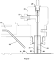
- Figure 1 is a sectional side view of a probe arm 1 of the apparatus according to the invention, with a probe head arranged in a measurement position.
- the probe head comprises a base 20 fixed to the probe arm 1, a capillary tube 21 that is preferably made of a dielectric material, most preferably glass, a first electric contact 24 arranged at least partially within the capillary tube 21 and preferably formed by a metallic wire, pneumatic control means 23, e.g. a fluid connection for selectively producing partial vacuum or ambient pressure within the capillary tube 21 for drawing up a mercury into the capillary tube 21, holding it, and releasing it.
- pneumatic control means 23 e.g. a fluid connection for selectively producing partial vacuum or ambient pressure within the capillary tube 21 for drawing up a mercury into the capillary tube 21, holding it, and releasing it.
- a mercury column M is arranged within the capillary tube 21 so that the bottom surface of the mercury column M is in contact with the top surface of a sample, i.e., a wafer W.
- the capillary tube 21 preferably comprises a flat and smooth bottom surface that is suitable for establishing a sealing contact with a smooth and flat surface of the wafer W.
- the first electric contact 24 is in contact with the mercury column M, preferably by penetrating into it. For the correct operation of the equipment a sufficiently high mercury column M has to be drawn up the capillary for providing electric contact between the first electrical contact 24 and the mercury column M.
- the inner diameter of the capillary tube 21 is 1.7 mm
- the height for the mercury column is about 10-15 mm and thus the mass of the mercury within the probe head is less than 0.5 gram.
- the wafer W is arranged on a wafer holder 3 that is preferably formed by a chuck.
- the wafer holder 3 may have vacuum grooves for holding a bowed wafer flat against the surface of the wafer holder 3.
- the wafer holder 3 or at least a part or preferably the whole of its top surface is preferably made of an electrically conducting material and thus when a wafer W is arranged on the wafer holder 3, an electrical connection is established between a bottom surface of the wafer W and the top surface of the wafer holder 3.
- the capillary tube 21 is fixed to the probe head by metallic sleeve 22 that also provides electric shielding against electric noise from outside.
- the apparatus comprises positioning means for changing the relative position of the probe head and the wafer holder 3.
- the positioning means (not shown in the Figures) must have three degrees of freedom regarding the relative movement of the probe head relative to the wafer holder 3.
- the positioning means may include at least one vertical positioning means and at least two of one or two horizontal positioning means and one or two rotational positioning means with vertical axes. This way the vertical distance between the probe head and the wafer holder 3 may be changed and that the probe head may be positioned above any portion of the surface of the wafer holder 3 and at least one position that is not above the wafer holder 3. This may be achieved in any manner known to a person skilled in the art, e.g.
- the wafer holder 3 and/or the probe arm 1 may be rotated around two different vertical axes.
- the probe arm 1 comprises a gas flow channel 11 and a gas pipe 12 for blowing an inert gas to a measurement site for removing particles from the surface of the wafer W in order to reduce contamination of the mercury and thus prolong the lifetime of each load of mercury.
- the apparatus according to the invention further comprises an electrical measurement means (not shown in the Figures), having two terminals.
- Said electrical measurement means is suitable for providing an electrical voltage or electrical current between its terminals.
- a first terminal of the electrical measurement means is connected to an electrical terminal 25 of the probe head.
- Said electrical terminal 25 is electrically connected to the first electrical contact means 24, which is electrically connected to the mercury column M, which contacts the top surface of the wafer W.
- a second terminal of the electrical measurement means is electrically connected to the wafer holder 3 and through the wafer holder 3 to a bottom surface of said wafer W.
- the electrical measurement means can measure the current-voltage characteristic, i.e. resistance, of the wafer or by producing one of an AC voltage and an AC current between its terminals, and measuring the other one of the AC voltage and the AC current, the measurement means can measure the capacitance-voltage characteristic of the wafer W.
- a partial vacuum of at least about 5-15 Hgmm below the ambient pressure is created via the fluid connection so as to raise the mercury column M from the surface of the wafer W.
- a very slight misalignment between the bottom surface of the capillary tube 21 and the top surface of the wafer W which provides a gap that is large enough to allow air to enter to and escape from the space below the mercury column M, but small enough to prevent mercury from escaping when it is not held by pressure difference between the space above it and the surroundings.
- the apparatus according to the invention further comprises a control unit (not shown), that is in operating connection with the pneumatic control means 23, the positioning means and the measurement means, especially to control the partial vacuum provided by the pneumatic control means, to control the position of the probe head via the positioning means and to control the voltage supplied by the measurement means.
- the control unit is suitable to receive and process measurement results of the measurement means and to control the operation of at least the pneumatic control means on the basis of said measurement results, especially during a mercury change operation.
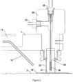
- Figure 2 shows the probe arm 1 and the probe head of the apparatus according to the invention in a stage preceding and following the measurement, when the mercury column M is held by partial vacuum from above.
- the probe head with the probe arm 1 may be raised (or the wafer lowered) and then relative horizontal and/or rotational movement of the probe head and the wafer may be effected by the positioning means so as to select a different measurement site.
- the probe head is lowered onto the surface of the wafer W so that the capillary tube 21 contacts the top surface of the wafer W, the partial vacuum holding the mercury is released and the space above the mercury column M is pressurised and thus the mercury column M is lowered so as to contact the top surface of the wafer W.
- FIG. 3 illustrates the apparatus according to the invention during a mercury change operation.
- the apparatus according to the invention performs a mercury change operation, i.e. it refreshes the mercury held in the capillary tube. This is performed by releasing the partial vacuum holding the mercury column M and letting the mercury fall into a container, and then drawing up a new column of mercury.
- the release of the used mercury and drawing up of a new column may be performed by using the same container to the same effect as the prior art solutions, resulting the mere dilution of the contamination.
- two different containers are provided: a clean mercury container 41 for storing clean mercury and a contaminated mercury container 42 for storing used mercury.
- Figure 3 shows the first stage of mercury change operation, i.e. when the used mercury (not shown) is released into the contaminated mercury container 42.
- the contaminated mercury container 42 is preferably arranged within the clean mercury container 41 so that the bottom of the contaminated mercury container 42 rests on the surface of the clean mercury thus ensuring that the hydrostatic pressure on the bottom of the clean mercury container 41 stays the same after any number of mercury change operations thus facilitating drawing up of a new mercury column of the same volume each time.
- the clean mercury container 41 and the contaminated mercury container 42 are covered by a cover plate 43 that is preferably secured onto the clean mercury container 41 to limit the escape of mercury vapor during a mercury change operation.
- a lid 5 is arranged at a top portion of the cover plate 43. Said lid is open during a mercury change operation, and otherwise the lid 5 is closed above cover plate 43 to completely prevent escape of mercury vapor.
- the lid 5 is preferably biased toward its closed position so that it stays closed without deliberate operation for opening it.
- the clean mercury container 41, the contaminated mercury container 42, the cover plate 43 and the lid 5 together form a mercury containment unit that safely stores the mercury and provides the possibility for the apparatus to replace the mercury content used for measurements at any arbitrary time for a completely clean mercury load.
- the cover plate 43 comprises a first through-hole, i.e. a dumping hole 431 above the contaminated mercury container 42 to allow dropping the used mercury from the capillary tube 21 directly into the contaminated mercury container 42.
- said first stage of mercury change operation is performed by bringing the capillary tube into contact with the cover plate 43 so that the hole of the capillary tube is situated above the dumping hole 431 of the cover plate 43.
- the cover plate 43 has a funnel shaped indentation 433 around the top side of the dumping hole 431 that facilitates safe dumping of used mercury by providing a slanted surface that guides any mercury droplets (possibly created by the splashing down of the dumped mercury) into the contaminated mercury container 42.
- the cover plate 43 preferably further comprises a first pressure relief hole 432 separate from the dumping hole 431 and preferably smaller than the dumping hole 431 to allow some air to escape the contaminated mercury container 42 when used mercury is dumped into it, but to also restrict flow of gases between the inside and outside of the mercury containment unit to limit the escape of mercury vapor.
- the first pressure relief hole 432 facilitates the dumping, as the downward movement of the mercury from the capillary tube 21 would cause a pressure increase in the contaminated mercury container 42, which in turn would slow down the movement of mercury or could even prevent some of the mercury from exiting the capillary tube 21.
- the cover plate optionally further comprises a first rim 434 projecting upward from a top surface of the cover plate 43 and surrounding top ends of both the dumping hole 431 and of the first pressure relief hole 432 in order to prevent any mercury droplets that escaped from rolling away on the surface of the cover plate 43.
- Figure 4 shows a preferred embodiment of the invention during the second stage of a preferred variant of the mercury change operation, namely during drawing up a new mercury column from the clean mercury container 41.
- the capillary tube 21 is arranged above a second through-hole, i.e. a draw hole 435 of the cover plate 43.
- the cover plate preferably has a draw tube 436 reaching down to the bottom of the clean mercury container and thus clean mercury can be drawn through the draw tube and through the draw hole 435 even when the level of mercury is low.
- a sealing element 437 is arranged around the top end of the draw hole 435 so as to facilitate fluidic sealing between the capillary tube 21 and the draw hole 435 so that the partial vacuum provided in the capillary tube 21 does not draw in air from the sides.
- Said sealing element 437 is preferably formed of an elastic material.
- the cover plate 43 preferably further comprises a second pressure relief hole 438 for allowing ambient fluid, e.g. air to enter the clean mercury container when mercury is being drawn up therefrom. This facilitates drawing up mercury by providing a constant pressure equal to the ambient pressure, i.e. an overpressure relative to the partial vacuum within the capillary tube 21.
- This overpressure may be provided by other means, such as by a pressurized gas cartridge fluidically connected to the clean mercury container 41, or by a spring-loaded or weighted cover that exerts pressure on the mercury.
- the second pressure relief hole 438 provides pressure equal to ambient pressure, while the weight of the contaminated mercury container 42 and the contaminated mercury within exert pressure on the clean mercury.
- the contaminated mercury container may be spring-loaded to exert a larger pressure on the clean mercury underneath.
- the second pressure relief hole 438 is preferably smaller than the draw hole 435 to limit the escape of mercury vapor from the mercury containment unit.
- the cover plate optionally further comprises a second rim 439 projecting upward from a top surface of the cover plate 43 and surrounding top ends of both the draw hole 431 and of the second pressure relief hole 438 in order to prevent any mercury droplets that escaped from rolling away on the surface of the cover plate 43.
- Figure 5 shows a yet further preferred embodiment, wherein the apparatus comprises a parking station 6 having a flat top surface and formed of material that is resistant to mercury, i.e., which does not enter into a chemical reaction with mercury, does not form amalgam or alloy with mercury, and cannot be penetrated by mercury, i.e. it is not porous.
- a material is for example silicon-dioxide and thus the parking station 6 may be formed by a piece of thermally oxidized Si wafer.
- Figure shows the probe head in a parking position, wherein the capillary tube 21 abuts on the top surface of the parking station in a fluidically sealing manner and the mercury column M is set down on the surface of the parking station, i.e. the partial vacuum holding it is released.
- the parking station 6 preferably comprises a self-aligning mechanism 61 supporting the flat surface of the parking station 6.
- the self-aligning mechanism 61 facilitates establishing the sealing contact between the parking station 6 and the capillary tube 21 by slight adjustment of the tilt of the parking station 6 when contacted by the capillary tube 21.
- the self-aligning mechanism 61 may be formed by a block of elastic material, which is compressed by the pressure exerted by the capillary tube 21 and ensures the abutment of the top surface of the parking station onto the bottom surface of the capillary tube 21.
- Figure 5 shows an exemplary embodiment, wherein the parking station 6 is located on the top of the lid 5.
- the positioning means is already capable of reaching the top of the mercury containers and the parking station 6 does not occupy another space in the apparatus.
- the parking station may be arranged any other location within the apparatus that is it is accessible by the probe head.
- the lid 5 is provided with a spring 51 that biases the lid 5 toward its closed position, so that in an unpowered state, and even when the mercury containment unit is removed from the apparatus according to the invention, the lid 5 stays firmly closed to prevent evaporation and accidental spilling of mercury contained within.
- the lid 5 is preferably also provided with an actuator 52 for opening and closing the lid 5 during operation.
- the actuator 52 may operate for example on hydraulic, electro-mechanic or pneumatic principle, preferably it is pneumatic.
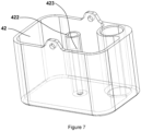
- a central portion of the contaminated mercury container 42 is preferably provided with a vertical guiding sleeve 422.
- a guiding rod 430 of the cover plate 43 may enter the guiding sleeve 422 to restrict the movement of the contaminated mercury container 42 so that it can move only vertically.
- a compression spring 424 may be arranged within the guiding sleeve 422 and around the guiding rod 430 so as to push the contaminated mercury container 42 down when the mercury containment unit is assembled.
- the guiding sleeve 422 may be provided with a suitable abutment surface, e.g. a flange or a shoulder 423 for the spring 424 to sit on.
- Figure 6 shows an exploded view of a particularly preferred embodiment of a mercury containment unit of the apparatus according to the invention, wherein the clean mercury container 41 is a receptacle that is open at its top side and closed from its sides and bottom, the contaminated mercury container 42 is formed as a bucket, having a closed bottom and closed side walls and an open top, furthermore the contaminated mercury container 42 and the clean mercury container 41 are sized so that the contaminated mercury container 42 fits into the clean mercury container 41.
- the contaminated mercury container 42 is provided with a handle 421 that may be raised and may be grabbed by either hand or tweezers and thus the contaminated mercury container 42 can be more easily removed from and placed into the clean mercury container 41.
- the contaminated mercury container 42 is formed and sized so as to allow the draw tube 436 of the cover plate 43 to reach the bottom of the clean mercury container 41. This may be achieved for example by making a horizonal dimension of the contaminated mercury container 42 smaller than that of the clean mercury container 41 by the amount needed to fit the draw tube 436 or by omitting a corner portion of the contaminated mercury container 42. Alternatively, this may be also achieved by providing a through-hole in the contaminated mercury container 42 that extends vertically through the contaminated mercury container 42, as shown in the Figure.
- Figure 6 also shows an exemplary arrangement of the first rim 434 and the second rim 439.
- the first rim 434 surrounds the dumping hole 431 and the first pressure relief hole 432
- the second rim 439 surrounds the draw hole 435 and the second pressure relief hole 438.
- the first rim 434 and the second rim 439 may have a common section or alternatively they may be formed as a single rim that surrounds all of the dumping hole 431, the draw hole 435, the first pressure relief hole 432 and the second pressure relief hole 438.
- Figure 7 is a detailed view of an exemplary embodiment of the contaminated mercury container 42 with the hidden lines displayed as dashed lines so that details of the guiding sleeve 422 with the shoulder 423 are more visible.
- the measuring method according to the invention comprises the well known steps of bringing a capillary tube 21 that contains a mercury column M into contact with a top surface of the wafer W that is arranged on a wafer holder 3, lowering the mercury column M so as to form an electric contact between the mercury column M and the top surface of the wafer W, causing electric current to flow between the mercury column M and the wafer holder 3 through said wafer W, measuring the electric response of said wafer W.
- the method according to the invention further comprises the steps of checking whether a trigger condition is fulfilled and if the trigger condition is fulfilled, the mercury column M is replaced from a clean mercury container 41.
- Said trigger condition may be one or more of a manual trigger by a user, a trigger from a manufacturing control system, a counter that counts the amount of measurements carried out reaching a predetermined threshold.
- Said threshold may be preset according to the cleanliness of the environment. For example, in an industrial cleanroom of the ISO 5 class according to standard ISO 14644-1, the threshold value may be set as high as 50000, i.e. up to fifty thousand measurements may be carried out with the same mercury column. However, in an R&D setting, where the environment is less clean, the threshold value may be less than 5000, i.e. only a few thousand measurements may be performed with the same mercury column.
- the amount and type of contamination on the wafers themselves is also a factor to be considered. For example, SiC wafers that usually have more particulate contamination on their surface tend to contaminate the mercury column in less measurement cycles.
- replacing the mercury column comprises opening a lid 5 that hermetically seals said clean mercury container 41, dumping the mercury column M, drawing up a new mercury column M from the clean mercury container 41 and closing said lid 5.
- Replacing the mercury column M may be performed by dumping it into a larger container containing a larger amount of mercury, and drawing up a new mercury column from the same container. This results in dilution of the contaminants within the larger mercury content and gradually lowers the repeatability of measurements, as each new mercury column will have a progressively increasing contamination from the beginning.
- the replacement of the mercury column M in the method according to the invention is performed by dumping the used mercury column into a contaminated mercury container 42 and then drawing a new mercury column from a clean mercury container 41 different from the used mercury container. This way, upon replacement of the mercury column M, the starting composition of the mercury column M is always the same and thus the repeatability of the measurements is ensured until the clean mercury container 41 runs out of mercury.
- the method according to the invention preferably further comprises returning the probe head into a stand-by position, wherein the capillary tube 21 is placed down onto a flat surface of a parking station 6 and the mercury column M is lowered down to contact said flat surface.
- Returning to said stand-by position is not necessary between each measurement of the same wafer, but it is advantageous when a measurement is not expected for a longer time period.
- the stand-by mode may be engaged when the apparatus is turned off or put into a sleeping mode, or after finishing the measurement of a set of wafers or possibly when measurements of a single wafer are finished.
- drawing up the mercury column M is performed while providing an AC voltage on the first terminal of the electrical measurement means that is connected to the first electrical contact 24 and measuring the capacitance of said first electrical contact 24.
- the first electrical contact has distinctly different capacitance values in a first state without contacting mercury and in a second state with contacting mercury. This difference is even larger in a preferred embodiment, wherein the clean mercury container 41 is made of an electrically insulating material and is placed in a metallic holder that is connected to ground potential, or more preferably to the second terminal of the electrical measurement means.
- the drawing is continued at least until a sharp increase in the measured capacitance is detected, that indicates that the mercury column M contacts the bottom of the first electrical contact 24. More preferably, the drawing is continued for a predetermined time after said increase is detected, in order to ensure that a mercury column of sufficient height will remain in the capillary tube 21 after lifting the capillary tube 21.
- said predetermined time is preferably selected so that an additional height by which mercury is drawn up during said time is about as large as said range and thus this additional height may ensure that the mercury column M remaining within the capillary tube 21 will be sufficient independently from the location of separation within said range.
- the partial vacuum provided in the capillary tube 21 has a draw vacuum value for drawing up mercury from the clean mercury container and a hold vacuum value for holding the mercury column M.
- the hold vacuum for holding a mercury column M with a height of 5-15 mm is negative 5-15 Hgmm relative to ambient pressure.
- Drawing up mercury form the clean mercury container 41 requires a larger pressure difference that has to be able to lift and hold the column of mercury inside the draw tube 436 in addition to the mercury in the capillary tube 21, thus the draw vacuum is stronger than the hold vacuum, e.g. the draw vacuum may be about 50-70 Hgmm. Accordingly, when a sufficient mercury height is reached, i.e. when the drawing is deemed to be finished, the capillary tube 21 is lifted off the sealing element 437 and - preferably at the same time - the partial vacuum provided in the capillary tube 21 is set to the hold vacuum value.
- orientations, directions and relative locations or movement of different components are to be understood as orientations, directions and relative locations as shown in the Figures, which also correspond to the actual intended arrangement of the relevant parts in a properly installed apparatus according to the invention.
Landscapes
- Physics & Mathematics (AREA)
- General Physics & Mathematics (AREA)
- Testing Or Measuring Of Semiconductors Or The Like (AREA)
- Measuring Leads Or Probes (AREA)
- Testing Of Individual Semiconductor Devices (AREA)
Abstract
Description
- This invention relates to a method and apparatus for measuring the electrical properties of a semiconductor wafer using a mercury column as one of the contacts, wherein said method and apparatus improves safety and reduces maintenance needs.
- The use of a mercury column as a non-invasive contact for measuring of the electrical properties of a semiconductor wafers is well known in the art. However, mercury is highly toxic, and presents both health risks and environmental pollution risks, therefore its handling is dangerous and requires specially trained personnel. During measurements, the mercury becomes contaminated via oxidation of the mercury, and by small particles and other contaminants collected from the surface of the wafer. Thus, the amount of mercury used for measurement has to be replaced from time to time.
- There are commercially available apparatuses completely lacking automatic mercury change mechanisms. Such apparatuses are usually only used for research and development purposes, not in an industrial setting where the amount of measurements made and thus the necessary frequency of mercury change would be orders of magnitudes higher. Such apparatuses need their mercury content to be replaced manually, which is usually performed by a trained technician making the apparatus to drop the used mercury into a receptacle, then measuring a predetermined amount of clean mercury onto the surface of a wafer or possibly onto a dedicated surface of the apparatus, positions the probe head above the mercury droplet and triggers picking up the mercury droplet by pneumatic means. Such a manual mercury change operation is time consuming, prone to manual errors, dangerous, and requires specially trained personnel. There are several attempts known in the prior art that intend to make the mercury change operation automatic, faster and safer.
-
U.S. patent No. 4,587,484 describes an apparatus for measuring the electrical properties of a semiconductor wafer through a mercury column. The wafer is contacted by a capillary from the top and mercury is sucked from a reservoir into the capillary by vacuum. Imperfection of the sealing between the wafer and the capillary may lead to spilling a significant amount of mercury. -
U.S. patent No. 7,253,649 describes a similar arrangement for measuring the electrical properties of a wafer, with the wafer being contacted from below by the mercury column. This arrangement reduces the amount of mercury that is spilled upon sealing failure, but the large amount of mercury to be held in the reservoir that is necessary for reaching the sample through relatively long tubes still possess significant danger in the event of failure of the pneumatic system. - Japan publication pamphlet no.
JP6044521 - All of the aforementioned devices have a relatively large mercury reservoir, typically of a volume of 1-2 cm3, that is in fluid communication with the capillary tube and thus present the danger of spilling a large amount of mercury in case of a seal failure or a fault of the pneumatic system.
- During measurements, the mercury becomes contaminated via oxidation of the mercury, and by small particles and other contaminants collected from the surface of the wafer. This results in the need of periodic replacement of the mercury content of the device, which is performed by manually replacing the whole unit comprising the mercury reservoir.
- While the danger of spilling a large amount of mercury could be reduced in the aforementioned systems by reducing the amount of mercury held in the reservoir, this would come at the cost of reducing the time between necessary replacements of the mercury containing unit, because the same amount of contamination introduced into a smaller amount of mercury would result in reduced measurement accuracy sooner. Depending on the cleanliness of the surroundings of the apparatus and on the amount of measurements carried out, replacement of the mercury in devices having a supply of 1-2 cm3 may be necessary as often as a couple of weeks.
- In light of the foregoing, the object of the present invention is to eliminate or at least ameliorate the drawbacks of the prior art solutions. More specifically, the object of the present invention is to provide a mercury probe apparatus for measuring the electrical properties of a semiconductor wafer with improved safety, wherein the danger of mercury spill is reduced without increasing the frequency of maintenance. A further object of the present invention is to provide a measurement apparatus with improved safety, wherein the apparatus is able to use fresh mercury for measurements without manual servicing. A yet further objective of the present invention is to provide a measurement apparatus with improved safety, wherein the evaporation of mercury and the emission of mercury vapor is practically eliminated.
- The above objectives have been achieved by developing the apparatus according to
claim 1. Preferred exemplary embodiments of the apparatus according to the invention are set out in claims 2-9. The above objectives have been achieved further by developing the method according to claim 10. Preferred variants of the method are set out in claims 11-14. - In what follows, preferred embodiments of the apparatus according to the invention and the operation thereof are described in detail with reference to the attached drawing, where
-
Figure 1 is a sectional side view of the probe arm with the probe head in the measurement position, during measurement; -
Figure 2 is a sectional side view of the probe arm with the probe head in the measurement position, before and after measurement; -
Figure 3 is a sectional side view of the probe arm with the probe head in a first mercury change position; -
Figure 4 is a sectional side view of the probe arm with the probe head in a second mercury change position; -
Figure 5 is a sectional side view of the probe arm with the probe head in a parking position; -
Figure 6 is an exploded view of the main components of the first and second mercury containers; -
Figure 7 is a detailed view of an exemplary embodiment of the contaminated mercury container. - The same reference numbers on different Figures indicate the same parts.
-
Figure 1 is a sectional side view of aprobe arm 1 of the apparatus according to the invention, with a probe head arranged in a measurement position. The probe head comprises abase 20 fixed to theprobe arm 1, acapillary tube 21 that is preferably made of a dielectric material, most preferably glass, a firstelectric contact 24 arranged at least partially within thecapillary tube 21 and preferably formed by a metallic wire, pneumatic control means 23, e.g. a fluid connection for selectively producing partial vacuum or ambient pressure within thecapillary tube 21 for drawing up a mercury into thecapillary tube 21, holding it, and releasing it. During measurement - as shown inFigure 1 - a mercury column M is arranged within thecapillary tube 21 so that the bottom surface of the mercury column M is in contact with the top surface of a sample, i.e., a wafer W. Thecapillary tube 21 preferably comprises a flat and smooth bottom surface that is suitable for establishing a sealing contact with a smooth and flat surface of the wafer W. The firstelectric contact 24 is in contact with the mercury column M, preferably by penetrating into it. For the correct operation of the equipment a sufficiently high mercury column M has to be drawn up the capillary for providing electric contact between the firstelectrical contact 24 and the mercury column M. As shown in the Figure, during measurement, only the mercury that is present in thecapillary tube 21 is moved by the fluid pressure supplied through the fluid connection, and accordingly, only this very small amount of mercury could be potentially spilled if the contact between thecapillary tube 21 and the wafer W is not sealing well enough. According to a particularly preferred exemplary embodiment, the inner diameter of thecapillary tube 21 is 1.7 mm, the height for the mercury column is about 10-15 mm and thus the mass of the mercury within the probe head is less than 0.5 gram. - The wafer W is arranged on a
wafer holder 3 that is preferably formed by a chuck. Thewafer holder 3 may have vacuum grooves for holding a bowed wafer flat against the surface of thewafer holder 3. Thewafer holder 3 or at least a part or preferably the whole of its top surface is preferably made of an electrically conducting material and thus when a wafer W is arranged on thewafer holder 3, an electrical connection is established between a bottom surface of the wafer W and the top surface of thewafer holder 3. - In the exemplary embodiment shown in
Figure 1 , thecapillary tube 21 is fixed to the probe head bymetallic sleeve 22 that also provides electric shielding against electric noise from outside. - The apparatus comprises positioning means for changing the relative position of the probe head and the
wafer holder 3. The positioning means (not shown in the Figures) must have three degrees of freedom regarding the relative movement of the probe head relative to thewafer holder 3. Accordingly, the positioning means may include at least one vertical positioning means and at least two of one or two horizontal positioning means and one or two rotational positioning means with vertical axes. This way the vertical distance between the probe head and thewafer holder 3 may be changed and that the probe head may be positioned above any portion of the surface of thewafer holder 3 and at least one position that is not above thewafer holder 3. This may be achieved in any manner known to a person skilled in the art, e.g. using an XYZ stage for linear movement of the wafer holder or the probe head or using two separate XYZ positioning means for moving each. Alternatively or additionally to the horizontal translation movement(s), thewafer holder 3 and/or theprobe arm 1 may be rotated around two different vertical axes. - According to the exemplary embodiment shown in
Figure 1 , theprobe arm 1 comprises agas flow channel 11 and agas pipe 12 for blowing an inert gas to a measurement site for removing particles from the surface of the wafer W in order to reduce contamination of the mercury and thus prolong the lifetime of each load of mercury. - Measurement is carried out in the position of the probe head shown in
Figure 1 , i.e. when thecapillary tube 21 and the mercury column M contacts the surface of the wafer W. The apparatus according to the invention further comprises an electrical measurement means (not shown in the Figures), having two terminals. Said electrical measurement means is suitable for providing an electrical voltage or electrical current between its terminals. A first terminal of the electrical measurement means is connected to anelectrical terminal 25 of the probe head. Saidelectrical terminal 25 is electrically connected to the first electrical contact means 24, which is electrically connected to the mercury column M, which contacts the top surface of the wafer W. A second terminal of the electrical measurement means is electrically connected to thewafer holder 3 and through thewafer holder 3 to a bottom surface of said wafer W. By producing one of a DC voltage and a DC current between its terminals, and measuring the other one of the DC voltage and the DC current, the electrical measurement means can measure the current-voltage characteristic, i.e. resistance, of the wafer or by producing one of an AC voltage and an AC current between its terminals, and measuring the other one of the AC voltage and the AC current, the measurement means can measure the capacitance-voltage characteristic of the wafer W. - After finishing a measurement, a partial vacuum of at least about 5-15 Hgmm below the ambient pressure is created via the fluid connection so as to raise the mercury column M from the surface of the wafer W. There is a very slight misalignment between the bottom surface of the
capillary tube 21 and the top surface of the wafer W, which provides a gap that is large enough to allow air to enter to and escape from the space below the mercury column M, but small enough to prevent mercury from escaping when it is not held by pressure difference between the space above it and the surroundings. - The apparatus according to the invention further comprises a control unit (not shown), that is in operating connection with the pneumatic control means 23, the positioning means and the measurement means, especially to control the partial vacuum provided by the pneumatic control means, to control the position of the probe head via the positioning means and to control the voltage supplied by the measurement means. According to a preferred embodiment, the control unit is suitable to receive and process measurement results of the measurement means and to control the operation of at least the pneumatic control means on the basis of said measurement results, especially during a mercury change operation.
-
Figure 2 shows theprobe arm 1 and the probe head of the apparatus according to the invention in a stage preceding and following the measurement, when the mercury column M is held by partial vacuum from above. The probe head with theprobe arm 1 may be raised (or the wafer lowered) and then relative horizontal and/or rotational movement of the probe head and the wafer may be effected by the positioning means so as to select a different measurement site. On the new measurement site, the probe head is lowered onto the surface of the wafer W so that thecapillary tube 21 contacts the top surface of the wafer W, the partial vacuum holding the mercury is released and the space above the mercury column M is pressurised and thus the mercury column M is lowered so as to contact the top surface of the wafer W. -
Figure 3 illustrates the apparatus according to the invention during a mercury change operation. Upon the fulfilment of a trigger condition, the apparatus according to the invention performs a mercury change operation, i.e. it refreshes the mercury held in the capillary tube. This is performed by releasing the partial vacuum holding the mercury column M and letting the mercury fall into a container, and then drawing up a new column of mercury. The release of the used mercury and drawing up of a new column may be performed by using the same container to the same effect as the prior art solutions, resulting the mere dilution of the contamination. However, in the particularly preferred exemplary embodiment shown inFigure 3 , two different containers are provided: aclean mercury container 41 for storing clean mercury and a contaminatedmercury container 42 for storing used mercury.Figure 3 shows the first stage of mercury change operation, i.e. when the used mercury (not shown) is released into the contaminatedmercury container 42. The contaminatedmercury container 42 is preferably arranged within theclean mercury container 41 so that the bottom of the contaminatedmercury container 42 rests on the surface of the clean mercury thus ensuring that the hydrostatic pressure on the bottom of theclean mercury container 41 stays the same after any number of mercury change operations thus facilitating drawing up of a new mercury column of the same volume each time. - The
clean mercury container 41 and the contaminatedmercury container 42 are covered by acover plate 43 that is preferably secured onto theclean mercury container 41 to limit the escape of mercury vapor during a mercury change operation. Preferably alid 5 is arranged at a top portion of thecover plate 43. Said lid is open during a mercury change operation, and otherwise thelid 5 is closed abovecover plate 43 to completely prevent escape of mercury vapor. Thelid 5 is preferably biased toward its closed position so that it stays closed without deliberate operation for opening it. Theclean mercury container 41, the contaminatedmercury container 42, thecover plate 43 and thelid 5 together form a mercury containment unit that safely stores the mercury and provides the possibility for the apparatus to replace the mercury content used for measurements at any arbitrary time for a completely clean mercury load. Thecover plate 43 comprises a first through-hole, i.e. a dumpinghole 431 above the contaminatedmercury container 42 to allow dropping the used mercury from thecapillary tube 21 directly into the contaminatedmercury container 42. - Preferably, said first stage of mercury change operation is performed by bringing the capillary tube into contact with the
cover plate 43 so that the hole of the capillary tube is situated above the dumpinghole 431 of thecover plate 43. According to a further preferred embodiment, thecover plate 43 has a funnel shapedindentation 433 around the top side of the dumpinghole 431 that facilitates safe dumping of used mercury by providing a slanted surface that guides any mercury droplets (possibly created by the splashing down of the dumped mercury) into the contaminatedmercury container 42. - The
cover plate 43 preferably further comprises a firstpressure relief hole 432 separate from the dumpinghole 431 and preferably smaller than the dumpinghole 431 to allow some air to escape the contaminatedmercury container 42 when used mercury is dumped into it, but to also restrict flow of gases between the inside and outside of the mercury containment unit to limit the escape of mercury vapor. The firstpressure relief hole 432 facilitates the dumping, as the downward movement of the mercury from thecapillary tube 21 would cause a pressure increase in the contaminatedmercury container 42, which in turn would slow down the movement of mercury or could even prevent some of the mercury from exiting thecapillary tube 21. - The cover plate optionally further comprises a
first rim 434 projecting upward from a top surface of thecover plate 43 and surrounding top ends of both the dumpinghole 431 and of the firstpressure relief hole 432 in order to prevent any mercury droplets that escaped from rolling away on the surface of thecover plate 43. -
Figure 4 shows a preferred embodiment of the invention during the second stage of a preferred variant of the mercury change operation, namely during drawing up a new mercury column from theclean mercury container 41. In the figure, thecapillary tube 21 is arranged above a second through-hole, i.e. adraw hole 435 of thecover plate 43. The cover plate preferably has adraw tube 436 reaching down to the bottom of the clean mercury container and thus clean mercury can be drawn through the draw tube and through thedraw hole 435 even when the level of mercury is low. Preferably, a sealingelement 437 is arranged around the top end of thedraw hole 435 so as to facilitate fluidic sealing between thecapillary tube 21 and thedraw hole 435 so that the partial vacuum provided in thecapillary tube 21 does not draw in air from the sides. Said sealingelement 437 is preferably formed of an elastic material. Thecover plate 43 preferably further comprises a secondpressure relief hole 438 for allowing ambient fluid, e.g. air to enter the clean mercury container when mercury is being drawn up therefrom. This facilitates drawing up mercury by providing a constant pressure equal to the ambient pressure, i.e. an overpressure relative to the partial vacuum within thecapillary tube 21. This overpressure may be provided by other means, such as by a pressurized gas cartridge fluidically connected to theclean mercury container 41, or by a spring-loaded or weighted cover that exerts pressure on the mercury. These measures may be employed together: the secondpressure relief hole 438 provides pressure equal to ambient pressure, while the weight of the contaminatedmercury container 42 and the contaminated mercury within exert pressure on the clean mercury. Furthermore, the contaminated mercury container may be spring-loaded to exert a larger pressure on the clean mercury underneath. The secondpressure relief hole 438 is preferably smaller than thedraw hole 435 to limit the escape of mercury vapor from the mercury containment unit. - The cover plate optionally further comprises a
second rim 439 projecting upward from a top surface of thecover plate 43 and surrounding top ends of both thedraw hole 431 and of the secondpressure relief hole 438 in order to prevent any mercury droplets that escaped from rolling away on the surface of thecover plate 43. -
Figure 5 shows a yet further preferred embodiment, wherein the apparatus comprises aparking station 6 having a flat top surface and formed of material that is resistant to mercury, i.e., which does not enter into a chemical reaction with mercury, does not form amalgam or alloy with mercury, and cannot be penetrated by mercury, i.e. it is not porous. Such a material is for example silicon-dioxide and thus theparking station 6 may be formed by a piece of thermally oxidized Si wafer. Figure shows the probe head in a parking position, wherein thecapillary tube 21 abuts on the top surface of the parking station in a fluidically sealing manner and the mercury column M is set down on the surface of the parking station, i.e. the partial vacuum holding it is released. This is a stand-by position of the apparatus according to the invention, wherein the mercury column M is sealed from ambient air and thus its oxidation is prevented prolonging its lifetime. At the same time, evaporation of mercury is also prevented in the stand-by position, thus improving safety. - The
parking station 6 preferably comprises a self-aligningmechanism 61 supporting the flat surface of theparking station 6. The self-aligningmechanism 61 facilitates establishing the sealing contact between theparking station 6 and thecapillary tube 21 by slight adjustment of the tilt of theparking station 6 when contacted by thecapillary tube 21. For example, the self-aligningmechanism 61 may be formed by a block of elastic material, which is compressed by the pressure exerted by thecapillary tube 21 and ensures the abutment of the top surface of the parking station onto the bottom surface of thecapillary tube 21.Figure 5 shows an exemplary embodiment, wherein theparking station 6 is located on the top of thelid 5. This is merely a convenient placement, because the positioning means is already capable of reaching the top of the mercury containers and theparking station 6 does not occupy another space in the apparatus. Alternatively, the parking station may be arranged any other location within the apparatus that is it is accessible by the probe head. - According to the preferred exemplary embodiment shown in
Figure 5 , thelid 5 is provided with aspring 51 that biases thelid 5 toward its closed position, so that in an unpowered state, and even when the mercury containment unit is removed from the apparatus according to the invention, thelid 5 stays firmly closed to prevent evaporation and accidental spilling of mercury contained within. Thelid 5 is preferably also provided with anactuator 52 for opening and closing thelid 5 during operation. Theactuator 52 may operate for example on hydraulic, electro-mechanic or pneumatic principle, preferably it is pneumatic. - A central portion of the contaminated
mercury container 42 is preferably provided with avertical guiding sleeve 422. A guidingrod 430 of thecover plate 43 may enter the guidingsleeve 422 to restrict the movement of the contaminatedmercury container 42 so that it can move only vertically. Furthermore, acompression spring 424 may be arranged within the guidingsleeve 422 and around the guidingrod 430 so as to push the contaminatedmercury container 42 down when the mercury containment unit is assembled. The guidingsleeve 422 may be provided with a suitable abutment surface, e.g. a flange or ashoulder 423 for thespring 424 to sit on. -
Figure 6 shows an exploded view of a particularly preferred embodiment of a mercury containment unit of the apparatus according to the invention, wherein theclean mercury container 41 is a receptacle that is open at its top side and closed from its sides and bottom, the contaminatedmercury container 42 is formed as a bucket, having a closed bottom and closed side walls and an open top, furthermore the contaminatedmercury container 42 and theclean mercury container 41 are sized so that the contaminatedmercury container 42 fits into theclean mercury container 41. According to the preferred exemplary embodiment shown in the Figure, the contaminatedmercury container 42 is provided with ahandle 421 that may be raised and may be grabbed by either hand or tweezers and thus the contaminatedmercury container 42 can be more easily removed from and placed into theclean mercury container 41. - The contaminated
mercury container 42 is formed and sized so as to allow thedraw tube 436 of thecover plate 43 to reach the bottom of theclean mercury container 41. This may be achieved for example by making a horizonal dimension of the contaminatedmercury container 42 smaller than that of theclean mercury container 41 by the amount needed to fit thedraw tube 436 or by omitting a corner portion of the contaminatedmercury container 42. Alternatively, this may be also achieved by providing a through-hole in the contaminatedmercury container 42 that extends vertically through the contaminatedmercury container 42, as shown in the Figure. -
Figure 6 also shows an exemplary arrangement of thefirst rim 434 and thesecond rim 439. In this embodiment, thefirst rim 434 surrounds the dumpinghole 431 and the firstpressure relief hole 432, and thesecond rim 439 surrounds thedraw hole 435 and the secondpressure relief hole 438. Thefirst rim 434 and thesecond rim 439 may have a common section or alternatively they may be formed as a single rim that surrounds all of the dumpinghole 431, thedraw hole 435, the firstpressure relief hole 432 and the secondpressure relief hole 438. -
Figure 7 is a detailed view of an exemplary embodiment of the contaminatedmercury container 42 with the hidden lines displayed as dashed lines so that details of the guidingsleeve 422 with theshoulder 423 are more visible. - The measuring method according to the invention comprises the well known steps of bringing a
capillary tube 21 that contains a mercury column M into contact with a top surface of the wafer W that is arranged on awafer holder 3, lowering the mercury column M so as to form an electric contact between the mercury column M and the top surface of the wafer W, causing electric current to flow between the mercury column M and thewafer holder 3 through said wafer W, measuring the electric response of said wafer W. The method according to the invention further comprises the steps of checking whether a trigger condition is fulfilled and if the trigger condition is fulfilled, the mercury column M is replaced from aclean mercury container 41. - Said trigger condition may be one or more of a manual trigger by a user, a trigger from a manufacturing control system, a counter that counts the amount of measurements carried out reaching a predetermined threshold. Said threshold may be preset according to the cleanliness of the environment. For example, in an industrial cleanroom of the
ISO 5 class according to standard ISO 14644-1, the threshold value may be set as high as 50000, i.e. up to fifty thousand measurements may be carried out with the same mercury column. However, in an R&D setting, where the environment is less clean, the threshold value may be less than 5000, i.e. only a few thousand measurements may be performed with the same mercury column. The amount and type of contamination on the wafers themselves is also a factor to be considered. For example, SiC wafers that usually have more particulate contamination on their surface tend to contaminate the mercury column in less measurement cycles. - Mercury that is available for replacing the mercury column held in the capillary tube is preferably held in a sealed container, that may be opened and closed by an actuator. Accordingly, replacing the mercury column comprises opening a
lid 5 that hermetically seals saidclean mercury container 41, dumping the mercury column M, drawing up a new mercury column M from theclean mercury container 41 and closing saidlid 5. - Replacing the mercury column M may be performed by dumping it into a larger container containing a larger amount of mercury, and drawing up a new mercury column from the same container. This results in dilution of the contaminants within the larger mercury content and gradually lowers the repeatability of measurements, as each new mercury column will have a progressively increasing contamination from the beginning.
- The replacement of the mercury column M in the method according to the invention is performed by dumping the used mercury column into a contaminated
mercury container 42 and then drawing a new mercury column from aclean mercury container 41 different from the used mercury container. This way, upon replacement of the mercury column M, the starting composition of the mercury column M is always the same and thus the repeatability of the measurements is ensured until theclean mercury container 41 runs out of mercury. - The method according to the invention preferably further comprises returning the probe head into a stand-by position, wherein the
capillary tube 21 is placed down onto a flat surface of aparking station 6 and the mercury column M is lowered down to contact said flat surface. This limits the exposure of mercury to oxygen and thus reduces its oxidation. Returning to said stand-by position is not necessary between each measurement of the same wafer, but it is advantageous when a measurement is not expected for a longer time period. For example, the stand-by mode may be engaged when the apparatus is turned off or put into a sleeping mode, or after finishing the measurement of a set of wafers or possibly when measurements of a single wafer are finished. - According to a further variant of the method according to the invention, drawing up the mercury column M is performed while providing an AC voltage on the first terminal of the electrical measurement means that is connected to the first
electrical contact 24 and measuring the capacitance of said firstelectrical contact 24. The first electrical contact has distinctly different capacitance values in a first state without contacting mercury and in a second state with contacting mercury. This difference is even larger in a preferred embodiment, wherein theclean mercury container 41 is made of an electrically insulating material and is placed in a metallic holder that is connected to ground potential, or more preferably to the second terminal of the electrical measurement means. This way, in the second state, wherein the firstelectrical contact 24 is in contact with a mercury column M that continuously fills thedraw tube 436 and reaches a bottom of theclean mercury container 41, forms a condenser with said metallic holder with theclean mercury container 41 being the isolator therebetween. Preferably, the drawing is continued at least until a sharp increase in the measured capacitance is detected, that indicates that the mercury column M contacts the bottom of the firstelectrical contact 24. More preferably, the drawing is continued for a predetermined time after said increase is detected, in order to ensure that a mercury column of sufficient height will remain in thecapillary tube 21 after lifting thecapillary tube 21. When thecapillary tube 21 is lifted, ambient medium may enter between the sealingelement 437 and thecapillary tube 21 thus the ambient pressure no longer supports the mercury within thedraw tube 436 and thus the mercury column M is separated at a location in the proximity of the bottom of thecapillary tube 21. The separation occurs at a random location within a range. Accordingly, said predetermined time is preferably selected so that an additional height by which mercury is drawn up during said time is about as large as said range and thus this additional height may ensure that the mercury column M remaining within thecapillary tube 21 will be sufficient independently from the location of separation within said range. - The partial vacuum provided in the
capillary tube 21 has a draw vacuum value for drawing up mercury from the clean mercury container and a hold vacuum value for holding the mercury column M. The hold vacuum for holding a mercury column M with a height of 5-15 mm is negative 5-15 Hgmm relative to ambient pressure. Drawing up mercury form theclean mercury container 41 requires a larger pressure difference that has to be able to lift and hold the column of mercury inside thedraw tube 436 in addition to the mercury in thecapillary tube 21, thus the draw vacuum is stronger than the hold vacuum, e.g. the draw vacuum may be about 50-70 Hgmm. Accordingly, when a sufficient mercury height is reached, i.e. when the drawing is deemed to be finished, thecapillary tube 21 is lifted off the sealingelement 437 and - preferably at the same time - the partial vacuum provided in thecapillary tube 21 is set to the hold vacuum value. - Generally, in the framework of the present specification, the terms `up', 'down', 'top', 'bottom', 'vertical', 'horizontal' and other similar expressions regarding orientations, directions and relative locations or movement of different components are to be understood as orientations, directions and relative locations as shown in the Figures, which also correspond to the actual intended arrangement of the relevant parts in a properly installed apparatus according to the invention.
Claims (15)
- An apparatus for measuring electrical properties of a semiconductor wafer (W), said apparatus comprising:a wafer holder (3);a probe head for contacting the top surface of said wafer (W) with a mercury column (M), said probe head including a capillary tube (21) for containing said mercury column (M);a pneumatic control means (23) for applying a partial vacuum or pressure above said mercury column (M) within said capillary tube (21);a probe arm (1) having said probe head affixed thereto;a positioning means for controlling the position of said capillary tube (21) relative to the upper surface of said wafer (W);a measurement means for causing an electrical current to flow through said wafer and for measuring electrical properties of said wafer;a first electrical contact (24) electrically connected to said mercury column (M) and to said measurement means;a second electrical contact electrically connected to said wafer holder (3) and said measurement means;a clean mercury container (41);a control unit in operating connection with the pneumatic control means (23), the positioning means and the measurement means,characterized in thatsaid probe head has at least one measurement position and a first mercury change position, whereinthe capillary tube (21) is separated from the clean mercury container (41) in said at least one measurement position, andthe capillary tube (21) is in fluid communication with the clean mercury container (41) in said first mercury change position.
- The apparatus according to claim 1, characterized in that the clean mercury container (41) comprises a lid (5) for closing and hermetically sealing said clean mercury container (41).
- The apparatus of claim 1, characterized in that the apparatus comprises a contaminated mercury container (42), and the probe head has a second mercury change position, wherein the probe head is in fluid communication with the contaminated mercury container (42) is said second mercury change position.
- The apparatus of claim 3, characterized in that the clean mercury container (41) and the contaminated mercury container (42) are arranged within a single enclosure, with their walls separating their mercury content.
- The apparatus of claim 4, characterized in that the contaminated mercury container (42) is formed as a bucket arranged within the clean mercury container (41) so that a bottom of said contaminated mercury container (42) rests on a top surface of mercury contained within the clean mercury container (41).
- The apparatus of claim 5, characterized in that the contaminated mercury container (42) is pushed down by a cover plate (43) secured on top of the clean mercury container (41) via a spring (424).
- The apparatus of claim 1, characterized in that the apparatus comprises a parking station (6) comprising a flat and smooth surface of a mercury-resistant material, and wherein the probe head has a parking position wherein the capillary tube (21) is placed on the parking station with a bottom surface of the capillary tube (21) abutting on and forming a sealing contact with the top surface of the parking station (6).
- The apparatus of claim 7, characterized in that the parking station (6) is formed by a silicon wafer having a thermally oxidized top surface.
- The apparatus of claim 7, characterized in that the parking station comprises a self-aligning mechanism (61) for adjusting the alignment of the surface of the parking station (6) to that of a bottom surface of the capillary tube (21) that is placed on top of the parking station.
- A method for measurement of electrical properties of a semiconductor wafer (W) that is arranged on a wafer holder (3), said method comprising:- bringing a capillary tube (21) that contains a mercury column (M) into contact with a top surface of the wafer (W);- lowering the mercury column (M) so as to form an electric contact between the mercury column (M) and the top surface of the wafer (W);- applying a voltage between the mercury column (M) and the wafer holder (3) that is in electrical connection with said wafer (W);- performing electrical measurement to determine at least one electric parameter of said wafer (W);characterised in that the method further comprises- checking whether a trigger condition is fulfilled, and- if the trigger condition is fulfilled, the mercury column (M) is replaced from a clean mercury container (41).
- The method according to claim 10, characterized in that replacing the mercury column comprises opening a lid (5) that hermetically seals said clean mercury container (41), dumping the mercury column (M), drawing up a new mercury column (M) from the clean mercury container (41) and closing said lid (5).
- The method according to claim 10, characterized in that replacing the mercury column (M) comprises dumping the mercury column (M) into a contaminated mercury container (42) and drawing a new mercury column (M) from the clean mercury container (41) that is separate from the contaminated mercury container (42).
- The method according to claim 10, characterized in that the method further comprises placing down the capillary tube (21) onto a flat surface of a parking station (6) and lowering the mercury column (M) down to contact said flat surface.
- The method according to claim 10, characterized in that the trigger condition is any one of: a manual trigger by a user, a trigger from a manufacturing control system, a number of electrical measurements carried out since the last mercury change operation reaching a predetermined threshold.
- The method according to claim 10, characterized in that electrical measurement is performed during the replacement of the mercury column (M) to control a height of the mercury column (M) drawn up to the capillary tube (21).
Applications Claiming Priority (1)
| Application Number | Priority Date | Filing Date | Title |
|---|---|---|---|
| HU2300380A HUP2300380A1 (en) | 2023-11-07 | 2023-11-07 | Mercury probe device with improved safety features |
Publications (1)
| Publication Number | Publication Date |
|---|---|
| EP4553506A1 true EP4553506A1 (en) | 2025-05-14 |
Family
ID=93609074
Family Applications (1)
| Application Number | Title | Priority Date | Filing Date |
|---|---|---|---|
| EP24211590.5A Pending EP4553506A1 (en) | 2023-11-07 | 2024-11-07 | Mercury probe apparatus with improved safety |
Country Status (6)
| Country | Link |
|---|---|
| US (1) | US20250147070A1 (en) |
| EP (1) | EP4553506A1 (en) |
| JP (1) | JP2025078093A (en) |
| CN (1) | CN119959585A (en) |
| HU (1) | HUP2300380A1 (en) |
| TW (1) | TW202532857A (en) |
Citations (8)
| Publication number | Priority date | Publication date | Assignee | Title |
|---|---|---|---|---|
| SU1105963A1 (en) * | 1982-02-01 | 1984-07-30 | Предприятие П/Я В-2836 | Mercury probe |
| US4587484A (en) | 1981-01-19 | 1986-05-06 | Msi Electronics Inc. | Mercury probe and method |
| US7253649B1 (en) | 2006-01-31 | 2007-08-07 | Four Dimensions, Inc, | Automatic mercury probe for use with a semiconductor wafer |
| US20070273397A1 (en) * | 2004-08-13 | 2007-11-29 | Shin-Etsu Handotai Co., Ltd. | Apparatus for Evaluating Semiconductor Wafer |
| US20140017826A1 (en) * | 2012-07-10 | 2014-01-16 | Showa Denko K.K. | Semiconductor wafer evaluation method, semiconductor wafer evaluation device, and probe for semiconductor evaluation device |
| JP6044521B2 (en) | 2013-11-19 | 2016-12-14 | 信越半導体株式会社 | Semiconductor wafer characteristic measurement system |
| KR20190002789A (en) * | 2017-06-29 | 2019-01-09 | 한국표준과학연구원 | Insitu Equipment for Measuring Dielectric Properties and Insitu Method for Measuring Dielectric Properties |
| CN115792558A (en) * | 2023-02-08 | 2023-03-14 | 北京科里特科技有限公司 | Capacitance-voltage testing device and capacitance-voltage testing method for semiconductor structure |
-
2023
- 2023-11-07 HU HU2300380A patent/HUP2300380A1/en unknown
-
2024
- 2024-10-21 TW TW113139982A patent/TW202532857A/en unknown
- 2024-11-06 JP JP2024194581A patent/JP2025078093A/en active Pending
- 2024-11-06 US US18/939,399 patent/US20250147070A1/en active Pending
- 2024-11-07 CN CN202411581092.7A patent/CN119959585A/en active Pending
- 2024-11-07 EP EP24211590.5A patent/EP4553506A1/en active Pending
Patent Citations (8)
| Publication number | Priority date | Publication date | Assignee | Title |
|---|---|---|---|---|
| US4587484A (en) | 1981-01-19 | 1986-05-06 | Msi Electronics Inc. | Mercury probe and method |
| SU1105963A1 (en) * | 1982-02-01 | 1984-07-30 | Предприятие П/Я В-2836 | Mercury probe |
| US20070273397A1 (en) * | 2004-08-13 | 2007-11-29 | Shin-Etsu Handotai Co., Ltd. | Apparatus for Evaluating Semiconductor Wafer |
| US7253649B1 (en) | 2006-01-31 | 2007-08-07 | Four Dimensions, Inc, | Automatic mercury probe for use with a semiconductor wafer |
| US20140017826A1 (en) * | 2012-07-10 | 2014-01-16 | Showa Denko K.K. | Semiconductor wafer evaluation method, semiconductor wafer evaluation device, and probe for semiconductor evaluation device |
| JP6044521B2 (en) | 2013-11-19 | 2016-12-14 | 信越半導体株式会社 | Semiconductor wafer characteristic measurement system |
| KR20190002789A (en) * | 2017-06-29 | 2019-01-09 | 한국표준과학연구원 | Insitu Equipment for Measuring Dielectric Properties and Insitu Method for Measuring Dielectric Properties |
| CN115792558A (en) * | 2023-02-08 | 2023-03-14 | 北京科里特科技有限公司 | Capacitance-voltage testing device and capacitance-voltage testing method for semiconductor structure |
Also Published As
| Publication number | Publication date |
|---|---|
| TW202532857A (en) | 2025-08-16 |
| US20250147070A1 (en) | 2025-05-08 |
| JP2025078093A (en) | 2025-05-19 |
| HUP2300380A1 (en) | 2025-05-28 |
| CN119959585A (en) | 2025-05-09 |
Similar Documents
| Publication | Publication Date | Title |
|---|---|---|
| KR100959388B1 (en) | GP unit and door opening and closing device of semiconductor wafer pollutant measuring device | |
| US6199604B1 (en) | Clean box, clean transfer method and apparatus therefor | |
| EP4553506A1 (en) | Mercury probe apparatus with improved safety | |
| KR101691607B1 (en) | Wafer container transferring apparatus with purging function | |
| JPH05136218A (en) | Inspection device | |
| CN109477853A (en) | Pipetting device with a pipette tip detection unit and method for detecting a pipette tip at a pipetting device | |
| JP2007147537A (en) | Probe card transfer assist device and inspection equipment | |
| CN113903688A (en) | Semiconductor process equipment and wafer state monitoring method | |
| HK40125829A (en) | Mercury probe apparatus with improved safety | |
| KR19980024359A (en) | Film thickness measuring device | |
| WO2000042413A1 (en) | Device and method for measuring air permeability | |
| JP2020061535A (en) | Bottom gas purge apparatus, load port apparatus, and bottom gas purge method | |
| US20240142480A1 (en) | Automated system for remote chemical sample collection with safe isolation of sample vessel | |
| JP2869042B2 (en) | Apparatus for storing liquid or pasty products and dispensing a predetermined amount of them | |
| JP4924307B2 (en) | Glass crushing and filling equipment | |
| CN118010947A (en) | Measuring device | |
| TWI639540B (en) | Container storage device | |
| JP2010027810A (en) | Vacuum carrier | |
| CN221680040U (en) | A cigarette lifting mechanism and a cigarette sampler | |
| KR102912362B1 (en) | Lead glass mini-cell for sensitization test of radioactive material | |
| JPH0443900A (en) | Liquid supply device | |
| JP3683556B2 (en) | Solder supply device | |
| KR102868769B1 (en) | Substrate processing apparatus | |
| CN116840106A (en) | Device and method for testing room-temperature surface wettability of gallium-based liquid metal | |
| JPH0582620A (en) | Mechanical interface device |
Legal Events
| Date | Code | Title | Description |
|---|---|---|---|
| PUAI | Public reference made under article 153(3) epc to a published international application that has entered the european phase |
Free format text: ORIGINAL CODE: 0009012 |
|
| STAA | Information on the status of an ep patent application or granted ep patent |
Free format text: STATUS: THE APPLICATION HAS BEEN PUBLISHED |
|
| AK | Designated contracting states |
Kind code of ref document: A1 Designated state(s): AL AT BE BG CH CY CZ DE DK EE ES FI FR GB GR HR HU IE IS IT LI LT LU LV MC ME MK MT NL NO PL PT RO RS SE SI SK SM TR |
|
| STAA | Information on the status of an ep patent application or granted ep patent |
Free format text: STATUS: REQUEST FOR EXAMINATION WAS MADE |
|
| 17P | Request for examination filed |
Effective date: 20250905 |
|
| GRAP | Despatch of communication of intention to grant a patent |
Free format text: ORIGINAL CODE: EPIDOSNIGR1 |
|
| STAA | Information on the status of an ep patent application or granted ep patent |
Free format text: STATUS: GRANT OF PATENT IS INTENDED |
|
| RIC1 | Information provided on ipc code assigned before grant |
Ipc: G01R 1/067 20060101AFI20260121BHEP Ipc: G01R 3/00 20060101ALI20260121BHEP |
|
| INTG | Intention to grant announced |
Effective date: 20260130 |