EP4553413A1 - Refrigerant circuit system - Google Patents
Refrigerant circuit system Download PDFInfo
- Publication number
- EP4553413A1 EP4553413A1 EP24798712.6A EP24798712A EP4553413A1 EP 4553413 A1 EP4553413 A1 EP 4553413A1 EP 24798712 A EP24798712 A EP 24798712A EP 4553413 A1 EP4553413 A1 EP 4553413A1
- Authority
- EP
- European Patent Office
- Prior art keywords
- stage
- cycle
- heat exchanger
- refrigerant
- circuit system
- Prior art date
- Legal status (The legal status is an assumption and is not a legal conclusion. Google has not performed a legal analysis and makes no representation as to the accuracy of the status listed.)
- Pending
Links
Images






Classifications
-
- F—MECHANICAL ENGINEERING; LIGHTING; HEATING; WEAPONS; BLASTING
- F25—REFRIGERATION OR COOLING; COMBINED HEATING AND REFRIGERATION SYSTEMS; HEAT PUMP SYSTEMS; MANUFACTURE OR STORAGE OF ICE; LIQUEFACTION SOLIDIFICATION OF GASES
- F25B—REFRIGERATION MACHINES, PLANTS OR SYSTEMS; COMBINED HEATING AND REFRIGERATION SYSTEMS; HEAT PUMP SYSTEMS
- F25B7/00—Compression machines, plants or systems, with cascade operation, i.e. with two or more circuits, the heat from the condenser of one circuit being absorbed by the evaporator of the next circuit
-
- F—MECHANICAL ENGINEERING; LIGHTING; HEATING; WEAPONS; BLASTING
- F25—REFRIGERATION OR COOLING; COMBINED HEATING AND REFRIGERATION SYSTEMS; HEAT PUMP SYSTEMS; MANUFACTURE OR STORAGE OF ICE; LIQUEFACTION SOLIDIFICATION OF GASES
- F25B—REFRIGERATION MACHINES, PLANTS OR SYSTEMS; COMBINED HEATING AND REFRIGERATION SYSTEMS; HEAT PUMP SYSTEMS
- F25B41/00—Fluid-circulation arrangements
- F25B41/20—Disposition of valves, e.g. of on-off valves or flow control valves
-
- F—MECHANICAL ENGINEERING; LIGHTING; HEATING; WEAPONS; BLASTING
- F25—REFRIGERATION OR COOLING; COMBINED HEATING AND REFRIGERATION SYSTEMS; HEAT PUMP SYSTEMS; MANUFACTURE OR STORAGE OF ICE; LIQUEFACTION SOLIDIFICATION OF GASES
- F25B—REFRIGERATION MACHINES, PLANTS OR SYSTEMS; COMBINED HEATING AND REFRIGERATION SYSTEMS; HEAT PUMP SYSTEMS
- F25B49/00—Arrangement or mounting of control or safety devices
- F25B49/02—Arrangement or mounting of control or safety devices for compression type machines, plants or systems
-
- F—MECHANICAL ENGINEERING; LIGHTING; HEATING; WEAPONS; BLASTING
- F25—REFRIGERATION OR COOLING; COMBINED HEATING AND REFRIGERATION SYSTEMS; HEAT PUMP SYSTEMS; MANUFACTURE OR STORAGE OF ICE; LIQUEFACTION SOLIDIFICATION OF GASES
- F25B—REFRIGERATION MACHINES, PLANTS OR SYSTEMS; COMBINED HEATING AND REFRIGERATION SYSTEMS; HEAT PUMP SYSTEMS
- F25B13/00—Compression machines, plants or systems, with reversible cycle
-
- F—MECHANICAL ENGINEERING; LIGHTING; HEATING; WEAPONS; BLASTING
- F25—REFRIGERATION OR COOLING; COMBINED HEATING AND REFRIGERATION SYSTEMS; HEAT PUMP SYSTEMS; MANUFACTURE OR STORAGE OF ICE; LIQUEFACTION SOLIDIFICATION OF GASES
- F25B—REFRIGERATION MACHINES, PLANTS OR SYSTEMS; COMBINED HEATING AND REFRIGERATION SYSTEMS; HEAT PUMP SYSTEMS
- F25B2313/00—Compression machines, plants or systems with reversible cycle not otherwise provided for
- F25B2313/003—Indoor unit with water as a heat sink or heat source
-
- F—MECHANICAL ENGINEERING; LIGHTING; HEATING; WEAPONS; BLASTING
- F25—REFRIGERATION OR COOLING; COMBINED HEATING AND REFRIGERATION SYSTEMS; HEAT PUMP SYSTEMS; MANUFACTURE OR STORAGE OF ICE; LIQUEFACTION SOLIDIFICATION OF GASES
- F25B—REFRIGERATION MACHINES, PLANTS OR SYSTEMS; COMBINED HEATING AND REFRIGERATION SYSTEMS; HEAT PUMP SYSTEMS
- F25B2313/00—Compression machines, plants or systems with reversible cycle not otherwise provided for
- F25B2313/023—Compression machines, plants or systems with reversible cycle not otherwise provided for using multiple indoor units
- F25B2313/0232—Compression machines, plants or systems with reversible cycle not otherwise provided for using multiple indoor units with bypasses
-
- F—MECHANICAL ENGINEERING; LIGHTING; HEATING; WEAPONS; BLASTING
- F25—REFRIGERATION OR COOLING; COMBINED HEATING AND REFRIGERATION SYSTEMS; HEAT PUMP SYSTEMS; MANUFACTURE OR STORAGE OF ICE; LIQUEFACTION SOLIDIFICATION OF GASES
- F25B—REFRIGERATION MACHINES, PLANTS OR SYSTEMS; COMBINED HEATING AND REFRIGERATION SYSTEMS; HEAT PUMP SYSTEMS
- F25B2313/00—Compression machines, plants or systems with reversible cycle not otherwise provided for
- F25B2313/023—Compression machines, plants or systems with reversible cycle not otherwise provided for using multiple indoor units
- F25B2313/0234—Compression machines, plants or systems with reversible cycle not otherwise provided for using multiple indoor units in series arrangements
-
- F—MECHANICAL ENGINEERING; LIGHTING; HEATING; WEAPONS; BLASTING
- F25—REFRIGERATION OR COOLING; COMBINED HEATING AND REFRIGERATION SYSTEMS; HEAT PUMP SYSTEMS; MANUFACTURE OR STORAGE OF ICE; LIQUEFACTION SOLIDIFICATION OF GASES
- F25B—REFRIGERATION MACHINES, PLANTS OR SYSTEMS; COMBINED HEATING AND REFRIGERATION SYSTEMS; HEAT PUMP SYSTEMS
- F25B2339/00—Details of evaporators; Details of condensers
- F25B2339/04—Details of condensers
- F25B2339/047—Water-cooled condensers
-
- F—MECHANICAL ENGINEERING; LIGHTING; HEATING; WEAPONS; BLASTING
- F25—REFRIGERATION OR COOLING; COMBINED HEATING AND REFRIGERATION SYSTEMS; HEAT PUMP SYSTEMS; MANUFACTURE OR STORAGE OF ICE; LIQUEFACTION SOLIDIFICATION OF GASES
- F25B—REFRIGERATION MACHINES, PLANTS OR SYSTEMS; COMBINED HEATING AND REFRIGERATION SYSTEMS; HEAT PUMP SYSTEMS
- F25B2400/00—Component parts or details not otherwise provided for in this subclass
- F25B2400/12—Inflammable refrigerants
-
- F—MECHANICAL ENGINEERING; LIGHTING; HEATING; WEAPONS; BLASTING
- F25—REFRIGERATION OR COOLING; COMBINED HEATING AND REFRIGERATION SYSTEMS; HEAT PUMP SYSTEMS; MANUFACTURE OR STORAGE OF ICE; LIQUEFACTION SOLIDIFICATION OF GASES
- F25B—REFRIGERATION MACHINES, PLANTS OR SYSTEMS; COMBINED HEATING AND REFRIGERATION SYSTEMS; HEAT PUMP SYSTEMS
- F25B2600/00—Control issues
- F25B2600/25—Control of valves
- F25B2600/2501—Bypass valves
-
- F—MECHANICAL ENGINEERING; LIGHTING; HEATING; WEAPONS; BLASTING
- F25—REFRIGERATION OR COOLING; COMBINED HEATING AND REFRIGERATION SYSTEMS; HEAT PUMP SYSTEMS; MANUFACTURE OR STORAGE OF ICE; LIQUEFACTION SOLIDIFICATION OF GASES
- F25B—REFRIGERATION MACHINES, PLANTS OR SYSTEMS; COMBINED HEATING AND REFRIGERATION SYSTEMS; HEAT PUMP SYSTEMS
- F25B41/00—Fluid-circulation arrangements
- F25B41/30—Expansion means; Dispositions thereof
- F25B41/39—Dispositions with two or more expansion means arranged in series, i.e. multi-stage expansion, on a refrigerant line leading to the same evaporator
-
- F—MECHANICAL ENGINEERING; LIGHTING; HEATING; WEAPONS; BLASTING
- F25—REFRIGERATION OR COOLING; COMBINED HEATING AND REFRIGERATION SYSTEMS; HEAT PUMP SYSTEMS; MANUFACTURE OR STORAGE OF ICE; LIQUEFACTION SOLIDIFICATION OF GASES
- F25B—REFRIGERATION MACHINES, PLANTS OR SYSTEMS; COMBINED HEATING AND REFRIGERATION SYSTEMS; HEAT PUMP SYSTEMS
- F25B9/00—Compression machines, plants or systems, in which the refrigerant is air or other gas of low boiling point
- F25B9/002—Compression machines, plants or systems, in which the refrigerant is air or other gas of low boiling point characterised by the refrigerant
- F25B9/008—Compression machines, plants or systems, in which the refrigerant is air or other gas of low boiling point characterised by the refrigerant the refrigerant being carbon dioxide
Definitions
- the present invention relates to a refrigerant circuit system.
- Patent Literature 1 discloses a refrigeration cycle apparatus including a high stage-side refrigerant circuit using propane, a low stage-side refrigerant circuit using carbon dioxide, and a heat medium circuit, and providing high capacity for both cooling and heating operations.
- Patent Literature 1 Japanese Patent No. 7146117
- An object of the present disclosure is to propose a refrigerant circuit system that can switch refrigeration cycles according to the required heating capacity.
- the low stage-side circuit (30) further includes a bypass flow path (811), a first cock (65), and a second cock (66).
- the high stage-side circuit (40) is installed indoors. This feature allows the refrigerant circuit system to comply with regulations about the flammable refrigerant charge volume even if a flammable refrigerant is used in the high stage-side circuit, allowing the high stage-side circuit to be installed indoors where only a certain level ventilation is available.
- propane is used in the high stage-side circuit (40) and carbon dioxide is used in the low stage-side circuit (30).
- a heat medium supplied by the pump (84) flows sequentially through the low stage-side utilization heat exchanger (68) and the high stage-side utilization heat exchanger (70). This feature allows the refrigeration cycles to be switched according to the required heating capacity based on switching by the switching circuit (80), without switching flow paths in the heat medium circuit (50).
- the refrigerant circuit system of the present disclosure further includes a four-way valve (53), and heating operation and cooling operation are switched by switching the four-way valve (53).
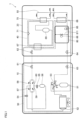
- FIG. 1 is a refrigerant circuit diagram showing an example configuration of a refrigerant circuit system according to the embodiment.
- the refrigerant circuit system 1 is, for example, a hot water supply system.
- the hot water supply system provides hot water to destinations.
- the "destinations" as referred to herein include hot water supply destinations, such as faucets, showers, and baths, as well as heating apparatuses that use hot water.
- the refrigerant circuit system 1 according to the present embodiment consists of, for example, an outdoor unit 10 installed outdoors and an indoor unit 20 installed indoors.
- the outdoor unit 10 includes a low stage-side circuit 30, a part of which is connected to the indoor unit 20.
- the indoor unit 20 includes a high stage-side circuit 40 and a heat medium circuit 50.
- the refrigerant circuit system 1 according to the present embodiment may include a control unit 100 (see FIG. 7A ).
- natural refrigerants are used as the first refrigerant to be charged in the high stage-side circuit 40 and as the second refrigerant to be charged in the low stage-side circuit 30.
- the low stage-side circuit 30 is charged with carbon dioxide
- the high stage-side circuit 40 is charged with propane.
- the low stage-side circuit 30 includes a low stage-side compressor 51, a low stage-side heat source heat exchanger 52, a four-way valve 53, a first expansion valve 54, stop valves 61, 62, 63, 64, a first cock 65, a second cock 66, a cascade heat exchanger 67, and a low stage-side utilization heat exchanger 68.
- the low stage-side circuit 30 also includes a switching circuit 80 configured to direct the refrigerant to the cascade heat exchanger 67 without directing it to the low stage-side utilization heat exchanger 68.
- the low stage-side circuit 30 may further include a second expansion valve 55, a receiver tank 56, and check valves 57, 58, 59, 60.
- the configuration of the low stage-side circuit 30 is not limited to the above.
- the low stage-side circuit 30 may be configured with a filter, heat sink, oil separator, and the like.
- the low stage-side circuit 30 may further be configured with a pressure sensor and with a high-pressure switchgear as a protective detector.
- the low stage-side compressor 51 sucks in the refrigerant from its suction side and discharges the compressed refrigerant from its discharge side.
- the low stage-side compressor 51 may include, at its suction side, an accumulator to separate the refrigerant into gas and liquid.
- the low stage-side compressor 51 has its discharge side connected to a first port (P1) of the four-way valve 53 and has its suction side connected to a third port (P3) of the four-way valve 53.
- the low stage-side heat source heat exchanger 52 exchanges heat between the refrigerant and the outdoor air.
- the low stage-side heat source heat exchanger 52 functions as an evaporator during heating operation.
- the low stage-side heat source heat exchanger 52 may be configured with an outdoor fan.
- the four-way valve 53 includes a first port (P1), a second port (P2), a third port (P3), and a fourth port (P4).
- the four-way valve 53 can switch between a state where the first port (P1) communicates with the second port (P2) and the third port (P3) communicates with the fourth port (P4) and a state where the first port (P1) communicates with the fourth port (P4) and the second port (P2) communicates with the third port (P3).
- the four-way valve 53 is in the state where the first port (P1) communicates with the second port (P2) and the third port (P3) communicates with the fourth port (P4).
- the first and second expansion valves 54, 55 are examples of the low stage-side expansion mechanism.
- the first and second expansion valves 54, 55 have a variable opening and have the function of lowering the pressure of the refrigerant circulating through the low stage-side circuit 30 to expand the refrigerant.
- the receiver tank 56 is a tank to store liquid refrigerant that has been condensed into liquid by the cascade heat exchanger 67.
- the low stage-side circuit 30 may be configured with pipes that connect the receiver tank 56 and the low stage-side compressor 51.
- the check valves 57, 58, 59, 60 are valves to prevent backflow of the refrigerant and determine the direction of the refrigerant flow.
- the refrigerant flow will be detailed below.
- the cascade heat exchanger 67 exchanges heat between the low stage-side circuit 30 and the high stage-side circuit 40.
- the cascade heat exchanger 67 includes a flow path leading to the low stage-side circuit 30 and a flow path leading to the high stage-side circuit 40.
- the cascade heat exchanger 67 is, for example, a double-pipe heat exchanger composed of two pipes of different diameters, one inside and the other outside.
- the cascade heat exchanger 67 may be any other type of heat exchanger, such as a plate heat exchanger.
- the cascade heat exchanger 67 functions as a condenser in the low stage-side circuit 30 and as an evaporator in the high stage-side circuit 40.
- the configuration of the high stage-side circuit 40 is not limited to the above.
- the high stage-side circuit 40 may be configured with a filter, heat sink, oil separator, and the like.
- the high stage-side circuit 40 may further be configured with a pressure sensor and with a high-pressure switchgear as a protective detector.
- the first cock 65 is closed and the second cock 66 is open.
- the four-way valve 53 in the low stage-side circuit 30 enables communication between the first port (P1) and the second port (P2) and communication between the third port (P3) and the fourth port (P4).
- the second refrigerant circulates along the arrows shown in FIG. 3 . More specifically, in the low stage-side circuit 30, the refrigerant in the low-pressure state (see point 91 in FIGS. 3 and 4(b) ) is first compressed by the low stage-side compressor 51. The compressed refrigerant passes through the four-way valve 53, the stop valve 63, the stop valve 64, and the second cock 66 and enters the cascade heat exchanger 67. In the first cycle, no refrigerant flows into the low stage-side utilization heat exchanger 68 and no heat exchange takes place therein, so that the state of the refrigerant does not change between points 92 and 93 in FIG. 3 (see points 92 and 93 in FIG. 4B ).
- the cascade heat exchanger 67 functions as a condenser in the low stage-side circuit 30, and the refrigerant is cooled by heat exchange with the high stage-side circuit 40 (see point 94 in FIGS. 3 and 4(b) ).
- the refrigerant leaving the cascade heat exchanger 67 passes through the stop valve 62, the stop valve 61, the check valve 60, and the second expansion valve 55 and enters the receiver tank 56.
- the refrigerant leaving the receiver tank 56 passes through the first expansion valve 54 and the check valve 57 and enters the low stage-side heat source heat exchanger 52.
- the refrigerant is decompressed as it passes through the second expansion valve 55 and the first expansion valve 54 (see point 95 in FIGS. 3 and 4(b) ).
- the low stage-side heat source heat exchanger 52 functions as an evaporator, and the refrigerant is heated by heat exchange with the outdoor air (see point 91 in FIGS. 3 and 4(b) ).
- the refrigerant leaving the low stage-side heat source heat exchanger 52 passes through the four-way valve 53 and enters the low stage-side compressor 51 again.
- the refrigerant circulates through the low stage-side circuit 30 in this manner.
- the first refrigerant circulates along the arrows shown in FIG. 3 .
- the refrigerant in the low-pressure state (see point 96 in FIGS. 3 and 4(a) ) is first compressed by the high stage-side compressor 69 (see point 97 in FIGS. 3 and 4(a) ).
- the compressed refrigerant enters the high stage-side utilization heat exchanger 70.
- the high stage-side utilization heat exchanger 70 functions as a condenser, and the refrigerant flowing through the high stage-side circuit 40 is cooled as its heat is taken away by the heat medium flowing through the heat medium circuit 50 (see point 98 in FIGS. 3 and 4(a) ).
- the refrigerant then passes through the high stage-side expansion mechanism 71, in which the refrigerant is decompressed (see point 99 in FIGS. 3 and 4(a) ).
- the decompressed refrigerant enters the cascade heat exchanger 67.
- the cascade heat exchanger 67 functions as an evaporator in the high stage-side circuit 40, and the refrigerant is heated by heat exchange with the low stage-side circuit 30 (see point 96 in FIGS. 3 and 4(a) ).
- the refrigerant leaving the cascade heat exchanger 67 enters the high stage-side compressor 69 again.
- the refrigerant circulates through the high stage-side circuit 40 in this manner.
- the heat medium flowing through the heat medium circuit 50 is warmed by heat exchange through the high stage-side utilization heat exchanger 70 with the refrigerant flowing through the high stage-side circuit 40.
- no heat exchange takes place in the low stage-side utilization heat exchanger 68.
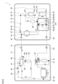
- FIG. 5 is a refrigerant circuit diagram showing the flow of refrigerant during heating operation in the second cycle according to the present embodiment.
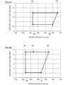
- FIGS. 6A and 6B are pressure-specific enthalpy diagrams during heating operation in the second cycle, where FIG. 6A is a pressure-specific enthalpy diagram of the high stage-side circuit 40, and FIG. 6B is a pressure-specific enthalpy diagram of the low stage-side circuit 30.
- the first cock 65 is open and the second cock 66 is closed.
- the four-way valve 53 enables communication between the first port (P1) and the second port (P2) and communication between the third port (P3) and the fourth port (P4).
- the refrigerant circulates along the arrows shown in FIG. 5 . More specifically, in the low stage-side circuit 30, the refrigerant in the low-pressure state (see point 91 in FIGS. 5 and 6(b) ) is first compressed by the low stage-side compressor 51 (see point 92 in FIGS. 5 and 6(b) ). The compressed refrigerant passes through the four-way valve 53, the stop valve 63, the stop valve 64, and the first cock 65 and enters the low stage-side utilization heat exchanger 68.
- the low stage-side utilization heat exchanger 68 functions as a condenser, and the refrigerant flowing through the low stage-side circuit 30 is cooled as its heat is taken away by the heat medium flowing through the heat medium circuit 50 (see point 93 in FIG. 5 and FIG. 6B ).
- the refrigerant leaving the low stage-side utilization heat exchanger 68 enters the cascade heat exchanger 67.
- the cascade heat exchanger 67 functions as a condenser in the low stage-side circuit 30, and the refrigerant is cooled by heat exchange with the high stage-side circuit 40 (see point 94 in FIGS. 5 and 6(b) ).
- the refrigerant leaving the cascade heat exchanger 67 passes through the stop valve 62, the stop valve 61, the check valve 60, and the second expansion valve 55 and enters the receiver tank 56.
- the refrigerant leaving the receiver tank 56 passes through the first expansion valve 54 and the check valve 57 and enters the low stage-side heat source heat exchanger 52.
- the refrigerant is decompressed as it passes through the second expansion valve 55 and the first expansion valve 54 (see point 95 in FIGS. 5 and 6(b) ).
- the low stage-side heat source heat exchanger 52 functions as an evaporator, and the refrigerant is heated by heat exchange with the outdoor air (see point 91 in FIGS. 5 and 6(b) ).
- the refrigerant leaving the low stage-side heat source heat exchanger 52 passes through the four-way valve 53 and enters the low stage-side compressor 51 again.
- the refrigerant circulates through the low stage-side circuit 30 in this manner.
- the refrigerant flow and the pressure-specific enthalpy diagram during heating operation in the second cycle are the same as in the first cycle.
- the heat medium flowing through the heat medium circuit 50 is warmed by heat exchange with the refrigerant flowing through the low stage-side circuit 30 and the high stage-side circuit 40 via the low stage-side utilization heat exchanger 68 and the high stage-side utilization heat exchanger 70, respectively.
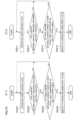
- FIG. 7B (B-1) is described.
- step 1012 determines whether the rotation speed is at or above the threshold (YES in step 1012). If the rotation speed is at or above the threshold (YES in step 1012), the control unit 100 determines whether the pump command value for controlling the water flow rate is at or below a threshold (step 1013). If the pump command value is at or above the threshold (NO in step 1013), the process returns to step 1011, and the operation using the first cycle is performed.
- step 1013 If the pump command value is at or below the threshold (YES in step 1013), the control unit 100 determines whether the hot water outlet temperature has reached a target value (step 1014). If the hot water outlet temperature has not reached the target value (NO in step 1014), the process returns to step 1011, and the operation using the first cycle is performed.
- control unit 100 switches to operation using the second cycle (step 1015).
- the compressor 69 Being at the upper rotation speed limit for the high stage-side compressor 69 means that the compressor 69 rotates at a speed equal to or higher than the upper rotation speed limit for continuously operable compressors, which is set for each compressor.
- An example of the case where the rotation speed of the high stage-side compressor 69 is at or above a threshold is when the high stage-side compressor 69 rotates at the speed that is 75% or more of its rotation capacity.
- An example of the case where the pump command value for controlling the water flow rate is at or below a certain threshold is when the output value is at or below 50%.
- the hot water outlet temperature has not reached a target value is when the outlet temperature has reached only 50°C whereas the target value is 55°C. In such a case, the control unit 100 determines that the required heating capacity to achieve the target hot water outlet temperature cannot be reached by the use of the first cycle, so that the first cycle is switched to the second cycle.
- each threshold that serves as a criterion for switching the refrigeration cycles may be variable.
- the refrigeration cycles can be switched based on the rotation speed of the high stage-side compressor 69, the pump command value, and the hot water outlet temperature.
- control unit 100 determines that the required heating capacity is not reached is when the rotation speed of the high stage-side compressor 69 is at or above the upper limit or a certain threshold, and the heating capacity estimated from the incoming water temperature, hot water outlet temperature, and pump command value has not reached the target capacity, and also the heating capacity has not improved for a certain period of time. If, in the first cycle, the heating capacity has not reached the target capacity and also the heating capacity has not improved for a certain period of time despite the high stage-side compressor 69 running at the rotation speed at or above the upper limit or a certain threshold, it is determined that the required heating capacity is not reached by the use of the first cycle.
- the first cycle is switched to the second cycle.
- the above rotation speed of the high stage-side compressor 69 and time threshold are merely examples and not limiting.
- the refrigeration cycles can be switched upon determining that the required heating capacity cannot be reached by the use of the first cycle. Also, by performing the switching upon determining that the heating capacity has not improved for a certain period of time, it is possible to prevent the refrigeration cycles from being switched before the heating capacity has been fully increased.
- control unit 100 may switch from heating operation using the first cycle to heating operation using the second cycle.
- the current heating capacity is determined by the control unit 100 based on the current hot water outlet temperature, current incoming water temperature, and water flow rate.
- the switching may be controlled based on the temperature of any other portion; for example, the switching may be controlled based on the temperature of the heat medium supplied from the heat medium pipe 86.
- the temperature is measured by, e.g., a thermometer (not shown).
- the pump command value used for making the determination to switch from the first cycle to the second cycle may be changed based on the setting of the heat medium pipe length.
- the heat medium pipe length refers to the length of the heat medium pipes 86, 87 (see FIG. 2 ) that deliver the heat medium flowing through the heat medium circuit 50 to each room where heating or hot water is used.
- the control unit 100 receives input of the heat medium pipe length and changes the pump command value according to the setting of the heat medium pipe length.
- the pump command value may be set to 70% when the heat medium pipe length is 30 m. This can compensate for the difference in water volume due to different heat medium pipe lengths.
- This configuration allows the same flow rate of water to be passed under different heat medium pipe lengths.
- the controller may switch from heating operation using the second cycle to heating operation using the first cycle.
- the first cock 65 is closed and the second cock 66 is opened.
- An example of the case where there is a margin between the current rotation speed of the high stage-side compressor 69 and its upper limit is when the current rotation speed of the high stage-side compressor 69 is less than 90% of its upper rotation speed limit.
- FIGS. 7C (C-1) and 7C (C-2) are flowcharts for switching from the second cycle to the first cycle during heating operation, where FIG. 7C (C-1) shows the case of using the required heating capacity, and FIG. 7C (C-2) shows the case of using the target hot water outlet temperature.
- FIG. 7C (C-1) is described.
- step 2001 operation using the second cycle is first performed (step 2001).
- the control unit 100 determines whether the current heating capacity has reached the required heating capacity (step 2002). If the current heating capacity has not reached the required heating capacity (NO in step 2002), the process returns to step 2001, and the operation using the second cycle is performed.
- the control unit 100 determines whether there is a margin between the current rotation speed of the high stage-side compressor 69 and the upper rotation speed limit of the high stage-side compressor 69 (step 2003). If there is no margin to the upper limit (No in step 2003), the process returns to step 2001, and the operation using the second cycle is performed.
- control unit 100 switches to the operation using the first cycle (step 2004).
- FIG. 7C (C-2) is now described.
- step 2011 operation using the second cycle is first performed (step 2011).
- the control unit 100 determines whether the current hot water outlet temperature has reached the target hot water outlet temperature (step 2012). If the current hot water outlet temperature has not reached the target hot water outlet temperature (NO in step 2012), the process returns to step 2011, and the operation using the second cycle is performed.
- the control unit 100 determines whether there is a margin between the current rotation speed of the high stage-side compressor 69 and the upper rotation speed limit of the high stage-side compressor 69 (step 2013). If there is no margin to the upper limit (No in step 2013), the process returns to step 2011, and the operation using the second cycle is performed.
- control unit 100 switches to the operation using the first cycle (step 2014).
- FIG. 7D is a flowchart for starting up the refrigerant circuit system according to the present embodiment.
- the control unit 100 puts the refrigerant circuit system 1 into operation in the first cycle (step 3002).
- the control unit 100 puts the refrigerant circuit system 1 into operation in the second cycle (step 3003).
- control flow includes a fifth step of switching to heating operation using the first cycle if (1) there is a margin between the current rotation speed of the high stage-side compressor 69 and the upper rotation speed limit of the high stage-side compressor 69, and (2) the current heating capacity has reached the required heating capacity or (3) the current hot water outlet temperature has reached the target hot water outlet temperature.
- the control unit 100 may periodically determine whether any of the following conditions (1) to (3) has been met: (1) the current rotation speed of the high stage-side compressor 69 is at the upper limit, (2) the current heating capacity has not reached the required heating capacity, and (3) the current hot water outlet temperature has not reached the target hot water outlet temperature. Also, for example, if the heating operation is currently running in the second cycle, the control unit 100 may periodically determine whether any of the following conditions (1) to (3) has been met: (1) there is a margin between the current rotation speed of the high stage-side compressor 69 and the upper rotation speed limit of the high stage-side compressor 69, (2) the current heating capacity has reached the required heating capacity, and (3) the current hot water outlet temperature has reached the target hot water outlet temperature.
- An implementation is possible where, in the event of a fault occurring in the high stage-side circuit 40, heating operation is performed only with the low stage-side circuit 30.
- a fault is any event that prevents operation using the high stage-side circuit 40, such as a failure occurring in the high stage-side compressor 69.
- An implementation is also possible where heating operation is performed only with the low stage-side circuit 30 although the failure of interest is so minor as not to prevent the operation.
- any of these implementations can ensure a certain level of heating capacity only with the low stage-side circuit 30 even if the high stage-side circuit 40 cannot be used.
- An implementation is also possible where a fault notification is issued in the event of a fault occurring in the high stage-side circuit 40.
- the user can know the unavailability of the high stage-side circuit 40 and take immediate actions.
- This implementation allows the user to know the occurrence of the fault while he/she is outside the site of interest and also allows the user himself/herself to determine whether to enable heating operation only with the low stage-side circuit.
- the high stage-side circuit 40 is installed indoors.
- propane as the refrigerant charged in the high stage-side circuit 40 and installing it indoors, according to IEC 60335-2-40 Ed. 7
- the maximum heating capacity can be reduced in the first cycle to reduce the heat exchanger volume and thus the refrigerant volume, and in the case of insufficiency in heating capacity, the first cycle can be switched to the second cycle to secure the heating capacity also in the low stage-side circuit 30, which can expand the maximum heating capacity.
- This reduction in the refrigerant volume allows the propane-charged high stage-side circuit 40 to be installed indoors where only a certain level ventilation is available.
- the refrigerant circuit system 1 of the present disclosure is a two-stage refrigerant circuit system including the high stage-side circuit (40) using the first refrigerant and the low stage-side circuit (30) using the second refrigerant, the high stage-side circuit (40) and the low stage-side circuit (30) being connected to each other via the cascade heat exchanger (67).
- the refrigerant circuit system includes: the high stage-side compressor 69, the high stage-side utilization heat exchanger 70, and the high stage-side expansion mechanism 71 in the high stage-side circuit 40; the low stage-side compressor 51, the low stage-side utilization heat exchanger 68, the first expansion valve 54, the second expansion valve 55, and the low stage-side heat source heat exchanger 52 in the low stage-side circuit 30; and the switching circuit 80 configured to switch between the first cycle and the second cycle, the first cycle being a cycle in which the refrigerant flows from the low stage-side compressor 51 to the cascade heat exchanger 67, the second cycle being a cycle in which the refrigerant flows the low stage-side compressor 51 via the low stage-side utilization heat exchanger 68 to the cascade heat exchanger 67.
- This feature allows the refrigeration cycles to be switched according to the required heating capacity.
- each of the high stage-side utilization heat exchanger 70 and the low stage-side utilization heat exchanger 68 is a water heat exchanger
- the refrigerant circuit system further includes the heat medium circuit 50 including the heat medium pipes 85, 86, 87, 89, the pump 84, and the tank 82.
- the low stage-side circuit (30) further includes the bypass flow path (811), the first cock (65), and the second cock (66).
- the refrigerant circuit system 1 of the present disclosure switches to the second cycle upon determining that the required heating capacity is not reached during heating operation using the first cycle. This feature allows the refrigeration cycles to be switched based on comparison between the current heating capacity and the required heating capacity.
- the required heating capacity is determined based on the three factors of: the hot water outlet temperature set by a user (target hot water outlet temperature); the current incoming water temperature; and the water flow rate.
- the refrigerant circuit system 1 of the present disclosure switches to the second cycle if the rotation speed of the high stage-side compressor 69 is at or above the upper limit or a certain threshold and the pump command value for controlling the heat medium flow rate is also at or below a certain threshold, but the first heat medium temperature from the heat medium pipe 87 has not reached the target value.
- This feature allows the refrigeration cycles to be switched based on the rotation speed of the high stage-side compressor 69, the pump command value, and the hot water outlet temperature.
- the refrigerant circuit system 1 of the present disclosure switches to the second cycle upon determining that the rotation speed of the high stage-side compressor 69 is at or above the upper limit or a certain threshold, and the heating capacity estimated from the incoming water temperature, the hot water outlet temperature, and the pump command value has not reached the target capacity, and the heating capacity has not improved for a certain period of time.
- This feature can prevent the refrigeration cycles from being switched before the heating capacity has been fully increased.
- the pump command value used for making the determination to switch from the first cycle to the second cycle is changed based on the setting of heat medium pipe length. This feature allows the same flow rate of water to be passed under different heat medium pipe lengths.
- the refrigerant circuit system 1 of the present disclosure performs heating operation only with the low stage-side circuit 30 in the event of a fault occurring in the high stage-side circuit 40. This feature can ensure a certain level of heating capacity only with the low stage-side circuit 30 even if the high stage-side circuit 40 cannot be used.
- the refrigerant circuit system 1 of the present disclosure issues a fault notification in the event of a fault occurring in the high stage-side circuit 40.
- This feature allows a user to know the occurrence of the fault while he/she is outside the site of interest and also allows the user himself/herself to determine whether to enable heating operation only with the low stage-side circuit 30.
- the high stage-side circuit 40 is installed indoors. This feature allows the refrigerant circuit system 1 to comply with regulations about the flammable refrigerant charge volume even if a flammable refrigerant is used in the high stage-side circuit, allowing the high stage-side circuit to be installed indoors where only a certain level ventilation is available.
- both of the above two refrigerants are natural refrigerants.
- propane is used in the high stage-side circuit 40 and carbon dioxide is used in the low stage-side circuit 30.
- the heat medium supplied by the pump 84 flows sequentially through the low stage-side utilization heat exchanger 68 and the high stage-side utilization heat exchanger 70. This feature allows the refrigeration cycles to be switched according to the required heating capacity based on switching by the switching circuit 80, without switching flow paths in the heat medium circuit 50.
- the refrigerant circuit system of the present disclosure further includes the four-way valve (53), and heating operation and cooling operation are switched by switching the four-way valve (53).
- the first cock 65 is located on the flow path connecting the low stage-side utilization heat exchanger 68 and the low stage-side compressor 51 in the bypass flow path 811 of the low stage-side circuit 30.
- this implementation is not limiting.
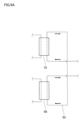
- FIG. 8A is a schematic refrigerant circuit diagram of the switching circuit in the refrigerant circuit system according to the first variant. As shown in FIG. 8A , the first cock 65 is located on the flow path connecting the low stage-side utilization heat exchanger 68 and the cascade heat exchanger 67 (see FIG. 1 ).
- FIG. 8B is a schematic refrigerant circuit diagram of the switching circuit in the refrigerant circuit system according to a second variant.
- the first and second cocks 65, 66 are used to switch whether or not to direct the second refrigerant to the low stage-side utilization heat exchanger 68.
- a three-way valve 812 is located at the junction of one end of the bypass flow path 811 and the flow path connecting the low stage-side utilization heat exchanger 68 and the low stage-side compressor 51 (see FIG. 1 ).
- FIG. 8C is a schematic refrigerant circuit diagram of the switching circuit in the refrigerant circuit system according to a third variant.
- a three-way valve 813 is located at the junction of one end of the bypass flow path 811 and the flow path connecting the low stage-side utilization heat exchanger 68 and the cascade heat exchanger 67 (see FIG. 1 ).
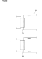
- FIG. 9A is a schematic heat medium circuit diagram in the refrigerant circuit system according to a fourth variant.
- the heat medium flows through the low stage-side utilization heat exchanger 68 and then through the high stage-side utilization heat exchanger 70.
- this implementation is not limiting.
- the heat medium flows through the high stage-side utilization heat exchanger 70 and then through the low stage-side utilization heat exchanger 68.
- FIG. 9B is a schematic heat medium circuit diagram in the refrigerant circuit system according to a fifth variant.
- the heat medium circulates independently through the low stage-side utilization heat exchanger 68 and the high stage-side utilization heat exchanger 70.
Landscapes
- Engineering & Computer Science (AREA)
- Physics & Mathematics (AREA)
- Mechanical Engineering (AREA)
- Thermal Sciences (AREA)
- General Engineering & Computer Science (AREA)
- Heat-Pump Type And Storage Water Heaters (AREA)
Abstract
Description
- The present invention relates to a refrigerant circuit system.
-
Patent Literature 1 discloses a refrigeration cycle apparatus including a high stage-side refrigerant circuit using propane, a low stage-side refrigerant circuit using carbon dioxide, and a heat medium circuit, and providing high capacity for both cooling and heating operations. - Patent Literature 1:
Japanese Patent No. 7146117 - For example, in order to further improve the cooling or heating capacity of the refrigeration cycle apparatus of
Patent Literature 1, it is necessary to increase the refrigerant charge therein. However, the use of flammable natural refrigerants, such as propane, is restricted because of their flammability. Thus, for example, refrigeration cycles that use flammable natural refrigerants cannot be charged with the refrigerant above a certain volume, which limits their capacity. - An object of the present disclosure is to propose a refrigerant circuit system that can switch refrigeration cycles according to the required heating capacity.
- An aspect of the present disclosure provides a two-stage refrigerant circuit system including a high stage-side circuit (40) using a first refrigerant and a low stage-side circuit (30) using a second refrigerant, the high stage-side circuit (40) and the low stage-side circuit (30) being connected to each other via a cascade heat exchanger (67). The refrigerant circuit system includes: a high stage-side compressor (69), a high stage-side utilization heat exchanger (70), and a high stage-side expansion mechanism (71) in the high stage-side circuit (40); a low stage-side compressor (51), a low stage-side utilization heat exchanger (68), low stage-side expansion valves (54, 55), and a low stage-side heat source heat exchanger (52) in the low stage-side circuit (30); and a switching circuit (80) configured to switch between a first cycle and a second cycle, the first cycle being a cycle in which refrigerant flows from the low stage-side compressor (51) to the cascade heat exchanger (67), the second cycle being a cycle in which the refrigerant flows from the low stage-side compressor (51) via the low stage-side utilization heat exchanger (68) to the cascade heat exchanger (67). This feature allows the refrigeration cycles to be switched according to the required heating capacity.
- In the refrigerant circuit system of the present disclosure, each of the high stage-side utilization heat exchanger (70) and the low stage-side utilization heat exchanger (68) is a water heat exchanger, and the refrigerant circuit system further includes a heat medium circuit (50) including heat medium pipes (85, 86, 87, 89), a pump (84), and a tank (82).
- In the refrigerant circuit system of the present disclosure, the low stage-side circuit (30) further includes a bypass flow path (811), a first cock (65), and a second cock (66).
- The refrigerant circuit system of the present disclosure switches to the second cycle upon determining that a required heating capacity is not reached during heating operation using the first cycle. This feature allows the refrigeration cycles to be switched based on comparison between the current heating capacity and the required heating capacity.
- In the refrigerant circuit system of the present disclosure, the required heating capacity is determined based on three factors of: a target hot water outlet temperature set by a user; a current incoming water temperature; and a water flow rate.
- The refrigerant circuit system of the present disclosure can switch to the second cycle if rotation speed of the high stage-side compressor (69) is at or above an upper limit or a certain threshold and a pump command value for controlling a heat medium flow rate is also at or below a certain threshold, but a first heat medium temperature from the heat medium pipe (87) has not reached a target value.
- The refrigerant circuit system of the present disclosure switches to the second cycle upon determining that rotation speed of the high stage-side compressor (69) is at or above an upper limit or a certain threshold, and a heating capacity estimated from an incoming water temperature, a hot water outlet temperature, and a pump command value has not reached a target capacity, and the heating capacity has not improved for a certain period of time. This feature can prevent the refrigeration cycles from being switched before the heating capacity has been fully increased.
- In the refrigerant circuit system of the present disclosure, a pump command value used for making a determination to switch from the first cycle to the second cycle is changed based on setting of a heat medium pipe length. This feature allows the same flow rate of water to be passed under different heat medium pipe lengths.
- The refrigerant circuit system of the present disclosure performs heating operation only with the low stage-side circuit (30) in the event of a fault occurring in the high stage-side circuit (40). This feature can ensure a certain level of heating capacity only with the low stage-side circuit even if the high stage-side circuit cannot be used.
- The refrigerant circuit system of the present disclosure issues a fault notification in the event of a fault occurring in the high stage-side circuit (40). This feature allows a user to know the occurrence of the fault while he/she is outside the site of interest and also allows the user himself/herself to determine whether to enable heating operation only with the low stage-side circuit.
- In the refrigerant circuit system of the present disclosure, the high stage-side circuit (40) is installed indoors. This feature allows the refrigerant circuit system to comply with regulations about the flammable refrigerant charge volume even if a flammable refrigerant is used in the high stage-side circuit, allowing the high stage-side circuit to be installed indoors where only a certain level ventilation is available.
- In the refrigerant circuit system of the present disclosure, both of the two refrigerants are natural refrigerants.
- In the refrigerant circuit system of the present disclosure, propane is used in the high stage-side circuit (40) and carbon dioxide is used in the low stage-side circuit (30).
- In the refrigerant circuit system of the present disclosure, in the heat medium circuit (50), a heat medium supplied by the pump (84) flows sequentially through the low stage-side utilization heat exchanger (68) and the high stage-side utilization heat exchanger (70). This feature allows the refrigeration cycles to be switched according to the required heating capacity based on switching by the switching circuit (80), without switching flow paths in the heat medium circuit (50).
- The refrigerant circuit system of the present disclosure further includes a four-way valve (53), and heating operation and cooling operation are switched by switching the four-way valve (53).
-
-
FIG. 1 is a refrigerant circuit diagram showing an example configuration of a refrigerant circuit system according to an exemplary embodiment. -
FIG. 2 is a heat medium circuit diagram showing an example configuration of a heat medium circuit according to the embodiment. -
FIG. 3 is a refrigerant circuit diagram showing the flow of refrigerant during heating operation in a first cycle according to the embodiment. -
FIGS. 4A and 4B are pressure-specific enthalpy diagrams during heating operation in the first cycle, whereFIG. 4A is a pressure-specific enthalpy diagram of a high stage-side circuit, andFIG. 4B is a pressure-specific enthalpy diagram of a low stage-side circuit. -
FIG. 5 is a refrigerant circuit diagram showing the flow of refrigerant during heating operation in a second cycle according to the embodiment. -
FIGS. 6A and 6B are pressure-specific enthalpy diagrams during heating operation in the second cycle, whereFIG. 6A is a pressure-specific enthalpy diagram of the high stage-side circuit, andFIG. 6B is a pressure-specific enthalpy diagram of the low stage-side circuit. -
FIG. 7A is a block diagram showing an example configuration of major devices according to the embodiment. -
FIGS. 7B (B-1) and 7B (B-2) are flowcharts for switching from the first cycle to the second cycle during heating operation, whereFIG. 7B (B-1) shows the case of using an upper rotation speed limit of a high stage-side compressor, andFIG. 7B (B-2) shows the case of using a rotation speed threshold of the high stage-side compressor. -
FIGS. 7C (C-1) and 7C (C-2) are flowcharts for switching from the second cycle to the first cycle during heating operation, whereFIG. 7C (C-1) shows the case of using the required heating capacity, andFIG. 7C (C-2) shows the case of using a target hot water outlet temperature. -
FIG. 7D is a flowchart for starting up the refrigerant circuit system according to the embodiment. -
FIG. 8A is a schematic refrigerant circuit diagram of a switching circuit in the refrigerant circuit system according to a first variant. -
FIG. 8B is a schematic refrigerant circuit diagram of the switching circuit in the refrigerant circuit system according to a second variant. -
FIG. 8C is a schematic refrigerant circuit diagram of the switching circuit in the refrigerant circuit system according to a third variant. -
FIG. 9A is a schematic heat medium circuit diagram in the refrigerant circuit system according to a fourth variant. -
FIG. 9B is a schematic heat medium circuit diagram in the refrigerant circuit system according to a fifth variant. - An exemplary embodiment of the present disclosure is described below in detail with reference to the appended drawings.
-
FIG. 1 is a refrigerant circuit diagram showing an example configuration of a refrigerant circuit system according to the embodiment. - The
refrigerant circuit system 1 according to the present embodiment is, for example, a hot water supply system. The hot water supply system provides hot water to destinations. The "destinations" as referred to herein include hot water supply destinations, such as faucets, showers, and baths, as well as heating apparatuses that use hot water. Therefrigerant circuit system 1 according to the present embodiment consists of, for example, anoutdoor unit 10 installed outdoors and anindoor unit 20 installed indoors. Theoutdoor unit 10 includes a low stage-side circuit 30, a part of which is connected to theindoor unit 20. Theindoor unit 20 includes a high stage-side circuit 40 and aheat medium circuit 50. Therefrigerant circuit system 1 according to the present embodiment may include a control unit 100 (seeFIG. 7A ). - For example, natural refrigerants are used as the first refrigerant to be charged in the high stage-
side circuit 40 and as the second refrigerant to be charged in the low stage-side circuit 30. For example, the low stage-side circuit 30 is charged with carbon dioxide, and the high stage-side circuit 40 is charged with propane. - The low stage-
side circuit 30 includes a low stage-side compressor 51, a low stage-side heatsource heat exchanger 52, a four-way valve 53, afirst expansion valve 54,stop valves first cock 65, asecond cock 66, acascade heat exchanger 67, and a low stage-sideutilization heat exchanger 68. The low stage-side circuit 30 also includes a switchingcircuit 80 configured to direct the refrigerant to thecascade heat exchanger 67 without directing it to the low stage-sideutilization heat exchanger 68. The low stage-side circuit 30 may further include asecond expansion valve 55, areceiver tank 56, andcheck valves - The configuration of the low stage-
side circuit 30 is not limited to the above. For example, the low stage-side circuit 30 may be configured with a filter, heat sink, oil separator, and the like. The low stage-side circuit 30 may further be configured with a pressure sensor and with a high-pressure switchgear as a protective detector. - The low stage-
side compressor 51 sucks in the refrigerant from its suction side and discharges the compressed refrigerant from its discharge side. The low stage-side compressor 51 may include, at its suction side, an accumulator to separate the refrigerant into gas and liquid. The low stage-side compressor 51 has its discharge side connected to a first port (P1) of the four-way valve 53 and has its suction side connected to a third port (P3) of the four-way valve 53. - The low stage-side heat
source heat exchanger 52 exchanges heat between the refrigerant and the outdoor air. The low stage-side heatsource heat exchanger 52 functions as an evaporator during heating operation. The low stage-side heatsource heat exchanger 52 may be configured with an outdoor fan. - The four-
way valve 53 includes a first port (P1), a second port (P2), a third port (P3), and a fourth port (P4). The four-way valve 53 can switch between a state where the first port (P1) communicates with the second port (P2) and the third port (P3) communicates with the fourth port (P4) and a state where the first port (P1) communicates with the fourth port (P4) and the second port (P2) communicates with the third port (P3). During heating operation, the four-way valve 53 is in the state where the first port (P1) communicates with the second port (P2) and the third port (P3) communicates with the fourth port (P4). - The first and
second expansion valves second expansion valves side circuit 30 to expand the refrigerant. - The
receiver tank 56 is a tank to store liquid refrigerant that has been condensed into liquid by thecascade heat exchanger 67. The low stage-side circuit 30 may be configured with pipes that connect thereceiver tank 56 and the low stage-side compressor 51. - The
check valves - The
stop valves outdoor unit 10 and the pipes in theindoor unit 20. - The
cascade heat exchanger 67 exchanges heat between the low stage-side circuit 30 and the high stage-side circuit 40. Thecascade heat exchanger 67 includes a flow path leading to the low stage-side circuit 30 and a flow path leading to the high stage-side circuit 40. Thecascade heat exchanger 67 is, for example, a double-pipe heat exchanger composed of two pipes of different diameters, one inside and the other outside. Alternatively, thecascade heat exchanger 67 may be any other type of heat exchanger, such as a plate heat exchanger. - During heating operation, the
cascade heat exchanger 67 functions as a condenser in the low stage-side circuit 30 and as an evaporator in the high stage-side circuit 40. - The low stage-side
utilization heat exchanger 68 exchanges heat between the low stage-side circuit 30 and theheat medium circuit 50. The low stage-sideutilization heat exchanger 68 includes a flow path leading to the low stage-side circuit 30 and a flow path leading to theheat medium circuit 50. During heating operation, the low stage-sideutilization heat exchanger 68 functions as a condenser. The heat medium flowing through theheat medium circuit 50 is warmed by taking away heat from the second refrigerant flowing through the low stage-side circuit 30, thereby performing the heating function. The low stage-sideutilization heat exchanger 68 is a water heat exchanger. However, this is not limiting, and the low stage-sideutilization heat exchanger 68 may be an air heat exchanger. - The low stage-
side circuit 30 includes abypass flow path 811. Thebypass flow path 811 connects the flow path connecting the low stage-sideutilization heat exchanger 68 and thecascade heat exchanger 67 to the flow path connecting the low stage-sideutilization heat exchanger 68 and the low stage-side compressor 51. - The first and
second cocks utilization heat exchanger 68, through their opening and closing. Thefirst cock 65 is located on the flow path connecting the low stage-sideutilization heat exchanger 68 and the low stage-side compressor 51, and thesecond cock 66 is located on thebypass flow path 811. When the refrigerant is directed to the low stage-sideutilization heat exchanger 68, thefirst cock 65 is opened and thesecond cock 66 is closed. On the other hand, when the refrigerant is not directed to the low stage-sideutilization heat exchanger 68 but is directed to thecascade heat exchanger 67 through thebypass flow path 811, thefirst cock 65 is closed and thesecond cock 66 is opened. The first andsecond cocks FIG. 7A ), according to the switching conditions described below. - The high stage-
side circuit 40 includes acascade heat exchanger 67, a high stage-side compressor 69, a high stage-sideutilization heat exchanger 70, and a high stage-side expansion mechanism 71. - The configuration of the high stage-
side circuit 40 is not limited to the above. For example, the high stage-side circuit 40 may be configured with a filter, heat sink, oil separator, and the like. The high stage-side circuit 40 may further be configured with a pressure sensor and with a high-pressure switchgear as a protective detector. - The high stage-
side compressor 69 sucks in the refrigerant from its suction side and discharges the compressed refrigerant from its discharge side. The high stage-side compressor 69 may include, at its suction side, an accumulator to separate the refrigerant into gas and liquid. The high stage-side compressor 69 has its discharge side connected to the high stage-sideutilization heat exchanger 70 and has its suction side connected to thecascade heat exchanger 67. - The high stage-side
utilization heat exchanger 70 exchanges heat between the high stage-side circuit 40 and theheat medium circuit 50. During heating operation, the high stage-sideutilization heat exchanger 70 functions as a condenser. The heat medium flowing through theheat medium circuit 50 is warmed by taking away heat from the refrigerant flowing through the high stage-side circuit 40, thereby performing the heating function. The high stage-sideutilization heat exchanger 70 is a water heat exchanger. However, this is not limiting, and the high stage-sideutilization heat exchanger 70 may be an air heat exchanger. - The high stage-
side expansion mechanism 71 has the function of lowering the pressure of the refrigerant circulating through the high stage-side circuit 40 to expand the refrigerant. For example, the high stage-side expansion mechanism 71 is a capillary tube. Due to its narrow flow path, the capillary tube creates resistance to the refrigerant flow, reducing the pressure. The high stage-side circuit 40 may be configured with an expansion valve instead of the capillary tube. -
FIG. 7A is a block diagram showing an example configuration of major components according to the present embodiment. Thecontrol unit 100 is, for example, acontroller 100. Thecontroller 100 is a device to control the operation of the hot water supply system. Thecontroller 100 includes a micro control unit (MCU), electric circuitry, and electronic circuitry. The MCU includes a central processing unit (CPU) 101, amemory 102, and a communication interface (communication I/F) 103. Thememory 102 stores various programs for execution by theCPU 101. Thecontroller 100 may be composed of one physically independent element or two or more physically separate elements. - The
controller 100 controls the low stage-side circuit 30 and the high stage-side circuit 40. Specifically, thecontroller 100 controls the low stage-side compressor 51, the high stage-side compressor 69, the four-way valve 53, and the first andsecond expansion valves - The
heat medium circuit 50 exchanges heat with the low stage-side circuit 30 and the high stage-side circuit 40 via the low stage-sideutilization heat exchanger 68 and the high stage-sideutilization heat exchanger 70, respectively, thereby providing heat exchange-based functions. Theheat medium circuit 50 is charged with a heat medium, which is, e.g., water or brine such as seawater, lake water, or antifreeze. Alternatively, theheat medium circuit 50 may be charged with antifreeze such as tetra-n-butylammonium bromide hydrate (TBAB), silicone oil, or ethylene glycol, as the heat medium. - An example configuration of the
heat medium circuit 50 is described with reference toFIG. 2. FIG. 2 is a heat medium circuit diagram showing an example configuration of theheat medium circuit 50 according to the present embodiment. - In addition to the low stage-side
utilization heat exchanger 68 and the high stage-sideutilization heat exchanger 70, theheat medium circuit 50 includes, for example, a three-way cock 81, atank 82, aheat exchanger 83, apump 84, and heatmedium pipes 85 to 89. The three-way cock 81 may be replaced with, e.g., a tee. - The heat medium flowing through the
heat medium pipe 85 of theheat medium circuit 50 is driven by thepump 84 to circulate through theheat medium pipe 85. The heat medium flowing through theheat medium pipe 85 passes through the low stage-sideutilization heat exchanger 68 and the high stage-sideutilization heat exchanger 70, during which the heat medium is warmed through heat exchange with the refrigerant flowing through the low stage-side circuit 30 and the high stage-side circuit 40. In this example, the heat medium flows through the low stage-sideutilization heat exchanger 68 and then through the high stage-sideutilization heat exchanger 70. The hot water leaving the high stage-sideutilization heat exchanger 70 is directed by the three-way cock 81 towards either thetank 82 or theheat medium pipe 86, depending on its use. - When heating is used, the three-
way cock 81 directs the hot water towards theheat medium pipe 86. Theheat medium pipe 86 leads to each room which uses heating, thus performing the heating function in each room. The water that has been used for heating and is now thus cooled returns from theheat medium pipe 89. The water returned from theheat medium pipe 89 enters the low stage-sideutilization heat exchanger 68 and then the high stage-sideutilization heat exchanger 70, where it is warmed by heat exchange before being sent to each room again. - When hot water is used, the three-
way cock 81 directs the hot water towards thetank 82. Thetank 82 stores hot water, and theheat exchanger 83 exchanges heat between the water flowing through theheat medium pipe 85 and the hot water stored in thetank 82. The hot water stored in thetank 82 is warmed by theheat exchanger 83 and sent to theheat medium pipe 87 for use as showering or other hot water supply. Meanwhile, the water flowing through theheat medium pipe 85 is cooled by theheat exchanger 83 and enters the low stage-sideutilization heat exchanger 68 and then the high stage-sideutilization heat exchanger 70, where it is warmed by heat exchange before being sent to thetank 82 again. When the hot water stored in thetank 82 is used, thetank 82 is replenished with city water or the like from theheat medium pipe 88. - The
refrigerant circuit system 1 according to the present embodiment can switch between a first cycle and a second cycle using theswitching circuit 80. The switchingcircuit 80 switches between the first cycle and the second cycle using thefirst cock 65, thesecond cock 66, and thebypass flow path 811. When using the first cycle, the low stage-side circuit 30 closes thefirst cock 65 and opens thesecond cock 66 to allow the second refrigerant to flow into thecascade heat exchanger 67 without allowing it to flow into the low stage-sideutilization heat exchanger 68. When using the second cycle, the low stage-side circuit 30 closes thefirst cock 65 and opens thesecond cock 66 to allow the second refrigerant to flow into the low stage-sideutilization heat exchanger 68 to cause heat exchange therein. - The first and second cycles and their switching conditions are described below.
- The operation of the
refrigerant circuit system 1 during heating operation in the first cycle according to the present embodiment is now described with reference toFIGS. 3 and4 .FIG. 3 is a refrigerant circuit diagram showing the flow of refrigerant during heating operation in the first cycle according to the present embodiment.FIGS. 4A and 4B are pressure-specific enthalpy diagrams during heating operation in the first cycle, whereFIG. 4A is a pressure-specific enthalpy diagram of the high stage-side circuit 40, andFIG. 4B is a pressure-specific enthalpy diagram of the low stage-side circuit 30. - In the first cycle, the
first cock 65 is closed and thesecond cock 66 is open. During heating operation, the four-way valve 53 in the low stage-side circuit 30 enables communication between the first port (P1) and the second port (P2) and communication between the third port (P3) and the fourth port (P4). - In the first cycle, the second refrigerant circulates along the arrows shown in
FIG. 3 . More specifically, in the low stage-side circuit 30, the refrigerant in the low-pressure state (seepoint 91 inFIGS. 3 and4(b) ) is first compressed by the low stage-side compressor 51. The compressed refrigerant passes through the four-way valve 53, thestop valve 63, thestop valve 64, and thesecond cock 66 and enters thecascade heat exchanger 67. In the first cycle, no refrigerant flows into the low stage-sideutilization heat exchanger 68 and no heat exchange takes place therein, so that the state of the refrigerant does not change betweenpoints FIG. 3 (seepoints FIG. 4B ). - The
cascade heat exchanger 67 functions as a condenser in the low stage-side circuit 30, and the refrigerant is cooled by heat exchange with the high stage-side circuit 40 (seepoint 94 inFIGS. 3 and4(b) ). - The refrigerant leaving the
cascade heat exchanger 67 passes through thestop valve 62, thestop valve 61, thecheck valve 60, and thesecond expansion valve 55 and enters thereceiver tank 56. The refrigerant leaving thereceiver tank 56 passes through thefirst expansion valve 54 and thecheck valve 57 and enters the low stage-side heatsource heat exchanger 52. The refrigerant is decompressed as it passes through thesecond expansion valve 55 and the first expansion valve 54 (seepoint 95 inFIGS. 3 and4(b) ). - The low stage-side heat
source heat exchanger 52 functions as an evaporator, and the refrigerant is heated by heat exchange with the outdoor air (seepoint 91 inFIGS. 3 and4(b) ). The refrigerant leaving the low stage-side heatsource heat exchanger 52 passes through the four-way valve 53 and enters the low stage-side compressor 51 again. The refrigerant circulates through the low stage-side circuit 30 in this manner. - In the high stage-
side circuit 40, the first refrigerant circulates along the arrows shown inFIG. 3 . The refrigerant in the low-pressure state (seepoint 96 inFIGS. 3 and4(a) ) is first compressed by the high stage-side compressor 69 (seepoint 97 inFIGS. 3 and4(a) ). The compressed refrigerant enters the high stage-sideutilization heat exchanger 70. The high stage-sideutilization heat exchanger 70 functions as a condenser, and the refrigerant flowing through the high stage-side circuit 40 is cooled as its heat is taken away by the heat medium flowing through the heat medium circuit 50 (seepoint 98 inFIGS. 3 and4(a) ). - The refrigerant then passes through the high stage-
side expansion mechanism 71, in which the refrigerant is decompressed (seepoint 99 inFIGS. 3 and4(a) ). The decompressed refrigerant enters thecascade heat exchanger 67. Thecascade heat exchanger 67 functions as an evaporator in the high stage-side circuit 40, and the refrigerant is heated by heat exchange with the low stage-side circuit 30 (seepoint 96 inFIGS. 3 and4(a) ). The refrigerant leaving thecascade heat exchanger 67 enters the high stage-side compressor 69 again. The refrigerant circulates through the high stage-side circuit 40 in this manner. - In the first cycle, the heat medium flowing through the
heat medium circuit 50 is warmed by heat exchange through the high stage-sideutilization heat exchanger 70 with the refrigerant flowing through the high stage-side circuit 40. On the other hand, in the first cycle, no heat exchange takes place in the low stage-sideutilization heat exchanger 68. - The operation of the
refrigerant circuit system 1 during heating operation in the second cycle according to the present embodiment is now described with reference toFIGS. 5 and6 .FIG. 5 is a refrigerant circuit diagram showing the flow of refrigerant during heating operation in the second cycle according to the present embodiment.FIGS. 6A and 6B are pressure-specific enthalpy diagrams during heating operation in the second cycle, whereFIG. 6A is a pressure-specific enthalpy diagram of the high stage-side circuit 40, andFIG. 6B is a pressure-specific enthalpy diagram of the low stage-side circuit 30. - In the second cycle, the
first cock 65 is open and thesecond cock 66 is closed. During heating operation, the four-way valve 53 enables communication between the first port (P1) and the second port (P2) and communication between the third port (P3) and the fourth port (P4). - In the second cycle, the refrigerant circulates along the arrows shown in
FIG. 5 . More specifically, in the low stage-side circuit 30, the refrigerant in the low-pressure state (seepoint 91 inFIGS. 5 and6(b) ) is first compressed by the low stage-side compressor 51 (seepoint 92 inFIGS. 5 and6(b) ). The compressed refrigerant passes through the four-way valve 53, thestop valve 63, thestop valve 64, and thefirst cock 65 and enters the low stage-sideutilization heat exchanger 68. The low stage-sideutilization heat exchanger 68 functions as a condenser, and the refrigerant flowing through the low stage-side circuit 30 is cooled as its heat is taken away by the heat medium flowing through the heat medium circuit 50 (seepoint 93 inFIG. 5 andFIG. 6B ). The refrigerant leaving the low stage-sideutilization heat exchanger 68 enters thecascade heat exchanger 67. - The
cascade heat exchanger 67 functions as a condenser in the low stage-side circuit 30, and the refrigerant is cooled by heat exchange with the high stage-side circuit 40 (seepoint 94 inFIGS. 5 and6(b) ). - The refrigerant leaving the
cascade heat exchanger 67 passes through thestop valve 62, thestop valve 61, thecheck valve 60, and thesecond expansion valve 55 and enters thereceiver tank 56. The refrigerant leaving thereceiver tank 56 passes through thefirst expansion valve 54 and thecheck valve 57 and enters the low stage-side heatsource heat exchanger 52. The refrigerant is decompressed as it passes through thesecond expansion valve 55 and the first expansion valve 54 (seepoint 95 inFIGS. 5 and6(b) ). - The low stage-side heat
source heat exchanger 52 functions as an evaporator, and the refrigerant is heated by heat exchange with the outdoor air (seepoint 91 inFIGS. 5 and6(b) ). The refrigerant leaving the low stage-side heatsource heat exchanger 52 passes through the four-way valve 53 and enters the low stage-side compressor 51 again. The refrigerant circulates through the low stage-side circuit 30 in this manner. - In the high stage-
side circuit 40, the refrigerant flow and the pressure-specific enthalpy diagram during heating operation in the second cycle are the same as in the first cycle. - In the second cycle, the heat medium flowing through the
heat medium circuit 50 is warmed by heat exchange with the refrigerant flowing through the low stage-side circuit 30 and the high stage-side circuit 40 via the low stage-sideutilization heat exchanger 68 and the high stage-sideutilization heat exchanger 70, respectively. - When, for example, a flammable refrigerant such as propane is used in the high stage-
side circuit 40, the volume of refrigerant charge is limited. Thus, in the first cycle, only a limited heating capacity is provided by heat exchange through the high stage-sideutilization heat exchanger 70. On the other hand, in the second cycle, both the low stage-sideutilization heat exchanger 68 and the high stage-sideutilization heat exchanger 70 are used for heat exchange, whereby the heat medium flowing through theheat medium circuit 50 is warmed. In the second cycle, heat exchange also takes place in the low stage-sideutilization heat exchanger 68, which can provide a higher heating capacity than when the first cycle is used. - In the second cycle, the refrigerant flowing through the low stage-
side circuit 30 is cooled in the low stage-sideutilization heat exchanger 68 and is further cooled in thecascade heat exchanger 67. This can increase the specific enthalpy compared to when the first cycle is used, enhancing the refrigeration effect. - On the other hand, in the second cycle, it is necessary to increase the high pressure to ensure the hot water outlet temperature (first heat medium temperature), which requires a higher rotation speed of compressor. In contrast, the first cycle does not require as high a pressure as is required in the second cycle, allowing for a more efficient operation.
- From the above, it is desirable to implement a highly efficient operation using the first cycle when the required heating capacity is small and, when the required heating capacity is large, switch to the second cycle to ensure the heating capacity.
- The switching between the first and second cycles in the
refrigerant circuit system 1 according to the present embodiment is described below. - In the
refrigerant circuit system 1 according to the present embodiment, switching from the heating operation using the first cycle to the heating operation using the second cycle is performed in response to, for example, thecontrol unit 100 determining that the required heating capacity is not reached. When the first cycle is switched to the second cycle, thefirst cock 65 is opened and thesecond cock 66 is closed. The required heating capacity is determined by thecontrol unit 100 based on the following three factors: the hot water outlet temperature set by a user (target hot water outlet temperature), the current incoming water temperature, and the water flow rate. - An example of the case where the
control unit 100 determines that the required heating capacity is not reached is when the rotation speed of the high stage-side compressor 69 is at or above an upper limit or a certain threshold and the pump command value for controlling the water flow rate is also at or below a certain threshold, but the hot water outlet temperature has not reached a target value. The hot water outlet temperature refers to the temperature of the water supplied from thetank 82 to theheat medium pipe 87. - An example process flow for switching from the first cycle to the second cycle during heating operation is described with reference to
FIGS. 7B (B-1) and 7B (B-2).FIGS. 7B (B-1) and 7B (B-2) are flowcharts for switching from the first cycle to the second cycle during heating operation, whereFIG. 7B (B-1) shows the case of using an upper rotation speed limit of the high stage-side compressor 69, andFIG. 7B (B-2) shows the case of using a rotation speed threshold of the high stage-side compressor 69. -
FIG. 7B (B-1) is described. - In
FIG. 7B (B-1), operation using the first cycle is first performed (step 1001). Thecontrol unit 100 determines whether the rotation speed of the high stage-side compressor 69 is at or above the upper limit (step 1002). If the rotation speed is at or below the upper limit (NO in step 1002), the process returns to step 1001, and the operation using the first cycle is performed. - If the rotation speed is at or above the upper limit (YES in step 1002), the
control unit 100 determines whether the pump command value for controlling the water flow rate is at or below a threshold (step 1003). If the pump command value is at or above the threshold (NO in step 1003), the process returns to step 1001, and the operation using the first cycle is performed. - If the pump command value is at or below the threshold (YES in step 1003), the
control unit 100 determines whether the hot water outlet temperature has reached a target value (step 1004). If the hot water outlet temperature has not reached the target value (NO in step 1004), the process returns to step 1001, and the operation using the first cycle is performed. - If the hot water outlet temperature has reached the target value (YES in step 1004), the
control unit 100 switches to operation using the second cycle (step 1005). -
FIG. 7B (B-2) is now described. - In
FIG. 7B (B-2), operation using the first cycle is first performed (step 1011). Thecontrol unit 100 determines whether the rotation speed of the high stage-side compressor 69 is at or above a threshold (step 1012). If the rotation speed is at or below the threshold (NO in step 1012), the process returns to step 1011, and the operation using the first cycle is performed. - If the rotation speed is at or above the threshold (YES in step 1012), the
control unit 100 determines whether the pump command value for controlling the water flow rate is at or below a threshold (step 1013). If the pump command value is at or above the threshold (NO in step 1013), the process returns to step 1011, and the operation using the first cycle is performed. - If the pump command value is at or below the threshold (YES in step 1013), the
control unit 100 determines whether the hot water outlet temperature has reached a target value (step 1014). If the hot water outlet temperature has not reached the target value (NO in step 1014), the process returns to step 1011, and the operation using the first cycle is performed. - If the hot water outlet temperature has reached the target value (YES in step 1014), the
control unit 100 switches to operation using the second cycle (step 1015). - Being at the upper rotation speed limit for the high stage-
side compressor 69 means that thecompressor 69 rotates at a speed equal to or higher than the upper rotation speed limit for continuously operable compressors, which is set for each compressor. An example of the case where the rotation speed of the high stage-side compressor 69 is at or above a threshold is when the high stage-side compressor 69 rotates at the speed that is 75% or more of its rotation capacity. An example of the case where the pump command value for controlling the water flow rate is at or below a certain threshold is when the output value is at or below 50%. An example of the case where the hot water outlet temperature has not reached a target value is when the outlet temperature has reached only 50°C whereas the target value is 55°C. In such a case, thecontrol unit 100 determines that the required heating capacity to achieve the target hot water outlet temperature cannot be reached by the use of the first cycle, so that the first cycle is switched to the second cycle. - The above thresholds for the rotation speed of the high stage-
side compressor 69 and the pump command value are merely examples and not limiting. For example, each threshold that serves as a criterion for switching the refrigeration cycles may be variable. - By switching between the first and second cycles according to the above switching conditions, the refrigeration cycles can be switched based on the rotation speed of the high stage-
side compressor 69, the pump command value, and the hot water outlet temperature. - An example of the case where the
control unit 100 determines that the required heating capacity is not reached is when the rotation speed of the high stage-side compressor 69 is at or above the upper limit or a certain threshold, and the heating capacity estimated from the incoming water temperature, hot water outlet temperature, and pump command value has not reached the target capacity, and also the heating capacity has not improved for a certain period of time. If, in the first cycle, the heating capacity has not reached the target capacity and also the heating capacity has not improved for a certain period of time despite the high stage-side compressor 69 running at the rotation speed at or above the upper limit or a certain threshold, it is determined that the required heating capacity is not reached by the use of the first cycle. - For example, if the high stage-
side compressor 69 is rotating at the speed that is 100% of its rotation capacity and the heating capacity estimated from the incoming water temperature, hot water outlet temperature, and pump command value has not been reaching the target capacity for five minutes, the first cycle is switched to the second cycle. - The above rotation speed of the high stage-
side compressor 69 and time threshold are merely examples and not limiting. - As the first and second cycles are switched according to the above switching conditions, the refrigeration cycles can be switched upon determining that the required heating capacity cannot be reached by the use of the first cycle. Also, by performing the switching upon determining that the heating capacity has not improved for a certain period of time, it is possible to prevent the refrigeration cycles from being switched before the heating capacity has been fully increased.
- Alternatively, if, for example, the current rotation speed of the high stage-
side compressor 69 is at the upper limit, and the current heating capacity has not reached the required heating capacity or the current hot water outlet temperature has not reached the target hot water outlet temperature, thecontrol unit 100 may switch from heating operation using the first cycle to heating operation using the second cycle. The current heating capacity is determined by thecontrol unit 100 based on the current hot water outlet temperature, current incoming water temperature, and water flow rate. - The switching may be controlled based on the temperature of any other portion; for example, the switching may be controlled based on the temperature of the heat medium supplied from the
heat medium pipe 86. The temperature is measured by, e.g., a thermometer (not shown). - The pump command value used for making the determination to switch from the first cycle to the second cycle may be changed based on the setting of the heat medium pipe length. The heat medium pipe length refers to the length of the
heat medium pipes 86, 87 (seeFIG. 2 ) that deliver the heat medium flowing through theheat medium circuit 50 to each room where heating or hot water is used. - Even with the constant pump command value, the water flow rate cannot be made constant if the heat medium pipe lengths are different. Even if the pump 84 (see
FIG. 2 ) is used with the same pump command value, the amount of water that can be passed varies depending on the heat medium pipe length. - When estimating the heating capacity from the pump command value, variations in the volume of water that can be passed depending on the heat medium pipe length make it impossible to accurately estimate the heating capacity. Thus, in order to reduce errors in estimating the heating capacity, for example, the
control unit 100 receives input of the heat medium pipe length and changes the pump command value according to the setting of the heat medium pipe length. - For example, if the pump command value is 40% when the heat medium pipe length is 15 m, the pump command value may be set to 70% when the heat medium pipe length is 30 m. This can compensate for the difference in water volume due to different heat medium pipe lengths.
- This configuration allows the same flow rate of water to be passed under different heat medium pipe lengths.
- In the
refrigerant circuit system 1 according to the present embodiment, for example, if the current heating capacity has reached the required heating capacity or the current hot water outlet temperature has reached the target hot water outlet temperature, and also there is a margin between the current rotation speed of the high stage-side compressor 69 and the upper rotation speed limit of the high stage-side compressor 69, the controller may switch from heating operation using the second cycle to heating operation using the first cycle. When switching from the second cycle to the first cycle, thefirst cock 65 is closed and thesecond cock 66 is opened. - An example of the case where there is a margin between the current rotation speed of the high stage-
side compressor 69 and its upper limit is when the current rotation speed of the high stage-side compressor 69 is less than 90% of its upper rotation speed limit. - An example process flow for switching from the second cycle to the first cycle during heating operation is described with reference to
FIGS. 7C (C-1) and 7C (C-2).FIGS. 7C (C-1) and 7C (C-2) are flowcharts for switching from the second cycle to the first cycle during heating operation, whereFIG. 7C (C-1) shows the case of using the required heating capacity, andFIG. 7C (C-2) shows the case of using the target hot water outlet temperature. -
FIG. 7C (C-1) is described. - In
FIG. 7C (C-1), operation using the second cycle is first performed (step 2001). Thecontrol unit 100 determines whether the current heating capacity has reached the required heating capacity (step 2002). If the current heating capacity has not reached the required heating capacity (NO in step 2002), the process returns to step 2001, and the operation using the second cycle is performed. - If the current heating capacity has reached the required heating capacity (YES in step 2002), the
control unit 100 determines whether there is a margin between the current rotation speed of the high stage-side compressor 69 and the upper rotation speed limit of the high stage-side compressor 69 (step 2003). If there is no margin to the upper limit (No in step 2003), the process returns to step 2001, and the operation using the second cycle is performed. - If there is a margin to the upper limit (YES in step 2003), the
control unit 100 switches to the operation using the first cycle (step 2004). -
FIG. 7C (C-2) is now described. - In
FIG. 7C (C-2), operation using the second cycle is first performed (step 2011). Thecontrol unit 100 determines whether the current hot water outlet temperature has reached the target hot water outlet temperature (step 2012). If the current hot water outlet temperature has not reached the target hot water outlet temperature (NO in step 2012), the process returns to step 2011, and the operation using the second cycle is performed. - If the current hot water outlet temperature has reached the target hot water outlet temperature (YES in step 2012), the
control unit 100 determines whether there is a margin between the current rotation speed of the high stage-side compressor 69 and the upper rotation speed limit of the high stage-side compressor 69 (step 2013). If there is no margin to the upper limit (No in step 2013), the process returns to step 2011, and the operation using the second cycle is performed. - If there is a margin to the upper limit (YES in step 2013), the
control unit 100 switches to the operation using the first cycle (step 2014). -
FIG. 7D is a flowchart for starting up the refrigerant circuit system according to the present embodiment. - When starting up the
refrigerant circuit system 1 according to the present embodiment, the control unit determines whether to perform heating operation using the first cycle or heating operation using the second cycle, based on the switching criterion capacity. The switching criterion capacity refers to an index for determining whether to use the first cycle or the second cycle during heating operation, which is determined by thecontrol unit 100 based on the target hot water outlet temperature and the outdoor air temperature. - For example, as shown in
FIG. 7D , if the switching criterion capacity exceeds the required heating capacity (YES in step 3001), thecontrol unit 100 puts therefrigerant circuit system 1 into operation in the first cycle (step 3002). On the other hand, if the switching criterion capacity is below the required heating capacity (NO in step 3001), thecontrol unit 100 puts therefrigerant circuit system 1 into operation in the second cycle (step 3003). - The control flow for the
refrigerant circuit system 1 according to the present embodiment includes, for example a first step of a user setting the hot water outlet temperature, a second step of thecontrol unit 100 calculating the required heating capacity and the switching criterion capacity, and a third step of determining whether to perform heating operation using the first cycle or heating operation using the second cycle based on the calculated switching criterion capacity. If heating operation using the first cycle is performed in the third step, then the control flow includes a fourth step of switching to heating operation using the second cycle if (1) the current rotation speed of the high stage-side compressor 69 is at the upper limit, and (2) the current heating capacity has not reached the required heating capacity or (3) the current hot water outlet temperature has not reached the target hot water outlet temperature. If heating operation using the second cycle is performed in the third step, then the control flow includes a fifth step of switching to heating operation using the first cycle if (1) there is a margin between the current rotation speed of the high stage-side compressor 69 and the upper rotation speed limit of the high stage-side compressor 69, and (2) the current heating capacity has reached the required heating capacity or (3) the current hot water outlet temperature has reached the target hot water outlet temperature. - For example, if the heating operation is currently running in the first cycle, the
control unit 100 may periodically determine whether any of the following conditions (1) to (3) has been met: (1) the current rotation speed of the high stage-side compressor 69 is at the upper limit, (2) the current heating capacity has not reached the required heating capacity, and (3) the current hot water outlet temperature has not reached the target hot water outlet temperature. Also, for example, if the heating operation is currently running in the second cycle, thecontrol unit 100 may periodically determine whether any of the following conditions (1) to (3) has been met: (1) there is a margin between the current rotation speed of the high stage-side compressor 69 and the upper rotation speed limit of the high stage-side compressor 69, (2) the current heating capacity has reached the required heating capacity, and (3) the current hot water outlet temperature has reached the target hot water outlet temperature. - An implementation is possible where, in the event of a fault occurring in the high stage-
side circuit 40, heating operation is performed only with the low stage-side circuit 30. A fault is any event that prevents operation using the high stage-side circuit 40, such as a failure occurring in the high stage-side compressor 69. An implementation is also possible where heating operation is performed only with the low stage-side circuit 30 although the failure of interest is so minor as not to prevent the operation. - Any of these implementations can ensure a certain level of heating capacity only with the low stage-
side circuit 30 even if the high stage-side circuit 40 cannot be used. - An implementation is also possible where a fault notification is issued in the event of a fault occurring in the high stage-
side circuit 40. Upon receiving the fault notification, the user can know the unavailability of the high stage-side circuit 40 and take immediate actions. This implementation allows the user to know the occurrence of the fault while he/she is outside the site of interest and also allows the user himself/herself to determine whether to enable heating operation only with the low stage-side circuit. - In the present embodiment, the high stage-
side circuit 40 is installed indoors. In the case of using propane as the refrigerant charged in the high stage-side circuit 40 and installing it indoors, according to IEC 60335-2-40 Ed. 7, there is no limitation to the floor area of the room where the circuit is installed if the refrigerant volume is 152 g or less, but if the refrigerant volume exceeds 152 g, a limitation is placed on the floor area of the room where the circuit is installed and also safety measures must be taken in case of leakage. - In the present invention, the maximum heating capacity can be reduced in the first cycle to reduce the heat exchanger volume and thus the refrigerant volume, and in the case of insufficiency in heating capacity, the first cycle can be switched to the second cycle to secure the heating capacity also in the low stage-
side circuit 30, which can expand the maximum heating capacity. This reduction in the refrigerant volume allows the propane-charged high stage-side circuit 40 to be installed indoors where only a certain level ventilation is available. - The
refrigerant circuit system 1 of the present disclosure is a two-stage refrigerant circuit system including the high stage-side circuit (40) using the first refrigerant and the low stage-side circuit (30) using the second refrigerant, the high stage-side circuit (40) and the low stage-side circuit (30) being connected to each other via the cascade heat exchanger (67). The refrigerant circuit system includes: the high stage-side compressor 69, the high stage-sideutilization heat exchanger 70, and the high stage-side expansion mechanism 71 in the high stage-side circuit 40; the low stage-side compressor 51, the low stage-sideutilization heat exchanger 68, thefirst expansion valve 54, thesecond expansion valve 55, and the low stage-side heatsource heat exchanger 52 in the low stage-side circuit 30; and the switchingcircuit 80 configured to switch between the first cycle and the second cycle, the first cycle being a cycle in which the refrigerant flows from the low stage-side compressor 51 to thecascade heat exchanger 67, the second cycle being a cycle in which the refrigerant flows the low stage-side compressor 51 via the low stage-sideutilization heat exchanger 68 to thecascade heat exchanger 67. This feature allows the refrigeration cycles to be switched according to the required heating capacity. - In the
refrigerant circuit system 1 of the present disclosure, each of the high stage-sideutilization heat exchanger 70 and the low stage-sideutilization heat exchanger 68 is a water heat exchanger, and the refrigerant circuit system further includes theheat medium circuit 50 including theheat medium pipes pump 84, and thetank 82. - In the refrigerant circuit system of the present disclosure, the low stage-side circuit (30) further includes the bypass flow path (811), the first cock (65), and the second cock (66).
- The
refrigerant circuit system 1 of the present disclosure switches to the second cycle upon determining that the required heating capacity is not reached during heating operation using the first cycle. This feature allows the refrigeration cycles to be switched based on comparison between the current heating capacity and the required heating capacity. - In the refrigerant circuit system of the present disclosure, the required heating capacity is determined based on the three factors of: the hot water outlet temperature set by a user (target hot water outlet temperature); the current incoming water temperature; and the water flow rate.
- The
refrigerant circuit system 1 of the present disclosure switches to the second cycle if the rotation speed of the high stage-side compressor 69 is at or above the upper limit or a certain threshold and the pump command value for controlling the heat medium flow rate is also at or below a certain threshold, but the first heat medium temperature from theheat medium pipe 87 has not reached the target value. This feature allows the refrigeration cycles to be switched based on the rotation speed of the high stage-side compressor 69, the pump command value, and the hot water outlet temperature. - The
refrigerant circuit system 1 of the present disclosure switches to the second cycle upon determining that the rotation speed of the high stage-side compressor 69 is at or above the upper limit or a certain threshold, and the heating capacity estimated from the incoming water temperature, the hot water outlet temperature, and the pump command value has not reached the target capacity, and the heating capacity has not improved for a certain period of time. This feature can prevent the refrigeration cycles from being switched before the heating capacity has been fully increased. - In the
refrigerant circuit system 1 of the present disclosure, the pump command value used for making the determination to switch from the first cycle to the second cycle is changed based on the setting of heat medium pipe length. This feature allows the same flow rate of water to be passed under different heat medium pipe lengths. - The
refrigerant circuit system 1 of the present disclosure performs heating operation only with the low stage-side circuit 30 in the event of a fault occurring in the high stage-side circuit 40. This feature can ensure a certain level of heating capacity only with the low stage-side circuit 30 even if the high stage-side circuit 40 cannot be used. - The
refrigerant circuit system 1 of the present disclosure issues a fault notification in the event of a fault occurring in the high stage-side circuit 40. This feature allows a user to know the occurrence of the fault while he/she is outside the site of interest and also allows the user himself/herself to determine whether to enable heating operation only with the low stage-side circuit 30. - In the
refrigerant circuit system 1 of the present disclosure, the high stage-side circuit 40 is installed indoors. This feature allows therefrigerant circuit system 1 to comply with regulations about the flammable refrigerant charge volume even if a flammable refrigerant is used in the high stage-side circuit, allowing the high stage-side circuit to be installed indoors where only a certain level ventilation is available. - In the
refrigerant circuit system 1 of the present disclosure, both of the above two refrigerants are natural refrigerants. - In the
refrigerant circuit system 1 of the present disclosure, propane is used in the high stage-side circuit 40 and carbon dioxide is used in the low stage-side circuit 30. - In the
refrigerant circuit system 1 of the present disclosure, in theheat medium circuit 50, the heat medium supplied by thepump 84 flows sequentially through the low stage-sideutilization heat exchanger 68 and the high stage-sideutilization heat exchanger 70. This feature allows the refrigeration cycles to be switched according to the required heating capacity based on switching by the switchingcircuit 80, without switching flow paths in theheat medium circuit 50. - The refrigerant circuit system of the present disclosure further includes the four-way valve (53), and heating operation and cooling operation are switched by switching the four-way valve (53).
- Variants of the
refrigerant circuit system 1 of the present disclosure described above are now described. It should be noted that the following variants can be combined as appropriate. - In the
refrigerant circuit system 1 of the present disclosure described above, thefirst cock 65 is located on the flow path connecting the low stage-sideutilization heat exchanger 68 and the low stage-side compressor 51 in thebypass flow path 811 of the low stage-side circuit 30. However, this implementation is not limiting. -
FIG. 8A is a schematic refrigerant circuit diagram of the switching circuit in the refrigerant circuit system according to the first variant. As shown inFIG. 8A , thefirst cock 65 is located on the flow path connecting the low stage-sideutilization heat exchanger 68 and the cascade heat exchanger 67 (seeFIG. 1 ). -
FIG. 8B is a schematic refrigerant circuit diagram of the switching circuit in the refrigerant circuit system according to a second variant. - In the
refrigerant circuit system 1 of the present disclosure described above, in thebypass flow path 811 of the low stage-side circuit 30, the first andsecond cocks utilization heat exchanger 68. In contrast, as shown inFIG. 8B , in therefrigerant circuit system 1 of the second variant, a three-way valve 812 is located at the junction of one end of thebypass flow path 811 and the flow path connecting the low stage-sideutilization heat exchanger 68 and the low stage-side compressor 51 (seeFIG. 1 ). -
FIG. 8C is a schematic refrigerant circuit diagram of the switching circuit in the refrigerant circuit system according to a third variant. - As shown in
FIG. 8C , in therefrigerant circuit system 1 of the third variant, a three-way valve 813 is located at the junction of one end of thebypass flow path 811 and the flow path connecting the low stage-sideutilization heat exchanger 68 and the cascade heat exchanger 67 (seeFIG. 1 ). -
FIG. 9A is a schematic heat medium circuit diagram in the refrigerant circuit system according to a fourth variant. - In the
heat medium circuit 50 of therefrigerant circuit system 1 of the present disclosure described above, the heat medium flows through the low stage-sideutilization heat exchanger 68 and then through the high stage-sideutilization heat exchanger 70. However, this implementation is not limiting. As shown inFIG. 9A , in theheat medium circuit 50 of the fourth variant, the heat medium flows through the high stage-sideutilization heat exchanger 70 and then through the low stage-sideutilization heat exchanger 68. -
FIG. 9B is a schematic heat medium circuit diagram in the refrigerant circuit system according to a fifth variant. - As shown in
FIG. 9B , in theheat medium circuit 50 of the fifth variant, the heat medium circulates independently through the low stage-sideutilization heat exchanger 68 and the high stage-sideutilization heat exchanger 70. - Although exemplary embodiments have been described above, the technical scope of the present disclosure is not limited to the scope described in the above embodiments. It will be apparent from the appended claims that combinations of two or more of the above exemplary embodiments, as well as various changes or improvements to the above exemplary embodiments, are also within the technical scope of the present disclosure.
-
- 1 Refrigerant circuit system
- 10 Outdoor unit
- 20 Indoor unit
- 30 Low stage-side circuit
- 40 High stage-side circuit
- 50 Heat medium circuit
- 51 Low stage-side compressor
- 52 Low stage-side heat source heat exchanger
- 53 Four-way valve
- 54 First expansion valve
- 55 Second expansion valve
- 67 Cascade heat exchanger
- 68 Low stage-side utilization heat exchanger
- 69 High stage-side compressor
- 70 High stage-side utilization heat exchanger
- 71 High stage-side expansion mechanism
- 80 Switching circuit
Claims (15)
- A two-stage refrigerant circuit system including a high stage-side circuit (40) using a first refrigerant and a low stage-side circuit (30) using a second refrigerant, the high stage-side circuit (40) and the low stage-side circuit (30) being connected to each other via a cascade heat exchanger (67), the refrigerant circuit system comprising:a high stage-side compressor (69), a high stage-side utilization heat exchanger (70), and a high stage-side expansion mechanism (71) in the high stage-side circuit (40);a low stage-side compressor (51), a low stage-side utilization heat exchanger (68), low stage-side expansion valves (54, 55), and a low stage-side heat source heat exchanger (52) in the low stage-side circuit (30); anda switching circuit (80) configured to switch between a first cycle and a second cycle, the first cycle being a cycle in which refrigerant flows from the low stage-side compressor (51) to the cascade heat exchanger (67), the second cycle being a cycle in which the refrigerant flows from the low stage-side compressor (51) via the low stage-side utilization heat exchanger (68) to the cascade heat exchanger (67).
- The refrigerant circuit system according to claim 1, whereineach of the high stage-side utilization heat exchanger (70) and the low stage-side utilization heat exchanger (68) is a water heat exchanger, andthe refrigerant circuit system further comprises a heat medium circuit (50) including heat medium pipes (85, 86, 87, 89), a pump (84), and a tank (82).
- The refrigerant circuit system according to claim 2, wherein the low stage-side circuit (30) further comprises a bypass flow path (811), a first cock (65), and a second cock (66).
- The refrigerant circuit system according to claim 1 or 2, wherein the refrigerant circuit system switches to the second cycle upon determining that a required heating capacity is not reached during heating operation using the first cycle.
- The refrigerant circuit system according to claim 4, wherein the required heating capacity is determined based on three factors of: a target hot water outlet temperature set by a user; a current incoming water temperature; and a water flow rate.
- The refrigerant circuit system according to claim 4, wherein the refrigerant circuit system switches to the second cycle if rotation speed of the high stage-side compressor (69) is at or above an upper limit or a certain threshold and a pump command value for controlling a heat medium flow rate is also at or below a certain threshold, but a first heat medium temperature from the heat medium pipe (87) has not reached a target value.
- The refrigerant circuit system according to claim 4, wherein the refrigerant circuit system switches to the second cycle upon determining that rotation speed of the high stage-side compressor (69) is at or above an upper limit or a certain threshold, and a heating capacity estimated from an incoming water temperature, a hot water outlet temperature, and a pump command value has not reached a target capacity, and the heating capacity has not improved for a certain period of time.
- The refrigerant circuit system according to claim 4, wherein a pump command value used for making a determination to switch from the first cycle to the second cycle is changed based on setting of a heat medium pipe length.
- The refrigerant circuit system according to claim 2, wherein the refrigerant circuit system performs heating operation only with the low stage-side circuit (30) in the event of a fault occurring in the high stage-side circuit (40).
- The refrigerant circuit system according to claims 2 to 9, wherein the refrigerant circuit system issues a fault notification in the event of a fault occurring in the high stage-side circuit (40).
- The refrigerant circuit system according to claims 2 to 9, wherein the high stage-side circuit (40) is installed indoors.
- The refrigerant circuit system according to any one of claims 2, 4, and 9, wherein both of the two refrigerants are natural refrigerants.
- The refrigerant circuit system according to claim 12, wherein propane is used in the high stage-side circuit (40) and carbon dioxide is used in the low stage-side circuit (30).
- The refrigerant circuit system according to claim 2, wherein, in the heat medium circuit (50), a heat medium supplied by the pump (84) flows sequentially through the low stage-side utilization heat exchanger (68) and the high stage-side utilization heat exchanger (70).
- The refrigerant circuit system according to claim 2, further comprising a four-way valve (53), wherein heating operation and cooling operation are switched by switching the four-way valve (53).
Applications Claiming Priority (2)
| Application Number | Priority Date | Filing Date | Title |
|---|---|---|---|
| JP2023169776 | 2023-09-29 | ||
| PCT/JP2024/034682 WO2025070734A1 (en) | 2023-09-29 | 2024-09-27 | Refrigerant circuit system |
Publications (2)
| Publication Number | Publication Date |
|---|---|
| EP4553413A1 true EP4553413A1 (en) | 2025-05-14 |
| EP4553413A4 EP4553413A4 (en) | 2025-08-06 |
Family
ID=93590952
Family Applications (1)
| Application Number | Title | Priority Date | Filing Date |
|---|---|---|---|
| EP24798712.6A Pending EP4553413A4 (en) | 2023-09-29 | 2024-09-27 | REFRIGERATING CYCLE SYSTEM |
Country Status (4)
| Country | Link |
|---|---|
| EP (1) | EP4553413A4 (en) |
| JP (2) | JP7648973B1 (en) |
| CN (1) | CN121729601A (en) |
| WO (1) | WO2025070734A1 (en) |
Family Cites Families (8)
| Publication number | Priority date | Publication date | Assignee | Title |
|---|---|---|---|---|
| JPS6277554A (en) * | 1985-09-30 | 1987-04-09 | 株式会社東芝 | Hot-water supply device |
| JP2554208B2 (en) * | 1991-02-18 | 1996-11-13 | 関西電力株式会社 | Heat pump water heater |
| JP5054180B2 (en) * | 2010-11-04 | 2012-10-24 | サンデン株式会社 | Heat pump heating system |
| JP5724476B2 (en) * | 2011-03-10 | 2015-05-27 | 株式会社富士通ゼネラル | Refrigeration cycle equipment |
| JP5939676B2 (en) * | 2012-04-24 | 2016-06-22 | 一般財団法人電力中央研究所 | Dual heat pump system and defrost method in dual heat pump system |
| JP6615345B2 (en) * | 2016-07-04 | 2019-12-04 | 三菱電機株式会社 | Refrigeration cycle system |
| JP7146117B2 (en) | 2019-11-26 | 2022-10-03 | 三菱電機株式会社 | refrigeration cycle equipment |
| CN113531935A (en) * | 2021-06-08 | 2021-10-22 | 青岛海信日立空调系统有限公司 | A cascade heat pump circulation system and control method |
-
2024
- 2024-09-27 EP EP24798712.6A patent/EP4553413A4/en active Pending
- 2024-09-27 WO PCT/JP2024/034682 patent/WO2025070734A1/en not_active Ceased
- 2024-09-27 CN CN202480054971.6A patent/CN121729601A/en active Pending
- 2024-09-27 JP JP2024168136A patent/JP7648973B1/en active Active
-
2025
- 2025-03-06 JP JP2025035300A patent/JP2025074347A/en active Pending
Also Published As
| Publication number | Publication date |
|---|---|
| CN121729601A (en) | 2026-03-24 |
| JP2025060473A (en) | 2025-04-10 |
| JP2025074347A (en) | 2025-05-13 |
| EP4553413A4 (en) | 2025-08-06 |
| JP7648973B1 (en) | 2025-03-19 |
| WO2025070734A1 (en) | 2025-04-03 |
Similar Documents
| Publication | Publication Date | Title |
|---|---|---|
| EP2789933B1 (en) | Heat pump type heating/hot-water supply system | |
| JP5306449B2 (en) | Air conditioner | |
| US9696078B2 (en) | Refrigeration cycle apparatus | |
| US11162725B2 (en) | Heat pump with hot water storage and refrigerant leak detection | |
| JP6589946B2 (en) | Refrigeration equipment | |
| US9644876B2 (en) | Refrigeration cycle apparatus | |
| CN102362126B (en) | Air conditioner | |
| JP5774128B2 (en) | Air conditioner | |
| US11248829B2 (en) | Apparatus using a heat pump including a refrigerant leakage detector | |
| CN106322768B (en) | Water heater and control method thereof | |
| JP6129520B2 (en) | Multi-type air conditioner and control method of multi-type air conditioner | |
| EP3109566B1 (en) | Air conditioning device | |
| CN117940706A (en) | Air source heat pump system | |
| EP1775528A1 (en) | Refrigeration unit | |
| EP3401609B1 (en) | Air-conditioning device | |
| JP7055239B2 (en) | Air conditioner | |
| EP3591311A1 (en) | Refrigeration cycle device | |
| JP7648973B1 (en) | Refrigerant Circuit System | |
| WO2022259396A1 (en) | Air-conditioning apparatus |
Legal Events
| Date | Code | Title | Description |
|---|---|---|---|
| STAA | Information on the status of an ep patent application or granted ep patent |
Free format text: STATUS: UNKNOWN |
|
| STAA | Information on the status of an ep patent application or granted ep patent |
Free format text: STATUS: THE INTERNATIONAL PUBLICATION HAS BEEN MADE |
|
| PUAI | Public reference made under article 153(3) epc to a published international application that has entered the european phase |
Free format text: ORIGINAL CODE: 0009012 |
|
| STAA | Information on the status of an ep patent application or granted ep patent |
Free format text: STATUS: REQUEST FOR EXAMINATION WAS MADE |
|
| 17P | Request for examination filed |
Effective date: 20241106 |
|
| AK | Designated contracting states |
Kind code of ref document: A1 Designated state(s): AL AT BE BG CH CY CZ DE DK EE ES FI FR GB GR HR HU IE IS IT LI LT LU LV MC ME MK MT NL NO PL PT RO RS SE SI SK SM TR |
|
| A4 | Supplementary search report drawn up and despatched |
Effective date: 20250704 |
|
| RIC1 | Information provided on ipc code assigned before grant |
Ipc: F25B 7/00 20060101AFI20250630BHEP Ipc: F25B 1/00 20060101ALI20250630BHEP Ipc: F25B 49/02 20060101ALI20250630BHEP Ipc: F25B 41/20 20210101ALI20250630BHEP |
|
| P01 | Opt-out of the competence of the unified patent court (upc) registered |
Free format text: CASE NUMBER: UPC_APP_3794_4553413/2025 Effective date: 20250820 |
|
| GRAP | Despatch of communication of intention to grant a patent |
Free format text: ORIGINAL CODE: EPIDOSNIGR1 |
|
| STAA | Information on the status of an ep patent application or granted ep patent |
Free format text: STATUS: GRANT OF PATENT IS INTENDED |
|
| DAV | Request for validation of the european patent (deleted) | ||
| DAX | Request for extension of the european patent (deleted) | ||
| INTG | Intention to grant announced |
Effective date: 20260507 |