EP4553412A1 - Refrigeration cycle device - Google Patents
Refrigeration cycle device Download PDFInfo
- Publication number
- EP4553412A1 EP4553412A1 EP24755178.1A EP24755178A EP4553412A1 EP 4553412 A1 EP4553412 A1 EP 4553412A1 EP 24755178 A EP24755178 A EP 24755178A EP 4553412 A1 EP4553412 A1 EP 4553412A1
- Authority
- EP
- European Patent Office
- Prior art keywords
- circuit
- heat exchanger
- refrigerant
- refrigeration cycle
- cycle apparatus
- Prior art date
- Legal status (The legal status is an assumption and is not a legal conclusion. Google has not performed a legal analysis and makes no representation as to the accuracy of the status listed.)
- Pending
Links
Images


Classifications
-
- F—MECHANICAL ENGINEERING; LIGHTING; HEATING; WEAPONS; BLASTING
- F25—REFRIGERATION OR COOLING; COMBINED HEATING AND REFRIGERATION SYSTEMS; HEAT PUMP SYSTEMS; MANUFACTURE OR STORAGE OF ICE; LIQUEFACTION SOLIDIFICATION OF GASES
- F25B—REFRIGERATION MACHINES, PLANTS OR SYSTEMS; COMBINED HEATING AND REFRIGERATION SYSTEMS; HEAT PUMP SYSTEMS
- F25B7/00—Compression machines, plants or systems, with cascade operation, i.e. with two or more circuits, the heat from the condenser of one circuit being absorbed by the evaporator of the next circuit
-
- F—MECHANICAL ENGINEERING; LIGHTING; HEATING; WEAPONS; BLASTING
- F25—REFRIGERATION OR COOLING; COMBINED HEATING AND REFRIGERATION SYSTEMS; HEAT PUMP SYSTEMS; MANUFACTURE OR STORAGE OF ICE; LIQUEFACTION SOLIDIFICATION OF GASES
- F25B—REFRIGERATION MACHINES, PLANTS OR SYSTEMS; COMBINED HEATING AND REFRIGERATION SYSTEMS; HEAT PUMP SYSTEMS
- F25B49/00—Arrangement or mounting of control or safety devices
- F25B49/02—Arrangement or mounting of control or safety devices for compression type machines, plants or systems
- F25B49/022—Compressor control arrangements
-
- F—MECHANICAL ENGINEERING; LIGHTING; HEATING; WEAPONS; BLASTING
- F25—REFRIGERATION OR COOLING; COMBINED HEATING AND REFRIGERATION SYSTEMS; HEAT PUMP SYSTEMS; MANUFACTURE OR STORAGE OF ICE; LIQUEFACTION SOLIDIFICATION OF GASES
- F25B—REFRIGERATION MACHINES, PLANTS OR SYSTEMS; COMBINED HEATING AND REFRIGERATION SYSTEMS; HEAT PUMP SYSTEMS
- F25B1/00—Compression machines, plants or systems with non-reversible cycle
-
- F—MECHANICAL ENGINEERING; LIGHTING; HEATING; WEAPONS; BLASTING
- F25—REFRIGERATION OR COOLING; COMBINED HEATING AND REFRIGERATION SYSTEMS; HEAT PUMP SYSTEMS; MANUFACTURE OR STORAGE OF ICE; LIQUEFACTION SOLIDIFICATION OF GASES
- F25B—REFRIGERATION MACHINES, PLANTS OR SYSTEMS; COMBINED HEATING AND REFRIGERATION SYSTEMS; HEAT PUMP SYSTEMS
- F25B13/00—Compression machines, plants or systems, with reversible cycle
-
- F—MECHANICAL ENGINEERING; LIGHTING; HEATING; WEAPONS; BLASTING
- F25—REFRIGERATION OR COOLING; COMBINED HEATING AND REFRIGERATION SYSTEMS; HEAT PUMP SYSTEMS; MANUFACTURE OR STORAGE OF ICE; LIQUEFACTION SOLIDIFICATION OF GASES
- F25B—REFRIGERATION MACHINES, PLANTS OR SYSTEMS; COMBINED HEATING AND REFRIGERATION SYSTEMS; HEAT PUMP SYSTEMS
- F25B40/00—Subcoolers, desuperheaters or superheaters
- F25B40/02—Subcoolers
-
- F—MECHANICAL ENGINEERING; LIGHTING; HEATING; WEAPONS; BLASTING
- F25—REFRIGERATION OR COOLING; COMBINED HEATING AND REFRIGERATION SYSTEMS; HEAT PUMP SYSTEMS; MANUFACTURE OR STORAGE OF ICE; LIQUEFACTION SOLIDIFICATION OF GASES
- F25B—REFRIGERATION MACHINES, PLANTS OR SYSTEMS; COMBINED HEATING AND REFRIGERATION SYSTEMS; HEAT PUMP SYSTEMS
- F25B43/00—Arrangements for separating or purifying gases or liquids; Arrangements for vaporising the residuum of liquid refrigerant, e.g. by heat
- F25B43/006—Accumulators
-
- F—MECHANICAL ENGINEERING; LIGHTING; HEATING; WEAPONS; BLASTING
- F25—REFRIGERATION OR COOLING; COMBINED HEATING AND REFRIGERATION SYSTEMS; HEAT PUMP SYSTEMS; MANUFACTURE OR STORAGE OF ICE; LIQUEFACTION SOLIDIFICATION OF GASES
- F25B—REFRIGERATION MACHINES, PLANTS OR SYSTEMS; COMBINED HEATING AND REFRIGERATION SYSTEMS; HEAT PUMP SYSTEMS
- F25B49/00—Arrangement or mounting of control or safety devices
- F25B49/02—Arrangement or mounting of control or safety devices for compression type machines, plants or systems
-
- F—MECHANICAL ENGINEERING; LIGHTING; HEATING; WEAPONS; BLASTING
- F25—REFRIGERATION OR COOLING; COMBINED HEATING AND REFRIGERATION SYSTEMS; HEAT PUMP SYSTEMS; MANUFACTURE OR STORAGE OF ICE; LIQUEFACTION SOLIDIFICATION OF GASES
- F25B—REFRIGERATION MACHINES, PLANTS OR SYSTEMS; COMBINED HEATING AND REFRIGERATION SYSTEMS; HEAT PUMP SYSTEMS
- F25B9/00—Compression machines, plants or systems, in which the refrigerant is air or other gas of low boiling point
- F25B9/002—Compression machines, plants or systems, in which the refrigerant is air or other gas of low boiling point characterised by the refrigerant
- F25B9/008—Compression machines, plants or systems, in which the refrigerant is air or other gas of low boiling point characterised by the refrigerant the refrigerant being carbon dioxide
-
- F—MECHANICAL ENGINEERING; LIGHTING; HEATING; WEAPONS; BLASTING
- F25—REFRIGERATION OR COOLING; COMBINED HEATING AND REFRIGERATION SYSTEMS; HEAT PUMP SYSTEMS; MANUFACTURE OR STORAGE OF ICE; LIQUEFACTION SOLIDIFICATION OF GASES
- F25B—REFRIGERATION MACHINES, PLANTS OR SYSTEMS; COMBINED HEATING AND REFRIGERATION SYSTEMS; HEAT PUMP SYSTEMS
- F25B2313/00—Compression machines, plants or systems with reversible cycle not otherwise provided for
- F25B2313/023—Compression machines, plants or systems with reversible cycle not otherwise provided for using multiple indoor units
- F25B2313/0233—Compression machines, plants or systems with reversible cycle not otherwise provided for using multiple indoor units in parallel arrangements
-
- F—MECHANICAL ENGINEERING; LIGHTING; HEATING; WEAPONS; BLASTING
- F25—REFRIGERATION OR COOLING; COMBINED HEATING AND REFRIGERATION SYSTEMS; HEAT PUMP SYSTEMS; MANUFACTURE OR STORAGE OF ICE; LIQUEFACTION SOLIDIFICATION OF GASES
- F25B—REFRIGERATION MACHINES, PLANTS OR SYSTEMS; COMBINED HEATING AND REFRIGERATION SYSTEMS; HEAT PUMP SYSTEMS
- F25B2313/00—Compression machines, plants or systems with reversible cycle not otherwise provided for
- F25B2313/031—Sensor arrangements
- F25B2313/0314—Temperature sensors near the indoor heat exchanger
-
- F—MECHANICAL ENGINEERING; LIGHTING; HEATING; WEAPONS; BLASTING
- F25—REFRIGERATION OR COOLING; COMBINED HEATING AND REFRIGERATION SYSTEMS; HEAT PUMP SYSTEMS; MANUFACTURE OR STORAGE OF ICE; LIQUEFACTION SOLIDIFICATION OF GASES
- F25B—REFRIGERATION MACHINES, PLANTS OR SYSTEMS; COMBINED HEATING AND REFRIGERATION SYSTEMS; HEAT PUMP SYSTEMS
- F25B2400/00—Component parts or details not otherwise provided for in this subclass
- F25B2400/19—Pumping down refrigerant from one part of the cycle to another part of the cycle, e.g. when the cycle is changed from cooling to heating, or before a defrost cycle is started
-
- F—MECHANICAL ENGINEERING; LIGHTING; HEATING; WEAPONS; BLASTING
- F25—REFRIGERATION OR COOLING; COMBINED HEATING AND REFRIGERATION SYSTEMS; HEAT PUMP SYSTEMS; MANUFACTURE OR STORAGE OF ICE; LIQUEFACTION SOLIDIFICATION OF GASES
- F25B—REFRIGERATION MACHINES, PLANTS OR SYSTEMS; COMBINED HEATING AND REFRIGERATION SYSTEMS; HEAT PUMP SYSTEMS
- F25B2500/00—Problems to be solved
- F25B2500/26—Problems to be solved characterised by the startup of the refrigeration cycle
-
- F—MECHANICAL ENGINEERING; LIGHTING; HEATING; WEAPONS; BLASTING
- F25—REFRIGERATION OR COOLING; COMBINED HEATING AND REFRIGERATION SYSTEMS; HEAT PUMP SYSTEMS; MANUFACTURE OR STORAGE OF ICE; LIQUEFACTION SOLIDIFICATION OF GASES
- F25B—REFRIGERATION MACHINES, PLANTS OR SYSTEMS; COMBINED HEATING AND REFRIGERATION SYSTEMS; HEAT PUMP SYSTEMS
- F25B2500/00—Problems to be solved
- F25B2500/27—Problems to be solved characterised by the stop of the refrigeration cycle
-
- F—MECHANICAL ENGINEERING; LIGHTING; HEATING; WEAPONS; BLASTING
- F25—REFRIGERATION OR COOLING; COMBINED HEATING AND REFRIGERATION SYSTEMS; HEAT PUMP SYSTEMS; MANUFACTURE OR STORAGE OF ICE; LIQUEFACTION SOLIDIFICATION OF GASES
- F25B—REFRIGERATION MACHINES, PLANTS OR SYSTEMS; COMBINED HEATING AND REFRIGERATION SYSTEMS; HEAT PUMP SYSTEMS
- F25B2600/00—Control issues
- F25B2600/02—Compressor control
- F25B2600/025—Compressor control by controlling speed
- F25B2600/0253—Compressor control by controlling speed with variable speed
-
- F—MECHANICAL ENGINEERING; LIGHTING; HEATING; WEAPONS; BLASTING
- F25—REFRIGERATION OR COOLING; COMBINED HEATING AND REFRIGERATION SYSTEMS; HEAT PUMP SYSTEMS; MANUFACTURE OR STORAGE OF ICE; LIQUEFACTION SOLIDIFICATION OF GASES
- F25B—REFRIGERATION MACHINES, PLANTS OR SYSTEMS; COMBINED HEATING AND REFRIGERATION SYSTEMS; HEAT PUMP SYSTEMS
- F25B2600/00—Control issues
- F25B2600/25—Control of valves
- F25B2600/2513—Expansion valves
-
- F—MECHANICAL ENGINEERING; LIGHTING; HEATING; WEAPONS; BLASTING
- F25—REFRIGERATION OR COOLING; COMBINED HEATING AND REFRIGERATION SYSTEMS; HEAT PUMP SYSTEMS; MANUFACTURE OR STORAGE OF ICE; LIQUEFACTION SOLIDIFICATION OF GASES
- F25B—REFRIGERATION MACHINES, PLANTS OR SYSTEMS; COMBINED HEATING AND REFRIGERATION SYSTEMS; HEAT PUMP SYSTEMS
- F25B2700/00—Sensing or detecting of parameters; Sensors therefor
- F25B2700/21—Temperatures
- F25B2700/2115—Temperatures of a compressor or the drive means therefor
- F25B2700/21152—Temperatures of a compressor or the drive means therefor at the discharge side of the compressor
-
- F—MECHANICAL ENGINEERING; LIGHTING; HEATING; WEAPONS; BLASTING
- F28—HEAT EXCHANGE IN GENERAL
- F28D—HEAT-EXCHANGE APPARATUS, NOT PROVIDED FOR IN ANOTHER SUBCLASS, IN WHICH THE HEAT-EXCHANGE MEDIA DO NOT COME INTO DIRECT CONTACT
- F28D1/00—Heat-exchange apparatus having stationary conduit assemblies for one heat-exchange medium only, the media being in contact with different sides of the conduit wall, in which the other heat-exchange medium is a large body of fluid, e.g. domestic or motor car radiators
- F28D1/02—Heat-exchange apparatus having stationary conduit assemblies for one heat-exchange medium only, the media being in contact with different sides of the conduit wall, in which the other heat-exchange medium is a large body of fluid, e.g. domestic or motor car radiators with heat-exchange conduits immersed in the body of fluid
- F28D1/04—Heat-exchange apparatus having stationary conduit assemblies for one heat-exchange medium only, the media being in contact with different sides of the conduit wall, in which the other heat-exchange medium is a large body of fluid, e.g. domestic or motor car radiators with heat-exchange conduits immersed in the body of fluid with tubular conduits
- F28D1/053—Heat-exchange apparatus having stationary conduit assemblies for one heat-exchange medium only, the media being in contact with different sides of the conduit wall, in which the other heat-exchange medium is a large body of fluid, e.g. domestic or motor car radiators with heat-exchange conduits immersed in the body of fluid with tubular conduits the conduits being straight
- F28D1/0535—Heat-exchange apparatus having stationary conduit assemblies for one heat-exchange medium only, the media being in contact with different sides of the conduit wall, in which the other heat-exchange medium is a large body of fluid, e.g. domestic or motor car radiators with heat-exchange conduits immersed in the body of fluid with tubular conduits the conduits being straight the conduits having a non-circular cross-section
- F28D1/05366—Assemblies of conduits connected to common headers, e.g. core type radiators
- F28D1/05391—Assemblies of conduits connected to common headers, e.g. core type radiators with multiple rows of conduits or with multi-channel conduits combined with a particular flow pattern, e.g. multi-row multi-stage radiators
-
- F—MECHANICAL ENGINEERING; LIGHTING; HEATING; WEAPONS; BLASTING
- F28—HEAT EXCHANGE IN GENERAL
- F28F—DETAILS OF HEAT-EXCHANGE AND HEAT-TRANSFER APPARATUS, OF GENERAL APPLICATION
- F28F1/00—Tubular elements; Assemblies of tubular elements
- F28F1/02—Tubular elements of cross-section which is non-circular
- F28F1/022—Tubular elements of cross-section which is non-circular with multiple channels
-
- F—MECHANICAL ENGINEERING; LIGHTING; HEATING; WEAPONS; BLASTING
- F28—HEAT EXCHANGE IN GENERAL
- F28F—DETAILS OF HEAT-EXCHANGE AND HEAT-TRANSFER APPARATUS, OF GENERAL APPLICATION
- F28F1/00—Tubular elements; Assemblies of tubular elements
- F28F1/10—Tubular elements and assemblies thereof with means for increasing heat-transfer area, e.g. with fins, with projections, with recesses
- F28F1/12—Tubular elements and assemblies thereof with means for increasing heat-transfer area, e.g. with fins, with projections, with recesses the means being only outside the tubular element
- F28F1/24—Tubular elements and assemblies thereof with means for increasing heat-transfer area, e.g. with fins, with projections, with recesses the means being only outside the tubular element and extending transversely
- F28F1/32—Tubular elements and assemblies thereof with means for increasing heat-transfer area, e.g. with fins, with projections, with recesses the means being only outside the tubular element and extending transversely the means having portions engaging further tubular elements
-
- F—MECHANICAL ENGINEERING; LIGHTING; HEATING; WEAPONS; BLASTING
- F28—HEAT EXCHANGE IN GENERAL
- F28F—DETAILS OF HEAT-EXCHANGE AND HEAT-TRANSFER APPARATUS, OF GENERAL APPLICATION
- F28F2215/00—Fins
- F28F2215/12—Fins with U-shaped slots for laterally inserting conduits
Definitions
- the present disclosure relates to a refrigeration cycle apparatus.
- Patent Literature 1 Japanese Patent No. 5430604 discloses heat exchange in a cascade condenser between an evaporator in a high-order refrigeration cycle and a condenser in a low-order refrigeration cycle in a binary refrigeration apparatus including the low-order refrigeration cycle using carbon dioxide as a refrigerant and the high-order refrigeration cycle supporting heat radiation in the low-order refrigeration cycle.
- the present inventor has focused on a problem that a liquid refrigerant may flow into a compressor in the binary refrigeration apparatus according to Patent Literature 1.
- the present inventor has found that this problem derives from the fact that the evaporator in the high-order refrigeration cycle in the cascade condenser is cooled and the refrigerant is liquefied when the high-order refrigeration cycle is stopped. If the high-order refrigeration cycle is operated in this state, the liquefied refrigerant flows into the compressor.
- a refrigeration cycle apparatus includes a first circuit, a second circuit, and a control unit.
- the first circuit includes a first compressor, a first heat exchanger, a first expansion mechanism, and a cascade heat exchanger.
- the first circuit allows circulation of a first refrigerant.
- the second circuit includes a second compressor, a second heat exchanger, the cascade heat exchanger, a second expansion mechanism, and a third heat exchanger.
- the second circuit allows circulation of a second refrigerant.
- the control unit executes stop control of collecting the first refrigerant in the first heat exchanger before stopping operation of the first circuit.
- the control unit executes stop control of collecting the first refrigerant in the first heat exchanger before stopping operation of the first circuit. Accordingly, the first refrigerant collected to the cascade heat exchanger can be decreased. This can inhibit liquefaction of the first refrigerant in the cascade heat exchanger while the first circuit is stopped. The first circuit is operated in this state, and the liquefied first refrigerant can thus be inhibited from flowing into the first compressor.
- a refrigeration cycle apparatus is the refrigeration cycle apparatus according to the first aspect, in which the control unit executes operation of the second circuit before operating the first circuit in cooling operation.
- the control unit operates the second circuit before operating the first circuit. Accordingly, the second refrigerant, which has passed through the second heat exchanger in the second circuit and is passing through the cascade heat exchanger, can provide heat to the first refrigerant collected to the cascade heat exchanger. The first refrigerant can be heated with use of this heat, and the liquefied first refrigerant can thus be further inhibited from flowing into the first compressor.
- a refrigeration cycle apparatus is the refrigeration cycle apparatus according to the second aspect, in which operation of the first circuit starts when difference between inlet temperature and outlet temperature of the cascade heat exchanger in the second circuit reaches a certain value or less.
- the difference between the inlet temperature and the outlet temperature of the cascade heat exchanger in the second circuit reaches the certain value or less, it is determined that heat of the second refrigerant is transferred to the first refrigerant and the first refrigerant is gasified in the cascade heat exchanger.
- the first circuit is operated in this state, and the liquefied first refrigerant can thus be further inhibited from flowing into the first compressor.
- a refrigeration cycle apparatus is the refrigeration cycle apparatus according to the second aspect, in which the control unit starts operation of the first circuit after elapse of a predetermined period from starting operation of the second circuit.
- the refrigeration cycle apparatus when the predetermined period elapses from operation of the second circuit, it is determined that heat of the second refrigerant is transferred to the first refrigerant and the first refrigerant is gasified in the cascade heat exchanger.
- the first circuit is operated in this state, and the liquefied first refrigerant can thus be further inhibited from flowing into the first compressor.
- a refrigeration cycle apparatus is the refrigeration cycle apparatus according to any one of the first to fourth aspects, in which an opening degree of the first expansion mechanism is increased after activation of the first compressor.
- the opening degree of the first expansion mechanism is not increased upon activation of the first compressor, so as to inhibit the first refrigerant in the first circuit from directly flowing into the first compressor. This can further inhibit the liquefied first refrigerant from flowing into the first compressor.
- a refrigeration cycle apparatus is the refrigeration cycle apparatus according to the fifth aspect, in which the control unit activates the second compressor, subsequently increases an opening degree of the second expansion mechanism, then activates the first compressor, and thereafter increases the opening degree of the first expansion mechanism.
- the first circuit and the second circuit can operate in the state where the liquefied first refrigerant is inhibited from flowing into the first compressor.
- a refrigeration cycle apparatus is the refrigeration cycle apparatus according to any one of the first to sixth aspects, in which the control unit controls operation of the first circuit and operation of the second circuit.
- control unit for the second circuit may control the first circuit.
- a refrigeration cycle apparatus is the refrigeration cycle apparatus according to any one of the first to seventh aspects, in which the first heat exchanger is a flat porous tube.
- the flat porous tube functioning as the first heat exchanger can be reduced in volume, so as to decrease quantity of the first refrigerant. This achieves a decrease in the first refrigerant collected to the cascade heat exchanger.
- a refrigeration cycle apparatus is the refrigeration cycle apparatus according to any one of the first to eighth aspects, and further includes a fan configured to send outdoor air to the first heat exchanger and the second heat exchanger.
- the refrigeration cycle apparatus includes the common fan configured to send outdoor air to the first heat exchanger and the second heat exchanger. Accordingly, outdoor air flows to the first heat exchanger while the second circuit is in operation even if the first circuit is stopped. Heat exchange is thus executed between the first refrigerant collected to the first heat exchanger and outdoor air, and the liquefied first refrigerant can be easily collected to the first heat exchanger. This can further inhibit the liquefied first refrigerant from flowing into the first compressor.
- a refrigeration cycle apparatus is the refrigeration cycle apparatus according to any one of the first to ninth aspects, in which the first circuit further includes an accumulator.
- the liquefied first refrigerant can be reserved in the accumulator, so as to further inhibit the liquefied first refrigerant from flowing into the first compressor.
- a refrigeration cycle apparatus is the refrigeration cycle apparatus according to any one of the first to tenth aspects, in which the control unit fully closes the first expansion mechanism while the second circuit is in operation and the first circuit is stopped.
- the first expansion mechanism is fully closed so as to decrease the first refrigerant flowing into the cascade heat exchanger. This can further inhibit the liquefied first refrigerant from flowing into the first compressor.
- a refrigeration cycle apparatus is the refrigeration cycle apparatus according to any one of the first to eleventh aspects, in which the control unit is configured to execute heating operation and cooling operation.
- operation of the first circuit is stopped during heating operation and the first refrigerant collected to the cascade heat exchanger is thus likely to be liquefied. This is likely to cause the problem that the liquefied first refrigerant flows into the first compressor. Even in a case where this problem is likely to arise, execution of stop control can inhibit the liquefied first refrigerant from flowing into the first compressor.
- a refrigeration cycle apparatus is the refrigeration cycle apparatus according to any one of the first to twelfth aspects, in which the first refrigerant is flammable, is toxic, or has a GWP (global warming potential) exceeding 500.
- the first refrigerant is flammable, is toxic, or has a GWP (global warming potential) exceeding 500.
- a refrigeration cycle apparatus 1 is configured to execute vapor compression refrigeration cycle operation to be applied for cooling or heating an indoor space of a building or the like.
- the refrigeration cycle apparatus 1 includes a first circuit 10, a second circuit 20, and a control unit 6.
- the refrigeration cycle apparatus 1 according to the present embodiment includes a binary refrigerant circuit consisting of the first circuit 10 of a vapor compression type and the second circuit 20 of the vapor compression type, and achieves a binary refrigeration cycle.
- the first circuit 10 allows circulation of a first refrigerant.
- the second circuit 20 allows circulation of a second refrigerant.
- the first circuit 10 and the second circuit 20 are thermally connected to each other via a cascade heat exchanger 30.
- the refrigeration cycle apparatus 1 includes an outdoor unit 2 and an indoor unit 3.
- the refrigeration cycle apparatus 1 includes the outdoor unit 2 and the indoor unit 3 connected to each other via connection pipes 4 and 5.
- the first refrigerant flowing in the first circuit 10 is not limited, and is flammable, is toxic, or has a GWP exceeding 500 herein.
- Examples of the first refrigerant include a hydrocarbon refrigerant, R1234yf, R1234ze, and R32, and the present embodiment adopts R290.
- the first circuit 10 constitutes a subcooling circuit during cooling operation.
- the first circuit functions as an assist circuit configured to support capability of the second circuit 20 during cooling operation.
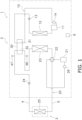
- the first circuit 10 includes a first compressor 11, the first heat exchanger 12, a first expansion mechanism 13, a first accumulator 14, and the cascade heat exchanger 30.
- the first compressor 11 is configured to compress the first refrigerant, and is exemplarily constituted as a positive displacement compressor of a scroll type configured to inverter control a compressor motor to have variable operating capacity.
- the first heat exchanger 12 is configured to cause heat exchange between the first refrigerant and outdoor air.
- the first refrigerant in the first heat exchanger 12 receives low temperature heat or high temperature heat from outdoor air.
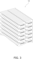
- Examples of the first heat exchanger 12 include a flat porous tube depicted in FIG. 3 .
- the first expansion mechanism 13 is configured to decompress the first refrigerant, and is exemplarily constituted as an electrically powered expansion valve.
- the first expansion mechanism 13 is disposed between the first heat exchanger 12 and the cascade heat exchanger 30.
- the first accumulator 14 is provided at a halfway position of a suction flow path connecting the cascade heat exchanger 30 and a suction side of the first compressor 11.
- the first accumulator 14 separates an incoming refrigerant into a liquid refrigerant and a gas refrigerant, and sends only the gas refrigerant to the suction side of the first compressor 11.
- the first accumulator 14 functions as a sub-accumulator accompanying an ordinary accumulator not provided. Specifically, the first accumulator 14 has half or less the volume of a second accumulator 26 included in the second circuit 20 to be described later.
- the cascade heat exchanger 30 is configured to cause heat exchange between the first refrigerant and the second refrigerant without mixing the refrigerants.
- the cascade heat exchanger 30 is exemplarily constituted as a plate heat exchanger.
- the cascade heat exchanger 30 includes a first flow path 31 belonging to the first circuit 10, and a second flow path 32 belonging to the second circuit 20.
- the first flow path 31 has a gas side connected to the first compressor 11, and a liquid side connected to the first expansion mechanism 13.
- the cascade heat exchanger 30 has an object of subcooling the second refrigerant cooled in the second heat exchanger 23, and functions as an assistant of the second circuit 20.
- the second refrigerant flowing in the second circuit 20 is not limited, and may be the same as or different from the first refrigerant.
- the second refrigerant is incombustible, is nontoxic, or has a GWP equal to or less than 500 herein.
- Examples of the second refrigerant include a natural refrigerant, and the present embodiment adopts carbon dioxide.
- the second circuit 20 is a main circuit configured to cause the second refrigerant to heat or cool indoor air.
- the second circuit 20 includes a second compressor 21, a switching mechanism 22, the second heat exchanger 23, the cascade heat exchanger 30, a second expansion mechanism 24, a third heat exchanger 25, and the second accumulator 26.
- the second compressor 21 is configured to compress the second refrigerant, and is exemplarily constituted as a positive displacement compressor of a scroll type configured to inverter control a compressor motor to have variable operating capacity.
- the switching mechanism 22 is configured to switch between a first state (see solid lines in the switching mechanism 22 in FIG. 1 ) where the second heat exchanger 23 functions as a radiator for the second refrigerant and the third heat exchanger 25 functions as an evaporator for the second refrigerant, and a second state (see broken lines in the switching mechanism 22 in FIG. 1 ) where the second heat exchanger 23 functions as an evaporator for the second refrigerant and the third heat exchanger 25 functions as a radiator for the second refrigerant.
- the switching mechanism 22 is exemplarily constituted as a four-way switching valve.
- the switching mechanism 22 in the first state connects a discharge side of the second compressor 21 and a gas side of the second heat exchanger 23, and connects a suction side of the second compressor 21 and a gas side of the third heat exchanger 25.
- the switching mechanism 22 in the second state connects the discharge side of the second compressor 21 and the gas side of the third heat exchanger 25, and connects the suction side of the second compressor 21 and the gas side of the second heat exchanger 23.
- the second heat exchanger 23 is configured to cause heat exchange between the second refrigerant and outdoor air.
- the second refrigerant in the second heat exchanger 23 receives low temperature heat or high temperature heat from outdoor air.
- the second heat exchanger 23 is exemplarily of a cross-fin tube type.
- the second circuit 20 includes the second flow path 32 of the cascade heat exchanger 30.
- the second flow path 32 has a gas side connected to the second heat exchanger 23, and a liquid side connected to the third heat exchanger 25.
- the second expansion mechanism 24 is configured to decompress the second refrigerant, and is exemplarily constituted as an electrically powered expansion valve.
- the third heat exchanger 25 is configured to cause heat exchange between the second refrigerant and indoor air, and is exemplarily constituted as a fin-and-tube heat exchanger.
- the second accumulator 26 is provided at a halfway position of a suction flow path connecting the switching mechanism 22 and the suction side of the second compressor 21.
- the second accumulator 26 separates an incoming refrigerant into a liquid refrigerant and a gas refrigerant, and sends only the gas refrigerant to the suction side of the second compressor 21.
- An up and down direction in the present embodiment is a vertical direction.
- the outdoor unit 2 is disposed in a space different from a space provided with the indoor unit 3.
- the outdoor unit 2 is disposed outdoors (on a roof of a building, adjacent to a wall surface of a building, or the like).
- the outdoor unit 2 includes the first circuit 10, part of the second circuit 20, a casing 41, an electric component unit 42, a fan 43, a partition plate 44, a separator plate 45, and various sensors.
- the outdoor unit 2 includes the first compressor 11, the first heat exchanger 12, the first expansion mechanism 13, the second compressor 21, the switching mechanism 22, the second heat exchanger 23, the second expansion mechanism 24, the second accumulator 26, the cascade heat exchanger 30, an inlet temperature sensor 46, and an outlet temperature sensor 47, which are depicted in FIG. 1 , as well as the casing 41, the electric component unit 42, the fan 43, the partition plate 44, and the separator plate 45, which are depicted in FIG. 2 .
- the casing 41 accommodates the first compressor 11, the first heat exchanger 12, the first expansion mechanism 13, the second compressor 21, the switching mechanism 22, the second heat exchanger 23, the second expansion mechanism 24, the second accumulator 26, the cascade heat exchanger 30, the electric component unit 42, the fan 43, the partition plate 44, the separator plate 45, and various sensors.
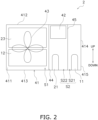
- the casing 41 depicted in FIG. 2 has a substantially rectangular parallelepiped shape. Specifically, the casing 41 includes a front panel 411, a top panel 412, a bottom plate 413, and a side plate 414.
- the front panel 411 is a plate-shaped member constituting a front surface of the casing 41.
- the front panel 411 is provided with a blow-out port.
- the blow-out port is an opening allowing outdoor air imported into the casing 41 from outside to blow out of the casing 41.
- the top panel 412 is a plate-shaped member constituting an upper surface of the casing 41.
- the bottom plate 413 is a plate-shaped member constituting a lower surface of the casing 41.
- the top panel 412 and the bottom plate 413 face each other.
- the side plate 414 is a plate-shaped member constituting a side surface of the casing 41.
- the side plate 414 has a lower portion fixed to the bottom plate 413.
- the electric component unit 42 includes a substrate and an electric component mounted onto the substrate.
- the electric component controls control targets such as the first compressor 11, the second compressor 21, the first expansion mechanism 13, the switching mechanism 22, and the second expansion mechanism 24.
- the fan 43 causes air to flow into the first heat exchanger 12 and the second heat exchanger 23.
- the fan 43 according to the present embodiment causes outdoor air to flow into both the first heat exchanger 12 and the second heat exchanger 23.
- the fan 43 generates an air flow by guiding outdoor air into the first heat exchanger 12 and the second heat exchanger 23, allowing heat exchange between the outdoor air and the first refrigerant in the first heat exchanger 12 and allowing heat exchange between the outdoor air and the second refrigerant in the second heat exchanger 23, and then allowing the air to flow outdoors.
- the fan 43 in a front view is overlapped with the first heat exchanger 12 and the second heat exchanger 23.
- the fan 43 is driven by a fan motor.
- a fan configured to send air to the first heat exchanger 12 and a separate fan configured to send air to the second heat exchanger 23.
- the partition plate 44 is a plate-shaped member extending vertically.
- the partition plate 44 has a lower portion fixed to the bottom plate 413 of the casing 41.
- the partition plate 44 divides the interior of the casing 41 into a first chamber S1 and a second chamber S2.
- Each of the first chamber S1 and the second chamber S2 is a space defined by the front panel 411, the top panel 412, the bottom plate 413, and the side plate 414 of the casing 41 and the partition plate 44.
- the first chamber S1 serves as a blast chamber, and is an air guide duct allowing air sucked via a blow-in port of the outdoor unit 2 to flow to the blow-out port.
- the first chamber S1 according to the present embodiment accommodates the first heat exchanger 12, the second heat exchanger 23, the fan 43, and the like.
- the second chamber S2 serves as a machine chamber.
- the second chamber S2 accommodates the first compressor 11, the second compressor 21, the switching mechanism 22, the first expansion mechanism 13, the second expansion mechanism 24, the second accumulator 26, the cascade heat exchanger 30, the electric component unit 42, and the like.
- the separator plate 45 divides the second chamber S2 into a first machine chamber S21 constituting the first circuit 10 and a second machine chamber S22 constituting the second circuit 20.
- the separator plate 45 is a plate-shaped member extending vertically.
- the separator plate 45 has a lower portion fixed to the bottom plate 413 of the casing 41.
- the first machine chamber S21 which is defined by the front panel 411, the top panel 412, the bottom plate 413, the side plate 414, and the separator plate 45, accommodates the first compressor 11, the first expansion mechanism 13, the cascade heat exchanger 30, and the like.
- the second machine chamber S22 which is defined by the front panel 411, the top panel 412, the bottom plate 413, the partition plate 44, and the separator plate 45, accommodates the second compressor 21, the switching mechanism 22, the second expansion mechanism 24, the second accumulator 26, the electric component unit 42, and the like.
- the inlet temperature sensor 46 detects temperature of the second refrigerant that is to flow into the cascade heat exchanger 30 during cooling operation.
- the outlet temperature sensor 47 detects temperature of the second refrigerant that has passed through the cascade heat exchanger 30 during cooling operation.
- the indoor unit 3 is installed indoors (in a building).
- the indoor unit 3 is connected to the outdoor unit 2 via the connection pipes 4 and 5 as described above, and constitutes part of the second circuit 20.
- the indoor unit 3 includes the third heat exchanger 25.
- the indoor unit 3 is installed by being embedded in or being suspended from a ceiling in an indoor space of a building or the like, or by being hung on a wall surface in the indoor space, or the like.
- connection pipes 4 and 5 are refrigerant pipes constructed onsite when the refrigeration cycle apparatus 1 is installed at an installation site such as a building.
- the connection pipe 4 on a liquid side has a first end connected to a liquid side end portion of the outdoor unit 2, and a second end connected to a liquid side end portion of the third heat exchanger 25 in the indoor unit 3.
- the connection pipe 5 on a gas side has a first end connected to a gas side end portion of the outdoor unit 2, and a second end connected to a gas side end portion of the third heat exchanger 25 in the indoor unit 3.
- the outdoor unit 2 and the indoor unit 3 each include constituent devices that are controlled by the control unit 6.
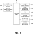
- the control unit 6 is constituted by the electric component unit 42 and the like included in the outdoor unit 2 and a control board and the like (not depicted) included in the indoor unit 3, which are communicably connected.
- the control unit 6 controls constituent devices of the refrigeration cycle apparatus 1 (the outdoor unit 2 and the indoor unit 3 herein).
- the control unit 6 is configured to control operation of the entire refrigeration cycle apparatus 1.
- the control unit 6 according to the present embodiment thus controls operation of the first circuit 10 and operation of the second circuit 20.
- the control unit 6 is provided in a unit (the second machine chamber S22 in FIG. 2 ) constituting the second circuit 20, and starts operation of the first circuit 10 in accordance with an operation start of the second circuit 20.
- the control unit 6 is embodied by a computer.
- the control unit 6 includes a control arithmetic device and a storage device.
- Examples of the control arithmetic device can include a processor such as a CPU or a GPU.
- the control arithmetic device reads a program stored in the storage device and executes predetermined image processing or arithmetic processing in accordance with the program.
- the control arithmetic device is further configured to write an arithmetic result to the storage device and read information stored in the storage device in accordance with the program.
- the control unit 6 executes stop control of collecting the first refrigerant to the first heat exchanger 12 before stopping operation of the first circuit 10. Stop control includes, when the control unit 6 receives a command to stop the first compressor 11, operating the first compressor 11 to push the first refrigerant in the first circuit 10 into the first heat exchanger 12, and then stopping the first compressor 11. Accordingly, even upon receipt of the command to stop the first compressor 11, the control unit 6 does not readily stop the first compressor 11 but continuously operates the first compressor 11 for a while to push the first refrigerant into the first heat exchanger 12, and then stops the first compressor 11.
- stop control operation of the first compressor 11 is stopped at timing such as after a predetermined period elapses from receipt of a command to stop operation of the first circuit 10, when pressure or pressure equivalent temperature on a high pressure side reaches a predetermined value or more, or when pressure or pressure equivalent temperature on a low pressure side reaches a predetermined value or less.
- the control unit 6 fully closes the first expansion mechanism 13 while the second circuit 20 is executing heating operation and the first circuit 10 is stopped.
- the control unit 6 executes start control of operating the second circuit 20 before operating the first circuit 10 in cooling operation.
- Start control includes, when the control unit 6 receives a command to activate the first circuit 10, activating the second compressor 21 before activating the first compressor 11.
- the control unit 6 starts operation of the first circuit 10 when difference between inlet temperature and outlet temperature of the cascade heat exchanger 30 in the second circuit 20 reaches a certain value or less.
- the control unit 6 acquires temperature of the second refrigerant that is to flow into the cascade heat exchanger 30 from the inlet temperature sensor 46, and temperature of the second refrigerant that has flowed out of the cascade heat exchanger 30 from the outlet temperature sensor 47.
- the control unit 6 calculates temperature difference between the inlet temperature and the outlet temperature thus acquired of the second refrigerant in the cascade heat exchanger 30 and judges whether or not the temperature difference has the certain value or less.
- the temperature difference is exemplarily 5°C or less, and is preferably 2°C or less.
- control unit 6 judges that the temperature difference thus calculated has the certain value or less, the control unit 6 activates the first compressor 11. In another case where the control unit 6 judges that the temperature difference thus calculated does not have the certain value or less, the control unit 6 does not activate the first compressor 11.
- the control unit 6 increases an opening degree of the first expansion mechanism 13 after the first compressor 11 is activated.
- the control unit 6 slightly opens the first expansion mechanism 13 to have a smaller opening degree in comparison to cooling operation.
- the control unit 6 controls the opening degree of the first expansion mechanism 13 in accordance with a load after the first refrigerant starts circulation.
- the control unit 6 activates the second compressor 21, subsequently increases an opening degree of the second expansion mechanism 24, then activates the first compressor 11, and thereafter increases the opening degree of the first expansion mechanism 13.
- the first expansion mechanism 13 is smaller in opening degree than the second expansion mechanism 24.
- the refrigeration cycle apparatus 1 is configured to execute heating operation of heating indoor air and cooling operation of cooling indoor air to condition indoor air.
- the control unit 6 controls behavior of the refrigeration cycle apparatus 1 during heating operation and cooling operation.
- the switching mechanism 22 is switched into the second state (where the switching mechanism 22 is in the state indicated by the broken lines) such that the second heat exchanger 23 functions as an evaporator for the second refrigerant and the third heat exchanger 25 functions as a radiator for the second refrigerant.
- Heating operation includes neither activation of the first compressor 11 nor circulation of the first refrigerant in the first circuit 10.
- the first expansion mechanism 13 is fully closed herein.
- the second refrigerant discharged from the second compressor 21 passes through the switching mechanism 22 and flows out of the outdoor unit 2.
- the refrigerant having flowed out of the outdoor unit 2 passes through the connection pipe 5 on the gas side and flows into the indoor unit 3.
- the second refrigerant is sent to the third heat exchanger 25 in the indoor unit 3.
- the second refrigerant sent to the third heat exchanger 25 is cooled through heat exchange with indoor air to radiate heat.
- the second refrigerant having radiated heat in the third heat exchanger 25 flows out of the indoor unit 3.
- the second refrigerant having flowed out of the indoor unit 3 passes through the connection pipe 4 on the liquid side and flows into the outdoor unit 2.
- the second refrigerant passes through the second expansion mechanism 24 and the second flow path 32 of the cascade heat exchanger 30 and is sent to the second heat exchanger 23.
- the second refrigerant sent to the second heat exchanger 23 is heated to evaporate through heat exchange with outdoor air supplied from the fan 43.
- the second refrigerant having evaporated in the second heat exchanger 23 passes through the switching mechanism 22 and the second accumulator 26 and is sucked again into the second compressor 21.
- the switching mechanism 22 is switched into the first state (where the switching mechanism 22 is in the state indicated by the solid lines) such that the second heat exchanger 23 functions as a radiator for the second refrigerant and the third heat exchanger 25 functions as an evaporator for the second refrigerant.
- the second refrigerant discharged from the second compressor 21 passes through the switching mechanism 22 and is sent to the second heat exchanger 23.
- the second refrigerant sent to the second heat exchanger 23 is cooled to radiate heat through heat exchange with outdoor air supplied from the fan 43.
- the second refrigerant having radiated heat in the second heat exchanger 23 is sent to the second flow path 32 of the cascade heat exchanger 30.
- the second refrigerant sent to the second flow path 32 is further cooled in the cascade heat exchanger 30 through heat exchange with the first refrigerant flowing in the first flow path 31.
- the second refrigerant further cooled in the cascade heat exchanger 30 is decompressed by the second expansion mechanism 24 and then flows out of the outdoor unit 2.
- the second refrigerant having flowed out of the outdoor unit 2 passes through the connection pipe 4 on the liquid side and flows into the indoor unit 3.
- the second refrigerant is sent to the third heat exchanger 25 in the indoor unit 3.
- the second refrigerant sent to the third heat exchanger 25 is heated to evaporate through heat exchange with indoor air.
- the second refrigerant having evaporated in the third heat exchanger 25 flows out of the indoor unit 3.
- the second refrigerant having flowed out of the indoor unit 3 passes through the connection pipe 5 on the gas side and flows into the outdoor unit 2.
- the second refrigerant passes through the switching mechanism 22 and the second accumulator 26 and is sucked again into the second compressor 21.
- the first refrigerant discharged from the first compressor 11 is sent to the first heat exchanger 12.
- the first refrigerant sent to the first heat exchanger 12 is cooled to radiate heat through heat exchange with outdoor air supplied from the fan 43.
- the first refrigerant having radiated heat in the first heat exchanger 12 is decompressed by the first expansion mechanism 13, and is then sent to the first flow path 31 of the cascade heat exchanger 30.
- the first refrigerant sent to the first flow path 31 is heated to evaporate in the cascade heat exchanger 30 through heat exchange with the second refrigerant flowing in the second flow path 32.
- the first refrigerant having evaporated in the cascade heat exchanger 30 passes through the first accumulator 14 and is sucked again into the first compressor 11.
- control unit 6 stops operation of the first circuit 10 and operation of the second circuit 20.
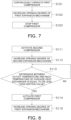
- control unit 6 having received the command stops the second compressor 21, but continues operation of the first compressor 11 as depicted in FIG. 7 (step S101). This achieves collection of the first refrigerant to the first heat exchanger 12.
- the control unit 6 further decreases the opening degree of the first expansion mechanism 13 (step S102).
- the first expansion mechanism 13 is fully closed herein.
- control unit 6 judges that the first refrigerant is collected to the first heat exchanger 12
- the control unit 6 stops the first compressor 11 (step S103). Operation of the first circuit 10 can thus be stopped.
- the opening degree of the first expansion mechanism 13 being fully closed may be slightly increased after the first compressor 11 stops.
- control unit 6 starts operation of the second circuit 20 before starting the first circuit 10.
- control unit 6 having received the command activates the second compressor 21 as depicted in FIG. 8 (step S111).
- the control unit 6 subsequently increases the opening degree of the second expansion mechanism 24 (step S112).
- the second refrigerant circulating in the second circuit 20 in step S111 and step S112 heats the liquefied first refrigerant in the cascade heat exchanger 30.
- the control unit 6 subsequently judges whether or not the difference between the inlet temperature and the outlet temperature of the cascade heat exchanger 30 in the second circuit 20 reaches the certain value or less (step S113). In step S103, the control unit 6 judges in accordance with temperature difference between inlet temperature detected by the inlet temperature sensor 46 and outlet temperature detected by the outlet temperature sensor 47.
- control unit 6 determines that the first refrigerant in the cascade heat exchanger 30 is liquefied, and continues operation of the second circuit 20 without starting operation of the first circuit 10.
- control unit 6 determines that the first refrigerant in the cascade heat exchanger 30 is gasified, and starts operation of the first circuit 10.
- control unit 6 initially activates the first compressor 11 herein (step S114).
- the control unit 6 subsequently increases the opening degree of the first expansion mechanism 13 (step S115).
- the refrigeration cycle apparatus 1 includes the first circuit 10, the second circuit 20, and the control unit 6.
- the first circuit 10 includes the first compressor 11, the first heat exchanger 12, the first expansion mechanism 13, and the cascade heat exchanger 30.
- the first circuit 10 allows circulation of the first refrigerant.
- the second circuit 20 includes the second compressor 21, the second heat exchanger 23, the cascade heat exchanger 30, the second expansion mechanism 24, and the third heat exchanger 25.
- the second circuit 20 allows circulation of the second refrigerant.
- the control unit 6 executes stop control of collecting the first refrigerant to the first heat exchanger 12 before stopping operation of the first circuit 10.
- the control unit 6 executes stop control of collecting the first refrigerant to the first heat exchanger 12 before stopping operation of the first circuit 10, so as to decrease the first refrigerant collected to the cascade heat exchanger 30.
- This can inhibit cooling to liquefy the first refrigerant in the cascade heat exchanger 30 while the first circuit 10 is stopped.
- the first circuit 10 is operated in this state, and the liquefied first refrigerant can thus be inhibited from flowing into the first compressor 11.
- the first compressor 11 can thus be inhibited from compressing (liquid compression) the liquefied first refrigerant, to reduce malfunction of the first compressor 11.
- the refrigeration cycle apparatus 1 according to the present embodiment is the refrigeration cycle apparatus 1 according to (4-1) described above, in which the control unit 6 executes operation of the second circuit 20 before operating the first circuit 10 in cooling operation.
- control unit 6 operates the second circuit 20 before operating the first circuit 10. Accordingly, the second refrigerant, which has high pressure, has passed through the second heat exchanger 23 in the second circuit 20, and is passing through the cascade heat exchanger 30, can provide heat to the first refrigerant collected to the cascade heat exchanger 30.
- the first refrigerant can be heated with such heat.
- the liquefied first refrigerant can thus be gasified. Accordingly, this can further inhibit the liquefied first refrigerant from flowing into the first compressor 11.
- control unit 6 preferably operates the second circuit 20 before operating the first circuit 10 in(during) initial cooling operation subsequent to heating operation. Described below is a reason therefor.
- operating the second circuit 20 before operation of the first circuit 10 in initial cooling operation subsequent to heating operation can allow the liquefied first refrigerant in the first flow path 31 of the cascade heat exchanger 30 to be gasified when the second refrigerant having high pressure and having passed through the second heat exchanger 23 passes through the second flow path 32 of the cascade heat exchanger 30.
- the refrigeration cycle apparatus 1 according to the present embodiment is the refrigeration cycle apparatus 1 according to (4-2) described above, in which operation of the first circuit 10 starts when the difference between the inlet temperature and the outlet temperature of the cascade heat exchanger 30 in the second circuit 20 reaches the certain value or less.
- the difference between the inlet temperature and the outlet temperature of the cascade heat exchanger 30 in the second circuit 20 reaches the certain value or less, it is determined that heat of the second refrigerant is transferred to the first refrigerant and the first refrigerant is gasified in the cascade heat exchanger 30.
- the first circuit 10 is operated in this state, and the liquefied first refrigerant can thus be further inhibited from flowing into the first compressor 11.
- the refrigeration cycle apparatus according to the present embodiment is the refrigeration cycle apparatus according to any one of (4-1) to (4-3) described above, in which the first expansion mechanism 13 is increased in opening degree after activation of the first compressor 11.
- the opening degree of the first expansion mechanism 13 is slightly opened or fully closed upon activation of the first compressor 11, so as to inhibit the first refrigerant in the first circuit 10 from directly flowing into the first compressor 11. This can further inhibit the liquefied first refrigerant from flowing into the first compressor 11.
- the refrigeration cycle apparatus 1 according to the present embodiment is the refrigeration cycle apparatus 1 according to (4-4) described above, in which the control unit 6 activates the second compressor 21, subsequently increases the opening degree of the second expansion mechanism 24, then activates the first compressor 11, and thereafter increases the opening degree of the first expansion mechanism 13.
- the first circuit 10 and the second circuit 20 can operate in the state where the liquefied first refrigerant is inhibited from flowing into the first compressor 11.
- the refrigeration cycle apparatus 1 according to the present embodiment is the refrigeration cycle apparatus 1 according to any one of (4-1) to (4-5) described above, in which the control unit 6 controls operation of the first circuit 10 and operation of the second circuit 20.
- control unit for the second circuit 20 may control the first circuit 10.
- the refrigeration cycle apparatus 1 is the refrigeration cycle apparatus 1 according to any one of (4-1) to (4-6) described above, in which the first heat exchanger 12 is a flat porous tube.
- the flat porous tube functioning as the first heat exchanger 12 can be reduced in volume, so as to decrease quantity of the first refrigerant. This achieves a decrease in the first refrigerant collected to the cascade heat exchanger 30.
- the refrigeration cycle apparatus 1 according to the present embodiment is the refrigeration cycle apparatus 1 according to any one of (4-1) to (4-7) described above, and further includes the fan 43 configured to send outdoor air to the first heat exchanger 12 and the second heat exchanger 23.
- the fan 43 is commonly provided to send outdoor air to the first heat exchanger 12 and the second heat exchanger 23. Accordingly, outdoor air flows to the first heat exchanger 12 while the second circuit 20 is in operation even if the first circuit 10 is stopped. Heat exchange is thus executed between the first refrigerant collected to the first heat exchanger 12 and outdoor air, and the liquefied first refrigerant can be easily collected to the first heat exchanger 12. This can further inhibit the liquefied first refrigerant from flowing into the first compressor 11.
- the refrigeration cycle apparatus 1 is the refrigeration cycle apparatus 1 according to any one of (4-1) to (4-8) described above, in which the first circuit 10 further includes the first accumulator 14.
- the liquefied first refrigerant can be reserved in the first accumulator 14, so as to further inhibit the liquefied first refrigerant from flowing into the first compressor 11.
- the liquid refrigerant cannot be perfectly prevented from flowing into the first compressor 11 even when first circuit 10 includes the first accumulator 14, to achieve inhibition of liquid compression through execution of stop control according to the present embodiment.
- the refrigeration cycle apparatus 1 is the refrigeration cycle apparatus 1 according to any one of (4-1) to (4-9) described above, in which the control unit 6 fully closes the first expansion mechanism 13 while the second circuit 20 is executing heating operation and the first circuit 10 is stopped.
- the second circuit 20 While the second circuit 20 is executing heating operation, the second refrigerant having low pressure passes through the second flow path 32 of the cascade heat exchanger 30. Accordingly, while the second circuit 20 is executing heating operation and the first circuit 10 is stopped, the first refrigerant collected to the first flow path 31 of the cascade heat exchanger 30 is likely to be cooled and liquefied.
- the first expansion mechanism 13 is fully closed in this case so as to decrease the first refrigerant flowing into the cascade heat exchanger 30 to be liquefied. This can further inhibit the liquefied first refrigerant from flowing into the first compressor 11.
- the refrigeration cycle apparatus 1 according to the present embodiment is the refrigeration cycle apparatus 1 according to any one of (4-1) to (4-10) described above, in which the control unit 6 is configured to execute heating operation and cooling operation.
- the first refrigerant collected to the cascade heat exchanger 30 is likely to be liquefied when operation of the first circuit 10 is stopped during heating operation. This is likely to cause a problem that the liquefied first refrigerant flows into the first compressor 11. Even in a case where this problem is likely to arise, execution of stop control can inhibit the liquefied first refrigerant from flowing into the first compressor 11.
- the refrigeration cycle apparatus 1 is the refrigeration cycle apparatus 1 according to any one of (4-1) to (4-11) described above, in which the first refrigerant is flammable, is toxic, or has a GWP exceeding 500.
- the first refrigerant may be flammable, be toxic, or have a GWP exceeding 500.
- the refrigeration cycle apparatus 1 according to the present embodiment is the refrigeration cycle apparatus 1 according to (4-12) described above, in which the first refrigerant is R290 and the second refrigerant is carbon dioxide.
- Carbon dioxide as a refrigerant has a low GWP and can thus contribute to inhibition of global warming, but is less likely to exert capability during cooling operation at high outdoor air temperature.
- the refrigeration cycle apparatus 1 includes the first circuit 10 functioning as a subcooling circuit and allowing circulation of R290, and can thus exert higher capability.
- control unit 6 executes start control upon cooling operation by starting operation of the first circuit 10 when the difference between the inlet temperature and the outlet temperature of the cascade heat exchanger 30 in the second circuit 20 reaches the certain value or less.
- the present disclosure is not limited to this case.
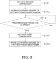
- the control unit 6 starts operation of the first circuit 10 after elapse of the predetermined period from starting operation of the second circuit 20.
- the predetermined period may be three minutes or more, and is preferably ten minutes or more.
- the control unit 6 judges whether or not the predetermined period has elapsed after activation of the second compressor 21 (step S116). In a case where the control unit 6 judges that the predetermined period has elapsed, the control unit 6 activates the first compressor 11 (step S114). In another case where the control unit 6 judges that the predetermined period has not elapsed, the control unit 6 does not activate the first compressor 11.
- a refrigeration cycle apparatus is the refrigeration cycle apparatus according to (4-2) described above, in which the control unit 6 starts operation of the first circuit 10 after the predetermined period has elapsed from starting operation of the second circuit 20.
- the predetermined period elapses from operation of the second circuit 20 it is determined that heat of the second refrigerant is transferred to the first refrigerant and the first refrigerant is gasified in the cascade heat exchanger 30.
- the first circuit 10 is operated in this state, and the liquefied first refrigerant can thus be further inhibited from flowing into the first compressor 11.
- the above embodiment exemplarily describes control of fully closing the first expansion mechanism 13 while the second circuit 20 is executing heating operation and the first circuit 10 is stopped.
- the first expansion mechanism 13 may be fully closed also while the first circuit 10 is stopped because the second circuit 20 is executing cooling operation.
- control unit 6 in this manner, fully closes the first expansion mechanism 13 while the second circuit 20 is in operation and the first circuit 10 is stopped.
- the first expansion mechanism 13 is fully closed so as to decrease the first refrigerant flowing into the cascade heat exchanger 30. This can further inhibit the liquefied first refrigerant from flowing into the first compressor 11.
- the above embodiment exemplarily describes executing start control and stop control when cooling operation starts and is stopped.
- Such start control and stop control may be applied to a case of stopping or starting operation of the first circuit 10 during cooling operation.
- control unit 6 may control to operate the first circuit 10 in accordance with a load during cooling operation. More specifically, the control unit 6 does not operate the first circuit 10 when the load is low during cooling operation, and operates the first circuit 10 when the load is high during cooling operation. In this case, the control unit 6 executes start control described above to operate the first circuit 10 when the load is high during cooling operation. The control unit 6 executes stop control described above to stop operation of the first circuit 10 when the load is low during cooling operation.
- control unit 6 is provided in the second machine chamber S22 of the second circuit 20, and starts operation of the first circuit 10 in accordance with an operation start of the second circuit 20.
- the present disclosure is not limited to this case.
- the control unit according to the present modification example includes a first control unit configured to control operation of the first circuit 10 and a second control unit configured to control operation of the second circuit 20, and the first control unit starts operation of the first circuit 10 in accordance with a command from the second control unit.
- the first circuit 10 includes the first accumulator 14.
- the first circuit according to the present disclosure may include an accumulator and a sub-accumulator.
- the first circuit according to the present modification example includes neither an accumulator nor a sub-accumulator. This achieves a further decrease in quantity of the first refrigerant filled into the first circuit 10.
- the refrigeration cycle apparatus 1 is therefore quite useful in a case of adopting an extremely flammable (A3) refrigerant such as R290.
- a refrigeration cycle apparatus includes a first fan configured to send outdoor air to the first heat exchanger 12 and a second fan configured to send outdoor air to the second heat exchanger 23, and the first fan and the second fan are provided separately from each other.
- a refrigeration cycle apparatus includes a plurality of indoor units connected to a single outdoor unit.
- the above embodiment exemplarily describes the refrigeration cycle apparatus 1 configured to execute cooling operation and heating operation.
- the refrigeration cycle apparatus according to the present disclosure may be configured to further execute dehumidifying operation. During dehumidifying operation, stop control and start control are executed as in cooling operation according to the above embodiment.
- the refrigeration cycle apparatus according to the present disclosure may alternatively be constituted as an air conditioner dedicated to cooling.
- Patent Literature 1 Japanese Patent No. 5430604
Landscapes
- Engineering & Computer Science (AREA)
- Physics & Mathematics (AREA)
- Mechanical Engineering (AREA)
- Thermal Sciences (AREA)
- General Engineering & Computer Science (AREA)
- Chemical & Material Sciences (AREA)
- Analytical Chemistry (AREA)
- Power Engineering (AREA)
- Chemical Kinetics & Catalysis (AREA)
- Air Conditioning Control Device (AREA)
- Compression-Type Refrigeration Machines With Reversible Cycles (AREA)
Abstract
Description
- The present disclosure relates to a refrigeration cycle apparatus.
- Patent Literature 1 (
Japanese Patent No. 5430604 - The present inventor has focused on a problem that a liquid refrigerant may flow into a compressor in the binary refrigeration apparatus according to
Patent Literature 1. - The present inventor has found that this problem derives from the fact that the evaporator in the high-order refrigeration cycle in the cascade condenser is cooled and the refrigerant is liquefied when the high-order refrigeration cycle is stopped. If the high-order refrigeration cycle is operated in this state, the liquefied refrigerant flows into the compressor.
- In view of this, a refrigeration cycle apparatus according to a first aspect includes a first circuit, a second circuit, and a control unit. The first circuit includes a first compressor, a first heat exchanger, a first expansion mechanism, and a cascade heat exchanger. The first circuit allows circulation of a first refrigerant. The second circuit includes a second compressor, a second heat exchanger, the cascade heat exchanger, a second expansion mechanism, and a third heat exchanger. The second circuit allows circulation of a second refrigerant. The control unit executes stop control of collecting the first refrigerant in the first heat exchanger before stopping operation of the first circuit.
- In the refrigeration cycle apparatus according to the first aspect, the control unit executes stop control of collecting the first refrigerant in the first heat exchanger before stopping operation of the first circuit. Accordingly, the first refrigerant collected to the cascade heat exchanger can be decreased. This can inhibit liquefaction of the first refrigerant in the cascade heat exchanger while the first circuit is stopped. The first circuit is operated in this state, and the liquefied first refrigerant can thus be inhibited from flowing into the first compressor.
- A refrigeration cycle apparatus according to a second aspect is the refrigeration cycle apparatus according to the first aspect, in which the control unit executes operation of the second circuit before operating the first circuit in cooling operation.
- In the refrigeration cycle apparatus according to the second aspect, the control unit operates the second circuit before operating the first circuit. Accordingly, the second refrigerant, which has passed through the second heat exchanger in the second circuit and is passing through the cascade heat exchanger, can provide heat to the first refrigerant collected to the cascade heat exchanger. The first refrigerant can be heated with use of this heat, and the liquefied first refrigerant can thus be further inhibited from flowing into the first compressor.
- A refrigeration cycle apparatus according to a third aspect is the refrigeration cycle apparatus according to the second aspect, in which operation of the first circuit starts when difference between inlet temperature and outlet temperature of the cascade heat exchanger in the second circuit reaches a certain value or less.
- In the refrigeration cycle apparatus according to the third aspect, when the difference between the inlet temperature and the outlet temperature of the cascade heat exchanger in the second circuit reaches the certain value or less, it is determined that heat of the second refrigerant is transferred to the first refrigerant and the first refrigerant is gasified in the cascade heat exchanger. The first circuit is operated in this state, and the liquefied first refrigerant can thus be further inhibited from flowing into the first compressor.
- A refrigeration cycle apparatus according to a fourth aspect is the refrigeration cycle apparatus according to the second aspect, in which the control unit starts operation of the first circuit after elapse of a predetermined period from starting operation of the second circuit.
- In the refrigeration cycle apparatus according to the fourth aspect, when the predetermined period elapses from operation of the second circuit, it is determined that heat of the second refrigerant is transferred to the first refrigerant and the first refrigerant is gasified in the cascade heat exchanger. The first circuit is operated in this state, and the liquefied first refrigerant can thus be further inhibited from flowing into the first compressor.
- A refrigeration cycle apparatus according to a fifth aspect is the refrigeration cycle apparatus according to any one of the first to fourth aspects, in which an opening degree of the first expansion mechanism is increased after activation of the first compressor.
- In the refrigeration cycle apparatus according to the fifth aspect, the opening degree of the first expansion mechanism is not increased upon activation of the first compressor, so as to inhibit the first refrigerant in the first circuit from directly flowing into the first compressor. This can further inhibit the liquefied first refrigerant from flowing into the first compressor.
- A refrigeration cycle apparatus according to a sixth aspect is the refrigeration cycle apparatus according to the fifth aspect, in which the control unit activates the second compressor, subsequently increases an opening degree of the second expansion mechanism, then activates the first compressor, and thereafter increases the opening degree of the first expansion mechanism.
- When the second compressor, the second expansion mechanism, the first compressor, and the first expansion mechanism are controlled in the mentioned order as in the refrigeration cycle apparatus according to the sixth aspect, the first circuit and the second circuit can operate in the state where the liquefied first refrigerant is inhibited from flowing into the first compressor.
- A refrigeration cycle apparatus according to a seventh aspect is the refrigeration cycle apparatus according to any one of the first to sixth aspects, in which the control unit controls operation of the first circuit and operation of the second circuit.
- As in the refrigeration cycle apparatus according to the seventh aspect, the control unit for the second circuit may control the first circuit.
- A refrigeration cycle apparatus according to an eighth aspect is the refrigeration cycle apparatus according to any one of the first to seventh aspects, in which the first heat exchanger is a flat porous tube.
- In the refrigeration cycle apparatus according to the eighth aspect, the flat porous tube functioning as the first heat exchanger can be reduced in volume, so as to decrease quantity of the first refrigerant. This achieves a decrease in the first refrigerant collected to the cascade heat exchanger.
- A refrigeration cycle apparatus according to a ninth aspect is the refrigeration cycle apparatus according to any one of the first to eighth aspects, and further includes a fan configured to send outdoor air to the first heat exchanger and the second heat exchanger.
- The refrigeration cycle apparatus according to the ninth aspect includes the common fan configured to send outdoor air to the first heat exchanger and the second heat exchanger. Accordingly, outdoor air flows to the first heat exchanger while the second circuit is in operation even if the first circuit is stopped. Heat exchange is thus executed between the first refrigerant collected to the first heat exchanger and outdoor air, and the liquefied first refrigerant can be easily collected to the first heat exchanger. This can further inhibit the liquefied first refrigerant from flowing into the first compressor.
- A refrigeration cycle apparatus according to a tenth aspect is the refrigeration cycle apparatus according to any one of the first to ninth aspects, in which the first circuit further includes an accumulator.
- In the refrigeration cycle apparatus according to the tenth aspect, the liquefied first refrigerant can be reserved in the accumulator, so as to further inhibit the liquefied first refrigerant from flowing into the first compressor.
- A refrigeration cycle apparatus according to an eleventh aspect is the refrigeration cycle apparatus according to any one of the first to tenth aspects, in which the control unit fully closes the first expansion mechanism while the second circuit is in operation and the first circuit is stopped.
- While the second circuit is in operation and the first circuit is stopped, the first refrigerant is likely to be cooled in the cascade heat exchanger. In this case, in the refrigeration cycle apparatus according to the eleventh aspect, the first expansion mechanism is fully closed so as to decrease the first refrigerant flowing into the cascade heat exchanger. This can further inhibit the liquefied first refrigerant from flowing into the first compressor.
- A refrigeration cycle apparatus according to a twelfth aspect is the refrigeration cycle apparatus according to any one of the first to eleventh aspects, in which the control unit is configured to execute heating operation and cooling operation.
- In the refrigeration cycle apparatus according to the twelfth aspect, operation of the first circuit is stopped during heating operation and the first refrigerant collected to the cascade heat exchanger is thus likely to be liquefied. This is likely to cause the problem that the liquefied first refrigerant flows into the first compressor. Even in a case where this problem is likely to arise, execution of stop control can inhibit the liquefied first refrigerant from flowing into the first compressor.
- A refrigeration cycle apparatus according to a thirteenth aspect is the refrigeration cycle apparatus according to any one of the first to twelfth aspects, in which the first refrigerant is flammable, is toxic, or has a GWP (global warming potential) exceeding 500.
- As in the refrigeration cycle apparatus according to the thirteenth aspect, there may be adopted the first refrigerant that is flammable, is toxic, or has a GWP exceeding 500.
-
-
FIG. 1 is a schematic configuration diagram of a refrigeration cycle apparatus according to an embodiment of the present disclosure. -
FIG. 2 is a pattern sectional view of an outdoor unit. -
FIG. 3 is a schematic perspective view of a first heat exchanger. -
FIG. 4 is a control block diagram of the refrigeration cycle apparatus. -
FIG. 5 is a diagram indicating behavior during heating operation of the refrigeration cycle apparatus. -
FIG. 6 is a diagram indicating behavior during cooling operation of the refrigeration cycle apparatus. -
FIG. 7 is a flowchart of stop control. -
FIG. 8 is a flowchart of start control. -
FIG. 9 is a flowchart of start control according to modification example 1. - As depicted in
FIG. 1 , arefrigeration cycle apparatus 1 according to an embodiment of the present disclosure is configured to execute vapor compression refrigeration cycle operation to be applied for cooling or heating an indoor space of a building or the like. - The
refrigeration cycle apparatus 1 includes afirst circuit 10, asecond circuit 20, and acontrol unit 6. Therefrigeration cycle apparatus 1 according to the present embodiment includes a binary refrigerant circuit consisting of thefirst circuit 10 of a vapor compression type and thesecond circuit 20 of the vapor compression type, and achieves a binary refrigeration cycle. - The
first circuit 10 allows circulation of a first refrigerant. Thesecond circuit 20 allows circulation of a second refrigerant. Thefirst circuit 10 and thesecond circuit 20 are thermally connected to each other via acascade heat exchanger 30. - The
refrigeration cycle apparatus 1 includes anoutdoor unit 2 and anindoor unit 3. Therefrigeration cycle apparatus 1 includes theoutdoor unit 2 and theindoor unit 3 connected to each other viaconnection pipes - The
control unit 6 executes stop control of collecting the first refrigerant to afirst heat exchanger 12 before stopping operation of thefirst circuit 10. - The first refrigerant flowing in the
first circuit 10 is not limited, and is flammable, is toxic, or has a GWP exceeding 500 herein. Examples of the first refrigerant include a hydrocarbon refrigerant, R1234yf, R1234ze, and R32, and the present embodiment adopts R290. - The
first circuit 10 constitutes a subcooling circuit during cooling operation. The first circuit functions as an assist circuit configured to support capability of thesecond circuit 20 during cooling operation. - The
first circuit 10 includes afirst compressor 11, thefirst heat exchanger 12, afirst expansion mechanism 13, afirst accumulator 14, and thecascade heat exchanger 30. - The
first compressor 11 is configured to compress the first refrigerant, and is exemplarily constituted as a positive displacement compressor of a scroll type configured to inverter control a compressor motor to have variable operating capacity. - The
first heat exchanger 12 is configured to cause heat exchange between the first refrigerant and outdoor air. The first refrigerant in thefirst heat exchanger 12 receives low temperature heat or high temperature heat from outdoor air. Examples of thefirst heat exchanger 12 include a flat porous tube depicted inFIG. 3 . - The
first expansion mechanism 13 is configured to decompress the first refrigerant, and is exemplarily constituted as an electrically powered expansion valve. Thefirst expansion mechanism 13 is disposed between thefirst heat exchanger 12 and thecascade heat exchanger 30. - The
first accumulator 14 is provided at a halfway position of a suction flow path connecting thecascade heat exchanger 30 and a suction side of thefirst compressor 11. Thefirst accumulator 14 separates an incoming refrigerant into a liquid refrigerant and a gas refrigerant, and sends only the gas refrigerant to the suction side of thefirst compressor 11. - The
first accumulator 14 according to the present embodiment functions as a sub-accumulator accompanying an ordinary accumulator not provided. Specifically, thefirst accumulator 14 has half or less the volume of asecond accumulator 26 included in thesecond circuit 20 to be described later. - The
cascade heat exchanger 30 is configured to cause heat exchange between the first refrigerant and the second refrigerant without mixing the refrigerants. Thecascade heat exchanger 30 is exemplarily constituted as a plate heat exchanger. Thecascade heat exchanger 30 includes afirst flow path 31 belonging to thefirst circuit 10, and asecond flow path 32 belonging to thesecond circuit 20. Thefirst flow path 31 has a gas side connected to thefirst compressor 11, and a liquid side connected to thefirst expansion mechanism 13. - In a case where the
first heat exchanger 12 functions as a radiator and asecond heat exchanger 23 included in thesecond circuit 20 to be described later functions as a radiator, thecascade heat exchanger 30 has an object of subcooling the second refrigerant cooled in thesecond heat exchanger 23, and functions as an assistant of thesecond circuit 20. - The second refrigerant flowing in the
second circuit 20 is not limited, and may be the same as or different from the first refrigerant. The second refrigerant is incombustible, is nontoxic, or has a GWP equal to or less than 500 herein. Examples of the second refrigerant include a natural refrigerant, and the present embodiment adopts carbon dioxide. - The
second circuit 20 is a main circuit configured to cause the second refrigerant to heat or cool indoor air. - The
second circuit 20 includes asecond compressor 21, aswitching mechanism 22, thesecond heat exchanger 23, thecascade heat exchanger 30, asecond expansion mechanism 24, athird heat exchanger 25, and thesecond accumulator 26. - The
second compressor 21 is configured to compress the second refrigerant, and is exemplarily constituted as a positive displacement compressor of a scroll type configured to inverter control a compressor motor to have variable operating capacity. - The
switching mechanism 22 is configured to switch between a first state (see solid lines in theswitching mechanism 22 inFIG. 1 ) where thesecond heat exchanger 23 functions as a radiator for the second refrigerant and thethird heat exchanger 25 functions as an evaporator for the second refrigerant, and a second state (see broken lines in theswitching mechanism 22 inFIG. 1 ) where thesecond heat exchanger 23 functions as an evaporator for the second refrigerant and thethird heat exchanger 25 functions as a radiator for the second refrigerant. Theswitching mechanism 22 is exemplarily constituted as a four-way switching valve. Theswitching mechanism 22 in the first state connects a discharge side of thesecond compressor 21 and a gas side of thesecond heat exchanger 23, and connects a suction side of thesecond compressor 21 and a gas side of thethird heat exchanger 25. Theswitching mechanism 22 in the second state connects the discharge side of thesecond compressor 21 and the gas side of thethird heat exchanger 25, and connects the suction side of thesecond compressor 21 and the gas side of thesecond heat exchanger 23. - The
second heat exchanger 23 is configured to cause heat exchange between the second refrigerant and outdoor air. The second refrigerant in thesecond heat exchanger 23 receives low temperature heat or high temperature heat from outdoor air. Thesecond heat exchanger 23 is exemplarily of a cross-fin tube type. - The
second circuit 20 includes thesecond flow path 32 of thecascade heat exchanger 30. In the second state, thesecond flow path 32 has a gas side connected to thesecond heat exchanger 23, and a liquid side connected to thethird heat exchanger 25. - The
second expansion mechanism 24 is configured to decompress the second refrigerant, and is exemplarily constituted as an electrically powered expansion valve. - The
third heat exchanger 25 is configured to cause heat exchange between the second refrigerant and indoor air, and is exemplarily constituted as a fin-and-tube heat exchanger. - The
second accumulator 26 is provided at a halfway position of a suction flow path connecting theswitching mechanism 22 and the suction side of thesecond compressor 21. Thesecond accumulator 26 separates an incoming refrigerant into a liquid refrigerant and a gas refrigerant, and sends only the gas refrigerant to the suction side of thesecond compressor 21. - The following description appropriately includes expressions indicating directions such as "upward", "downward", and "forward", which indicate directions in a state where the
outdoor unit 2 is disposed outdoors and is used ordinarily. An up and down direction in the present embodiment is a vertical direction. - The
outdoor unit 2 is disposed in a space different from a space provided with theindoor unit 3. Theoutdoor unit 2 is disposed outdoors (on a roof of a building, adjacent to a wall surface of a building, or the like). - The
outdoor unit 2 includes thefirst circuit 10, part of thesecond circuit 20, acasing 41, anelectric component unit 42, afan 43, apartition plate 44, aseparator plate 45, and various sensors. Specifically, theoutdoor unit 2 includes thefirst compressor 11, thefirst heat exchanger 12, thefirst expansion mechanism 13, thesecond compressor 21, theswitching mechanism 22, thesecond heat exchanger 23, thesecond expansion mechanism 24, thesecond accumulator 26, thecascade heat exchanger 30, aninlet temperature sensor 46, and anoutlet temperature sensor 47, which are depicted inFIG. 1 , as well as thecasing 41, theelectric component unit 42, thefan 43, thepartition plate 44, and theseparator plate 45, which are depicted inFIG. 2 . - The
casing 41 accommodates thefirst compressor 11, thefirst heat exchanger 12, thefirst expansion mechanism 13, thesecond compressor 21, theswitching mechanism 22, thesecond heat exchanger 23, thesecond expansion mechanism 24, thesecond accumulator 26, thecascade heat exchanger 30, theelectric component unit 42, thefan 43, thepartition plate 44, theseparator plate 45, and various sensors. - The
casing 41 depicted inFIG. 2 has a substantially rectangular parallelepiped shape. Specifically, thecasing 41 includes afront panel 411, atop panel 412, abottom plate 413, and aside plate 414. - The
front panel 411 is a plate-shaped member constituting a front surface of thecasing 41. Thefront panel 411 is provided with a blow-out port. The blow-out port is an opening allowing outdoor air imported into thecasing 41 from outside to blow out of thecasing 41. - The
top panel 412 is a plate-shaped member constituting an upper surface of thecasing 41. Thebottom plate 413 is a plate-shaped member constituting a lower surface of thecasing 41. Thetop panel 412 and thebottom plate 413 face each other. - The
side plate 414 is a plate-shaped member constituting a side surface of thecasing 41. Theside plate 414 has a lower portion fixed to thebottom plate 413. - The
electric component unit 42 includes a substrate and an electric component mounted onto the substrate. The electric component controls control targets such as thefirst compressor 11, thesecond compressor 21, thefirst expansion mechanism 13, theswitching mechanism 22, and thesecond expansion mechanism 24. - The
fan 43 causes air to flow into thefirst heat exchanger 12 and thesecond heat exchanger 23. Thefan 43 according to the present embodiment causes outdoor air to flow into both thefirst heat exchanger 12 and thesecond heat exchanger 23. Herein, thefan 43 generates an air flow by guiding outdoor air into thefirst heat exchanger 12 and thesecond heat exchanger 23, allowing heat exchange between the outdoor air and the first refrigerant in thefirst heat exchanger 12 and allowing heat exchange between the outdoor air and the second refrigerant in thesecond heat exchanger 23, and then allowing the air to flow outdoors. As depicted inFIG. 2 , thefan 43 in a front view is overlapped with thefirst heat exchanger 12 and thesecond heat exchanger 23. Thefan 43 is driven by a fan motor. - Alternatively, there may be provided a fan configured to send air to the
first heat exchanger 12 and a separate fan configured to send air to thesecond heat exchanger 23. - The
partition plate 44 is a plate-shaped member extending vertically. Thepartition plate 44 has a lower portion fixed to thebottom plate 413 of thecasing 41. - The
partition plate 44 divides the interior of thecasing 41 into a first chamber S1 and a second chamber S2. Each of the first chamber S1 and the second chamber S2 is a space defined by thefront panel 411, thetop panel 412, thebottom plate 413, and theside plate 414 of thecasing 41 and thepartition plate 44. - Herein, the first chamber S1 serves as a blast chamber, and is an air guide duct allowing air sucked via a blow-in port of the
outdoor unit 2 to flow to the blow-out port. The first chamber S1 according to the present embodiment accommodates thefirst heat exchanger 12, thesecond heat exchanger 23, thefan 43, and the like. - The second chamber S2 serves as a machine chamber. The second chamber S2 accommodates the
first compressor 11, thesecond compressor 21, theswitching mechanism 22, thefirst expansion mechanism 13, thesecond expansion mechanism 24, thesecond accumulator 26, thecascade heat exchanger 30, theelectric component unit 42, and the like. - The
separator plate 45 divides the second chamber S2 into a first machine chamber S21 constituting thefirst circuit 10 and a second machine chamber S22 constituting thesecond circuit 20. Theseparator plate 45 is a plate-shaped member extending vertically. Theseparator plate 45 has a lower portion fixed to thebottom plate 413 of thecasing 41. Herein, the first machine chamber S21, which is defined by thefront panel 411, thetop panel 412, thebottom plate 413, theside plate 414, and theseparator plate 45, accommodates thefirst compressor 11, thefirst expansion mechanism 13, thecascade heat exchanger 30, and the like. The second machine chamber S22, which is defined by thefront panel 411, thetop panel 412, thebottom plate 413, thepartition plate 44, and theseparator plate 45, accommodates thesecond compressor 21, theswitching mechanism 22, thesecond expansion mechanism 24, thesecond accumulator 26, theelectric component unit 42, and the like. - The
inlet temperature sensor 46 detects temperature of the second refrigerant that is to flow into thecascade heat exchanger 30 during cooling operation. Theoutlet temperature sensor 47 detects temperature of the second refrigerant that has passed through thecascade heat exchanger 30 during cooling operation. - The
indoor unit 3 is installed indoors (in a building). Theindoor unit 3 is connected to theoutdoor unit 2 via theconnection pipes second circuit 20. - As depicted in
FIG. 1 , theindoor unit 3 includes thethird heat exchanger 25. Herein, theindoor unit 3 is installed by being embedded in or being suspended from a ceiling in an indoor space of a building or the like, or by being hung on a wall surface in the indoor space, or the like. - The
connection pipes refrigeration cycle apparatus 1 is installed at an installation site such as a building. Theconnection pipe 4 on a liquid side has a first end connected to a liquid side end portion of theoutdoor unit 2, and a second end connected to a liquid side end portion of thethird heat exchanger 25 in theindoor unit 3. Theconnection pipe 5 on a gas side has a first end connected to a gas side end portion of theoutdoor unit 2, and a second end connected to a gas side end portion of thethird heat exchanger 25 in theindoor unit 3. - The
outdoor unit 2 and theindoor unit 3 each include constituent devices that are controlled by thecontrol unit 6. Thecontrol unit 6 is constituted by theelectric component unit 42 and the like included in theoutdoor unit 2 and a control board and the like (not depicted) included in theindoor unit 3, which are communicably connected. - As depicted in
FIG. 4 , thecontrol unit 6 controls constituent devices of the refrigeration cycle apparatus 1 (theoutdoor unit 2 and theindoor unit 3 herein). In other words, thecontrol unit 6 is configured to control operation of the entirerefrigeration cycle apparatus 1. Thecontrol unit 6 according to the present embodiment thus controls operation of thefirst circuit 10 and operation of thesecond circuit 20. Herein, thecontrol unit 6 is provided in a unit (the second machine chamber S22 inFIG. 2 ) constituting thesecond circuit 20, and starts operation of thefirst circuit 10 in accordance with an operation start of thesecond circuit 20. - The
control unit 6 is embodied by a computer. Thecontrol unit 6 includes a control arithmetic device and a storage device. Examples of the control arithmetic device can include a processor such as a CPU or a GPU. The control arithmetic device reads a program stored in the storage device and executes predetermined image processing or arithmetic processing in accordance with the program. The control arithmetic device is further configured to write an arithmetic result to the storage device and read information stored in the storage device in accordance with the program. - The
control unit 6 executes stop control of collecting the first refrigerant to thefirst heat exchanger 12 before stopping operation of thefirst circuit 10. Stop control includes, when thecontrol unit 6 receives a command to stop thefirst compressor 11, operating thefirst compressor 11 to push the first refrigerant in thefirst circuit 10 into thefirst heat exchanger 12, and then stopping thefirst compressor 11. Accordingly, even upon receipt of the command to stop thefirst compressor 11, thecontrol unit 6 does not readily stop thefirst compressor 11 but continuously operates thefirst compressor 11 for a while to push the first refrigerant into thefirst heat exchanger 12, and then stops thefirst compressor 11. - In stop control, operation of the
first compressor 11 is stopped at timing such as after a predetermined period elapses from receipt of a command to stop operation of thefirst circuit 10, when pressure or pressure equivalent temperature on a high pressure side reaches a predetermined value or more, or when pressure or pressure equivalent temperature on a low pressure side reaches a predetermined value or less. - The
control unit 6 according to the present embodiment fully closes thefirst expansion mechanism 13 while thesecond circuit 20 is executing heating operation and thefirst circuit 10 is stopped. - The
control unit 6 executes start control of operating thesecond circuit 20 before operating thefirst circuit 10 in cooling operation. Start control includes, when thecontrol unit 6 receives a command to activate thefirst circuit 10, activating thesecond compressor 21 before activating thefirst compressor 11. - Specifically, the
control unit 6 starts operation of thefirst circuit 10 when difference between inlet temperature and outlet temperature of thecascade heat exchanger 30 in thesecond circuit 20 reaches a certain value or less. Herein, thecontrol unit 6 acquires temperature of the second refrigerant that is to flow into thecascade heat exchanger 30 from theinlet temperature sensor 46, and temperature of the second refrigerant that has flowed out of thecascade heat exchanger 30 from theoutlet temperature sensor 47. Thecontrol unit 6 calculates temperature difference between the inlet temperature and the outlet temperature thus acquired of the second refrigerant in thecascade heat exchanger 30 and judges whether or not the temperature difference has the certain value or less. The temperature difference is exemplarily 5°C or less, and is preferably 2°C or less. In a case where thecontrol unit 6 judges that the temperature difference thus calculated has the certain value or less, thecontrol unit 6 activates thefirst compressor 11. In another case where thecontrol unit 6 judges that the temperature difference thus calculated does not have the certain value or less, thecontrol unit 6 does not activate thefirst compressor 11. - The
control unit 6 increases an opening degree of thefirst expansion mechanism 13 after thefirst compressor 11 is activated. Herein, in order to prevent the first refrigerant accumulated in thefirst flow path 31 of thecascade heat exchanger 30 from collectively flowing and the liquefied first refrigerant from flowing into thefirst compressor 11, thecontrol unit 6 slightly opens thefirst expansion mechanism 13 to have a smaller opening degree in comparison to cooling operation. Thecontrol unit 6 controls the opening degree of thefirst expansion mechanism 13 in accordance with a load after the first refrigerant starts circulation. - The
control unit 6 according to the present embodiment activates thesecond compressor 21, subsequently increases an opening degree of thesecond expansion mechanism 24, then activates thefirst compressor 11, and thereafter increases the opening degree of thefirst expansion mechanism 13. In this case, thefirst expansion mechanism 13 is smaller in opening degree than thesecond expansion mechanism 24. - Description is made to behavior of the
refrigeration cycle apparatus 1 with reference toFIG. 1 to FIG. 8 . Therefrigeration cycle apparatus 1 is configured to execute heating operation of heating indoor air and cooling operation of cooling indoor air to condition indoor air. Thecontrol unit 6 controls behavior of therefrigeration cycle apparatus 1 during heating operation and cooling operation. - As depicted in
FIG. 5 , during heating operation, theswitching mechanism 22 is switched into the second state (where theswitching mechanism 22 is in the state indicated by the broken lines) such that thesecond heat exchanger 23 functions as an evaporator for the second refrigerant and thethird heat exchanger 25 functions as a radiator for the second refrigerant. Heating operation includes neither activation of thefirst compressor 11 nor circulation of the first refrigerant in thefirst circuit 10. Thefirst expansion mechanism 13 is fully closed herein. - In the
second circuit 20, the second refrigerant discharged from thesecond compressor 21 passes through theswitching mechanism 22 and flows out of theoutdoor unit 2. - The refrigerant having flowed out of the
outdoor unit 2 passes through theconnection pipe 5 on the gas side and flows into theindoor unit 3. The second refrigerant is sent to thethird heat exchanger 25 in theindoor unit 3. The second refrigerant sent to thethird heat exchanger 25 is cooled through heat exchange with indoor air to radiate heat. The second refrigerant having radiated heat in thethird heat exchanger 25 flows out of theindoor unit 3. - The second refrigerant having flowed out of the
indoor unit 3 passes through theconnection pipe 4 on the liquid side and flows into theoutdoor unit 2. In theoutdoor unit 2, the second refrigerant passes through thesecond expansion mechanism 24 and thesecond flow path 32 of thecascade heat exchanger 30 and is sent to thesecond heat exchanger 23. The second refrigerant sent to thesecond heat exchanger 23 is heated to evaporate through heat exchange with outdoor air supplied from thefan 43. The second refrigerant having evaporated in thesecond heat exchanger 23 passes through theswitching mechanism 22 and thesecond accumulator 26 and is sucked again into thesecond compressor 21. - As depicted in
FIG. 6 , during cooling operation, theswitching mechanism 22 is switched into the first state (where theswitching mechanism 22 is in the state indicated by the solid lines) such that thesecond heat exchanger 23 functions as a radiator for the second refrigerant and thethird heat exchanger 25 functions as an evaporator for the second refrigerant. - In the
second circuit 20, the second refrigerant discharged from thesecond compressor 21 passes through theswitching mechanism 22 and is sent to thesecond heat exchanger 23. The second refrigerant sent to thesecond heat exchanger 23 is cooled to radiate heat through heat exchange with outdoor air supplied from thefan 43. The second refrigerant having radiated heat in thesecond heat exchanger 23 is sent to thesecond flow path 32 of thecascade heat exchanger 30. The second refrigerant sent to thesecond flow path 32 is further cooled in thecascade heat exchanger 30 through heat exchange with the first refrigerant flowing in thefirst flow path 31. The second refrigerant further cooled in thecascade heat exchanger 30 is decompressed by thesecond expansion mechanism 24 and then flows out of theoutdoor unit 2. - The second refrigerant having flowed out of the
outdoor unit 2 passes through theconnection pipe 4 on the liquid side and flows into theindoor unit 3. The second refrigerant is sent to thethird heat exchanger 25 in theindoor unit 3. The second refrigerant sent to thethird heat exchanger 25 is heated to evaporate through heat exchange with indoor air. The second refrigerant having evaporated in thethird heat exchanger 25 flows out of theindoor unit 3. - The second refrigerant having flowed out of the
indoor unit 3 passes through theconnection pipe 5 on the gas side and flows into theoutdoor unit 2. In theoutdoor unit 2, the second refrigerant passes through theswitching mechanism 22 and thesecond accumulator 26 and is sucked again into thesecond compressor 21. - In the
first circuit 10, the first refrigerant discharged from thefirst compressor 11 is sent to thefirst heat exchanger 12. The first refrigerant sent to thefirst heat exchanger 12 is cooled to radiate heat through heat exchange with outdoor air supplied from thefan 43. The first refrigerant having radiated heat in thefirst heat exchanger 12 is decompressed by thefirst expansion mechanism 13, and is then sent to thefirst flow path 31 of thecascade heat exchanger 30. The first refrigerant sent to thefirst flow path 31 is heated to evaporate in thecascade heat exchanger 30 through heat exchange with the second refrigerant flowing in thesecond flow path 32. The first refrigerant having evaporated in thecascade heat exchanger 30 passes through thefirst accumulator 14 and is sucked again into thefirst compressor 11. - When a remote controller or the like issues a command to stop cooling operation, the
control unit 6 stops operation of thefirst circuit 10 and operation of thesecond circuit 20. - Specifically, the
control unit 6 having received the command stops thesecond compressor 21, but continues operation of thefirst compressor 11 as depicted inFIG. 7 (step S101). This achieves collection of the first refrigerant to thefirst heat exchanger 12. - The
control unit 6 further decreases the opening degree of the first expansion mechanism 13 (step S102). Thefirst expansion mechanism 13 is fully closed herein. - When the
control unit 6 judges that the first refrigerant is collected to thefirst heat exchanger 12, thecontrol unit 6 stops the first compressor 11 (step S103). Operation of thefirst circuit 10 can thus be stopped. - The opening degree of the
first expansion mechanism 13 being fully closed may be slightly increased after thefirst compressor 11 stops. - When the remote controller or the like issues a command to start cooling operation, the
control unit 6 starts operation of thesecond circuit 20 before starting thefirst circuit 10. - Specifically, the
control unit 6 having received the command activates thesecond compressor 21 as depicted inFIG. 8 (step S111). Thecontrol unit 6 subsequently increases the opening degree of the second expansion mechanism 24 (step S112). The second refrigerant circulating in thesecond circuit 20 in step S111 and step S112 heats the liquefied first refrigerant in thecascade heat exchanger 30. - The
control unit 6 subsequently judges whether or not the difference between the inlet temperature and the outlet temperature of thecascade heat exchanger 30 in thesecond circuit 20 reaches the certain value or less (step S113). In step S103, thecontrol unit 6 judges in accordance with temperature difference between inlet temperature detected by theinlet temperature sensor 46 and outlet temperature detected by theoutlet temperature sensor 47. - In a case where the
control unit 6 judges that the temperature difference does not have the certain value or less in step S113, thecontrol unit 6 determines that the first refrigerant in thecascade heat exchanger 30 is liquefied, and continues operation of thesecond circuit 20 without starting operation of thefirst circuit 10. - In another case where the
control unit 6 judges that the temperature difference has the certain value or less in step S113, thecontrol unit 6 determines that the first refrigerant in thecascade heat exchanger 30 is gasified, and starts operation of thefirst circuit 10. In order to start operation of thefirst circuit 10, thecontrol unit 6 initially activates thefirst compressor 11 herein (step S114). Thecontrol unit 6 subsequently increases the opening degree of the first expansion mechanism 13 (step S115). - (4-1) The
refrigeration cycle apparatus 1 according to the present embodiment includes thefirst circuit 10, thesecond circuit 20, and thecontrol unit 6. Thefirst circuit 10 includes thefirst compressor 11, thefirst heat exchanger 12, thefirst expansion mechanism 13, and thecascade heat exchanger 30. Thefirst circuit 10 allows circulation of the first refrigerant. Thesecond circuit 20 includes thesecond compressor 21, thesecond heat exchanger 23, thecascade heat exchanger 30, thesecond expansion mechanism 24, and thethird heat exchanger 25. Thesecond circuit 20 allows circulation of the second refrigerant. Thecontrol unit 6 executes stop control of collecting the first refrigerant to thefirst heat exchanger 12 before stopping operation of thefirst circuit 10. - In the
refrigeration cycle apparatus 1 according to the present embodiment, thecontrol unit 6 executes stop control of collecting the first refrigerant to thefirst heat exchanger 12 before stopping operation of thefirst circuit 10, so as to decrease the first refrigerant collected to thecascade heat exchanger 30. This can inhibit cooling to liquefy the first refrigerant in thecascade heat exchanger 30 while thefirst circuit 10 is stopped. Thefirst circuit 10 is operated in this state, and the liquefied first refrigerant can thus be inhibited from flowing into thefirst compressor 11. Thefirst compressor 11 can thus be inhibited from compressing (liquid compression) the liquefied first refrigerant, to reduce malfunction of thefirst compressor 11. - (4-2) The
refrigeration cycle apparatus 1 according to the present embodiment is therefrigeration cycle apparatus 1 according to (4-1) described above, in which thecontrol unit 6 executes operation of thesecond circuit 20 before operating thefirst circuit 10 in cooling operation. - Herein, the
control unit 6 operates thesecond circuit 20 before operating thefirst circuit 10. Accordingly, the second refrigerant, which has high pressure, has passed through thesecond heat exchanger 23 in thesecond circuit 20, and is passing through thecascade heat exchanger 30, can provide heat to the first refrigerant collected to thecascade heat exchanger 30. The first refrigerant can be heated with such heat. The liquefied first refrigerant can thus be gasified. Accordingly, this can further inhibit the liquefied first refrigerant from flowing into thefirst compressor 11. - In particular, the
control unit 6 preferably operates thesecond circuit 20 before operating thefirst circuit 10 in(during) initial cooling operation subsequent to heating operation. Described below is a reason therefor. - Operating the
second circuit 20 without operating thefirst circuit 10 during heating operation causes the cooled second refrigerant to flow to thesecond flow path 32 belonging to thesecond circuit 20 in thecascade heat exchanger 30. Accordingly, the first refrigerant reserved in thefirst flow path 31 belonging to thefirst circuit 10 in thecascade heat exchanger 30 is cooled and liquefied. If operation of thefirst circuit 10 starts in initial cooling operation subsequent to heating operation in this state, the liquefied first refrigerant in thefirst flow path 31 of thecascade heat exchanger 30 flows into thefirst compressor 11. However, operating thesecond circuit 20 before operation of thefirst circuit 10 in initial cooling operation subsequent to heating operation can allow the liquefied first refrigerant in thefirst flow path 31 of thecascade heat exchanger 30 to be gasified when the second refrigerant having high pressure and having passed through thesecond heat exchanger 23 passes through thesecond flow path 32 of thecascade heat exchanger 30. - (4-3) The
refrigeration cycle apparatus 1 according to the present embodiment is therefrigeration cycle apparatus 1 according to (4-2) described above, in which operation of thefirst circuit 10 starts when the difference between the inlet temperature and the outlet temperature of thecascade heat exchanger 30 in thesecond circuit 20 reaches the certain value or less. - Herein, when the difference between the inlet temperature and the outlet temperature of the
cascade heat exchanger 30 in thesecond circuit 20 reaches the certain value or less, it is determined that heat of the second refrigerant is transferred to the first refrigerant and the first refrigerant is gasified in thecascade heat exchanger 30. Thefirst circuit 10 is operated in this state, and the liquefied first refrigerant can thus be further inhibited from flowing into thefirst compressor 11. - (4-4) The refrigeration cycle apparatus according to the present embodiment is the refrigeration cycle apparatus according to any one of (4-1) to (4-3) described above, in which the
first expansion mechanism 13 is increased in opening degree after activation of thefirst compressor 11. - Herein, the opening degree of the
first expansion mechanism 13 is slightly opened or fully closed upon activation of thefirst compressor 11, so as to inhibit the first refrigerant in thefirst circuit 10 from directly flowing into thefirst compressor 11. This can further inhibit the liquefied first refrigerant from flowing into thefirst compressor 11. - (4-5) The
refrigeration cycle apparatus 1 according to the present embodiment is therefrigeration cycle apparatus 1 according to (4-4) described above, in which thecontrol unit 6 activates thesecond compressor 21, subsequently increases the opening degree of thesecond expansion mechanism 24, then activates thefirst compressor 11, and thereafter increases the opening degree of thefirst expansion mechanism 13. - In this manner, when the
second compressor 21, thesecond expansion mechanism 24, thefirst compressor 11, and thefirst expansion mechanism 13 are controlled in the mentioned order, thefirst circuit 10 and thesecond circuit 20 can operate in the state where the liquefied first refrigerant is inhibited from flowing into thefirst compressor 11. - (4-6) The
refrigeration cycle apparatus 1 according to the present embodiment is therefrigeration cycle apparatus 1 according to any one of (4-1) to (4-5) described above, in which thecontrol unit 6 controls operation of thefirst circuit 10 and operation of thesecond circuit 20. - In this manner, in the
refrigeration cycle apparatus 1 according to the present disclosure, the control unit for thesecond circuit 20 may control thefirst circuit 10. - (4-7) The
refrigeration cycle apparatus 1 according to the present embodiment is therefrigeration cycle apparatus 1 according to any one of (4-1) to (4-6) described above, in which thefirst heat exchanger 12 is a flat porous tube. - Herein, the flat porous tube functioning as the
first heat exchanger 12 can be reduced in volume, so as to decrease quantity of the first refrigerant. This achieves a decrease in the first refrigerant collected to thecascade heat exchanger 30. - (4-8) The
refrigeration cycle apparatus 1 according to the present embodiment is therefrigeration cycle apparatus 1 according to any one of (4-1) to (4-7) described above, and further includes thefan 43 configured to send outdoor air to thefirst heat exchanger 12 and thesecond heat exchanger 23. - Herein, the
fan 43 is commonly provided to send outdoor air to thefirst heat exchanger 12 and thesecond heat exchanger 23. Accordingly, outdoor air flows to thefirst heat exchanger 12 while thesecond circuit 20 is in operation even if thefirst circuit 10 is stopped. Heat exchange is thus executed between the first refrigerant collected to thefirst heat exchanger 12 and outdoor air, and the liquefied first refrigerant can be easily collected to thefirst heat exchanger 12. This can further inhibit the liquefied first refrigerant from flowing into thefirst compressor 11. - (4-9) The
refrigeration cycle apparatus 1 according to the present embodiment is therefrigeration cycle apparatus 1 according to any one of (4-1) to (4-8) described above, in which thefirst circuit 10 further includes thefirst accumulator 14. - Herein, the liquefied first refrigerant can be reserved in the
first accumulator 14, so as to further inhibit the liquefied first refrigerant from flowing into thefirst compressor 11. - The liquid refrigerant cannot be perfectly prevented from flowing into the
first compressor 11 even whenfirst circuit 10 includes thefirst accumulator 14, to achieve inhibition of liquid compression through execution of stop control according to the present embodiment. - (4-10) The
refrigeration cycle apparatus 1 according to the present embodiment is therefrigeration cycle apparatus 1 according to any one of (4-1) to (4-9) described above, in which thecontrol unit 6 fully closes thefirst expansion mechanism 13 while thesecond circuit 20 is executing heating operation and thefirst circuit 10 is stopped. - While the
second circuit 20 is executing heating operation, the second refrigerant having low pressure passes through thesecond flow path 32 of thecascade heat exchanger 30. Accordingly, while thesecond circuit 20 is executing heating operation and thefirst circuit 10 is stopped, the first refrigerant collected to thefirst flow path 31 of thecascade heat exchanger 30 is likely to be cooled and liquefied. Herein, thefirst expansion mechanism 13 is fully closed in this case so as to decrease the first refrigerant flowing into thecascade heat exchanger 30 to be liquefied. This can further inhibit the liquefied first refrigerant from flowing into thefirst compressor 11. - (4-11) The
refrigeration cycle apparatus 1 according to the present embodiment is therefrigeration cycle apparatus 1 according to any one of (4-1) to (4-10) described above, in which thecontrol unit 6 is configured to execute heating operation and cooling operation. - Herein, the first refrigerant collected to the
cascade heat exchanger 30 is likely to be liquefied when operation of thefirst circuit 10 is stopped during heating operation. This is likely to cause a problem that the liquefied first refrigerant flows into thefirst compressor 11. Even in a case where this problem is likely to arise, execution of stop control can inhibit the liquefied first refrigerant from flowing into thefirst compressor 11. - (4-12) The
refrigeration cycle apparatus 1 according to the present embodiment is therefrigeration cycle apparatus 1 according to any one of (4-1) to (4-11) described above, in which the first refrigerant is flammable, is toxic, or has a GWP exceeding 500. - In this manner, the first refrigerant may be flammable, be toxic, or have a GWP exceeding 500.
- (4-13) The
refrigeration cycle apparatus 1 according to the present embodiment is therefrigeration cycle apparatus 1 according to (4-12) described above, in which the first refrigerant is R290 and the second refrigerant is carbon dioxide. - Carbon dioxide as a refrigerant has a low GWP and can thus contribute to inhibition of global warming, but is less likely to exert capability during cooling operation at high outdoor air temperature. In contrast, the
refrigeration cycle apparatus 1 according to the present embodiment includes thefirst circuit 10 functioning as a subcooling circuit and allowing circulation of R290, and can thus exert higher capability. - The embodiment described above exemplarily describes the case where the
control unit 6 executes start control upon cooling operation by starting operation of thefirst circuit 10 when the difference between the inlet temperature and the outlet temperature of thecascade heat exchanger 30 in thesecond circuit 20 reaches the certain value or less. However, the present disclosure is not limited to this case. According to the present modification example, thecontrol unit 6 starts operation of thefirst circuit 10 after elapse of the predetermined period from starting operation of thesecond circuit 20. The predetermined period may be three minutes or more, and is preferably ten minutes or more. - As depicted in
FIG. 9 , thecontrol unit 6 judges whether or not the predetermined period has elapsed after activation of the second compressor 21 (step S116). In a case where thecontrol unit 6 judges that the predetermined period has elapsed, thecontrol unit 6 activates the first compressor 11 (step S114). In another case where thecontrol unit 6 judges that the predetermined period has not elapsed, thecontrol unit 6 does not activate thefirst compressor 11. - A refrigeration cycle apparatus according to the present modification example is the refrigeration cycle apparatus according to (4-2) described above, in which the
control unit 6 starts operation of thefirst circuit 10 after the predetermined period has elapsed from starting operation of thesecond circuit 20. - Herein, when the predetermined period elapses from operation of the
second circuit 20, it is determined that heat of the second refrigerant is transferred to the first refrigerant and the first refrigerant is gasified in thecascade heat exchanger 30. Thefirst circuit 10 is operated in this state, and the liquefied first refrigerant can thus be further inhibited from flowing into thefirst compressor 11. - The above embodiment exemplarily describes control of fully closing the
first expansion mechanism 13 while thesecond circuit 20 is executing heating operation and thefirst circuit 10 is stopped. However, the present disclosure is not limited to this case. Thefirst expansion mechanism 13 may be fully closed also while thefirst circuit 10 is stopped because thesecond circuit 20 is executing cooling operation. - In this manner, the
control unit 6 according to the present modification example fully closes thefirst expansion mechanism 13 while thesecond circuit 20 is in operation and thefirst circuit 10 is stopped. - While the
second circuit 20 is in operation and thefirst circuit 10 is stopped, the first refrigerant is likely to be cooled in thecascade heat exchanger 30. In this case, in a refrigeration cycle apparatus according to the present modification example, thefirst expansion mechanism 13 is fully closed so as to decrease the first refrigerant flowing into thecascade heat exchanger 30. This can further inhibit the liquefied first refrigerant from flowing into thefirst compressor 11. - The above embodiment exemplarily describes executing start control and stop control when cooling operation starts and is stopped. Such start control and stop control may be applied to a case of stopping or starting operation of the
first circuit 10 during cooling operation. - Specifically, the
control unit 6 may control to operate thefirst circuit 10 in accordance with a load during cooling operation. More specifically, thecontrol unit 6 does not operate thefirst circuit 10 when the load is low during cooling operation, and operates thefirst circuit 10 when the load is high during cooling operation. In this case, thecontrol unit 6 executes start control described above to operate thefirst circuit 10 when the load is high during cooling operation. Thecontrol unit 6 executes stop control described above to stop operation of thefirst circuit 10 when the load is low during cooling operation. - The above embodiment exemplarily describes that the
control unit 6 is provided in the second machine chamber S22 of thesecond circuit 20, and starts operation of thefirst circuit 10 in accordance with an operation start of thesecond circuit 20. However, the present disclosure is not limited to this case. - The control unit according to the present modification example includes a first control unit configured to control operation of the
first circuit 10 and a second control unit configured to control operation of thesecond circuit 20, and the first control unit starts operation of thefirst circuit 10 in accordance with a command from the second control unit. - The
first circuit 10 according to the above embodiment includes thefirst accumulator 14. However, the present disclosure is not limited to this case. The first circuit according to the present disclosure may include an accumulator and a sub-accumulator. - The first circuit according to the present modification example includes neither an accumulator nor a sub-accumulator. This achieves a further decrease in quantity of the first refrigerant filled into the
first circuit 10. Therefrigeration cycle apparatus 1 is therefore quite useful in a case of adopting an extremely flammable (A3) refrigerant such as R290. - The above embodiment exemplarily describes that the
common fan 43 sends outdoor air to thefirst heat exchanger 12 and thesecond heat exchanger 23. However, the present disclosure is not limited to the case. A refrigeration cycle apparatus according to the present modification example includes a first fan configured to send outdoor air to thefirst heat exchanger 12 and a second fan configured to send outdoor air to thesecond heat exchanger 23, and the first fan and the second fan are provided separately from each other. - The above embodiment exemplarily describes the
refrigeration cycle apparatus 1 including the singleindoor unit 3 connected to the singleoutdoor unit 2. However, the present disclosure is not limited to the case. A refrigeration cycle apparatus according to the present modification example includes a plurality of indoor units connected to a single outdoor unit. - The above embodiment exemplarily describes the
refrigeration cycle apparatus 1 configured to execute cooling operation and heating operation. However, the present disclosure is not limited to the case. The refrigeration cycle apparatus according to the present disclosure may be configured to further execute dehumidifying operation. During dehumidifying operation, stop control and start control are executed as in cooling operation according to the above embodiment. The refrigeration cycle apparatus according to the present disclosure may alternatively be constituted as an air conditioner dedicated to cooling. - The embodiment of the present disclosure has been described above. Various changes in modes and details should be available without departing from the object and the scope of the present disclosure recited in the patent claims.
-
- 1
- refrigeration cycle apparatus
- 6
- control unit
- 10
- first circuit
- 11
- first compressor
- 12
- first heat exchanger
- 13
- first expansion mechanism
- 14
- first accumulator (accumulator)
- 20
- second circuit
- 21
- second compressor
- 23
- second heat exchanger
- 24
- second expansion mechanism
- 25
- third heat exchanger
- 30
- cascade heat exchanger
- 43
- fan
- Patent Literature 1:
Japanese Patent No. 5430604
Claims (13)
- A refrigeration cycle apparatus (1) comprising:a first circuit (10) including a first compressor (11), a first heat exchanger (12), a first expansion mechanism (13), and a cascade heat exchanger (30), and configured to allow circulation of a first refrigerant;a second circuit (20) including a second compressor (21), a second heat exchanger (23), the cascade heat exchanger (30), a second expansion mechanism (24), and a third heat exchanger (25), and configured to allow circulation of a second refrigerant; anda control unit (6) configured to execute stop control of collecting the first refrigerant to the first heat exchanger before stopping operation of the first circuit.
- The refrigeration cycle apparatus according to claim 1, wherein
the control unit executes operation of the second circuit before operating the first circuit in cooling operation. - The refrigeration cycle apparatus according to claim 2, wherein
the control unit starts operation of the first circuit when difference between inlet temperature and outlet temperature of the cascade heat exchanger in the second circuit reaches a certain value or less. - The refrigeration cycle apparatus according to claim 2, wherein
the control unit starts operation of the first circuit after elapse of a predetermined period from starting operation of the second circuit. - The refrigeration cycle apparatus according to any one of claims 1 to 4, wherein
the control unit increases an opening degree of the first expansion mechanism after activation of the first compressor. - The refrigeration cycle apparatus according to claim 5, wherein
the control unit activates the second compressor, subsequently increases an opening degree of the second expansion mechanism, then activates the first compressor, and thereafter increases the opening degree of the first expansion mechanism. - The refrigeration cycle apparatus according to any one of claims 1 to 6, wherein
the control unit controls operation of the first circuit and operation of the second circuit. - The refrigeration cycle apparatus according to any one of claims 1 to 7, wherein
the first heat exchanger is a flat porous tube. - The refrigeration cycle apparatus according to any one of claims 1 to 8, the refrigeration cycle apparatus further comprising
a fan (43) configured to send outdoor air to the first heat exchanger and the second heat exchanger. - The refrigeration cycle apparatus according to any one of claims 1 to 9, wherein
the first circuit further includes an accumulator (14). - The refrigeration cycle apparatus according to any one of claims 1 to 10, wherein
the control unit fully closes the first expansion mechanism while the second circuit is in operation and the first circuit is stopped. - The refrigeration cycle apparatus according to any one of claims 1 to 11, wherein
the control unit is configured to execute heating operation and cooling operation. - The refrigeration cycle apparatus according to any one of claims 1 to 12, wherein
the first refrigerant is flammable, is toxic, or has a GWP exceeding 500.
Applications Claiming Priority (2)
| Application Number | Priority Date | Filing Date | Title |
|---|---|---|---|
| JP2023168479A JP7626953B1 (en) | 2023-09-28 | 2023-09-28 | Refrigeration Cycle Equipment |
| PCT/JP2024/020170 WO2025069571A1 (en) | 2023-09-28 | 2024-06-03 | Refrigeration cycle device |
Publications (2)
| Publication Number | Publication Date |
|---|---|
| EP4553412A1 true EP4553412A1 (en) | 2025-05-14 |
| EP4553412A4 EP4553412A4 (en) | 2025-07-09 |
Family
ID=92583106
Family Applications (1)
| Application Number | Title | Priority Date | Filing Date |
|---|---|---|---|
| EP24755178.1A Pending EP4553412A4 (en) | 2023-09-28 | 2024-06-03 | REFRIGERATING CYCLE DEVICE |
Country Status (5)
| Country | Link |
|---|---|
| US (1) | US20260210610A1 (en) |
| EP (1) | EP4553412A4 (en) |
| JP (1) | JP7626953B1 (en) |
| CN (1) | CN121941884A (en) |
| WO (1) | WO2025069571A1 (en) |
Family Cites Families (12)
| Publication number | Priority date | Publication date | Assignee | Title |
|---|---|---|---|---|
| JPH03263556A (en) * | 1990-03-12 | 1991-11-25 | Sanyo Electric Co Ltd | Multiple refrigerating machine |
| JP3614626B2 (en) * | 1997-11-07 | 2005-01-26 | 三菱電機株式会社 | Air conditioner and method of operating air conditioner |
| CN201273749Y (en) * | 2008-07-22 | 2009-07-15 | 上海舒海制冷空调技术有限公司 | Parallel flow type wind cooling condensator |
| JP5430604B2 (en) | 2011-04-08 | 2014-03-05 | 三菱電機株式会社 | Dual refrigeration equipment |
| JP6125000B2 (en) * | 2013-05-08 | 2017-05-10 | 三菱電機株式会社 | Dual refrigeration equipment |
| CN104807231A (en) * | 2015-05-12 | 2015-07-29 | 上海海洋大学 | Switchable two-stage cascade energy-saving ultralow-temperature refrigeration system for ship |
| US11175073B2 (en) * | 2015-08-20 | 2021-11-16 | Lennox Industries Inc. | Carbon dioxide cooling system with subcooling |
| CN110849009B (en) * | 2019-12-11 | 2023-10-13 | 郑州长城科工贸有限公司 | Cascade refrigeration system and method for reducing starting load thereof |
| CN116529542B (en) * | 2020-12-01 | 2025-11-25 | 大金工业株式会社 | Refrigeration cycle system |
| EP4317846A4 (en) * | 2021-03-31 | 2025-04-02 | Daikin Industries, Ltd. | Refrigeration cycle device |
| WO2023067807A1 (en) * | 2021-10-22 | 2023-04-27 | 三菱電機株式会社 | Binary refrigeration device |
| JP7783480B2 (en) * | 2021-10-29 | 2025-12-10 | ダイキン工業株式会社 | Refrigeration cycle equipment |
-
2023
- 2023-09-28 JP JP2023168479A patent/JP7626953B1/en active Active
-
2024
- 2024-06-03 CN CN202480062476.XA patent/CN121941884A/en active Pending
- 2024-06-03 EP EP24755178.1A patent/EP4553412A4/en active Pending
- 2024-06-03 WO PCT/JP2024/020170 patent/WO2025069571A1/en not_active Ceased
-
2026
- 2026-03-18 US US19/570,205 patent/US20260210610A1/en active Pending
Also Published As
| Publication number | Publication date |
|---|---|
| JP2025058502A (en) | 2025-04-09 |
| EP4553412A4 (en) | 2025-07-09 |
| CN121941884A (en) | 2026-04-28 |
| JP7626953B1 (en) | 2025-02-05 |
| WO2025069571A1 (en) | 2025-04-03 |
| US20260210610A1 (en) | 2026-07-23 |
Similar Documents
| Publication | Publication Date | Title |
|---|---|---|
| US11536502B2 (en) | Refrigerant cycle apparatus | |
| EP3859253A1 (en) | Heat load processing system | |
| EP2320151B1 (en) | Air-conditioning device | |
| EP2728277B1 (en) | Air-conditioning device | |
| US20220205671A1 (en) | Air conditioner | |
| JP2018173249A (en) | Indoor unit of refrigeration equipment | |
| EP3581855A1 (en) | Air conditioning device | |
| EP2103888B1 (en) | Refrigerating apparatus | |
| EP4407243B1 (en) | AIR CONDITIONING | |
| EP3543624A1 (en) | Air conditioner | |
| US20230324086A1 (en) | Refrigeration cycle system | |
| EP4015939B1 (en) | Refrigeration device | |
| US20250224153A1 (en) | Refrigeration cycle apparatus | |
| US20250224152A1 (en) | Refrigeration cycle apparatus | |
| US20250251181A1 (en) | Refrigeration cycle apparatus | |
| KR101045451B1 (en) | Multi air conditioner and its control method | |
| US7578137B2 (en) | Air-conditioning system with multiple indoor and outdoor units and control system therefor | |
| EP3943824A1 (en) | Device evaluation system and device evaluation method | |
| EP4343236B1 (en) | Refrigeration cycle device and refrigerant leakage determination system | |
| EP4336116B1 (en) | Air-conditioning device | |
| JP7626953B1 (en) | Refrigeration Cycle Equipment | |
| KR100556809B1 (en) | Operation control method of multi air conditioner for building | |
| EP4741721A1 (en) | Heat source unit of refrigeration cycle device, and refrigeration cycle device | |
| KR101186326B1 (en) | Air-Condition and the control method for the same | |
| JP2002277099A (en) | Refrigeration equipment |
Legal Events
| Date | Code | Title | Description |
|---|---|---|---|
| STAA | Information on the status of an ep patent application or granted ep patent |
Free format text: STATUS: UNKNOWN |
|
| STAA | Information on the status of an ep patent application or granted ep patent |
Free format text: STATUS: THE INTERNATIONAL PUBLICATION HAS BEEN MADE |
|
| PUAI | Public reference made under article 153(3) epc to a published international application that has entered the european phase |
Free format text: ORIGINAL CODE: 0009012 |
|
| STAA | Information on the status of an ep patent application or granted ep patent |
Free format text: STATUS: REQUEST FOR EXAMINATION WAS MADE |
|
| 17P | Request for examination filed |
Effective date: 20240822 |
|
| AK | Designated contracting states |
Kind code of ref document: A1 Designated state(s): AL AT BE BG CH CY CZ DE DK EE ES FI FR GB GR HR HU IE IS IT LI LT LU LV MC ME MK MT NL NO PL PT RO RS SE SI SK SM TR |
|
| A4 | Supplementary search report drawn up and despatched |
Effective date: 20250605 |
|
| RIC1 | Information provided on ipc code assigned before grant |
Ipc: F28F 13/00 20060101ALI20250530BHEP Ipc: F28F 3/02 20060101ALI20250530BHEP Ipc: F25B 49/02 20060101ALI20250530BHEP Ipc: F25B 40/02 20060101ALI20250530BHEP Ipc: F25B 13/00 20060101ALI20250530BHEP Ipc: F25B 9/00 20060101ALI20250530BHEP Ipc: F25B 1/00 20060101ALI20250530BHEP Ipc: F25B 7/00 20060101AFI20250530BHEP |
|
| P01 | Opt-out of the competence of the unified patent court (upc) registered |
Free format text: CASE NUMBER: UPC_APP_3794_4553412/2025 Effective date: 20250820 |