EP4553398A1 - Air conditioner and control method - Google Patents
Air conditioner and control method Download PDFInfo
- Publication number
- EP4553398A1 EP4553398A1 EP23852309.6A EP23852309A EP4553398A1 EP 4553398 A1 EP4553398 A1 EP 4553398A1 EP 23852309 A EP23852309 A EP 23852309A EP 4553398 A1 EP4553398 A1 EP 4553398A1
- Authority
- EP
- European Patent Office
- Prior art keywords
- opening portion
- heat exchanger
- air
- indoor
- indoor heat
- Prior art date
- Legal status (The legal status is an assumption and is not a legal conclusion. Google has not performed a legal analysis and makes no representation as to the accuracy of the status listed.)
- Pending
Links
Images
Classifications
-
- F—MECHANICAL ENGINEERING; LIGHTING; HEATING; WEAPONS; BLASTING
- F24—HEATING; RANGES; VENTILATING
- F24F—AIR-CONDITIONING; AIR-HUMIDIFICATION; VENTILATION; USE OF AIR CURRENTS FOR SCREENING
- F24F1/00—Room units for air-conditioning, e.g. separate or self-contained units or units receiving primary air from a central station
- F24F1/0007—Indoor units, e.g. fan coil units
- F24F1/0011—Indoor units, e.g. fan coil units characterised by air outlets
-
- F—MECHANICAL ENGINEERING; LIGHTING; HEATING; WEAPONS; BLASTING
- F24—HEATING; RANGES; VENTILATING
- F24F—AIR-CONDITIONING; AIR-HUMIDIFICATION; VENTILATION; USE OF AIR CURRENTS FOR SCREENING
- F24F11/00—Control or safety arrangements
- F24F11/62—Control or safety arrangements characterised by the type of control or by internal processing, e.g. using fuzzy logic, adaptive control or estimation of values
- F24F11/63—Electronic processing
- F24F11/65—Electronic processing for selecting an operating mode
- F24F11/67—Switching between heating and cooling modes
-
- F—MECHANICAL ENGINEERING; LIGHTING; HEATING; WEAPONS; BLASTING
- F24—HEATING; RANGES; VENTILATING
- F24F—AIR-CONDITIONING; AIR-HUMIDIFICATION; VENTILATION; USE OF AIR CURRENTS FOR SCREENING
- F24F11/00—Control or safety arrangements
- F24F11/70—Control systems characterised by their outputs; Constructional details thereof
- F24F11/72—Control systems characterised by their outputs; Constructional details thereof for controlling the supply of treated air, e.g. its pressure
-
- F—MECHANICAL ENGINEERING; LIGHTING; HEATING; WEAPONS; BLASTING
- F24—HEATING; RANGES; VENTILATING
- F24F—AIR-CONDITIONING; AIR-HUMIDIFICATION; VENTILATION; USE OF AIR CURRENTS FOR SCREENING
- F24F2110/00—Control inputs relating to air properties
- F24F2110/10—Temperature
Definitions
- the present invention relates to an air conditioner and a control method.
- the present disclosure claims priority based on Japanese Patent Application No. 2022-127123 filed in Japan on August 9, 2022 , the contents of which are incorporated herein by reference.
- a multi-type air conditioner 100 that includes a plurality of indoor units 20, 21, 22, and 23 with respect to one outdoor unit 10 is provided.
- the refrigerant sent out by the outdoor unit 10 is shared by the indoor units 20 to 23, and therefore, in a case where the refrigerant is excessively accumulated in an indoor heat exchanger of the indoor unit 20, for example, the amount of the refrigerant that is supplied to the indoor units 21 to 23 is reduced, and the air conditioning capacity of the indoor units 21 to 23 is reduced.
- thermostat OFF means that an indoor temperature reaches a setting temperature and an operation state is made in which heat exchange between the refrigerant flowing through the indoor heat exchanger of the indoor unit 20 and the indoor air is unnecessary
- the gas refrigerant supplied to the indoor heat exchanger is condensed and liquefied, and the refrigerant is accumulated in the indoor heat exchanger of the indoor unit 20.
- PTL 1 discloses a method of installing a temperature sensor such that an indoor temperature can be accurately measured even in a case where a fan is not operated at the time of the thermostat OFF.
- the present disclosure provides an air conditioner and a control method capable of solving the problem described above.
- an air conditioner including: an indoor unit that includes a fan, an indoor heat exchanger, a first opening portion through which air is sucked, a second opening portion through which air is discharged, and a temperature sensor; and an outdoor unit, in which the first opening portion is provided on a lower side with respect to a center in a height direction of the indoor heat exchanger, the second opening portion is provided above the indoor heat exchanger, and based on a predetermined conditional expression that includes an air temperature at the first opening portion during heating operation, an air temperature at the second opening portion, a height difference in the height direction between the center in the height direction of the indoor heat exchanger and the second opening portion, and an area of the second opening portion, the air temperature at the first opening portion, the air temperature at the second opening portion, the height difference in the height direction between the center in the height direction of the indoor heat exchanger and the second opening portion, an area of the first opening portion, and the area of the second opening portion are set such that a flow of air in which the air
- a control method including: stopping the fan when the heating operation of the indoor unit is turned to the thermostat OFF in the air conditioner described above.
- the air conditioner and the control method it is possible to measure the indoor temperature without operating the fan at the time of the thermostat OFF of the heating operation.
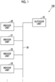
- Fig. 1 is a schematic diagram showing an example of a multi-type air conditioner according to the embodiment.
- the multi-type air conditioner is an air conditioner in which a plurality of indoor units are connected to one outdoor unit.
- An air conditioner 100 in Fig. 1 is a multi-type air conditioning system that includes an outdoor unit 10 and a plurality of indoor units 20, 21, 22, and 23.
- the outdoor unit 10 and each of the indoor units 20 to 23 are connected to each other by a refrigerant pipe 30.
- the number of the outdoor units 10, and the number of the indoor unit 20 and the like are not limited to the number shown in Fig. 1 .
- the number of the indoor unit 20 and the like may be two or three, or five or more.
- the number of outdoor units 10 may be two or more.
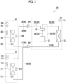
- Fig. 2 shows a schematic diagram of a refrigerant circuit of the multi-type air conditioner 100 in a case where the outdoor unit 10 is one and the indoor unit 20 and the like are two (20, 21).
- the outdoor unit 10 includes a compressor 11, a four-way valve 12, an outdoor heat exchanger 13, and a control device 14.
- the discharge side of the compressor 11 and the four-way valve 12 are connected by a pipe 34
- the four-way valve 12 and the outdoor heat exchanger 13 are connected by a pipe 32
- the four-way valve 12 and the suction side of the compressor 11 are connected by a pipe 33.
- the four-way valve 12 and a joint 3A are connected by a pipe 35.
- the outdoor heat exchanger 13 and a joint 3B are connected by a pipe 31.
- the control device 14 performs control of the compressor 11 or the like.
- the indoor unit 20 includes an indoor heat exchanger 201, an expansion valve 202, a fan 203, a temperature sensor 204, a temperature sensor 205, and a control device 206.
- a pipe 36 connects the joint 3A and the indoor heat exchanger 201.
- a pipe 37 connects the indoor heat exchanger 201 and the joint 3B, and the expansion valve 202 is provided in the pipe 37.
- the fan 203 is provided in the vicinity of a suction port of the indoor unit 20, sucks in the indoor air, and sends the indoor air to the indoor heat exchanger 201.
- the temperature sensor 204 is provided in the vicinity of the suction port of the indoor unit 20 and measures an indoor temperature (the temperature of the sucked air).
- the temperature sensor 205 is provided in the vicinity of the center of the indoor heat exchanger 201, and measures a refrigerant temperature of the indoor heat exchanger 201.
- the temperature measured by the temperature sensor 205 is the same temperature as the air temperature after air conditioning, which is blown into the room from the indoor unit 20.
- the control device 206 controls the fan 203 and the like. Whether to turn to the thermostat OFF or the thermostat ON when the indoor unit 20 is in the heating operation is determined based on a temperature difference between the setting temperature for heating of the indoor unit 20 and the temperature measured by the temperature sensor 204.
- control device 206 determines to turn the heating operation to the thermostat OFF when the temperature measured by the temperature sensor 204 rises by a predetermined value or more above the setting temperature, and determines to turn the heating operation to the thermostat ON when the temperature measured by the temperature sensor 204 falls by a predetermined value or more below the setting temperature for heating.
- the configuration of the indoor unit 21 is the same as that of the indoor unit 20.
- the indoor unit 21 includes an indoor heat exchanger 211, an expansion valve 212, a fan 213, a temperature sensor 214, a temperature sensor 215, and a control device 216.
- a pipe 38 connects the joint 3A and the indoor heat exchanger 211.
- a pipe 39 connects the indoor heat exchanger 211 and the joint 3B, and the expansion valve 212 is provided in the pipe 39.
- the control device 216 controls the fan 213 and the like.
- the four-way valve 12 is set for the heating operation, and the high-temperature and high-pressure gas refrigerant discharged from the compressor 11 is supplied to the indoor heat exchanger 201 of the indoor unit 20 through the pipe 34, the four-way valve 12, and the pipes 35 and 36, and is supplied to the indoor heat exchanger 211 of the indoor unit 21 through the pipes 34, 35, and 38.
- the refrigerant supplied to the indoor heat exchanger 201 is condensed by being heat-exchanged with the air sent by the fan 203, is depressurized by the expansion valve 202, and is supplied to the outdoor heat exchanger 13 through the pipes 37 and 31.
- the refrigerant supplied to the indoor heat exchanger 211 is condensed by being heat-exchanged with the air sent by the fan 213, is depressurized by the expansion valve 212, and is supplied to the outdoor heat exchanger 13 through the pipes 39 and 31.
- the refrigerant supplied to the outdoor heat exchanger 13 is vaporized by heat exchange with the outside air, and the vaporized refrigerant is sucked into the compressor 11 through the pipe 32, the four-way valve 12, and the pipe 33.
- the refrigerant supplied from the outdoor unit 10 is shared by the indoor units 20 and 21.
- the refrigerant is supplied to the indoor heat exchanger 201 (the supply amount is reduced by the control of the expansion valve 202). Therefore, in a case where the refrigerant is excessively accumulated in the indoor heat exchanger 201, the amount of refrigerant that is supplied to the indoor unit 21 is decreased.
- various controls of the expansion valve 202 or the fan 203 are performed.
- the fan 203 is often operated even at the time of the thermostat OFF such that the temperature sensor 204 can measure an accurate indoor temperature.
- the overheating of the room is caused, and the refrigerant condensation in the indoor heat exchanger 201 is promoted. Therefore, it is desirable to stop the fan 203 at the time of the thermostat OFF and to accurately measure the indoor temperature.
- the indoor unit 20 and the outdoor unit 10 are configured to circulate the indoor air by natural convection, instead of operating the fan 203, by utilizing the tendency that warm air heated by the refrigerant supplied to the indoor heat exchanger 201 rises even at the time of the thermostat OFF to stir the indoor air, and to measure the indoor air temperature, which is made uniform as a result, by the temperature sensor 204.
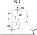
- Fig. 3 schematically shows the configuration of the indoor unit 20 according to the embodiment.
- the indoor unit 20 is a floor-standing indoor unit.
- a suction port 207 for indoor air is provided in a lower portion of the indoor unit 20, and a discharge outlet 208 for air after air conditioning is provided in an upper portion of the indoor unit 20.
- the fan 203 or the temperature sensor 204 is provided near the suction port 207.
- the suction port 207 is provided on a lower side with respect to the center of the indoor heat exchanger 201, and the discharge outlet 208 is provided above the indoor heat exchanger 201.
- the suction port 207, the indoor heat exchanger 201, and the discharge outlet 208 By disposing the suction port 207, the indoor heat exchanger 201, and the discharge outlet 208 in this order from below, when the heating operation of the indoor unit 20 is turned to the thermostat OFF, the air inside the indoor unit 20 is heated by the indoor heat exchanger 201, rises, and is supplied into the room from the discharge outlet 208. The supplied air rises in the room. The indoor air flows into the indoor heat exchanger 201 at a low pressure from the suction port 207, and is supplied into the room from the discharge outlet 208 at the upper portion of the indoor unit 20 through the same process.
- Q is an air supply speed (m 3 /s)
- C is a predetermined flow rate coefficient (for example, a value in a range of 0.65 to 0.7)
- A is a chimney cross-sectional area (m 2 )
- g is a gravitational acceleration
- h is a chimney height (m)
- T1 is an outside air temperature (K)
- T2 is an average temperature in a chimney (K).
- Ao is an area (m 2 ) of the discharge outlet 208
- Ai is an area (m 2 ) of the suction port 207
- C2 is a pressure loss coefficient by the indoor heat exchanger 201 (a reduction rate of a pressure loss due to a heat exchange pressure loss, for example, 0.5)
- g is a gravitational acceleration
- h is a height difference (m) (h shown in Fig. 3 ) between the center in the height direction of the indoor heat exchanger 201 and the discharge outlet 208
- To is a temperature (K) of discharged air
- Ti is a temperature (K) of suction air.
- the value 0.5 m/s of the left side is based on the idea that, since the Building Standards Law stipulates that the indoor airflow must be 0.5 m/s or less, the natural convection will occur in a case where the airflow of 0.5 m/s or more is generated indoors.
- the value of the left side can be set to any value according to the environment in which the indoor unit 20 is installed.
- Ti is the temperature measured by the temperature sensor 204, and To is the same temperature as the temperature measured by the temperature sensor 205.
- the temperature measured by the temperature sensor 205 is the condensation temperature of the indoor heat exchanger 201, and the discharge pressure of the compressor 11 is determined based on the condensation temperature.
- To or the discharge pressure of the compressor 11 necessary for satisfying Expression (2) is determined.
- the multi-type air conditioner 100 it is necessary to decide the operation of the compressor 11 in consideration of the setting temperature of the other indoor unit 21 or the like.
- the control device 14 of the outdoor unit 10 is designed to operate the compressor 11 such that the condensation temperature of the indoor heat exchanger 201 is To satisfying Expression (2).
- the control device 206 of the indoor unit 20 stops the fan 203. Then, in the indoor unit 20, a flow of air in which at a speed that can be calculated by the right side of Expression (2), indoor air is sucked from the suction port 207 and warm air is discharged from the discharge outlet 208 is generated. Since the flow of air satisfies the condition of Expression (2), the flow of air is not affected by the indoor airflow, and natural convection occurs indoors. In a case where the indoor air circulates by natural convection, the indoor air is mixed, so that the indoor temperature is made uniform, and the temperature measured by the temperature sensor 204 is an accurate temperature in the room. In this way, it is possible to detect an accurate indoor temperature without operating the fan 203.
- Expression (3) defines that the heating capacity of the indoor unit 20 when the fan 203 is stopped at the time of the thermostat OFF is set to 50% or less of the rated capacity of the indoor unit 20.
- the value of the left side of Expression (3) can be set to any value. Since the heating capacity is obtained by multiplying the air volume by the temperature difference between the suction port 207 and the discharge outlet 208, the right side of Expression (3) can be obtained from the right side of Expression (2) that defines the suction speed.
- the indoor unit 20 having Ai, Ao, and h that satisfy Expression (3) and operated at the setting temperature Ti and the condensation temperature To is designed.
- the heating capacity at the time of the thermostat OFF can be set to 50% or less of the rated capacity. Since To is a value (for example, 40°C or higher) that is established as the heating operation, it is found that, in a case where Ti and To are designed to satisfy Expression (3), the suction speed at the suction port 207, which can be calculated by the right side of Expression (2), is a speed at which the natural convection occurs.
- the compressor 11 by operating the compressor 11 such that the condensation temperature of the indoor heat exchanger 201 is To with respect to the indoor unit 20 designed based on (3), even in a case where the fan 203 is stopped at the time of the thermostat OFF of the heating operation of the indoor unit 20, the flow of air due to the natural convection occurs, and an accurate indoor temperature can be measured by the temperature sensor 204.
- the heating capacity at the thermostat OFF can be suppressed to be a desired value or less.
- Ti can be regarded as the setting temperature at the time of the heating operation and To can be regarded as the condensation temperature of the indoor heat exchanger at the time of the heating operation
- the values of Ti and To are determined in an approximate range.
- values of h, Ao, and Ai satisfying Expression (2) and Expression (3) are designed, and the indoor unit 20 in which the suction port 207, the indoor heat exchanger 201, and the discharge outlet 208 are disposed in this order from below, as illustrated in Fig. 3 , is designed and manufactured.
- the manufactured indoor unit 20 is installed, and when the thermostat OFF is made during the heating operation, the fan 203 is controlled to be stopped.
- the indoor temperature is made uniform by the natural convection, it is possible to measure an accurate indoor temperature by the temperature sensor 204 provided in the vicinity of the suction port 207.
- the opening portions of the indoor unit 20, which are used for natural convection at the time of the thermostat OFF, are defined as the suction port 207 and the discharge outlet 208.
- opening portions other than the suction port 207 and the discharge outlet 208 may be provided.
- an opening portion 1 for suction and an opening portion 2 for discharge may be provided, and the opening portion 1, the indoor heat exchanger 201, and the opening portion 2 may be disposed in this order from below. Then, at the time of the thermostat OFF of the heating operation, the indoor air may be sucked in by using any one or both of the suction port 207 and the opening portion 1, and the warm air may be discharged by using any one or both of the discharge outlet 208 and the opening portion 2.
- the air conditioner and the control method it is possible to measure the indoor temperature without operating the fan at the time of the thermostat OFF of the heating operation.
Landscapes
- Engineering & Computer Science (AREA)
- Chemical & Material Sciences (AREA)
- Combustion & Propulsion (AREA)
- Mechanical Engineering (AREA)
- General Engineering & Computer Science (AREA)
- Signal Processing (AREA)
- Physics & Mathematics (AREA)
- Fuzzy Systems (AREA)
- Mathematical Physics (AREA)
- Air Conditioning Control Device (AREA)
- Air-Conditioning Room Units, And Self-Contained Units In General (AREA)
Abstract
Description
- The present invention relates to an air conditioner and a control method. The present disclosure claims priority based on
Japanese Patent Application No. 2022-127123 filed in Japan on August 9, 2022 - As shown in
Fig. 1 , amulti-type air conditioner 100 that includes a plurality ofindoor units outdoor unit 10 is provided. In themulti-type air conditioner 100, the refrigerant sent out by theoutdoor unit 10 is shared by theindoor units 20 to 23, and therefore, in a case where the refrigerant is excessively accumulated in an indoor heat exchanger of theindoor unit 20, for example, the amount of the refrigerant that is supplied to theindoor units 21 to 23 is reduced, and the air conditioning capacity of theindoor units 21 to 23 is reduced. For example, in a case where thermostat OFF (the thermostat OFF means that an indoor temperature reaches a setting temperature and an operation state is made in which heat exchange between the refrigerant flowing through the indoor heat exchanger of theindoor unit 20 and the indoor air is unnecessary) is made during the heating operation of theindoor unit 20, the gas refrigerant supplied to the indoor heat exchanger is condensed and liquefied, and the refrigerant is accumulated in the indoor heat exchanger of theindoor unit 20. This is because, in themulti-type air conditioner 100, even in a case where the thermostat OFF is made, the refrigerant is supplied to the indoor heat exchanger and is condensed due to the operation of a fan, or the like. As a measure for preventing the refrigerant from being condensed in the indoor heat exchanger, a method of causing the refrigerant to continuously flow by opening an expansion valve is considered. However, in order to detect an accurate indoor temperature even at the time of the thermostat OFF, it is necessary to operate the fan, and thus the heating operation is actually performed even at the time of the thermostat OFF. As a related technique, PTL 1 discloses a method of installing a temperature sensor such that an indoor temperature can be accurately measured even in a case where a fan is not operated at the time of the thermostat OFF. - [PTL 1]
Japanese Unexamined Patent Application Publication No. 2009-97742 - There is a demand for an air conditioner capable of measuring an indoor temperature without operating a fan even at the time of the thermostat OFF of the heating operation.
- The present disclosure provides an air conditioner and a control method capable of solving the problem described above.
- According to an aspect of the present disclosure, there is provided an air conditioner including: an indoor unit that includes a fan, an indoor heat exchanger, a first opening portion through which air is sucked, a second opening portion through which air is discharged, and a temperature sensor; and an outdoor unit, in which the first opening portion is provided on a lower side with respect to a center in a height direction of the indoor heat exchanger, the second opening portion is provided above the indoor heat exchanger, and based on a predetermined conditional expression that includes an air temperature at the first opening portion during heating operation, an air temperature at the second opening portion, a height difference in the height direction between the center in the height direction of the indoor heat exchanger and the second opening portion, and an area of the second opening portion, the air temperature at the first opening portion, the air temperature at the second opening portion, the height difference in the height direction between the center in the height direction of the indoor heat exchanger and the second opening portion, an area of the first opening portion, and the area of the second opening portion are set such that a flow of air in which the air is sucked in from the first opening portion and the air is discharged from the second opening portion is generated even when the fan is stopped in a case where thermostat OFF in which heat exchange in the indoor heat exchanger is unnecessary is made during the heating operation.
- According to an aspect of the present disclosure, there is provided a control method including: stopping the fan when the heating operation of the indoor unit is turned to the thermostat OFF in the air conditioner described above.
- According to the air conditioner and the control method, it is possible to measure the indoor temperature without operating the fan at the time of the thermostat OFF of the heating operation.
-
-
Fig. 1 is a schematic diagram of a multi-type air conditioner according to an embodiment. -
Fig. 2 is a schematic diagram showing an example of a refrigerant circuit of the multi-type air conditioner according to the embodiment. -
Fig. 3 is a schematic diagram showing an example of an indoor unit according to the embodiment. - Hereinafter, an air conditioner and a control method according to an embodiment of the present disclosure will be described with reference to
Figs. 1 to 3 . -
Fig. 1 is a schematic diagram showing an example of a multi-type air conditioner according to the embodiment. The multi-type air conditioner is an air conditioner in which a plurality of indoor units are connected to one outdoor unit. Anair conditioner 100 inFig. 1 is a multi-type air conditioning system that includes anoutdoor unit 10 and a plurality ofindoor units outdoor unit 10 and each of theindoor units 20 to 23 are connected to each other by arefrigerant pipe 30. The number of theoutdoor units 10, and the number of theindoor unit 20 and the like are not limited to the number shown inFig. 1 . For example, the number of theindoor unit 20 and the like may be two or three, or five or more. The number ofoutdoor units 10 may be two or more. -
Fig. 2 shows a schematic diagram of a refrigerant circuit of themulti-type air conditioner 100 in a case where theoutdoor unit 10 is one and theindoor unit 20 and the like are two (20, 21). As shown inFig. 2 , theoutdoor unit 10 includes acompressor 11, a four-way valve 12, anoutdoor heat exchanger 13, and acontrol device 14. The discharge side of thecompressor 11 and the four-way valve 12 are connected by apipe 34, the four-way valve 12 and theoutdoor heat exchanger 13 are connected by apipe 32, and the four-way valve 12 and the suction side of thecompressor 11 are connected by apipe 33. The four-way valve 12 and ajoint 3A are connected by apipe 35. Theoutdoor heat exchanger 13 and a joint 3B are connected by apipe 31. Thecontrol device 14 performs control of thecompressor 11 or the like. - The
indoor unit 20 includes anindoor heat exchanger 201, anexpansion valve 202, afan 203, atemperature sensor 204, atemperature sensor 205, and acontrol device 206. Apipe 36 connects thejoint 3A and theindoor heat exchanger 201. Apipe 37 connects theindoor heat exchanger 201 and thejoint 3B, and theexpansion valve 202 is provided in thepipe 37. Thefan 203 is provided in the vicinity of a suction port of theindoor unit 20, sucks in the indoor air, and sends the indoor air to theindoor heat exchanger 201. Thetemperature sensor 204 is provided in the vicinity of the suction port of theindoor unit 20 and measures an indoor temperature (the temperature of the sucked air). Thetemperature sensor 205 is provided in the vicinity of the center of theindoor heat exchanger 201, and measures a refrigerant temperature of theindoor heat exchanger 201. The temperature measured by thetemperature sensor 205 is the same temperature as the air temperature after air conditioning, which is blown into the room from theindoor unit 20. Thecontrol device 206 controls thefan 203 and the like. Whether to turn to the thermostat OFF or the thermostat ON when theindoor unit 20 is in the heating operation is determined based on a temperature difference between the setting temperature for heating of theindoor unit 20 and the temperature measured by thetemperature sensor 204. For example, thecontrol device 206 determines to turn the heating operation to the thermostat OFF when the temperature measured by thetemperature sensor 204 rises by a predetermined value or more above the setting temperature, and determines to turn the heating operation to the thermostat ON when the temperature measured by thetemperature sensor 204 falls by a predetermined value or more below the setting temperature for heating. - The configuration of the
indoor unit 21 is the same as that of theindoor unit 20. Theindoor unit 21 includes anindoor heat exchanger 211, anexpansion valve 212, afan 213, a temperature sensor 214, atemperature sensor 215, and acontrol device 216. Apipe 38 connects thejoint 3A and theindoor heat exchanger 211. Apipe 39 connects theindoor heat exchanger 211 and thejoint 3B, and theexpansion valve 212 is provided in thepipe 39. Thecontrol device 216 controls thefan 213 and the like. - In a case where the heating operation is performed by the
multi-type air conditioner 100, the four-way valve 12 is set for the heating operation, and the high-temperature and high-pressure gas refrigerant discharged from thecompressor 11 is supplied to theindoor heat exchanger 201 of theindoor unit 20 through thepipe 34, the four-way valve 12, and thepipes indoor heat exchanger 211 of theindoor unit 21 through thepipes indoor heat exchanger 201 is condensed by being heat-exchanged with the air sent by thefan 203, is depressurized by theexpansion valve 202, and is supplied to theoutdoor heat exchanger 13 through thepipes indoor unit 21, the refrigerant supplied to theindoor heat exchanger 211 is condensed by being heat-exchanged with the air sent by thefan 213, is depressurized by theexpansion valve 212, and is supplied to theoutdoor heat exchanger 13 through thepipes outdoor heat exchanger 13 is vaporized by heat exchange with the outside air, and the vaporized refrigerant is sucked into thecompressor 11 through thepipe 32, the four-way valve 12, and thepipe 33. - As described with reference to
Fig. 2 , in themulti-type air conditioner 100, the refrigerant supplied from theoutdoor unit 10 is shared by theindoor units multi-type air conditioner 100, even in a case where the heating operation of theindoor unit 20 is turned to the thermostat OFF, the refrigerant is supplied to the indoor heat exchanger 201 (the supply amount is reduced by the control of the expansion valve 202). Therefore, in a case where the refrigerant is excessively accumulated in theindoor heat exchanger 201, the amount of refrigerant that is supplied to theindoor unit 21 is decreased. In order to prevent the refrigerant from being accumulated in theindoor heat exchanger 201, various controls of theexpansion valve 202 or thefan 203 are performed. However, thefan 203 is often operated even at the time of the thermostat OFF such that thetemperature sensor 204 can measure an accurate indoor temperature. In a case where thefan 203 is operated at the time of the thermostat OFF, the overheating of the room is caused, and the refrigerant condensation in theindoor heat exchanger 201 is promoted. Therefore, it is desirable to stop thefan 203 at the time of the thermostat OFF and to accurately measure the indoor temperature. Therefore, in the present embodiment, theindoor unit 20 and theoutdoor unit 10 are configured to circulate the indoor air by natural convection, instead of operating thefan 203, by utilizing the tendency that warm air heated by the refrigerant supplied to theindoor heat exchanger 201 rises even at the time of the thermostat OFF to stir the indoor air, and to measure the indoor air temperature, which is made uniform as a result, by thetemperature sensor 204. -
Fig. 3 schematically shows the configuration of theindoor unit 20 according to the embodiment. Theindoor unit 20 is a floor-standing indoor unit. Asuction port 207 for indoor air is provided in a lower portion of theindoor unit 20, and adischarge outlet 208 for air after air conditioning is provided in an upper portion of theindoor unit 20. Thefan 203 or thetemperature sensor 204 is provided near thesuction port 207. Thesuction port 207 is provided on a lower side with respect to the center of theindoor heat exchanger 201, and thedischarge outlet 208 is provided above theindoor heat exchanger 201. By disposing thesuction port 207, theindoor heat exchanger 201, and thedischarge outlet 208 in this order from below, when the heating operation of theindoor unit 20 is turned to the thermostat OFF, the air inside theindoor unit 20 is heated by theindoor heat exchanger 201, rises, and is supplied into the room from thedischarge outlet 208. The supplied air rises in the room. The indoor air flows into theindoor heat exchanger 201 at a low pressure from thesuction port 207, and is supplied into the room from thedischarge outlet 208 at the upper portion of theindoor unit 20 through the same process. - In this case, in order to generate the natural convection, it is necessary to generate a flow stronger than the airflow already present in the room. Here, the following calculation expression (1) for calculating an air supply speed of a gas flowing into a chimney, based on a chimney effect, is adopted.

- Q is an air supply speed (m3/s), C is a predetermined flow rate coefficient (for example, a value in a range of 0.65 to 0.7), A is a chimney cross-sectional area (m2), g is a gravitational acceleration, h is a chimney height (m), T1 is an outside air temperature (K), and T2 is an average temperature in a chimney (K).
- In a case where Expression (1) is applied to the
indoor unit 20 ofFig. 3 , the right side of the following expression (2) is obtained by regarding an air flow path from a center L in the height direction of theindoor heat exchanger 201 of theindoor unit 20 to thedischarge outlet 208 as a chimney. The suction speed of the indoor air that is sucked into theindoor unit 20 can be calculated by the right side of Expression (2).
- Ao is an area (m2) of the
discharge outlet 208, Ai is an area (m2) of thesuction port 207, C2 is a pressure loss coefficient by the indoor heat exchanger 201 (a reduction rate of a pressure loss due to a heat exchange pressure loss, for example, 0.5), g is a gravitational acceleration, h is a height difference (m) (h shown inFig. 3 ) between the center in the height direction of theindoor heat exchanger 201 and thedischarge outlet 208, To is a temperature (K) of discharged air, and Ti is a temperature (K) of suction air. - The value 0.5 m/s of the left side is based on the idea that, since the Building Standards Law stipulates that the indoor airflow must be 0.5 m/s or less, the natural convection will occur in a case where the airflow of 0.5 m/s or more is generated indoors. The value of the left side can be set to any value according to the environment in which the
indoor unit 20 is installed. Ti is the temperature measured by thetemperature sensor 204, and To is the same temperature as the temperature measured by thetemperature sensor 205. The temperature measured by thetemperature sensor 205 is the condensation temperature of theindoor heat exchanger 201, and the discharge pressure of thecompressor 11 is determined based on the condensation temperature. For example, in a case where Ti is set as the setting temperature, To or the discharge pressure of thecompressor 11 necessary for satisfying Expression (2) is determined. In themulti-type air conditioner 100, it is necessary to decide the operation of thecompressor 11 in consideration of the setting temperature of the otherindoor unit 21 or the like. However, it is possible to design h, Ao, Ai, To at the time of heating, the discharge pressure of thecompressor 11, and the like in advance to satisfy Expression (2) even in consideration of the setting temperature of the otherindoor unit 21 or the like. Thecontrol device 14 of theoutdoor unit 10 is designed to operate thecompressor 11 such that the condensation temperature of theindoor heat exchanger 201 is To satisfying Expression (2). Then, when theindoor unit 20 is in the thermostat OFF during the heating operation, thecontrol device 206 of theindoor unit 20 stops thefan 203. Then, in theindoor unit 20, a flow of air in which at a speed that can be calculated by the right side of Expression (2), indoor air is sucked from thesuction port 207 and warm air is discharged from thedischarge outlet 208 is generated. Since the flow of air satisfies the condition of Expression (2), the flow of air is not affected by the indoor airflow, and natural convection occurs indoors. In a case where the indoor air circulates by natural convection, the indoor air is mixed, so that the indoor temperature is made uniform, and the temperature measured by thetemperature sensor 204 is an accurate temperature in the room. In this way, it is possible to detect an accurate indoor temperature without operating thefan 203. - In a case where the
fan 203 is operated at the time of the thermostat OFF of the heating operation as in the control in the related art, it is noted that the room to be air-conditioned by theindoor unit 20 is excessively heated. From the viewpoint of the heating capacity of theindoor unit 20 at the time of the thermostat OFF, a condition for making the heating capacity of theindoor unit 20 at the time of the thermostat OFF appropriate (for example, not excessively heated) may be set, and To and the like may be calculated. Specifically, the following expression (3) which is application of Expression (2) described above can be used.
- Cp is the specific heat of air. Ao, C2, g, h, Ti, and To are the same as in Expression (2). Expression (3) defines that the heating capacity of the
indoor unit 20 when thefan 203 is stopped at the time of the thermostat OFF is set to 50% or less of the rated capacity of theindoor unit 20. The value of the left side of Expression (3) can be set to any value. Since the heating capacity is obtained by multiplying the air volume by the temperature difference between thesuction port 207 and thedischarge outlet 208, the right side of Expression (3) can be obtained from the right side of Expression (2) that defines the suction speed. Theindoor unit 20 having Ai, Ao, and h that satisfy Expression (3) and operated at the setting temperature Ti and the condensation temperature To is designed. In this way, the heating capacity at the time of the thermostat OFF can be set to 50% or less of the rated capacity. Since To is a value (for example, 40°C or higher) that is established as the heating operation, it is found that, in a case where Ti and To are designed to satisfy Expression (3), the suction speed at thesuction port 207, which can be calculated by the right side of Expression (2), is a speed at which the natural convection occurs. Accordingly, by operating thecompressor 11 such that the condensation temperature of theindoor heat exchanger 201 is To with respect to theindoor unit 20 designed based on (3), even in a case where thefan 203 is stopped at the time of the thermostat OFF of the heating operation of theindoor unit 20, the flow of air due to the natural convection occurs, and an accurate indoor temperature can be measured by thetemperature sensor 204. The heating capacity at the thermostat OFF can be suppressed to be a desired value or less. - As described above, since Ti can be regarded as the setting temperature at the time of the heating operation and To can be regarded as the condensation temperature of the indoor heat exchanger at the time of the heating operation, the values of Ti and To are determined in an approximate range. By using this, values of h, Ao, and Ai satisfying Expression (2) and Expression (3) are designed, and the
indoor unit 20 in which thesuction port 207, theindoor heat exchanger 201, and thedischarge outlet 208 are disposed in this order from below, as illustrated inFig. 3 , is designed and manufactured. Then, the manufacturedindoor unit 20 is installed, and when the thermostat OFF is made during the heating operation, thefan 203 is controlled to be stopped. Then, since the indoor temperature is made uniform by the natural convection, it is possible to measure an accurate indoor temperature by thetemperature sensor 204 provided in the vicinity of thesuction port 207. - As described above, according to the present embodiment, even when the
fan 203 is stopped at the time of the thermostat OFF of the heating operation of theindoor unit 20 designed based on Expression (2) and/or Expression (3), it is possible to measure an accurate indoor temperature by thetemperature sensor 204. By stopping thefan 203, it is possible to prevent the overheating of the room at the time of the thermostat OFF. By stopping thefan 203, it is possible to reduce the amount of refrigerant that is condensed in theindoor heat exchanger 201 and to suppress the accumulation of the refrigerant in theindoor heat exchanger 201. Therefore, it is possible to prevent occurrence of a decrease in heating capacity due to a shortage of a refrigerant in the otherindoor units 21 and the like. - In the embodiment described above, the opening portions of the
indoor unit 20, which are used for natural convection at the time of the thermostat OFF, are defined as thesuction port 207 and thedischarge outlet 208. However, opening portions other than thesuction port 207 and thedischarge outlet 208 may be provided. For example, an opening portion 1 for suction and an opening portion 2 for discharge may be provided, and the opening portion 1, theindoor heat exchanger 201, and the opening portion 2 may be disposed in this order from below. Then, at the time of the thermostat OFF of the heating operation, the indoor air may be sucked in by using any one or both of thesuction port 207 and the opening portion 1, and the warm air may be discharged by using any one or both of thedischarge outlet 208 and the opening portion 2. - In addition, it is possible to appropriately replace the constituent elements in the embodiment described above with well-known constituent elements within a scope that does not depart from the gist of the present invention. The scope of the present invention is not limited to the above-mentioned embodiment, and the present invention can include various changes without departing from the scope of the present invention. For example, Ti, To, h, Ai, and Ao may be designed such that both of Expression (2) and Expression (3) are satisfied.
- The air conditioner and the control method described in each embodiment are understood, for example, as follows.
-
- (1) The air conditioner 100 according to a first aspect includes: an indoor unit that includes a fan, an indoor heat exchanger, a first opening portion through which air is sucked, a second opening portion through which air is discharged, and a temperature sensor; and an outdoor unit, in which the first opening portion is provided on a lower side with respect to a center in a height direction of the indoor heat exchanger, the second opening portion is provided above the indoor heat exchanger, and in order to satisfy a predetermined conditional expression that includes an air temperature at the first opening portion and an air temperature at the second opening portion during heating operation, a height difference in the height direction between the center in the height direction of the indoor heat exchanger and the second opening portion, and an area of the second opening portion, the air temperature at the first opening portion, the air temperature at the second opening portion, the height difference in the height direction between the center in the height direction of the indoor heat exchanger and the second opening portion, an area of the first opening portion, and the area of the second opening portion are set such that a flow of air in which the air is sucked in from the first opening portion and the air is discharged from the second opening portion is generated even when the fan is stopped in a case where thermostat OFF in which heat exchange in the indoor heat exchanger is unnecessary is made during the heating operation.
By configuring the air conditioner in this way, even when the fan is stopped at the time of the thermostat OFF of the heating operation, the indoor temperature is made uniform by natural convection, so that an accurate indoor temperature can be measured. - (2) In the
air conditioner 100 according to a second aspect, in theair conditioner 100 of the above (1), when the air temperature at the first opening portion is set to be Ti, the air temperature at the second opening portion is set to be To, the height difference in the height direction between the center in the height direction of the indoor heat exchanger and the second opening portion is set to be h, the area of the first opening portion is set to be Ai, the area of the second opening portion is set to be Ao, and C2 is a pressure loss coefficient of the indoor heat exchanger, the conditional expression is a following expression.
- (3) In the
air conditioner 100 according to a third aspect, in the air conditioner of the above (1) or (2), when the air temperature at the first opening portion is set to be Ti, the air temperature at the second opening portion is set to be To, the height difference in the height direction between the center in the height direction of the indoor heat exchanger and the second opening portion is set to be h, the area of the second opening portion is set to be Ao, C2 is a pressure loss coefficient of the indoor heat exchanger, and Cp is a specific heat of air, the conditional expression is a following expression.
- (4) In the
air conditioner 100 according to a fourth aspect, in the air conditioner of any one of the above (1) to (3), a plurality of the indoor units and the outdoor unit are provided, the plurality of indoor units and the outdoor unit are connected by a refrigerant pipe, and a refrigerant flows through the indoor heat exchanger even when the heating operation of the indoor unit having the indoor heat exchanger is in the thermostat OFF.
The indoor unit satisfying the conditional expression of the present embodiment is suitable for an indoor unit of a multi-type air conditioner. - (5) A control method according to a fifth aspect includes: stopping the fan when the heating operation of the indoor unit is turned to the thermostat OFF in the air conditioner of any one of the above (1) to (4).
- In this way, it is possible to prevent the overheating of the room by the indoor unit that is in the thermostat OFF, the refrigerant accumulation in the indoor heat exchanger of the indoor unit, and the insufficient heating capacity in the other indoor unit.
- According to the air conditioner and the control method, it is possible to measure the indoor temperature without operating the fan at the time of the thermostat OFF of the heating operation.
-
- 10: outdoor unit
- 11: compressor
- 12: four-way valve
- 13: outdoor heat exchanger
- 14: control device
- 20: indoor unit
- 201: indoor heat exchanger
- 202: expansion valve
- 203: fan
- 204: temperature sensor
- 205: temperature sensor
- 206: control device
- 21: indoor unit
- 211: indoor heat exchanger
- 212: expansion valve
- 213: fan
- 214: temperature sensor
- 215: temperature sensor
- 216: control device
- 22: indoor unit
- 23: indoor unit
- 30 to 39: pipe
- 3A, 3B: joint
Claims (5)
- An air conditioner comprising:an indoor unit that includes a fan, an indoor heat exchanger, a first opening portion through which air is sucked, a second opening portion through which air is discharged, and a temperature sensor; andan outdoor unit,wherein the first opening portion is provided on a lower side with respect to a center in a height direction of the indoor heat exchanger,the second opening portion is provided above the indoor heat exchanger, andin order to satisfy a predetermined conditional expression that includes an air temperature at the first opening portion and an air temperature at the second opening portion during heating operation, a height difference in the height direction between the center in the height direction of the indoor heat exchanger and the second opening portion, and an area of the second opening portion, the air temperature at the first opening portion, the air temperature at the second opening portion, the height difference in the height direction between the center in the height direction of the indoor heat exchanger and the second opening portion, an area of the first opening portion, and the area of the second opening portion are set such that a flow of air in which the air is sucked in from the first opening portion and the air is discharged from the second opening portion is generated even when the fan is stopped in a case where thermostat OFF in which heat exchange in the indoor heat exchanger is unnecessary is made during the heating operation.
- The air conditioner according to Claim 1,
wherein when the air temperature at the first opening portion is set to be Ti, the air temperature at the second opening portion is set to be To, the height difference in the height direction between the center in the height direction of the indoor heat exchanger and the second opening portion is set to be h, the area of the first opening portion is set to be Ai, the area of the second opening portion is set to be Ao, g is a gravitational acceleration, and C2 is a pressure loss coefficient of the indoor heat exchanger, the conditional expression is a following expression.
- The air conditioner according to Claim 1 or 2,
wherein when the air temperature at the first opening portion is set to be Ti, the air temperature at the second opening portion is set to be To, the height difference in the height direction between the center in the height direction of the indoor heat exchanger and the second opening portion is set to be h, the area of the second opening portion is set to be Ao, C2 is a pressure loss coefficient of the indoor heat exchanger, g is a gravitational acceleration, and Cp is a specific heat of air, the conditional expression is a following expression.
- The air conditioner according to Claim 1 or 2,
wherein a plurality of the indoor units and the outdoor unit are provided, the plurality of indoor units and the outdoor unit are connected by a refrigerant pipe, and a refrigerant flows through the indoor heat exchanger even when the heating operation of the indoor unit having the indoor heat exchanger is in the thermostat OFF. - A control method comprising:
stopping the fan when the heating operation of the indoor unit is turned to the thermostat OFF in the air conditioner according to Claim 1 or 2.
Applications Claiming Priority (2)
| Application Number | Priority Date | Filing Date | Title |
|---|---|---|---|
| JP2022127123A JP2024024350A (en) | 2022-08-09 | 2022-08-09 | Air conditioner and control method |
| PCT/JP2023/026034 WO2024034328A1 (en) | 2022-08-09 | 2023-07-14 | Air conditioner and control method |
Publications (2)
| Publication Number | Publication Date |
|---|---|
| EP4553398A1 true EP4553398A1 (en) | 2025-05-14 |
| EP4553398A4 EP4553398A4 (en) | 2025-07-09 |
Family
ID=89851462
Family Applications (1)
| Application Number | Title | Priority Date | Filing Date |
|---|---|---|---|
| EP23852309.6A Pending EP4553398A4 (en) | 2022-08-09 | 2023-07-14 | AIR CONDITIONING AND CONTROL METHODS |
Country Status (3)
| Country | Link |
|---|---|
| EP (1) | EP4553398A4 (en) |
| JP (1) | JP2024024350A (en) |
| WO (1) | WO2024034328A1 (en) |
Family Cites Families (8)
| Publication number | Priority date | Publication date | Assignee | Title |
|---|---|---|---|---|
| JPH11101495A (en) * | 1997-09-29 | 1999-04-13 | Mitsubishi Heavy Ind Ltd | Fan control method and device for multi-room air conditioner |
| JP2009097742A (en) | 2007-10-15 | 2009-05-07 | Panasonic Corp | Multi-room air conditioner |
| JP5916488B2 (en) * | 2012-04-06 | 2016-05-11 | 三菱重工業株式会社 | Control apparatus and method, program, and multi-type air conditioning system including the same |
| KR102136647B1 (en) * | 2013-06-10 | 2020-07-22 | 삼성전자주식회사 | Air conditional and method for controlling the same |
| WO2016151641A1 (en) * | 2015-03-26 | 2016-09-29 | 三菱電機株式会社 | Indoor unit of air conditioner |
| JP2017110856A (en) * | 2015-12-16 | 2017-06-22 | 株式会社富士通ゼネラル | Air conditioning device |
| CN113614459A (en) * | 2020-03-05 | 2021-11-05 | 日立江森自控空调有限公司 | Air conditioner |
| JP7521453B2 (en) | 2021-02-19 | 2024-07-24 | トヨタ自動車株式会社 | Shelf inventory management system, shelf inventory management method, and program |
-
2022
- 2022-08-09 JP JP2022127123A patent/JP2024024350A/en active Pending
-
2023
- 2023-07-14 WO PCT/JP2023/026034 patent/WO2024034328A1/en not_active Ceased
- 2023-07-14 EP EP23852309.6A patent/EP4553398A4/en active Pending
Also Published As
| Publication number | Publication date |
|---|---|
| WO2024034328A1 (en) | 2024-02-15 |
| JP2024024350A (en) | 2024-02-22 |
| EP4553398A4 (en) | 2025-07-09 |
Similar Documents
| Publication | Publication Date | Title |
|---|---|---|
| EP2320169B1 (en) | Air conditioner and method for determining the amount of refrigerant therein | |
| US8919139B2 (en) | Air conditioning apparatus | |
| JP4245064B2 (en) | Air conditioner | |
| EP2236960B1 (en) | Air conditioner and method of determining amount of refrigerant | |
| US11125473B2 (en) | Air conditioner | |
| EP2314958A1 (en) | Method for judging amount of refrigerant of air conditioner and air conditioner | |
| KR101070186B1 (en) | Direct expansion type air conditioner with automatic blower air flow control device according to refrigerant flow rate change | |
| JP2015059691A (en) | Air conditioner and air conditioning system | |
| EP3839366B1 (en) | Air conditioning device for controlling rotation speed of blower fan | |
| CN107208954B (en) | Air conditioner | |
| CN104364589A (en) | freezer | |
| JP6661775B2 (en) | Air conditioner | |
| JP6503246B2 (en) | Control device of heat source machine for air handling unit | |
| JP2017215116A (en) | Air conditioner | |
| AU2013200092B2 (en) | Air conditioning apparatus and air conditioning apparatus refrigerant quantity determination method | |
| EP3943824B1 (en) | Device evaluation system and device evaluation method | |
| KR101029988B1 (en) | Automatic control of blower air volume according to the change of refrigerant flow rate in the direct expansion type air conditioner | |
| JP2017215115A (en) | Air conditioning device | |
| US11965665B2 (en) | Air conditioning system | |
| EP3650770A1 (en) | Refrigeration cycle device | |
| EP3165846B1 (en) | Refrigerating and air-conditioning apparatus | |
| US12000636B2 (en) | Liquid level detector and air conditioning apparatus including the liquid level detector | |
| WO2024034328A1 (en) | Air conditioner and control method | |
| JP4910577B2 (en) | Reverse phase detection device, air conditioner including the same, and reverse phase detection method | |
| EP4641116A1 (en) | Air conditioner and control method |
Legal Events
| Date | Code | Title | Description |
|---|---|---|---|
| STAA | Information on the status of an ep patent application or granted ep patent |
Free format text: STATUS: THE INTERNATIONAL PUBLICATION HAS BEEN MADE |
|
| PUAI | Public reference made under article 153(3) epc to a published international application that has entered the european phase |
Free format text: ORIGINAL CODE: 0009012 |
|
| STAA | Information on the status of an ep patent application or granted ep patent |
Free format text: STATUS: REQUEST FOR EXAMINATION WAS MADE |
|
| 17P | Request for examination filed |
Effective date: 20250204 |
|
| AK | Designated contracting states |
Kind code of ref document: A1 Designated state(s): AL AT BE BG CH CY CZ DE DK EE ES FI FR GB GR HR HU IE IS IT LI LT LU LV MC ME MK MT NL NO PL PT RO RS SE SI SK SM TR |
|
| A4 | Supplementary search report drawn up and despatched |
Effective date: 20250611 |
|
| RIC1 | Information provided on ipc code assigned before grant |
Ipc: F24F 1/0011 20190101ALI20250604BHEP Ipc: F24F 11/89 20180101ALI20250604BHEP Ipc: F24F 11/74 20180101AFI20250604BHEP |
|
| DAV | Request for validation of the european patent (deleted) | ||
| DAX | Request for extension of the european patent (deleted) |