EP4553300A2 - Strut microtube counterflow evaporator - Google Patents
Strut microtube counterflow evaporator Download PDFInfo
- Publication number
- EP4553300A2 EP4553300A2 EP24199055.5A EP24199055A EP4553300A2 EP 4553300 A2 EP4553300 A2 EP 4553300A2 EP 24199055 A EP24199055 A EP 24199055A EP 4553300 A2 EP4553300 A2 EP 4553300A2
- Authority
- EP
- European Patent Office
- Prior art keywords
- flow
- exhaust gas
- gas flow
- heat exchanger
- recited
- Prior art date
- Legal status (The legal status is an assumption and is not a legal conclusion. Google has not performed a legal analysis and makes no representation as to the accuracy of the status listed.)
- Pending
Links
Images
Classifications
-
- F—MECHANICAL ENGINEERING; LIGHTING; HEATING; WEAPONS; BLASTING
- F02—COMBUSTION ENGINES; HOT-GAS OR COMBUSTION-PRODUCT ENGINE PLANTS
- F02C—GAS-TURBINE PLANTS; AIR INTAKES FOR JET-PROPULSION PLANTS; CONTROLLING FUEL SUPPLY IN AIR-BREATHING JET-PROPULSION PLANTS
- F02C3/00—Gas-turbine plants characterised by the use of combustion products as the working fluid
- F02C3/20—Gas-turbine plants characterised by the use of combustion products as the working fluid using a special fuel, oxidant, or dilution fluid to generate the combustion products
- F02C3/22—Gas-turbine plants characterised by the use of combustion products as the working fluid using a special fuel, oxidant, or dilution fluid to generate the combustion products the fuel or oxidant being gaseous at standard temperature and pressure
-
- F—MECHANICAL ENGINEERING; LIGHTING; HEATING; WEAPONS; BLASTING
- F02—COMBUSTION ENGINES; HOT-GAS OR COMBUSTION-PRODUCT ENGINE PLANTS
- F02C—GAS-TURBINE PLANTS; AIR INTAKES FOR JET-PROPULSION PLANTS; CONTROLLING FUEL SUPPLY IN AIR-BREATHING JET-PROPULSION PLANTS
- F02C7/00—Features, components parts, details or accessories, not provided for in, or of interest apart form groups F02C1/00 - F02C6/00; Air intakes for jet-propulsion plants
- F02C7/08—Heating air supply before combustion, e.g. by exhaust gases
- F02C7/10—Heating air supply before combustion, e.g. by exhaust gases by means of regenerative heat-exchangers
-
- F—MECHANICAL ENGINEERING; LIGHTING; HEATING; WEAPONS; BLASTING
- F02—COMBUSTION ENGINES; HOT-GAS OR COMBUSTION-PRODUCT ENGINE PLANTS
- F02C—GAS-TURBINE PLANTS; AIR INTAKES FOR JET-PROPULSION PLANTS; CONTROLLING FUEL SUPPLY IN AIR-BREATHING JET-PROPULSION PLANTS
- F02C3/00—Gas-turbine plants characterised by the use of combustion products as the working fluid
- F02C3/20—Gas-turbine plants characterised by the use of combustion products as the working fluid using a special fuel, oxidant, or dilution fluid to generate the combustion products
- F02C3/30—Adding water, steam or other fluids for influencing combustion, e.g. to obtain cleaner exhaust gases
- F02C3/305—Increasing the power, speed, torque or efficiency of a gas turbine or the thrust of a turbojet engine by injecting or adding water, steam or other fluids
-
- F—MECHANICAL ENGINEERING; LIGHTING; HEATING; WEAPONS; BLASTING
- F02—COMBUSTION ENGINES; HOT-GAS OR COMBUSTION-PRODUCT ENGINE PLANTS
- F02C—GAS-TURBINE PLANTS; AIR INTAKES FOR JET-PROPULSION PLANTS; CONTROLLING FUEL SUPPLY IN AIR-BREATHING JET-PROPULSION PLANTS
- F02C3/00—Gas-turbine plants characterised by the use of combustion products as the working fluid
- F02C3/34—Gas-turbine plants characterised by the use of combustion products as the working fluid with recycling of part of the working fluid, i.e. semi-closed cycles with combustion products in the closed part of the cycle
-
- F—MECHANICAL ENGINEERING; LIGHTING; HEATING; WEAPONS; BLASTING
- F02—COMBUSTION ENGINES; HOT-GAS OR COMBUSTION-PRODUCT ENGINE PLANTS
- F02C—GAS-TURBINE PLANTS; AIR INTAKES FOR JET-PROPULSION PLANTS; CONTROLLING FUEL SUPPLY IN AIR-BREATHING JET-PROPULSION PLANTS
- F02C7/00—Features, components parts, details or accessories, not provided for in, or of interest apart form groups F02C1/00 - F02C6/00; Air intakes for jet-propulsion plants
- F02C7/12—Cooling of plants
- F02C7/14—Cooling of plants of fluids in the plant, e.g. lubricant or fuel
-
- F—MECHANICAL ENGINEERING; LIGHTING; HEATING; WEAPONS; BLASTING
- F28—HEAT EXCHANGE IN GENERAL
- F28D—HEAT-EXCHANGE APPARATUS, NOT PROVIDED FOR IN ANOTHER SUBCLASS, IN WHICH THE HEAT-EXCHANGE MEDIA DO NOT COME INTO DIRECT CONTACT
- F28D7/00—Heat-exchange apparatus having stationary tubular conduit assemblies for both heat-exchange media, the media being in contact with different sides of a conduit wall
- F28D7/16—Heat-exchange apparatus having stationary tubular conduit assemblies for both heat-exchange media, the media being in contact with different sides of a conduit wall the conduits being arranged in parallel spaced relation
-
- F—MECHANICAL ENGINEERING; LIGHTING; HEATING; WEAPONS; BLASTING
- F05—INDEXING SCHEMES RELATING TO ENGINES OR PUMPS IN VARIOUS SUBCLASSES OF CLASSES F01-F04
- F05D—INDEXING SCHEME FOR ASPECTS RELATING TO NON-POSITIVE-DISPLACEMENT MACHINES OR ENGINES, GAS-TURBINES OR JET-PROPULSION PLANTS
- F05D2260/00—Function
- F05D2260/20—Heat transfer, e.g. cooling
- F05D2260/213—Heat transfer, e.g. cooling by the provision of a heat exchanger within the cooling circuit
-
- F—MECHANICAL ENGINEERING; LIGHTING; HEATING; WEAPONS; BLASTING
- F05—INDEXING SCHEMES RELATING TO ENGINES OR PUMPS IN VARIOUS SUBCLASSES OF CLASSES F01-F04
- F05D—INDEXING SCHEME FOR ASPECTS RELATING TO NON-POSITIVE-DISPLACEMENT MACHINES OR ENGINES, GAS-TURBINES OR JET-PROPULSION PLANTS
- F05D2260/00—Function
- F05D2260/20—Heat transfer, e.g. cooling
- F05D2260/221—Improvement of heat transfer
-
- F—MECHANICAL ENGINEERING; LIGHTING; HEATING; WEAPONS; BLASTING
- F28—HEAT EXCHANGE IN GENERAL
- F28D—HEAT-EXCHANGE APPARATUS, NOT PROVIDED FOR IN ANOTHER SUBCLASS, IN WHICH THE HEAT-EXCHANGE MEDIA DO NOT COME INTO DIRECT CONTACT
- F28D21/00—Heat-exchange apparatus not covered by any of the groups F28D1/00 - F28D20/00
- F28D2021/0019—Other heat exchangers for particular applications; Heat exchange systems not otherwise provided for
- F28D2021/0021—Other heat exchangers for particular applications; Heat exchange systems not otherwise provided for for aircrafts or cosmonautics
Definitions
- the present disclosure relates generally to an aircraft propulsion system that includes a strut mounted heat exchanger where thermal energy is communicated between different flows.
- Turbine engines compress incoming core airflow, mix the compressed airflow with fuel that is ignited in a combustor to generate an exhaust gas flow.
- Steam injection can provide improved operating efficiencies.
- Water recovered from the exhaust gas flow may be transformed into steam using thermal energy from the exhaust gas flow.
- Water recovery and steam generation utilize ducting and heat exchangers exposed to the high temperatures of the exhaust gas. The efficient transfer of thermal energy within heat exchangers may require large surfaces areas that present challenges for implementation as part of an aircraft engine architectures.
- An aircraft propulsion system includes, among other possible things, a core engine section that defines a core flow path where an inlet airflow is compressed, mixed with fuel, and ignited to generate an exhaust gas flow, an inner nacelle assembly that surrounds the core engine section, an outer nacelle assembly that is spaced radially apart from the inner nacelle assembly, and a strut heat exchanger that extends radially between the inner nacelle assembly and the outer nacelle assembly, wherein within the strut heat exchanger a portion of the exhaust gas flow is placed in thermal communication with a second flow for transferring thermal energy.
- the strut heat exchanger includes an outer fairing assembly that defines an outer surface that extends between a leading edge, a trailing edge, a radially inner end at the inner nacelle assembly and a radially outer end at the outer nacelle assembly.
- the strut heat exchanger includes an inner cavity that extends between an inner opening open through the inner nacelle assembly and an outer opening that is open into the outer nacelle assembly, and a plurality of tube assemblies that extend through the inner cavity between the inner nacelle assembly and the outer nacelle assembly.
- the portion of the exhaust gas flow is communicated through the inner cavity and the second flow is communicated through at least one of the plurality of tube assemblies.
- the plurality of tube assemblies include a plurality of micro-tubes that are supported by at least one support member.
- the support member includes a turbulator for disrupting laminar flow adjacent to the plurality of tube assemblies.
- the outer fairing assembly includes a first fairing and a second fairing that are attachable to each other.
- the portion of the exhaust gas flow flows through the inner cavity in a first radial direction and the second flow flows through the plurality of tubes in a second radial direction counter to the first radial direction.
- the aircraft propulsion system further includes a condenser where water is extracted from the exhaust gas flow and an evaporator system where thermal energy from the exhaust gas flow is utilized to generate a steam flow from at least a portion of water that is extracted by the condenser for injection into the core flow path.
- the second flow includes a flow of water and at least a portion of thermal energy from the exhaust gas flow is communicated to the water flow within the strut heat exchanger.
- a portion of the condenser is disposed within the outer nacelle.
- a heat exchanger for an aircraft propulsion system includes, among other possible things, an outer fairing assembly that defines an outer surface that extends between a leading edge, a trailing edge, a radially inner end, and a radially outer end, an inner cavity that is defined within the outer fairing that defines a first flow path that extends between an inner opening that is disposed at the radially inner end and an outer opening that is disposed at the radially outer end, and a plurality of tube assemblies that extend through the inner cavity that define a second flow path between the inner end and the outer end.
- the first flow path and the second flow path are configured to transfer thermal energy between flows within the first flow path and the second flow path.
- the plurality of tube assemblies include a plurality of micro-tubes that are supported by at least one support member.
- the support member includes a turbulator for disrupting laminar flow adjacent to the plurality of tube assemblies.
- the inner cavity is configured to receive a portion of an exhaust gas flow that is generated by the aircraft propulsion system.
- each of the plurality of tube assemblies are configured to receive a portion of a flow that accepts thermal energy from the exhaust gas flow.
- the outer fairing assembly includes a first fairing and a second fairing that are attachable to each other.
- a method of operating a gas turbine engine includes, among other possible things, generating an exhaust gas flow, routing a portion of the exhaust gas flow through an inner cavity of a strut heat exchanger, extracting water from the exhaust gas flow in a condenser, routing a flow of extracted water through a plurality of tubes that extend through the strut heat exchanger that is in thermal communication with the exhaust gas flow, and generating a steam flow by heating the portion of the flow of extracted water with heat from the exhaust gas flow within the strut heat exchanger.
- a portion of the condenser is disposed within an outer nacelle and the method includes routing a portion of the exhaust gas flow through the condenser within the nacelle.
- the method further includes directing the portion of exhaust gas flow through the inner cavity in a first radial direction and directing the flow of extracted water through the plurality of tubes in a second radial direction that is counter to the first radial direction.
- the method further includes disrupting laminar flow of the exhaust gas flow with turbulators that are disposed on structures that support the plurality of tubes.
- Figure 1 schematically illustrates an example propulsion system 20 that includes a strut heat exchanger 56 disposed between an inner nacelle 44 and an outer nacelle.
- the strut heat exchanger 56 includes an inner cavity within which thermal energy is transferred between different flows.
- the example propulsion system 20 includes a fan section 24 and a core engine section 22.
- the core engine section 22 includes a compressor section 26, a combustor section 28 and the turbine section 30 disposed along an engine longitudinal axis A.
- the fan section 24 drives inlet airflow as bypass airflow 58 along a bypass flow path B, while the compressor section 26 draws air in along a core flow path C.
- the inlet airflow is compressed and communicated to the combustor section 28 where the compressed core airflow is mixed with a fuel flow 34 from a fuel system 32 and ignited to generate the exhaust gas flow 36.
- the exhaust gas flow 36 expands through the turbine section 30 where energy is extracted to generate a mechanical power output utilized to drive the fan section 24 and the compressor section 26.
- the example core engine section 22 is a reverse flow engine where core flow is drawn through the compressor section 28 and communicated forward through the combustor section 28 and the turbine section 30.
- the exhaust gas flow 36 from the turbine section 30 is communicated through a condenser 42 to generate a water flow 38.
- the water flow 38 is heated within an evaporator 40 to generate a steam flow 54 that maybe injected into the core flow path C to increase power output.
- the core engine section 22 is disposed within the inner nacelle 44 and the fan 24 is disposed within an outer nacelle 46.
- the outer nacelle 46 circumscribes the inner nacelle 44 and the bypass flow path B is disposed within a radial space defined between the inner nacelle 44 and the outer nacelle 46.
- Structural supports 86 extend through the bypass flow path B and support the core engine section 22.
- the example propulsion system includes the strut heat exchangers 56 that are utilized to extract and generate a steam flow 54.
- the strut heat exchanger 56 is part of an evaporator 40 and communicates thermal energy from at least a portion of the exhaust gas flow 36 into a water flow 38 to generate the steam flow 54.
- the transfer of thermal energy between the exhaust gas flow 36 and the water flow 38 occurs within the strut heat exchanger 56.
- the bypass flow is not utilized to provide thermal transfer within the strut heat exchanger 56.
- a portion of the exhaust gas flow 36 is communicated radially outward through the strut heat exchanger 56.
- the water flow 38 is communicated radially inward, counter to the exhaust gas flow 36.
- the example strut heat exchanger 56 is a counter flow heat exchanger.
- the example exhaust gas flow 36 and the water flow 38 are schematically shown.
- the flows 36, 38 would be guided and directed to and through the strut heat exchanger 56 by ducting and conduits disposed within the core engine section 22, the inner nacelle 44 and the outer nacelle 46.
- the strut heat exchanger 56 includes an inner opening 48 that opens through the inner nacelle 44 and an outer opening 50 that opens into a space 52 within the outer nacelle 46.
- An example condenser 42 is disposed within the space 52 of the outer nacelle 46.
- the steam flow 54 from the evaporator 40 is injected into the core flow path C at or upstream of the combustor 28 and increases mass flow through the turbine section 30 and thereby increases engine power and efficiency.
- the propulsion system 20 has an increased power output from the injected steam 54 due to an increasing mass flow through the turbine section 30 without a corresponding increase in work from the compressor section 26.
- the steam flow 54 is shown as being injected into the combustor 28, the steam flow 54 may be injected at other locations along the core flow path C and remain within the contemplation and scope of this disclosure.
- the disclosed example strut heat exchanger 56 includes a fairing assembly 68 that extends between a leading edge 60, trailing edge 62, first end 64 and a second end 66.
- the first end 64 is disposed on a radially inner side and includes the opening 48 through the inner nacelle 44.
- the second end 66 is disposed on a radially outer side and opens into the space 52 of the outer nacelle 46.
- An inner cavity 74 is defined by the fairing assembly 68 and provides a passage for the exhaust gas flow 36.
- a plurality of tube assemblies 76 extend through the inner cavity 74 between the first end 64 and the second end 66.
- the tube assemblies 76 contain the water flow 38. Accordingly, the exhaust gas flow 36 through the inner cavity 74 is in thermal communication with the water flow 38 within the tube assemblies 76.
- each of the plurality of tube assemblies 76 include a plurality of supports 78.
- the supports 78 are spaced apart radially between the first end 64 and the second end 66 of the strut heat exchanger 56.
- the example supports 78 provide the additional function of disrupting laminar flow of the exhaust gas flow 36 to improve thermal transfer.
- the supports 78 include a general chevron shaped turbulator 75 that points counter to the direction of the exhaust gas flow 36.
- the point of the chevron shaped turbulator 75 points toward the inner opening 48 and the incoming exhaust gas flow 36.
- the configurations of the supports 78 disrupt the exhaust gas flow 36 along the surface of the tube assemblies 76 and spread the flow and thermal energy outward evenly across the tube assemblies 76.
- a support and turbulator configuration is shown by way of example, other support and flow disrupting turbulator features and configurations may be utilized and are within the contemplation of this disclosure
- tubes 88 of the tube assembly 76 are shown in cross-section.
- the example tubes 88 are provided as micro-tubes with an outer diameter 80 that is less than or equal to about 1 ⁇ 4 inch (6.35 mm).
- the outer diameter 80 is between about 1/8 inch (3.175 mm) and 1.50 inches (38.10 mm).
- the tubes 88 are constructed of material compatible with the temperatures encountered during operation and that provides for the communication of thermal energy between flows.
- the example tubes 88 are disclosed as micro-tubes, other tube configurations and shapes could be utilized and are within the contemplation of this disclosure.
- the tubes 88 may be oval, square, or irregularly shaped to conform to space available space.
- larger tubes may be utilized that provide for thermal transfer between flows.
- an example tube assembly 76 is schematically shown and includes a first manifold 82 and a second manifold 84.
- the manifolds 82, 84 provide for the communication of flow into and out of the tube assemblies 76.
- the water flow 38 is communicated into the example tube assembly 76 through the second manifold 84.
- the water flow 38 accepts heat from the exhaust gas flow 36 within the tube assembly 76 and is transformed into the steam flow 54 that is communicated to the core flow path C.
- the manifolds 82, 84 are shown schematically and may comprise one or several structures for communicating water and steam flow through the strut heat exchanger 56.
- the example fairing assembly 68 includes a first fairing 70 and a second fairing 72 that wrap around the tube assemblies 76.
- the example first and second fairing assemblies 70, 72 are mirror images of each other and are joined at the leading edge 60 and the trailing edge 62.
- the example fairings 70, 72 are formed from sheet material and provided the limited amount of structural rigidity required. Because the example strut heat exchanger 56 is not an engine load bearing structure, the fairings 70, 72 may be formed from relatively light material.
- the fairings 70, 72 are formed from a sheet metal material. In another example embodiment, the fairings may be formed from composite materials.
- all or components of the heat exchanger including the fairings 70, 72 are formed utilizing an additive manufacturing process.
- the entire heat exchange assembly may be formed utilizing additive manufacturing methods and processes. Because the fairings 70, 72 define the inner cavity for the exhaust gas flow 36, the material utilized for the fairings 70, 72 are compatible with the temperatures and pressures generated by the exhaust gas flow 36.
- the example strut heat exchanger 56 provides a radial space between nacelles for the transfer of thermal energy between an exhaust gas flow and a water flow.
Landscapes
- Engineering & Computer Science (AREA)
- Mechanical Engineering (AREA)
- General Engineering & Computer Science (AREA)
- Chemical & Material Sciences (AREA)
- Combustion & Propulsion (AREA)
- Physics & Mathematics (AREA)
- Thermal Sciences (AREA)
- Life Sciences & Earth Sciences (AREA)
- Sustainable Development (AREA)
- Heat-Exchange Devices With Radiators And Conduit Assemblies (AREA)
Abstract
Description
- The present disclosure relates generally to an aircraft propulsion system that includes a strut mounted heat exchanger where thermal energy is communicated between different flows.
- Reduction and/or elimination of carbon emissions generated by aircraft operation is a stated goal of aircraft manufacturers and airline operators. Turbine engines compress incoming core airflow, mix the compressed airflow with fuel that is ignited in a combustor to generate an exhaust gas flow. Steam injection can provide improved operating efficiencies. Water recovered from the exhaust gas flow may be transformed into steam using thermal energy from the exhaust gas flow. Water recovery and steam generation utilize ducting and heat exchangers exposed to the high temperatures of the exhaust gas. The efficient transfer of thermal energy within heat exchangers may require large surfaces areas that present challenges for implementation as part of an aircraft engine architectures.
- An aircraft propulsion system according to an aspect of the present invention includes, among other possible things, a core engine section that defines a core flow path where an inlet airflow is compressed, mixed with fuel, and ignited to generate an exhaust gas flow, an inner nacelle assembly that surrounds the core engine section, an outer nacelle assembly that is spaced radially apart from the inner nacelle assembly, and a strut heat exchanger that extends radially between the inner nacelle assembly and the outer nacelle assembly, wherein within the strut heat exchanger a portion of the exhaust gas flow is placed in thermal communication with a second flow for transferring thermal energy.
- In an embodiment of the above, the strut heat exchanger includes an outer fairing assembly that defines an outer surface that extends between a leading edge, a trailing edge, a radially inner end at the inner nacelle assembly and a radially outer end at the outer nacelle assembly.
- In an embodiment according to any of the previous embodiments, the strut heat exchanger includes an inner cavity that extends between an inner opening open through the inner nacelle assembly and an outer opening that is open into the outer nacelle assembly, and a plurality of tube assemblies that extend through the inner cavity between the inner nacelle assembly and the outer nacelle assembly.
- In an embodiment according to any of the previous embodiments, the portion of the exhaust gas flow is communicated through the inner cavity and the second flow is communicated through at least one of the plurality of tube assemblies.
- In an embodiment according to any of the previous embodiments, the plurality of tube assemblies include a plurality of micro-tubes that are supported by at least one support member.
- In an embodiment according to any of the previous embodiments, the support member includes a turbulator for disrupting laminar flow adjacent to the plurality of tube assemblies.
- In an embodiment according to any of the previous embodiments, the outer fairing assembly includes a first fairing and a second fairing that are attachable to each other.
- In an embodiment according to any of the previous embodiments, the portion of the exhaust gas flow flows through the inner cavity in a first radial direction and the second flow flows through the plurality of tubes in a second radial direction counter to the first radial direction.
- In an embodiment according to any of the previous embodiments, the aircraft propulsion system further includes a condenser where water is extracted from the exhaust gas flow and an evaporator system where thermal energy from the exhaust gas flow is utilized to generate a steam flow from at least a portion of water that is extracted by the condenser for injection into the core flow path. The second flow includes a flow of water and at least a portion of thermal energy from the exhaust gas flow is communicated to the water flow within the strut heat exchanger.
- In an embodiment according to any of the previous embodiments, a portion of the condenser is disposed within the outer nacelle.
- A heat exchanger for an aircraft propulsion system according to another aspect of the present invention includes, among other possible things, an outer fairing assembly that defines an outer surface that extends between a leading edge, a trailing edge, a radially inner end, and a radially outer end, an inner cavity that is defined within the outer fairing that defines a first flow path that extends between an inner opening that is disposed at the radially inner end and an outer opening that is disposed at the radially outer end, and a plurality of tube assemblies that extend through the inner cavity that define a second flow path between the inner end and the outer end. The first flow path and the second flow path are configured to transfer thermal energy between flows within the first flow path and the second flow path.
- In an embodiment of the above, the plurality of tube assemblies include a plurality of micro-tubes that are supported by at least one support member.
- In an embodiment according to any of the previous embodiments, the support member includes a turbulator for disrupting laminar flow adjacent to the plurality of tube assemblies.
- In an embodiment according to any of the previous embodiments, the inner cavity is configured to receive a portion of an exhaust gas flow that is generated by the aircraft propulsion system.
- In an embodiment according to any of the previous embodiments, each of the plurality of tube assemblies are configured to receive a portion of a flow that accepts thermal energy from the exhaust gas flow.
- In an embodiment according to any of the previous embodiments, the outer fairing assembly includes a first fairing and a second fairing that are attachable to each other.
- A method of operating a gas turbine engine, the method, according to another aspect of the present invention includes, among other possible things, generating an exhaust gas flow, routing a portion of the exhaust gas flow through an inner cavity of a strut heat exchanger, extracting water from the exhaust gas flow in a condenser, routing a flow of extracted water through a plurality of tubes that extend through the strut heat exchanger that is in thermal communication with the exhaust gas flow, and generating a steam flow by heating the portion of the flow of extracted water with heat from the exhaust gas flow within the strut heat exchanger.
- In an embodiment of the above, a portion of the condenser is disposed within an outer nacelle and the method includes routing a portion of the exhaust gas flow through the condenser within the nacelle.
- In an embodiment according to any of the previous embodiments, the method further includes directing the portion of exhaust gas flow through the inner cavity in a first radial direction and directing the flow of extracted water through the plurality of tubes in a second radial direction that is counter to the first radial direction.
- In an embodiment according to any of the previous embodiments, the method further includes disrupting laminar flow of the exhaust gas flow with turbulators that are disposed on structures that support the plurality of tubes.
- Although the different examples have the specific components shown in the illustrations, embodiments of this invention are not limited to those particular combinations. It is possible to use some of the components or features from one of the examples in combination with features or components from another one of the examples.
- These and other features disclosed herein can be best understood from the following specification and drawings, the following of which is a brief description.
-
-
Figure 1 is a schematic view of an example aircraft propulsion system embodiment. -
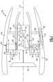
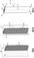
Figure 2 is a schematic view of an example strut heat exchanger embodiment. -
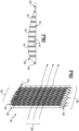
Figure 3 is a partial cross-sectional view of the example strut heat exchanger embodiment ofFigure 2 . -
Figure 4 a partial sectional view of the example strut heat exchanger embodiment ofFigure 2 . -
Figure 5 is another partial sectional view of the example strut heat exchanger embodiment ofFigure 2 . -
Figure 6 is another partial sectional view of the example strut heat exchanger embodiment ofFigure 2 . -
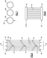
Figure 7 is a schematic view of a portion of an example tube assembly of a disclosed strut heat exchanger embodiment. -
Figure 8 is a schematic view of an example tube assembly embodiment. -
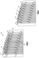
Figure 9 is a schematic view of a portion of an example fairing assembly of an example strut heat exchanger embodiment at an initial assembly step. -
Figure 10 is another schematic view of the example fairing assembly ofFigure 9 at an intermediate assembly step. -
Figure 11 is a schematic view of the example fairing assembly ofFigure 9 at a final assembly step. -
Figure 1 schematically illustrates anexample propulsion system 20 that includes astrut heat exchanger 56 disposed between an inner nacelle 44 and an outer nacelle. Thestrut heat exchanger 56 includes an inner cavity within which thermal energy is transferred between different flows. - The
example propulsion system 20 includes afan section 24 and acore engine section 22. Thecore engine section 22 includes acompressor section 26, acombustor section 28 and theturbine section 30 disposed along an engine longitudinal axis A. Thefan section 24 drives inlet airflow asbypass airflow 58 along a bypass flow path B, while thecompressor section 26 draws air in along a core flow path C. The inlet airflow is compressed and communicated to thecombustor section 28 where the compressed core airflow is mixed with afuel flow 34 from afuel system 32 and ignited to generate theexhaust gas flow 36. Theexhaust gas flow 36 expands through theturbine section 30 where energy is extracted to generate a mechanical power output utilized to drive thefan section 24 and thecompressor section 26. - The example
core engine section 22 is a reverse flow engine where core flow is drawn through thecompressor section 28 and communicated forward through thecombustor section 28 and theturbine section 30. Theexhaust gas flow 36 from theturbine section 30 is communicated through acondenser 42 to generate awater flow 38. Thewater flow 38 is heated within anevaporator 40 to generate asteam flow 54 that maybe injected into the core flow path C to increase power output. - The
core engine section 22 is disposed within the inner nacelle 44 and thefan 24 is disposed within anouter nacelle 46. Theouter nacelle 46 circumscribes the inner nacelle 44 and the bypass flow path B is disposed within a radial space defined between the inner nacelle 44 and theouter nacelle 46.Structural supports 86 extend through the bypass flow path B and support thecore engine section 22. - The example propulsion system includes the
strut heat exchangers 56 that are utilized to extract and generate asteam flow 54. In the disclosed example, thestrut heat exchanger 56 is part of anevaporator 40 and communicates thermal energy from at least a portion of theexhaust gas flow 36 into awater flow 38 to generate thesteam flow 54. The transfer of thermal energy between theexhaust gas flow 36 and thewater flow 38 occurs within thestrut heat exchanger 56. The bypass flow is not utilized to provide thermal transfer within thestrut heat exchanger 56. In a disclosed example, a portion of theexhaust gas flow 36 is communicated radially outward through thestrut heat exchanger 56. Thewater flow 38 is communicated radially inward, counter to theexhaust gas flow 36. Accordingly, the examplestrut heat exchanger 56 is a counter flow heat exchanger. - The example
exhaust gas flow 36 and thewater flow 38 are schematically shown. Theflows strut heat exchanger 56 by ducting and conduits disposed within thecore engine section 22, the inner nacelle 44 and theouter nacelle 46. In one example embodiment, thestrut heat exchanger 56 includes aninner opening 48 that opens through the inner nacelle 44 and anouter opening 50 that opens into aspace 52 within theouter nacelle 46. Anexample condenser 42 is disposed within thespace 52 of theouter nacelle 46. Although an example configuration and orientation of theevaporator 40 andcondenser 42 are shown by way of the disclosed example, other configurations and orientations of theevaporator 40 andcondenser 42 may be utilized and are within the scope and contemplation of this disclosure. - Moreover, although an example engine architecture is disclosed, other turbine engine architectures are within the contemplation and scope of this disclosure. Although the disclosed non-limiting embodiment depicts a turbofan turbine engine, it should be understood that the concepts described herein are not limited to use with turbofans as the teachings may be applied to other types of turbine engines. Additionally, the features of this disclosure may be applied to other engine configurations utilized to generate shaft power.
- The steam flow 54 from the
evaporator 40 is injected into the core flow path C at or upstream of thecombustor 28 and increases mass flow through theturbine section 30 and thereby increases engine power and efficiency. Thepropulsion system 20 has an increased power output from the injectedsteam 54 due to an increasing mass flow through theturbine section 30 without a corresponding increase in work from thecompressor section 26. Although thesteam flow 54 is shown as being injected into thecombustor 28, thesteam flow 54 may be injected at other locations along the core flow path C and remain within the contemplation and scope of this disclosure. - Referring to
Figures 2 and 3 , with continued reference toFigure 1 , the disclosed examplestrut heat exchanger 56 includes a fairingassembly 68 that extends between aleading edge 60, trailingedge 62,first end 64 and asecond end 66. In this example embodiment, thefirst end 64 is disposed on a radially inner side and includes theopening 48 through the inner nacelle 44. Thesecond end 66 is disposed on a radially outer side and opens into thespace 52 of theouter nacelle 46. Aninner cavity 74 is defined by the fairingassembly 68 and provides a passage for theexhaust gas flow 36. A plurality oftube assemblies 76 extend through theinner cavity 74 between thefirst end 64 and thesecond end 66. Thetube assemblies 76 contain thewater flow 38. Accordingly, theexhaust gas flow 36 through theinner cavity 74 is in thermal communication with thewater flow 38 within thetube assemblies 76. - Referring to
Figures 4 and 5 with continued reference toFigures 2 and 3 , thetube assemblies 76 are bundled together and held in place by supports 78. The example supports 78 provide structure and rigidity to support and hold thetube assemblies 76 in place. However, thesupports 78 are not intended to provide structural support for thecore engine section 22 or thenacelles 44, 46. In the disclosed example, each of the plurality oftube assemblies 76 include a plurality of supports 78. The supports 78 are spaced apart radially between thefirst end 64 and thesecond end 66 of thestrut heat exchanger 56. - Referring to
Figure 6 , with continued reference toFigures 4 and 5 , the example supports 78 provide the additional function of disrupting laminar flow of theexhaust gas flow 36 to improve thermal transfer. In the disclosed example shown inFigure 6 , thesupports 78 include a general chevron shapedturbulator 75 that points counter to the direction of theexhaust gas flow 36. The point of the chevron shapedturbulator 75 points toward theinner opening 48 and the incomingexhaust gas flow 36. The configurations of thesupports 78 disrupt theexhaust gas flow 36 along the surface of thetube assemblies 76 and spread the flow and thermal energy outward evenly across thetube assemblies 76. Although a support and turbulator configuration is shown by way of example, other support and flow disrupting turbulator features and configurations may be utilized and are within the contemplation of this disclosure - Referring to
Figure 7 ,tubes 88 of thetube assembly 76 are shown in cross-section. Theexample tubes 88 are provided as micro-tubes with anouter diameter 80 that is less than or equal to about ¼ inch (6.35 mm). In another example embodiment, theouter diameter 80 is between about 1/8 inch (3.175 mm) and 1.50 inches (38.10 mm). - The
tubes 88 are constructed of material compatible with the temperatures encountered during operation and that provides for the communication of thermal energy between flows. Moreover, although theexample tubes 88 are disclosed as micro-tubes, other tube configurations and shapes could be utilized and are within the contemplation of this disclosure. For example, thetubes 88 may be oval, square, or irregularly shaped to conform to space available space. Moreover, larger tubes may be utilized that provide for thermal transfer between flows. - Referring to
Figure 8 , anexample tube assembly 76 is schematically shown and includes afirst manifold 82 and asecond manifold 84. Themanifolds tube assemblies 76. In this example, thewater flow 38 is communicated into theexample tube assembly 76 through thesecond manifold 84. Thewater flow 38 accepts heat from theexhaust gas flow 36 within thetube assembly 76 and is transformed into thesteam flow 54 that is communicated to the core flow path C. The manifolds 82, 84 are shown schematically and may comprise one or several structures for communicating water and steam flow through thestrut heat exchanger 56. - Referring to
Figures 9, 10 and 11 , theexample fairing assembly 68 includes afirst fairing 70 and asecond fairing 72 that wrap around thetube assemblies 76. The example first andsecond fairing assemblies leading edge 60 and the trailingedge 62. The example fairings 70, 72 are formed from sheet material and provided the limited amount of structural rigidity required. Because the examplestrut heat exchanger 56 is not an engine load bearing structure, thefairings fairings fairings fairings exhaust gas flow 36, the material utilized for thefairings exhaust gas flow 36. - Accordingly, the example
strut heat exchanger 56 provides a radial space between nacelles for the transfer of thermal energy between an exhaust gas flow and a water flow. - Although an example embodiment has been disclosed, a worker of ordinary skill in this art would recognize that certain modifications would come within the scope of this disclosure. For that reason, the following claims should be studied to determine the scope and content of this disclosure.
Claims (15)
- An aircraft propulsion system comprising:a core engine section (22) defining a core flow path (C) where an inlet airflow is compressed, mixed with fuel, and ignited to generate an exhaust gas flow;an inner nacelle assembly (44) surrounding the core engine section (22);an outer nacelle assembly (46) spaced radially apart from the inner nacelle assembly (44); anda strut heat exchanger (56) extending radially between the inner nacelle assembly (44) and the outer nacelle assembly (46), wherein within the strut heat exchanger (56) a portion of the exhaust gas flow (36) is placed in thermal communication with a second flow for transferring thermal energy.
- The aircraft propulsion system as recited in claim 1, wherein the strut heat exchanger (56) comprises an outer fairing assembly (68) defining an outer surface that extends between a leading edge (60), a trailing edge (62), a radially inner end at the inner nacelle assembly (44) and a radially outer end at the outer nacelle assembly (46), optionally wherein the outer fairing assembly (68) includes a first fairing (70) and a second fairing (72) that are attachable to each other.
- The aircraft propulsion system as recited in claim 1 or 2, wherein the strut heat exchanger (56) includes an inner cavity (74) that extends between an inner opening (48) open through the inner nacelle assembly (44) and an outer opening (50) that is open into the outer nacelle assembly (46), and a plurality of tube assemblies (76) that extend through the inner cavity (74) between the inner nacelle assembly (44) and the outer nacelle assembly (46).
- The aircraft propulsion system as recited in claim 3, wherein the portion of the exhaust gas flow (36) is communicated through the inner cavity (74) and the second flow is communicated through at least one of the plurality of tube assemblies (76).
- The aircraft propulsion system as recited in claim 3 or 4, wherein the plurality of tube assemblies (76) comprise a plurality of micro-tubes (88) supported by at least one support member (78).
- The aircraft propulsion system as recited in claim 5, wherein the support member (78) includes a turbulator (75) for disrupting laminar flow adjacent to the plurality of tube assemblies (76).
- The aircraft propulsion system as recited in any of claims 3 to 6, wherein the portion of the exhaust gas flow (36) flows through the inner cavity (74) in a first radial direction and the second flow flows through the at least one of the plurality of tube assemblies (76) in a second radial direction counter to the first radial direction.
- The aircraft propulsion system as recited in any preceding claim, further including a condenser (42) where water is extracted from the exhaust gas flow (36) and an evaporator system (40) where thermal energy from the exhaust gas flow (36) is utilized to generate a steam flow from at least a portion of water extracted by the condenser (42) for injection into the core flow path (C), wherein the second flow comprises a flow of water and at least a portion of thermal energy from the exhaust gas flow (36) is communicated to the water flow within the strut heat exchanger (56), optionally wherein a portion of the condenser (42) is disposed within the outer nacelle (46).
- A heat exchanger for an aircraft propulsion system comprising:an outer fairing assembly (68) defining an outer surface that extends between a leading edge (60), a trailing edge (62), a radially inner end, and a radially outer end;an inner cavity (74) defined within the outer fairing that defines a first flow path that extends between an inner opening (48) disposed at the radially inner end and an outer opening (50) disposed at the radially outer end; anda plurality of tube assemblies (76) that extend through the inner cavity (74) that define a second flow path between the inner end and the outer end, wherein the first flow path and the second flow path are configured to transfer thermal energy between flows within the first flow path and the second flow path.
- The heat exchanger as recited in claim 9, wherein:the plurality of tube assemblies (76) comprise a plurality of micro-tubes (88) supported by at least one support member (78), optionally wherein the support member (78) includes a turbulator (75) for disrupting laminar flow adjacent to the plurality of tube assemblies (76); and/orthe inner cavity (74) is configured to receive a portion of an exhaust gas flow (36) generated by the aircraft propulsion system.
- The heat exchanger as recited in claim 9 or 10, wherein:each of the plurality of tube assemblies (76) are configured to receive a portion of a flow that accepts thermal energy from the exhaust gas flow; and/orthe outer fairing assembly (68) includes a first fairing (70) and a second fairing (72) that are attachable to each other.
- A method of operating a gas turbine engine, the method comprising:generating an exhaust gas flow;routing a portion of the exhaust gas flow (36) through an inner cavity (74) of a strut heat exchanger (56);extracting water from the exhaust gas flow (36) in a condenser (42);routing a flow of extracted water through a plurality of tubes (88) extending through the strut heat exchanger (56) in thermal communication with the exhaust gas flow; andgenerating a steam flow by heating the portion of the flow of extracted water with heat from the exhaust gas flow (36) within the strut heat exchanger (56).
- The method as recited in claim 12, wherein a portion of the condenser (42) is disposed within an outer nacelle (46) and the method includes routing a portion of the exhaust gas flow (36) through the condenser (42) within the outer nacelle (46).
- The method as recited in claim 12 or 13, further comprising directing the portion of exhaust gas flow (36) through the inner cavity (74) in a first radial direction and directing the flow of extracted water through the plurality of tubes (88) in a second radial direction that is counter to the first radial direction.
- The method as recited in any of claims 12 to 14, further comprising disrupting laminar flow of the exhaust gas flow (36) with turbulators (75) disposed on structures (78) that support the plurality of tubes (88).
Applications Claiming Priority (1)
| Application Number | Priority Date | Filing Date | Title |
|---|---|---|---|
| US18/503,279 US12331684B2 (en) | 2023-11-07 | 2023-11-07 | Strut microtube counterflow evaporator |
Publications (2)
| Publication Number | Publication Date |
|---|---|
| EP4553300A2 true EP4553300A2 (en) | 2025-05-14 |
| EP4553300A3 EP4553300A3 (en) | 2025-07-02 |
Family
ID=92711261
Family Applications (1)
| Application Number | Title | Priority Date | Filing Date |
|---|---|---|---|
| EP24199055.5A Pending EP4553300A3 (en) | 2023-11-07 | 2024-09-06 | Strut microtube counterflow evaporator |
Country Status (2)
| Country | Link |
|---|---|
| US (1) | US12331684B2 (en) |
| EP (1) | EP4553300A3 (en) |
Family Cites Families (26)
| Publication number | Priority date | Publication date | Assignee | Title |
|---|---|---|---|---|
| US2961150A (en) * | 1958-12-30 | 1960-11-22 | Gen Electric | Frame structure for turbo-machine |
| US3266564A (en) * | 1964-02-11 | 1966-08-16 | Curtiss Wright Corp | Liquid metal rotary heat exchanger |
| US3320749A (en) * | 1965-10-04 | 1967-05-23 | Gen Motors Corp | Regenerative fan engine |
| GB2041090A (en) * | 1979-01-31 | 1980-09-03 | Rolls Royce | By-pass gas turbine engines |
| US6712131B1 (en) * | 1998-03-12 | 2004-03-30 | Nederlandse Organisatie Voor Toegepast - Natuurwetenschappelijk Onderzoek Tno | Method for producing an exchanger and exchanger |
| US6406254B1 (en) * | 1999-05-10 | 2002-06-18 | General Electric Company | Cooling circuit for steam and air-cooled turbine nozzle stage |
| GB0719786D0 (en) * | 2007-10-11 | 2007-11-21 | Rolls Royce Plc | A vane and a vane assembly for a gas turbine engine |
| US7775031B2 (en) * | 2008-05-07 | 2010-08-17 | Wood Ryan S | Recuperator for aircraft turbine engines |
| US7861510B1 (en) * | 2008-11-22 | 2011-01-04 | Florida Turbine Technologies, Inc. | Ceramic regenerator for a gas turbine engine |
| KR101125004B1 (en) * | 2009-12-04 | 2012-03-27 | 기아자동차주식회사 | Exhaust heat recovery apparatus |
| US8616834B2 (en) | 2010-04-30 | 2013-12-31 | General Electric Company | Gas turbine engine airfoil integrated heat exchanger |
| EP2918957A1 (en) * | 2014-03-13 | 2015-09-16 | BAE Systems PLC | Heat exchanger |
| EP3117169B1 (en) * | 2014-03-13 | 2018-05-09 | BAE Systems PLC | Heat exchanger |
| US20150354382A1 (en) * | 2014-06-06 | 2015-12-10 | General Electric Company | Exhaust frame cooling via strut cooling passages |
| US20180149085A1 (en) * | 2016-11-28 | 2018-05-31 | General Electric Company | Exhaust frame cooling via cooling flow reversal |
| US10830056B2 (en) | 2017-02-03 | 2020-11-10 | General Electric Company | Fluid cooling systems for a gas turbine engine |
| US11078795B2 (en) | 2017-11-16 | 2021-08-03 | General Electric Company | OGV electroformed heat exchangers |
| DE102018208026A1 (en) * | 2018-05-22 | 2019-11-28 | MTU Aero Engines AG | An exhaust treatment device, aircraft propulsion system, and method of treating an exhaust flow |
| DE102019203595A1 (en) * | 2019-03-15 | 2020-09-17 | MTU Aero Engines AG | Aircraft |
| US11650018B2 (en) * | 2020-02-07 | 2023-05-16 | Raytheon Technologies Corporation | Duct mounted heat exchanger |
| US12071889B2 (en) * | 2022-04-05 | 2024-08-27 | General Electric Company | Counter-rotating turbine |
| US12129774B2 (en) * | 2022-05-19 | 2024-10-29 | Rtx Corporation | Hydrogen fueled turbine engine pinch point water separator |
| WO2023237152A1 (en) * | 2022-06-06 | 2023-12-14 | MTU Aero Engines AG | Propulsion system for an aircraft |
| US12092022B2 (en) * | 2023-02-06 | 2024-09-17 | Rtx Corporation | Forward mounted hydrogen steam injected and inter-cooled turbine engine with octopus ducting |
| US12012892B1 (en) * | 2023-05-19 | 2024-06-18 | Rtx Corporation | Water separator for turbine engine |
| US12173669B1 (en) * | 2023-08-18 | 2024-12-24 | General Electric Company | Turbine engine with fan bypass water injection to augment thrust |
-
2023
- 2023-11-07 US US18/503,279 patent/US12331684B2/en active Active
-
2024
- 2024-09-06 EP EP24199055.5A patent/EP4553300A3/en active Pending
Also Published As
| Publication number | Publication date |
|---|---|
| US12331684B2 (en) | 2025-06-17 |
| EP4553300A3 (en) | 2025-07-02 |
| US20250146440A1 (en) | 2025-05-08 |
Similar Documents
| Publication | Publication Date | Title |
|---|---|---|
| EP4279722B1 (en) | WATER SEPARATOR FOR HYDROGEN-DRIVED TURBINE ENGINE | |
| US11143106B2 (en) | Combustion section heat transfer system for a propulsion system | |
| US12163467B2 (en) | Condenser for hydrogen steam injected turbine engine | |
| EP4279718B1 (en) | Hydrogen fueled turbine engine condenser duct | |
| EP2236750B1 (en) | An impingement cooling arrangement for a gas turbine engine | |
| EP4279723A1 (en) | Hydrogen steam injected and inter-cooled turbine engine | |
| EP4656858A2 (en) | Circumferential flow condenser arrangement for an aircraft propulsion system | |
| EP4455465B1 (en) | Offset core with side ejector nacelle nozzles | |
| US11371786B2 (en) | Heat exchanger for a gas turbine engine | |
| EP4089273B1 (en) | Heat exchanger tube support | |
| EP4279721B1 (en) | Reverse flow hydrogen steam injected turbine engine | |
| EP4726197A1 (en) | Thrust reverser in condenser exit duct | |
| EP4089356B1 (en) | Heat exchanger tube support | |
| EP4553300A2 (en) | Strut microtube counterflow evaporator | |
| EP4502342A1 (en) | Steam heated flange for thermal gradient control | |
| EP4656860A1 (en) | Axial flow tapered condenser arrangement for an aircraft propulsion system | |
| EP4656857A2 (en) | Axial flow angled condenser arrangement for an aircraft propulsion system | |
| US12510023B1 (en) | Fan case mounted evaporator for aircraft turbine engine | |
| EP4474629A1 (en) | Water cooled exhaust duct |
Legal Events
| Date | Code | Title | Description |
|---|---|---|---|
| PUAI | Public reference made under article 153(3) epc to a published international application that has entered the european phase |
Free format text: ORIGINAL CODE: 0009012 |
|
| STAA | Information on the status of an ep patent application or granted ep patent |
Free format text: STATUS: THE APPLICATION HAS BEEN PUBLISHED |
|
| AK | Designated contracting states |
Kind code of ref document: A2 Designated state(s): AL AT BE BG CH CY CZ DE DK EE ES FI FR GB GR HR HU IE IS IT LI LT LU LV MC ME MK MT NL NO PL PT RO RS SE SI SK SM TR |
|
| PUAL | Search report despatched |
Free format text: ORIGINAL CODE: 0009013 |
|
| AK | Designated contracting states |
Kind code of ref document: A3 Designated state(s): AL AT BE BG CH CY CZ DE DK EE ES FI FR GB GR HR HU IE IS IT LI LT LU LV MC ME MK MT NL NO PL PT RO RS SE SI SK SM TR |
|
| RIC1 | Information provided on ipc code assigned before grant |
Ipc: F28D 7/16 20060101ALI20250527BHEP Ipc: F02C 7/14 20060101ALI20250527BHEP Ipc: F02C 3/34 20060101ALI20250527BHEP Ipc: F02C 3/30 20060101ALI20250527BHEP Ipc: F02C 3/22 20060101AFI20250527BHEP |
|
| STAA | Information on the status of an ep patent application or granted ep patent |
Free format text: STATUS: REQUEST FOR EXAMINATION WAS MADE |
|
| 17P | Request for examination filed |
Effective date: 20251231 |