EP4553291A1 - Verstellbares schaufelblatt - Google Patents
Verstellbares schaufelblatt Download PDFInfo
- Publication number
- EP4553291A1 EP4553291A1 EP24207474.8A EP24207474A EP4553291A1 EP 4553291 A1 EP4553291 A1 EP 4553291A1 EP 24207474 A EP24207474 A EP 24207474A EP 4553291 A1 EP4553291 A1 EP 4553291A1
- Authority
- EP
- European Patent Office
- Prior art keywords
- interface
- airfoil
- yielding
- airfoil assembly
- crushable
- Prior art date
- Legal status (The legal status is an assumption and is not a legal conclusion. Google has not performed a legal analysis and makes no representation as to the accuracy of the status listed.)
- Pending
Links
Images




Classifications
-
- F—MECHANICAL ENGINEERING; LIGHTING; HEATING; WEAPONS; BLASTING
- F01—MACHINES OR ENGINES IN GENERAL; ENGINE PLANTS IN GENERAL; STEAM ENGINES
- F01D—NON-POSITIVE DISPLACEMENT MACHINES OR ENGINES, e.g. STEAM TURBINES
- F01D17/00—Regulating or controlling by varying flow
- F01D17/10—Final actuators
- F01D17/12—Final actuators arranged in stator parts
- F01D17/14—Final actuators arranged in stator parts varying effective cross-sectional area of nozzles or guide conduits
- F01D17/16—Final actuators arranged in stator parts varying effective cross-sectional area of nozzles or guide conduits by means of nozzle vanes
- F01D17/162—Final actuators arranged in stator parts varying effective cross-sectional area of nozzles or guide conduits by means of nozzle vanes for axial flow, i.e. the vanes turning around axes which are essentially perpendicular to the rotor centre line
-
- F—MECHANICAL ENGINEERING; LIGHTING; HEATING; WEAPONS; BLASTING
- F01—MACHINES OR ENGINES IN GENERAL; ENGINE PLANTS IN GENERAL; STEAM ENGINES
- F01D—NON-POSITIVE DISPLACEMENT MACHINES OR ENGINES, e.g. STEAM TURBINES
- F01D21/00—Shutting-down of machines or engines, e.g. in emergency; Regulating, controlling, or safety means not otherwise provided for
- F01D21/04—Shutting-down of machines or engines, e.g. in emergency; Regulating, controlling, or safety means not otherwise provided for responsive to undesired position of rotor relative to stator or to breaking-off of a part of the rotor, e.g. indicating such position
- F01D21/045—Shutting-down of machines or engines, e.g. in emergency; Regulating, controlling, or safety means not otherwise provided for responsive to undesired position of rotor relative to stator or to breaking-off of a part of the rotor, e.g. indicating such position special arrangements in stators or in rotors dealing with breaking-off of part of rotor
-
- F—MECHANICAL ENGINEERING; LIGHTING; HEATING; WEAPONS; BLASTING
- F01—MACHINES OR ENGINES IN GENERAL; ENGINE PLANTS IN GENERAL; STEAM ENGINES
- F01D—NON-POSITIVE DISPLACEMENT MACHINES OR ENGINES, e.g. STEAM TURBINES
- F01D5/00—Blades; Blade-carrying members; Heating, heat-insulating, cooling or antivibration means on the blades or the members
- F01D5/12—Blades
- F01D5/28—Selecting particular materials; Particular measures relating thereto; Measures against erosion or corrosion
- F01D5/282—Selecting composite materials, e.g. blades with reinforcing filaments
-
- F—MECHANICAL ENGINEERING; LIGHTING; HEATING; WEAPONS; BLASTING
- F01—MACHINES OR ENGINES IN GENERAL; ENGINE PLANTS IN GENERAL; STEAM ENGINES
- F01D—NON-POSITIVE DISPLACEMENT MACHINES OR ENGINES, e.g. STEAM TURBINES
- F01D5/00—Blades; Blade-carrying members; Heating, heat-insulating, cooling or antivibration means on the blades or the members
- F01D5/30—Fixing blades to rotors; Blade roots ; Blade spacers
-
- F—MECHANICAL ENGINEERING; LIGHTING; HEATING; WEAPONS; BLASTING
- F01—MACHINES OR ENGINES IN GENERAL; ENGINE PLANTS IN GENERAL; STEAM ENGINES
- F01D—NON-POSITIVE DISPLACEMENT MACHINES OR ENGINES, e.g. STEAM TURBINES
- F01D7/00—Rotors with blades adjustable in operation; Control thereof
-
- F—MECHANICAL ENGINEERING; LIGHTING; HEATING; WEAPONS; BLASTING
- F01—MACHINES OR ENGINES IN GENERAL; ENGINE PLANTS IN GENERAL; STEAM ENGINES
- F01D—NON-POSITIVE DISPLACEMENT MACHINES OR ENGINES, e.g. STEAM TURBINES
- F01D9/00—Stators
- F01D9/02—Nozzles; Nozzle boxes; Stator blades; Guide conduits, e.g. individual nozzles
- F01D9/04—Nozzles; Nozzle boxes; Stator blades; Guide conduits, e.g. individual nozzles forming ring or sector
-
- F—MECHANICAL ENGINEERING; LIGHTING; HEATING; WEAPONS; BLASTING
- F05—INDEXING SCHEMES RELATING TO ENGINES OR PUMPS IN VARIOUS SUBCLASSES OF CLASSES F01-F04
- F05D—INDEXING SCHEME FOR ASPECTS RELATING TO NON-POSITIVE-DISPLACEMENT MACHINES OR ENGINES, GAS-TURBINES OR JET-PROPULSION PLANTS
- F05D2250/00—Geometry
- F05D2250/20—Three-dimensional
- F05D2250/28—Three-dimensional patterned
- F05D2250/283—Three-dimensional patterned honeycomb
-
- F—MECHANICAL ENGINEERING; LIGHTING; HEATING; WEAPONS; BLASTING
- F05—INDEXING SCHEMES RELATING TO ENGINES OR PUMPS IN VARIOUS SUBCLASSES OF CLASSES F01-F04
- F05D—INDEXING SCHEME FOR ASPECTS RELATING TO NON-POSITIVE-DISPLACEMENT MACHINES OR ENGINES, GAS-TURBINES OR JET-PROPULSION PLANTS
- F05D2250/00—Geometry
- F05D2250/90—Variable geometry
-
- F—MECHANICAL ENGINEERING; LIGHTING; HEATING; WEAPONS; BLASTING
- F05—INDEXING SCHEMES RELATING TO ENGINES OR PUMPS IN VARIOUS SUBCLASSES OF CLASSES F01-F04
- F05D—INDEXING SCHEME FOR ASPECTS RELATING TO NON-POSITIVE-DISPLACEMENT MACHINES OR ENGINES, GAS-TURBINES OR JET-PROPULSION PLANTS
- F05D2260/00—Function
- F05D2260/30—Retaining components in desired mutual position
- F05D2260/38—Retaining components in desired mutual position by a spring, i.e. spring loaded or biased towards a certain position
-
- F—MECHANICAL ENGINEERING; LIGHTING; HEATING; WEAPONS; BLASTING
- F05—INDEXING SCHEMES RELATING TO ENGINES OR PUMPS IN VARIOUS SUBCLASSES OF CLASSES F01-F04
- F05D—INDEXING SCHEME FOR ASPECTS RELATING TO NON-POSITIVE-DISPLACEMENT MACHINES OR ENGINES, GAS-TURBINES OR JET-PROPULSION PLANTS
- F05D2260/00—Function
- F05D2260/70—Adjusting of angle of incidence or attack of rotating blades
-
- F—MECHANICAL ENGINEERING; LIGHTING; HEATING; WEAPONS; BLASTING
- F05—INDEXING SCHEMES RELATING TO ENGINES OR PUMPS IN VARIOUS SUBCLASSES OF CLASSES F01-F04
- F05D—INDEXING SCHEME FOR ASPECTS RELATING TO NON-POSITIVE-DISPLACEMENT MACHINES OR ENGINES, GAS-TURBINES OR JET-PROPULSION PLANTS
- F05D2260/00—Function
- F05D2260/70—Adjusting of angle of incidence or attack of rotating blades
- F05D2260/74—Adjusting of angle of incidence or attack of rotating blades by turning around an axis perpendicular the rotor centre line
-
- F—MECHANICAL ENGINEERING; LIGHTING; HEATING; WEAPONS; BLASTING
- F05—INDEXING SCHEMES RELATING TO ENGINES OR PUMPS IN VARIOUS SUBCLASSES OF CLASSES F01-F04
- F05D—INDEXING SCHEME FOR ASPECTS RELATING TO NON-POSITIVE-DISPLACEMENT MACHINES OR ENGINES, GAS-TURBINES OR JET-PROPULSION PLANTS
- F05D2270/00—Control
- F05D2270/01—Purpose of the control system
- F05D2270/09—Purpose of the control system to cope with emergencies
-
- F—MECHANICAL ENGINEERING; LIGHTING; HEATING; WEAPONS; BLASTING
- F05—INDEXING SCHEMES RELATING TO ENGINES OR PUMPS IN VARIOUS SUBCLASSES OF CLASSES F01-F04
- F05D—INDEXING SCHEME FOR ASPECTS RELATING TO NON-POSITIVE-DISPLACEMENT MACHINES OR ENGINES, GAS-TURBINES OR JET-PROPULSION PLANTS
- F05D2300/00—Materials; Properties thereof
- F05D2300/50—Intrinsic material properties or characteristics
- F05D2300/501—Elasticity
-
- F—MECHANICAL ENGINEERING; LIGHTING; HEATING; WEAPONS; BLASTING
- F05—INDEXING SCHEMES RELATING TO ENGINES OR PUMPS IN VARIOUS SUBCLASSES OF CLASSES F01-F04
- F05D—INDEXING SCHEME FOR ASPECTS RELATING TO NON-POSITIVE-DISPLACEMENT MACHINES OR ENGINES, GAS-TURBINES OR JET-PROPULSION PLANTS
- F05D2300/00—Materials; Properties thereof
- F05D2300/60—Properties or characteristics given to material by treatment or manufacturing
- F05D2300/612—Foam
-
- Y—GENERAL TAGGING OF NEW TECHNOLOGICAL DEVELOPMENTS; GENERAL TAGGING OF CROSS-SECTIONAL TECHNOLOGIES SPANNING OVER SEVERAL SECTIONS OF THE IPC; TECHNICAL SUBJECTS COVERED BY FORMER USPC CROSS-REFERENCE ART COLLECTIONS [XRACs] AND DIGESTS
- Y02—TECHNOLOGIES OR APPLICATIONS FOR MITIGATION OR ADAPTATION AGAINST CLIMATE CHANGE
- Y02T—CLIMATE CHANGE MITIGATION TECHNOLOGIES RELATED TO TRANSPORTATION
- Y02T50/00—Aeronautics or air transport
- Y02T50/60—Efficient propulsion technologies, e.g. for aircraft
Definitions
- the disclosure generally relates to an airfoil assembly, and more specifically to an airfoil assembly with a variable pitch airfoil.
- Turbine engines and particularly gas or combustion turbine engines, are rotary engines that extract energy from a flow of gases passing through a fan with a plurality of fan blades, then into the engine through a series of compressor stages, which include pairs of rotating blades and stationary vanes, through a combustor, and then through a series of turbine stages, which include pairs of rotating blade and stationary vanes.
- the blades are mounted to rotating disks, while the vanes are mounted to stator disks.
- air is brought into the compressor section through the fan section where it is then pressurized in the compressor and mixed with fuel in the combustor for generating hot combustion gases which flow downstream through the turbine stages where the air is expanded and exhausted out an exhaust section.
- the expansion of the air in the turbine section is used to drive the rotating sections of the fan section and the compressor section.
- the drawing in of air, the pressurization of the air, and the expansion of the air is done, in part, through rotation of various rotating blades mounted to respective disks throughout the fan section, the compressor section and the turbine section, respectively.
- aspects of the disclosure herein are directed to a turbine engine including an airfoil assembly with a mounting structure and a yielding interface.
- the airfoil assembly can be used at one or more locations within the turbine engine.
- the airfoil assembly is suitable as a fan blade in a fan section of a turbine engine.
- Other locations, such as the compressor section and turbine section are contemplated.
- the airfoil assembly can be mounted in a variety of ways. One such mounting is securing the blades to a spinner of the fan section, directly, or via a pitch control assembly.
- the yielding interface of the airfoil assembly is formed to enable yielding in a plurality of directions.
- the term yielding is used in this application to describe deflection which may or may not result in plastic deformation. In some applications, the yielding interface deflects to reduce load but does not plastically deform.
- the yielding interface described herein has been developed from tests and simulation analyses covering the ingestion of birds of varying sizes at varying span positions. The yielding interface described herein helps to mitigate incipient damage due to bird strike as well as ice impact, foreign object debris (FOD) strike, and even fan blade out debris strike.
- FOD foreign object debris
- This yielding can be enabled by forming the yielding interface from a honeycomb structure, a spring, or material having variable stiffness.
- Several embodiments for enabling yielding such that the airfoil assembly can withstand high mechanical stresses associated with the operation of the turbine engine while providing lightweight construction are discussed herein.
- the present disclosure will be described with respect to an airfoil assembly for a turbine engine, specifically an airfoil assembly provided within a fan section of the turbine engine. It will be understood, however, that aspects of the disclosure described herein are not so limited and can have general applicability within other engines or within other portions of the turbine engine.
- the disclosure can have applicability for an airfoil assembly in other engines or vehicles, and can be used to provide benefits in industrial, commercial, and residential applications.
- aspects of this disclosure will be directed towards a composite blade assembly including a mounting structure. It will be appreciated that aspects of this disclosure are directed towards any airfoil assembly. Further the airfoil assembly is not limited and could be a composite blade assembly or a composite vane assembly.
- upstream refers to a direction that is opposite the fluid flow direction
- downstream refers to a direction that is in the same direction as the fluid flow.
- forward means in front of something and "aft” or “rearward” means behind something.
- fore / forward can mean upstream and aft / rearward can mean downstream.
- radial refers to a direction away from a common center.
- radial refers to a direction along a ray extending between a center longitudinal axis of the engine and an outer engine circumference.
- set or a “set of elements” can be any number of elements, including only one.
- the term "fluid” or iterations thereof can refer to any suitable fluid within the gas turbine engine wherein at least a portion of the gas turbine engine is exposed to such as, but not limited to, combustion gases, ambient air, pressurized airflow, working airflow, or any combination thereof. It is yet further contemplated that the gas turbine engine can be other suitable turbine engines such as, but not limited to, a steam turbine engine or a supercritical carbon dioxide turbine engine. As a non-limiting example, the term “fluid” can refer to steam in a steam turbine engine, or to carbon dioxide in a supercritical carbon dioxide turbine engine.
- a composite is indicative of a component having two or more materials.
- a composite can be a combination of at least two or more metallic, non-metallic, or a combination of metallic and non-metallic elements or materials.
- Examples of a composite material can be, but not limited to, a polymer matrix composite (PMC), a ceramic matrix composite (CMC), metal matrix composite (MMC), carbon fiber, polymeric resin, thermoplastic, bismaleimide (BMI), polyimide materials, epoxy resin, glass fiber, and silicon matrix materials.
- FIG. 1 is a schematic cross-sectional diagram of a turbine engine 10 for an aircraft.
- the turbine engine 10 is illustrated as an open rotor turbine engine.
- the turbine engine 10 has a generally longitudinally extending axis or engine centerline 12 extending from a forward end 14 to an aft end 16.
- the turbine engine 10 includes, in downstream serial flow relationship, a set of circumferentially spaced blades or propellers defining a fan section 18 including a fan 20, a compressor section 22 including a booster or low pressure (LP) compressor 24 and a high pressure (HP) compressor 26, a combustion section 28 including a combustor 30, a turbine section 32 including an HP turbine 34, and an LP turbine 36, and an exhaust section 38.
- the turbine engine 10 as described herein is meant as a non-limiting example, and other architectures are possible, such as, but not limited to, a steam turbine engine, a supercritical carbon dioxide turbine engine, or any other suitable turbine engine.
- An exterior surface, defined by a nacelle 40, of the turbine engine 10 extends from the forward end 14 of the turbine engine 10 toward the aft end 16 of the turbine engine 10 and covers at least a portion of the compressor section 22, the combustion section 28, the turbine section 32, and the exhaust section 38.
- the fan section 18 can be positioned at a forward portion of the nacelle 40 and extend radially outward from the nacelle 40 of the turbine engine 10, specifically, the fan section 18 extends radially outward from the nacelle 40.
- the fan section 18 includes a set of fan blades 42.
- the set of fan blades 42 are mounted to a spinner 43 rotatable about the engine centerline 12.
- a set of outlet guide vanes (OGV) 82 is located downstream from the set of fan blades 42, both disposed radially about the engine centerline 12.
- the turbine engine 10 includes any number of one or more sets of rotating blades or propellers (e.g., the set of fan blades 42) disposed upstream of a set of stationary fan vanes (e.g., the set of OGVs 82).
- the turbine engine 10 can include multiple sets of rotating blades and stationary vanes.
- the turbine engine 10 is further defined as an unducted single-fan turbine engine.
- the turbine engine 10 is further defined by the location of the fan section 18 with respect to the combustion section 28.
- the fan section 18 can be upstream, downstream, or in-line with the axial positioning of the combustion section 28.
- the turbine engine can include a fan casing 80 (shown in dotted line) surrounding the fan 20 to define a ducted turbine engine.
- the compressor section 22, the combustion section 28, and the turbine section 32 are collectively referred to as an engine core 44, which generates combustion gases.
- the engine core 44 is surrounded by an engine casing 46, which is operatively coupled with a portion of the nacelle 40 of the turbine engine 10.
- An LP shaft or spool 50 which is disposed coaxially about the engine centerline 12 of the turbine engine 10 within the larger diameter annular HP spool 48, drivingly connects the LP turbine 36 to the LP compressor 24 and fan 20.
- the HP spool 48 and the LP spool 50 are rotatable about the engine centerline 12 and couple to a set of rotatable elements, which collectively define a rotor 51.
- the turbine engine 10 is either a direct drive or an integral drive engine utilizing a reduction gearbox coupling the LP shaft or spool 50 to the fan 20.
- the LP compressor 24 and the HP compressor 26, respectively, include a set of compressor stages 53, 54, in which a set of compressor blades 57, 58 rotate relative to a corresponding set of static compressor vanes 60, 62 (also called a nozzle) to compress or pressurize the stream of fluid passing through the stage.
- a single compressor stage 53, 54 multiple compressor blades 57, 58 are provided in a ring and extend radially outward relative to the engine centerline 12, from a blade platform to a blade tip, while the corresponding static compressor vanes 60, 62 are positioned upstream of and adjacent to the compressor blades 57, 58. It is noted that the number of blades, vanes, and compressor stages shown in FIG. 1 were selected for illustrative purposes only, and that other numbers are possible.
- the compressor blades 57, 58 for a stage of the compressor are mounted to a disk 61, which is mounted to the corresponding one of the HP and LP spools 48, 50, with each stage having its own disk 61.
- the static compressor vanes 60, 62 for a stage of the compressor are mounted to the engine casing 46 in a circumferential arrangement.
- the HP turbine 34 and the LP turbine 36 respectively, include a set of turbine stages 64, 66, in which a set of turbine blades 68, 70 are rotated relative to a corresponding set of static turbine vanes 72, 74 (also called a nozzle) to extract energy from the stream of fluid passing through the stage.
- a single turbine stage 64, 66 multiple turbine blades 68, 70 are provided in a ring and extends radially outward relative to the engine centerline 12, from a blade platform to a blade tip, while the corresponding static turbine vanes 72, 74 are positioned upstream of and adjacent to the turbine blades 68, 70. It is noted that the number of blades, vanes, and turbine stages shown in FIG. 1 were selected for illustrative purposes only, and that other numbers are possible.
- the turbine blades 68, 70 for a stage of the turbine are mounted to a disk 71, which is mounted to the corresponding one of the HP and LP spools 48, 50, with each stage having a dedicated disk 71.
- the static turbine vanes 72, 74 for a stage of the compressor are mounted to the engine casing 46 in a circumferential arrangement.
- the compressor blades 57, 58 and the turbine blades 68, 70 described herein can be part of a blisk, rather than being mounted to a disk.
- stator 63 refers to the combination of non-rotating elements throughout the turbine engine 10.
- the nacelle 40 is operatively coupled to the turbine engine 10 and covers at least a portion of the engine core 44, the engine casing 46, or the exhaust section 38. At least a portion of the nacelle 40 extends axially forward or upstream the illustrated portion. For example, the nacelle 40 extends axially forward such that a portion of the nacelle 40 overlays or covers a portion of the fan section 18 or a booster section (not illustrated) of the turbine engine 10.
- a pylon 84 mounts the turbine engine 10 to an exterior structure (e.g., a fuselage of an aircraft, a wing, a tail wing, etc.).
- a freestream airflow 79 flows against a forward portion of the turbine engine 10.
- a portion of the freestream airflow 79 becomes an inlet airflow 78.
- the inlet airflow 78 flows through the set of fan blades 42 and over the nacelle 40 of the turbine engine 10. Subsequently, the inlet airflow 78 flows over at least a portion of the set of OGVs 82, which directs the inlet airflow 78 such that it is transverse toward the engine centerline 12.
- the inlet airflow 78 then flows past the set of OGVs 82, following the curvature of the nacelle 40 and toward the exhaust section 38.
- a portion of the freestream airflow 79 enters the engine core 44 after flowing through the set of fan blades 42 and is described as a working airflow 76, which is used for combustion within the engine core 44. More specifically, the working airflow 76 flows into the LP compressor 24, which then pressurizes the working airflow 76 thus defining a pressurized airflow that is supplied to the HP compressor 26, which further pressurizes the air.
- the working airflow 76, or the pressurized airflow, from the HP compressor 26 is mixed with fuel in the combustor 30 and ignited, thereby generating combustion gases. Some work is extracted from these gases by the HP turbine 34, which drives the HP compressor 26.
- the combustion gases are discharged into the LP turbine 36, which extracts additional work to drive the LP compressor 24, and the working airflow 76, or exhaust gas, is ultimately discharged from the turbine engine 10 via the exhaust section 38.
- the driving of the LP turbine 36 drives the LP spool 50 to rotate the fan 20 and the LP compressor 24.
- the working airflow 76 including the pressurized airflow and the combustion gases, defines a working airflow that flows through the compressor section 22, the combustion section 28, and the turbine section 32 of the turbine engine 10.
- bleed air 77 e.g., from the compressor section 22.
- the bleed air 77 provides an airflow to engine components requiring cooling.
- the temperature of the working airflow 76 exiting the combustor 30 is significantly increased with respect to the working airflow 76 within the compressor section 22.
- cooling provided by the bleed air 77 is necessary for operating of such engine components in the heightened temperature environments or a hot portion of the turbine engine 10.
- the hot portions of the engine are normally downstream of the combustor 30, especially the turbine section 32, with the HP turbine 34 being the hottest portion as it is directly downstream of the combustion section 28.
- Other sources of cooling fluid are, but are not limited to, fluid discharged from the LP compressor 24 or the HP compressor 26.
- FIG. 2 is a schematic profile view of an airfoil assembly 100.
- the airfoil assembly 100 defines the set of blades 42 ( FIG. 1 ).
- the airfoil assembly 100 includes a platform 102 having an inner surface 104 and an outer surface 106.
- An airfoil 108 extends from the outer surface 106 in a radial direction (denoted "R").
- the airfoil 108 is a fixed airfoil 109, where the platform 102 is fixed at a circumferential position with respect to the engine centerline 12. More specifically, the airfoil 108 can be a fixed variable pitch airfoil having an angle of attack ( FIG.
- a central axis (denoted “CA”) extends through a center point (denoted “P”) ( FIG. 5 ) of the airfoil 108 at the root 110.
- the airfoil 108 extends between an airfoil leading edge 112 and an airfoil trailing edge 113 to define a chord length (denoted "CL").
- a mounting structure 114 suitable for attaching the airfoil 108 for operation can be any suitable mounting structure defining a hub 115 including the spinner 43 in the fan section 18.
- the mounting structure 114 is one of the disks 61, 71 ( FIG. 1 ) described herein.
- the mounting structure 114 has a curved mounting surface 116 annular about the engine centerline 12 ( FIG. 1 ).
- a yielding interface 118 is sandwiched between the platform inner surface 104 and the curved mounting surface 116.
- the yielding interface 118 is affixed to the platform 102.
- the yielding interface 118 is formed to enable yielding in a plurality of directions between the platform 102 and the mounting structure 114.
- the yielding interface 118 extends between an interface leading edge 117 and an interface trailing edge 119 to define an axial direction (denoted "A") perpendicular to the radial direction R.
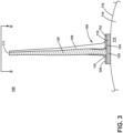
- FIG. 3 is a cross-sectional perspective view of the airfoil assembly 100 taken along line III-III of FIG. 2 .
- the airfoil 108 includes a core 120.
- the yielding interface 118 is a crushable interface 124.
- the crushable interface 124 is formed from a material suitable for deforming under a given target torque load.
- the target torque load can range from 60,000lbf-in to 100,000 lbf-in (6779Nm to 11298Nm).
- the given target torque load is 80,000lbf-in (9039Nm).
- the crushable interface 124 can be defined by a honeycomb ribbon material or an additive matrix.
- the honeycomb ribbon material can be a weaker material than the surrounding structure that will buckle during high loading rates.
- the additive matrix can be an auxetic structure where when stretched, it will thicken and when compressed, it will shrink.
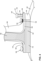
- FIG. 4 is an enlarged cross-sectional perspective view of the airfoil assembly 100.
- the crushable interface 124 is affixed to the platform 102 by a set of bolts 130.
- the platform 102 includes at least one bolt hole 125 for receiving the set of bolts 130.
- the at least one bolt hole 125 can be chamfered.
- the crushable interface 124 can be formed as a disc 123.
- At least one bolt 132, by way of non-limiting example two bolts, in the set of bolts 130 includes a crushable bolt spacer 134.
- the crushable bolt spacer 134 can be a washer or a sleeve enveloping a bolt shaft 133 of the at least one bolt 132.
- the crushable bolt spacer 134 Before tightening the at least one bolt 132, the crushable bolt spacer 134 is in an expanded position, illustrated in dashed line 135, extending along the bolt shaft 133 between a bolt head 137 and the platform 102. When the at least one bolt 132 is tightened down, the crushable bolt spacer 134 deforms and is held between the platform 102 and a bolt head 137.
- the crushable bolt spacer 134 is formed from a yielding material, by way of non-limiting example a metal foam or a metal or composite lattice. Similarly, to the yielding interface 118, the crushable bolt spacer 134 is made from a material suitable for deforming under the given load.
- FIG. 5 is a top-down view of the airfoil assembly 100 from line V-V of FIG. 3 .
- the airfoil assembly 100 is circumferentially arranged about the engine centerline 12 ( FIG 1 ).
- a circumferential direction (denoted “C") is perpendicular to both the radial direction R and the axial direction A.
- Air moves through the turbine engine 10 ( FIG. 1 ) in a flow direction (denoted “F”) generally parallel to the axial direction A.
- An angle of attack (denoted “AOA”) is the angle measurement between the circumferential direction C and the flow direction F.
- the airfoil 108 is a variable pitch airfoil 111 in that it is rotatable about the center point P.
- the amount of rotation is within an arc (denoted " ⁇ ") defined as between 20° and 160° with respect to the circumferential direction C and point P.
- a footprint 129 of where the airfoil 108 meets the platform 102 at the root 110 is illustrated in dashed line. It can more clearly be seen that the variable pitch airfoil 111 is has a changing angle of attack AOA as the airfoil 108 rotates about the center point P, and in turn the central axis CA ( FIG. 2 ).
- the crushable interface 124 includes multiple crushable regions 126, by way of non-limiting example a first crushable region 126a and a second crushable region 126b, though any number of crushable regions 126 is contemplated. While the crushable regions 126 are illustrated as being separated by a border 127 running parallel to the circumferential direction C, it should be understood that the border 127 could be curved or angled.
- the crushable regions 126 have variable stiffness each having different hardness levels. Materials with variable stiffness could be implemented by using lattice cell structures having different sizes. Varying a metal to void ratio by volume of a metal foam can also vary the stiffness. Further, different base materials can be utilized for the metal foam such as stainless steel, aluminum, titanium, etc.
- the lattice cell structures could also be formed in a cubic cell structure, or a hexagonal cell structure, or could implemented as an auxetic lattice structure.
- FIG. 6 is a cross-sectional view of a yielding interface 218 according to another aspect of the disclosure herein.
- the yielding interface 218 is provided within an airfoil assembly 200 substantially similar to the airfoil assembly 100 of FIGS. 2-5 , therefore, like parts will be identified with like numerals increased by 100. It should be understood that the description of the like parts of the yielding interface 118 applies to the yielding interface 218 unless otherwise noted.
- the airfoil assembly 200 includes a platform 202 having an inner surface 204 and an outer surface 206.
- An airfoil 208 extends from the outer surface 206 in the radial direction R.
- the airfoil 208 extends from a root 210 to a tip (not shown).
- the airfoil 208 extends between an airfoil leading edge 212 and an airfoil trailing edge 213.
- the yielding interface 218 extends axially between an interface leading edge 217 and an interface trailing edge 219.
- the yielding interface 218 includes a tapered portion 224 that tapers from a small thickness (denoted "TS") defining a thin end 223 proximate the interface leading edge 217 toward a full thickness (denoted "TF") defining a thick end 225 of the yielding interface 218 at or near the interface trailing edge 219.
- a tapered base 236 extends from the small thickness TS of the tapered portion 224 proximate the interface leading edge 217 toward the full thickness TF of the tapered portion 224 proximate the interface trailing edge 219. In other words, the tapered base 236 mirrors the tapered portion 224.
- the tapered portion 224 can be formed from a honeycomb ribbon material or an additive matrix.
- the additive matrix can be an auxetic structure where when stretched, it thickens and when compressed, it shrinks.
- the tapered base 236 is formed from a hard metallic, a flexible dense polymer, or a hard rubber.
- the tapered base 236 can also have a consistent or variable durometer. A consistent durometer can be achieved by utilizing a single material, whereas a variable durometer can be achieved by a mixture of materials, including such materials as neoprene or silicone rubber or a combination of both including a transition between both materials.
- FIG. 7 is a cross-sectional top-down view of a yielding interface 318 according to another aspect of the disclosure herein.
- the yielding interface 318 is substantially similar to the yielding interface 118 ( FIGS. 2-5 ), therefore, like parts will be identified with like numerals increased by 200. It should be understood that the description of the like parts of the yielding interface 118 applies to the yielding interface 318 unless otherwise noted.
- the yielding interface 318 is a disc 323 formed completely from a crushable material and defines a crushable interface 324.
- the crushable material can be a honeycomb ribbon material or an additive matrix.
- the additive matrix can be an auxetic structure where when stretched, it thickens and when compressed, it shrinks.
- FIG. 8 is a cross-sectional top-down view of a yielding interface 418 according to another aspect of the disclosure herein.
- the yielding interface 418 is substantially similar to the yielding interface 118 ( FIGS. 2-5 ), therefore, like parts will be identified with like numerals increased by 300. It should be understood that the description of the like parts of the yielding interface 118 applies to the yielding interface 418 unless otherwise noted.
- the yielding interface 418 is a disc 423 with over 50% of a crushable material defining a crushable interface 424.
- the yielding interface 418 extends axially between an interface leading edge 417 and an interface trailing edge 419.
- the crushable material can be distributed unevenly circumferentially.
- An uneven distribution 438 provides a crushable portion support for the airfoil 108 ( FIG. 5 ) throughout the arc ⁇ .
- the crushable material can be a honeycomb ribbon material or an additive matrix.
- the additive matrix can be an auxetic structure where when stretched, it thickens and when compressed, it shrinks. In some aspects, even after the crushable material has deformed or crushed, the airfoil 108 can still rotate about the central axis CA ( FIG. 2 ).
- a similar distribution of a stiffer material in the yielding interface 318 is provided with the stiffer material proximate the interface trailing edge 419 and the more flexible crushable material proximate the interface leading edge 417.
- the stiffer material defines a base 436.
- the stiffer material can be a hard metallic, a flexible dense polymer, or hard rubber.
- the base 436 can also have a consistent or variable durometer. A consistent durometer can be achieved by utilizing a single material, whereas a variable durometer can be achieved by a mixture of materials, including such materials as neoprene or silicone rubber or a combination of both including a transition between both materials.
- the crushable material defines 83% of the yielding interface 418 and the stiffer material defines 17% of the yielding interface. It is also contemplated that the crushable interface 424 defines an arc ⁇ of between 50° and 130°.
- FIG. 9 is a cross-sectional view of a yielding interface 518 according to another aspect of the disclosure herein.
- the yielding interface 518 is substantially similar to the yielding interface 418 ( FIG. 8 ), therefore, like parts will be identified with like numerals increased by 100. It should be understood that the description of the like parts of the yielding interface 418 applies to the yielding interface 518 unless otherwise noted.
- the yielding interface 518 is a disc 523 made up of a crushable material defining a crushable interface 524.
- the yielding interface 518 extends axially between an interface leading edge 517 and an interface trailing edge 519.
- the crushable material can be distributed unevenly circumferentially.
- An uneven distribution 538 provides a crushable portion support for the airfoil 108 ( FIG. 5 ) throughout the arc ⁇ .
- the crushable material defines 67% of the yielding interface 518.
- a remaining portion of the yielding interface 518 is made up of a stiffer material defining a base 536.
- the stiffer material defines 33% of the yielding interface 518. It should be understood that the amount of crushable material vs stiffer material can vary depending on the arc ⁇ .
- the crushable interface 524 defines an arc ⁇ of between 20° and 160°.
- FIG. 10 is a cross-sectional view of a yielding interface 618 according to another aspect of the disclosure herein.
- the yielding interface 618 is provided within an airfoil assembly 600 substantially similar to the airfoil assembly 100 ( FIGS. 2-5 ), therefore, like parts will be identified with like numerals increased by 500. It should be understood that the description of the like parts of the airfoil assembly 100 applies to the airfoil assembly 600 unless otherwise noted.
- the airfoil assembly 600 includes a platform 602 having an inner surface 604 and an outer surface 606.
- An airfoil 608 extends from the outer surface 606.
- the airfoil 608 extends from a root 610 to a tip (not shown).
- the airfoil 608 extends between an airfoil leading edge 612 and an airfoil trailing edge 613.
- the yielding interface 618 extends axially between an interface leading edge 617 and an interface trailing edge 619.
- the yielding interface 618 is a spring 640 compressible in the radial direction R.
- the spring 640 can be a Belleville washer 642a oriented in a first direction opening toward a mounting structure 614 of the airfoil assembly 600.
- the spring 640 is a Belleville washer 642b oriented in a second direction opposite the first direction and opening toward the inner surface 604 of the platform 602 of the airfoil assembly 600.
- the spring 640 can include any number of springs.
- the Belleville washer 642a, 642b can be stacked to increase or change the stiffness of the spring 640.
- the airfoil assembly 700 includes a platform 702 having an inner surface 704 and an outer surface 706.
- An airfoil 708 extends from the outer surface 706.
- the airfoil 708 extends from a root 710 to a tip (not shown).
- the airfoil 708 extends between an airfoil leading edge 712 and an airfoil trailing edge 713.
- the yielding interface 718 is similar to the yielding interface 218 ( FIG. 6 ).
- the yielding interface 718 extends axially between an interface leading edge 717 and an interface trailing edge 719.
- the yielding interface 718 includes a tapered portion 724 that tapers from a small thickness TS proximate the interface leading edge 717 toward a full thickness TF of the yielding interface 718 at or near the interface trailing edge 719.
- a tapered base 736 extends from the small thickness TS proximate the interface leading edge 717 toward the full thickness TF proximate the interface trailing edge 719.
- the tapered base 736 mirrors the tapered portion 724.
- the tapered portion 724 can be formed from a honeycomb ribbon material or an additive matrix.
- the additive matrix can be an auxetic structure where when stretched, it thickens and when compressed, it shrinks.
- the tapered base 736 is formed from a hard metallic, a flexible dense polymer, or hard rubber.
- the tapered base 736 can also have a consistent or variable durometer.
- a consistent durometer can be achieved by utilizing a single material, whereas a variable durometer can be achieved by a mixture of materials, including such materials as neoprene or silicone rubber or a combination of both including a transition between both materials.
- the yielding interface 718 is affixed to the platform 702 by a set of bolts 730. At least one bolt 731 in the set of bolts 730 is located at a thick end 725 of the yielding interface 718 with at least one spring 740 located under a bolt head 744 of the at least one bolt 730. At least one bolt 732 in the set of bolts 730 includes another spring 740. The spring 740 is located between a bolt head 744 of the at least one bolt 732 and the outer surface 706 of the platform 702. The spring 740 can be a Belleville washer 742a oriented in a first direction opening toward the outer surface 706.
- the spring 740 is a Belleville washer 742b oriented in a second direction opposite the first direction and opening toward the bolt head 744.
- the spring 740 can include any number of springs associated with all or some of the bolts in the set of bolts 730.
- the Belleville washer 742a, 742b can be stacked to increase or change the stiffness of the spring 740.
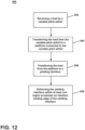
- FIG. 12 a flow chart illustrating a method 500 of reducing a load transfer for any of the airfoil assemblies described herein.
- the method 500 includes at block 502 receiving a load by the airfoil 108 ( FIGS. 2-5 ). Further, at block 504 transferring the load from the airfoil 108 to the platform 102 ( FIGS. 2-5 ) and in turn at block 506 from the platform 102 to the yielding interface 118 ( FIGS. 2-5 ).
- the method can further include at block 508 deforming the yielding interface 118 within at least one region proximate the interface leading edge 117 ( FIGS. 2-5 ) of the yielding interface 118.
- the at least one region can be the first crushable region 126a ( FIGS. 2-5 ) or any region proximate the interface leading edge 117.
- the yielding interface 118 deforms elastically. Elastic deformation enables the yielding interface 118 within the at least one region proximate the interface leading edge 117 to rebound when the load has dissipated.
- the Belleville washers 642a, 642b FIG. 10 deform and then rebound once the load has dissipated.
- the yielding interface 118 deforms inelastically. Inelastic deformation enables the yielding interface 118 to deform permanently under the load.
- Benefits associated with the disclosure herein include reducing load transfer from the airfoil to the mounting structure by absorbing energy through the yielding interface.
- the yielding interface is made of a honeycomb structure that is weaker than the surrounding structure and will buckle during high loading rates.
- the yielding interface includes spacers in the form of crushable material or springs for any mounting bolts in order to accomplish the same load reduction.
- Additional benefits include an overall weight reduction of all mounting hardware of the airfoil while still maintaining safe operation after deformation or crushing of the yielding interface occurs.
- An airfoil assembly for a turbine engine comprising a platform defining an inner surface and an outer surface; a variable pitch airfoil extending radially from the outer surface of the platform, the variable pitch airfoil extending from a root to a tip to define a span length; a mounting structure having a curved mounting surface and defining at least a portion of a hub; and a yielding interface affixed to the platform inner surface and the curved mounting surface, wherein the yielding interface provides yielding in a plurality of directions between the platform and the mounting structure.
- variable pitch airfoil is a fixed variable pitch airfoil.
- the crushable interface comprises multiple crushable regions, each having different hardness levels.
- the crushable interface is a tapered portion comprising a thick end and a thin end.
- the mounting structure comprises at least one bolt hole for receiving the set of bolts, and the at least one bolt hole is chamfered.
- a method of reducing a load transferred through an airfoil assembly comprising receiving a load by a variable pitch airfoil; transferring the load from the variable pitch airfoil to a platform connected to the variable pitch airfoil; transferring the load from the platform to a yielding interface; and deforming the yielding interface within at least one region proximate an interface leading edge of the yielding interface.
- a turbine engine for an aircraft having an airfoil assembly comprising a platform defining an inner surface and an outer surface; a variable pitch airfoil extending radially from the outer surface of the platform, the variable pitch airfoil extending from a root to a tip to define a span length; a mounting structure having a curved mounting surface and defining at least a portion of a hub; and a yielding interface affixed to the platform inner surface and the curved mounting surface, wherein the yielding interface provides yielding in a plurality of directions between the platform and the mounting structure.
- variable pitch airfoil is a fixed variable pitch airfoil.
- the crushable interface comprises multiple crushable regions, each having different hardness levels.
- the crushable interface is a tapered portion comprising a thick end and a thin end.
- the mounting structure comprises at least one bolt hole for receiving the set of bolts, and the at least one bolt hole is chamfered.
Landscapes
- Engineering & Computer Science (AREA)
- Mechanical Engineering (AREA)
- General Engineering & Computer Science (AREA)
- Chemical & Material Sciences (AREA)
- Materials Engineering (AREA)
- Composite Materials (AREA)
- Structures Of Non-Positive Displacement Pumps (AREA)
Applications Claiming Priority (1)
| Application Number | Priority Date | Filing Date | Title |
|---|---|---|---|
| US18/386,867 US12234745B1 (en) | 2023-11-03 | 2023-11-03 | Variable pitch airfoil |
Publications (1)
| Publication Number | Publication Date |
|---|---|
| EP4553291A1 true EP4553291A1 (de) | 2025-05-14 |
Family
ID=93213903
Family Applications (1)
| Application Number | Title | Priority Date | Filing Date |
|---|---|---|---|
| EP24207474.8A Pending EP4553291A1 (de) | 2023-11-03 | 2024-10-18 | Verstellbares schaufelblatt |
Country Status (2)
| Country | Link |
|---|---|
| US (2) | US12234745B1 (de) |
| EP (1) | EP4553291A1 (de) |
Citations (5)
| Publication number | Priority date | Publication date | Assignee | Title |
|---|---|---|---|---|
| US2727716A (en) * | 1945-12-21 | 1955-12-20 | Power Jets Res & Dev Ltd | Bladed body |
| US7824152B2 (en) * | 2007-05-09 | 2010-11-02 | Siemens Energy, Inc. | Multivane segment mounting arrangement for a gas turbine |
| US20130149139A1 (en) * | 2011-12-08 | 2013-06-13 | Thomas Tracy Wallace | Dynamic load reduction system |
| EP3232005B1 (de) * | 2016-04-15 | 2019-03-06 | Rolls-Royce Corporation | Turbinenschaufel mit einem lastverteilungssystem mit nachgiebiger schicht |
| FR3082555A1 (fr) * | 2018-06-18 | 2019-12-20 | Safran Aircraft Engines | Roue d'aubes redresseuses d'un moteur d'aeronef, tel qu'un turboreacteur |
Family Cites Families (11)
| Publication number | Priority date | Publication date | Assignee | Title |
|---|---|---|---|---|
| GB995228A (en) * | 1964-05-08 | 1965-06-16 | Rolls Royce | Bladed structure, for example, for a gas turbine engine compressor |
| US4019832A (en) * | 1976-02-27 | 1977-04-26 | General Electric Company | Platform for a turbomachinery blade |
| US5281096A (en) * | 1992-09-10 | 1994-01-25 | General Electric Company | Fan assembly having lightweight platforms |
| US5282720A (en) | 1992-09-15 | 1994-02-01 | General Electric Company | Fan blade retainer |
| JP4494658B2 (ja) | 2001-02-06 | 2010-06-30 | 三菱重工業株式会社 | ガスタービンの静翼シュラウド |
| US8851854B2 (en) | 2011-12-16 | 2014-10-07 | United Technologies Corporation | Energy absorbent fan blade spacer |
| FR2989977B1 (fr) | 2012-04-26 | 2014-05-23 | Snecma | Ebauche fibreuse tissee en une seule piece par tissage tridimensionnel pour la realisation d'une plate-forme a caisson ferme pour soufflante de turbomachine en materiau composite |
| US11168572B2 (en) | 2019-02-05 | 2021-11-09 | Raytheon Technologies Corporation | Composite gas turbine engine component |
| US11092021B2 (en) | 2019-05-06 | 2021-08-17 | Raytheon Technologies Corporation | Fan platform with core and skin |
| FR3109794B1 (fr) | 2020-05-04 | 2022-08-12 | Safran Aircraft Engines | Plateforme pour un rotor de soufflante d’une turbomachine d’aéronef |
| US11970957B2 (en) * | 2021-08-19 | 2024-04-30 | General Electric Company | Acoustic turbofan airfoil apparatus |
-
2023
- 2023-11-03 US US18/386,867 patent/US12234745B1/en active Active
-
2024
- 2024-10-18 EP EP24207474.8A patent/EP4553291A1/de active Pending
-
2025
- 2025-01-22 US US19/033,948 patent/US12492641B2/en active Active
Patent Citations (5)
| Publication number | Priority date | Publication date | Assignee | Title |
|---|---|---|---|---|
| US2727716A (en) * | 1945-12-21 | 1955-12-20 | Power Jets Res & Dev Ltd | Bladed body |
| US7824152B2 (en) * | 2007-05-09 | 2010-11-02 | Siemens Energy, Inc. | Multivane segment mounting arrangement for a gas turbine |
| US20130149139A1 (en) * | 2011-12-08 | 2013-06-13 | Thomas Tracy Wallace | Dynamic load reduction system |
| EP3232005B1 (de) * | 2016-04-15 | 2019-03-06 | Rolls-Royce Corporation | Turbinenschaufel mit einem lastverteilungssystem mit nachgiebiger schicht |
| FR3082555A1 (fr) * | 2018-06-18 | 2019-12-20 | Safran Aircraft Engines | Roue d'aubes redresseuses d'un moteur d'aeronef, tel qu'un turboreacteur |
Also Published As
| Publication number | Publication date |
|---|---|
| US20250163815A1 (en) | 2025-05-22 |
| US12234745B1 (en) | 2025-02-25 |
| US12492641B2 (en) | 2025-12-09 |
Similar Documents
| Publication | Publication Date | Title |
|---|---|---|
| US6382905B1 (en) | Fan casing liner support | |
| US12140040B2 (en) | Airfoil assembly with a differentially oriented stage | |
| US20240309769A1 (en) | Outlet guide vane assembly for a turbofan engine | |
| US12291980B2 (en) | Unducted rectifier for a turbomachine, turbomachine module and aircraft turbomachine | |
| US20230193945A1 (en) | Bolt assembly | |
| US12535007B2 (en) | Cover plate connections for a hollow fan blade | |
| US20210221491A1 (en) | Fuselage shield for an aircraft with an unducted engine | |
| CN116624433A (zh) | 减少翼型件的偏转的方法和设备 | |
| US10654577B2 (en) | Rainbow flowpath low pressure turbine rotor assembly | |
| US11879354B2 (en) | Rotor blade with frangible spar for a gas turbine engine | |
| US12276199B2 (en) | Outlet guide vane assembly for a turbofan engine | |
| EP3702625B1 (de) | Eiskristallschutz für ein gasturbinentriebwerk | |
| US11814174B2 (en) | Layered fuselage shield | |
| EP4553291A1 (de) | Verstellbares schaufelblatt | |
| US20260071550A1 (en) | Variable pitch airfoil | |
| EP3581499B1 (de) | Gasturbinenmotor | |
| US20230258092A1 (en) | Part-span shrouds for pitch controlled aircrafts | |
| EP3287601B1 (de) | Mehrteilige nichtlineare bläserschaufel | |
| US12018586B2 (en) | Airfoil assembly with tensioned blade segments | |
| GB2586269A (en) | A variable guide vane system | |
| US20250290424A1 (en) | Metallic blade spar retention system | |
| US20260036064A1 (en) | Crushable bearing ring for a fan assembly | |
| US20250223909A1 (en) | Outlet guide vane assembly for a turbofan engine | |
| US12565855B1 (en) | Gas turbine engine | |
| US11773732B2 (en) | Rotor blade with protective layer |
Legal Events
| Date | Code | Title | Description |
|---|---|---|---|
| PUAI | Public reference made under article 153(3) epc to a published international application that has entered the european phase |
Free format text: ORIGINAL CODE: 0009012 |
|
| STAA | Information on the status of an ep patent application or granted ep patent |
Free format text: STATUS: THE APPLICATION HAS BEEN PUBLISHED |
|
| AK | Designated contracting states |
Kind code of ref document: A1 Designated state(s): AL AT BE BG CH CY CZ DE DK EE ES FI FR GB GR HR HU IE IS IT LI LT LU LV MC ME MK MT NL NO PL PT RO RS SE SI SK SM TR |
|
| STAA | Information on the status of an ep patent application or granted ep patent |
Free format text: STATUS: REQUEST FOR EXAMINATION WAS MADE |
|
| 17P | Request for examination filed |
Effective date: 20251112 |