EP4553283A1 - Turbinenmotor mit schaufel mit kühllöchern - Google Patents
Turbinenmotor mit schaufel mit kühllöchern Download PDFInfo
- Publication number
- EP4553283A1 EP4553283A1 EP24211878.4A EP24211878A EP4553283A1 EP 4553283 A1 EP4553283 A1 EP 4553283A1 EP 24211878 A EP24211878 A EP 24211878A EP 4553283 A1 EP4553283 A1 EP 4553283A1
- Authority
- EP
- European Patent Office
- Prior art keywords
- cooling
- blade assembly
- airfoil
- engine
- inlet
- Prior art date
- Legal status (The legal status is an assumption and is not a legal conclusion. Google has not performed a legal analysis and makes no representation as to the accuracy of the status listed.)
- Pending
Links
Images


Classifications
-
- F—MECHANICAL ENGINEERING; LIGHTING; HEATING; WEAPONS; BLASTING
- F01—MACHINES OR ENGINES IN GENERAL; ENGINE PLANTS IN GENERAL; STEAM ENGINES
- F01D—NON-POSITIVE DISPLACEMENT MACHINES OR ENGINES, e.g. STEAM TURBINES
- F01D5/00—Blades; Blade-carrying members; Heating, heat-insulating, cooling or antivibration means on the blades or the members
- F01D5/12—Blades
- F01D5/14—Form or construction
- F01D5/18—Hollow blades, i.e. blades with cooling or heating channels or cavities; Heating, heat-insulating or cooling means on blades
- F01D5/186—Film cooling
-
- F—MECHANICAL ENGINEERING; LIGHTING; HEATING; WEAPONS; BLASTING
- F01—MACHINES OR ENGINES IN GENERAL; ENGINE PLANTS IN GENERAL; STEAM ENGINES
- F01D—NON-POSITIVE DISPLACEMENT MACHINES OR ENGINES, e.g. STEAM TURBINES
- F01D5/00—Blades; Blade-carrying members; Heating, heat-insulating, cooling or antivibration means on the blades or the members
- F01D5/12—Blades
- F01D5/14—Form or construction
- F01D5/18—Hollow blades, i.e. blades with cooling or heating channels or cavities; Heating, heat-insulating or cooling means on blades
- F01D5/187—Convection cooling
-
- F—MECHANICAL ENGINEERING; LIGHTING; HEATING; WEAPONS; BLASTING
- F05—INDEXING SCHEMES RELATING TO ENGINES OR PUMPS IN VARIOUS SUBCLASSES OF CLASSES F01-F04
- F05D—INDEXING SCHEME FOR ASPECTS RELATING TO NON-POSITIVE-DISPLACEMENT MACHINES OR ENGINES, GAS-TURBINES OR JET-PROPULSION PLANTS
- F05D2240/00—Components
- F05D2240/20—Rotors
- F05D2240/30—Characteristics of rotor blades, i.e. of any element transforming dynamic fluid energy to or from rotational energy and being attached to a rotor
- F05D2240/307—Characteristics of rotor blades, i.e. of any element transforming dynamic fluid energy to or from rotational energy and being attached to a rotor related to the tip of a rotor blade
-
- F—MECHANICAL ENGINEERING; LIGHTING; HEATING; WEAPONS; BLASTING
- F05—INDEXING SCHEMES RELATING TO ENGINES OR PUMPS IN VARIOUS SUBCLASSES OF CLASSES F01-F04
- F05D—INDEXING SCHEME FOR ASPECTS RELATING TO NON-POSITIVE-DISPLACEMENT MACHINES OR ENGINES, GAS-TURBINES OR JET-PROPULSION PLANTS
- F05D2260/00—Function
- F05D2260/20—Heat transfer, e.g. cooling
- F05D2260/202—Heat transfer, e.g. cooling by film cooling
Definitions
- the present subject matter relates generally to a blade assembly for a turbine engine, and more specifically to a turbine engine having an airfoil with cooling holes.
- a gas turbine engine typically includes a turbomachine, with a fan in some implementations.
- the turbomachine generally includes a compressor, combustor, and turbine in serial flow arrangement.
- the compressor compresses air which is channeled to the combustor where it is mixed with fuel.
- the mixture is then ignited to generate hot combustion gases.
- the combustion gases are channeled to the turbine, which extracts energy from the combustion gases for powering the compressor and fan, if used, as well as for producing useful work to propel an aircraft in flight or to power a load, such as an electrical generator.
- various systems During operation of the gas turbine engine, various systems generate a relatively large amount of heat and stress. For example, a substantial amount of heat or stress can be generated during operation of the thrust generating systems, lubrication systems, electric motors and/or generators, hydraulic systems or other systems.
- a design that mitigates heat loads and/or stresses on an engine component is advantageous.
- the blade assembly may be a blade assembly in a turbine section of a gas turbine engine.
- the blade assembly may be a stage one blade assembly of a high pressure turbine, which typically experiences the highest thermal and mechanical stresses.
- the blade assembly includes a shank and a platform.
- the shank is used to attach the blade assembly to a turbine disk.
- the shank is formed as a dovetail received in the turbine disk.
- the platform of the blade assembly together with other circumferentially arranged platforms and seals of other blade assemblies, defines a continuous annular ring that prevents and/or reduces hot gas leakage into the turbine disk cavity and/or a stator ring of the gas turbine engine.
- the airfoil extends radially from the platform, away from the turbine disk, while the shank extends radially from the platform, toward the turbine disk.
- cooling conduits in the blade assembly create stress concentrations.
- the size of the cooling conduits affects the thickness of the airfoil wall, which affects stress concentrations in the airfoil. Relatively large stresses can contribute to an unexpected or premature part replacement. Therefore, there is a need for a blade assembly with greater durability to increase time on wing.
- connection references e.g., attached, coupled, connected, and joined are to be construed broadly and can include intermediate structural elements between a collection of elements and relative movement between elements unless otherwise indicated. As such, connection references do not necessarily infer those two elements are directly connected and in fixed relation to one another.
- the exemplary drawings are for the purposes of illustration only and the dimensions, positions, order, and relative sizes reflected in the drawings attached hereto can vary.
- a "stage" of either a compressor or a turbine of a gas turbine engine is a set of blade assemblies and an adjacent set of vane assemblies, with both sets of the blade assemblies and the vane assemblies circumferentially arranged about an engine centerline.
- a pair of circumferentially-adjacent vanes in the set of vane assemblies are referred to as a nozzle.
- the blade assemblies rotate relative to the engine centerline and, in one example, are mounted to a rotating structure, such as a disk, to affect the rotation.
- the word "exemplary" means "serving as an example, instance, or illustration.” Any implementation described herein as "exemplary” is not necessarily to be construed as preferred or advantageous over other implementations. Additionally, unless specifically identified otherwise, all embodiments described herein should be considered exemplary.
- first,” “second,” “third,” and “fourth” can be used interchangeably to distinguish one component from another and are not intended to signify location or importance of the individual components.
- a "set" or a set of elements can include any number of said elements, including one.
- forward and aft refer to relative positions within a gas turbine engine and refer to the normal operational attitude or direction of travel of the gas turbine engine.
- forward refers to a position relatively closer to the nose of an aircraft and aft refers to a position relatively closer to a tail of the aircraft.
- upstream and downstream refer to a direction with respect to a direction of fluid flow along a flowpath.
- fluid refers to a gas or a liquid and "fluidly coupled” means a fluid can flow between the coupled regions.
- stress refers to the internal force balance within a material that produces strain or deformation of a part subjected to internal (inertial, thermal) or external forces (point or pressure loading).
- a yield stress occurs, a part irrecoverably deforms.
- an ultimate stress is exceeded, the material is compromised resulting in material failure. This local material failure would drive a redistribution of loading across the part, which can result in fracture or propagation of a prior existing crack in a part.
- Centrifugal stress refers to stresses on the blade that are primarily caused by centrifugal forces as the blade rotates about the rotational axis.
- Thermal stress refers to stresses resulting from temperature differences between internal and external parts of the blade.
- fatigue refers to a progressive and localized damage of a material under cyclic or fluctuating stress.
- field distress refers to distress observed on hardware in operation which may or may not have been observed in component testing.
- creep refers to a slow and/or continuous deformation of a material under a constant stress.
- a radial direction is a direction that is perpendicular to a base plane on a shank of a blade assembly.
- an axial direction is a direction that is perpendicular to a shank leading-edge plane on the shank of the blade assembly.
- a tangential direction is a direction that is perpendicular to the radial direction and the axial direction.
- cooling conduit refers to a conduit formed in the airfoil.
- set of cooling holes refers to a number of cooling holes located proximate the tip of the airfoil.
- a cooling passage length (denoted L ) as used herein is the length of a cooling passage of a single cooling hole in the set of cooling holes measured from along the centerline of the cooling passage between an inlet of the cooling passage to an outlet of the cooling passage.
- An average cooling passage length (denoted L avg and also referred to as an average bore length) as used herein is an average of all lengths L of the respective cooling passages associated with each cooling hole in the set of cooling holes.
- a number (denoted N ) as used herein is a number of cooling holes in the set of cooling holes.
- a stator rotor seal radius (denoted SRSR ) is a radius of curvature of an upper edge of a stator rotor seal on a blade assembly.
- redline exhaust gas temperature refers to a maximum permitted takeoff temperature documented in a Federal Aviation Administration ("FAA”)-type certificate data sheet.
- FAA Federal Aviation Administration
- redline EGT may refer to a maximum permitted takeoff temperature of an airflow after a first stage stator downstream of an HP turbine of an engine that the engine is rated to withstand.
- redline EGT is sometimes also referred to as an indicated turbine exhaust gas temperature or indicated turbine temperature.
- core speed refers to a maximum rotational speed of the turbine engine permitted at takeoff as documented in the FAA-type certificate data sheet.
- core speed CS is a maximum rate at which the drive shaft for the turbine engine rotates, which defines the rotational speed of the particular blade within the engine.
- core speed is sometimes also referred to as a redline core speed.
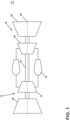
- FIG. 1 is a schematic view of a gas turbine engine 10.
- the gas turbine engine 10 can be used within an aircraft.
- the gas turbine engine 10 includes an engine core extending along an engine centerline 20 and including, at least, a compressor section 12, a combustor 14, and a turbine section 16 in serial flow arrangement.
- the gas turbine engine 10 includes a fan (not shown) that is driven by the engine core to produce thrust and provide air to the compressor section 12.
- the gas turbine engine 10 includes a drive shaft 18 that rotationally couples the fan, compressor section 12, and turbine section 16, such that rotation of one affects the rotation of the others and defines a rotational axis along the engine centerline 20 of the gas turbine engine 10.
- the compressor section 12 includes a low-pressure (LP) compressor 22 and a high-pressure (HP) compressor 24 serially fluidly coupled to one another.
- the turbine section 16 includes an HP turbine 26 and an LP turbine 28 serially fluidly coupled to one another.
- the drive shaft 18 operatively couples the LP compressor 22, the HP compressor 24, the HP turbine 26 and the LP turbine 28 to one another.
- the drive shaft 18 includes an LP drive shaft (not illustrated) and an HP drive shaft (not illustrated), where the LP drive shaft couples the LP compressor 22 to the LP turbine 28, and the HP drive shaft couples the HP compressor 24 to the HP turbine 26.
- the HP turbine 26 of the engine 10 which operates at high temperatures and where blade assemblies 30 rotates at high angular velocities, prioritizes design aspects for stress mitigation. Both the extreme temperature environment and the high rotational speeds are primary contributors to the high stress levels in turbine blades.
- the temperature environment for the engine 10 may be represented by the redline exhaust gas temperature ( EGT ) and the redline core speed (CS).
- the compressor section 12 includes a plurality of axially spaced stages. Each stage includes a set of circumferentially-spaced rotating blade assemblies and a set of circumferentially-spaced stationary vane assemblies.
- the compressor blade assemblies for a stage of the compressor section 12 are mounted to a disk, which is mounted to the drive shaft 18. Each set of blade assemblies for a given stage can have its own disk.
- the vane assemblies of the compressor section 12 are mounted to a casing which extends circumferentially about the gas turbine engine 10. In a counter-rotating turbine engine, the vane assemblies are mounted to a drum, which is similar to the casing, except the drum rotates in a direction opposite the blade assemblies, whereas the casing is stationary. It will be appreciated that the representation of the compressor section 12 is merely schematic. The number of stages can vary.
- the turbine section 16 includes a plurality of axially spaced stages, with each stage having a set of circumferentially-spaced, rotating blade assemblies and a set of circumferentially-spaced, stationary vane assemblies.
- the turbine blade assemblies for a stage of the turbine section 16 are mounted to a disk which is mounted to the drive shaft 18.
- Each set of blade assemblies for a given stage can have its own disk.
- the vane assemblies of the turbine section are mounted to the casing in a circumferential manner.
- the vane assemblies can be mounted to a drum, which is similar to the casing, except the drum rotates in a direction opposite the blade assemblies, whereas the casing is stationary.
- the number of blade assemblies, vane assemblies and turbine stages can vary.
- the combustor 14 is provided serially between the compressor section 12 and the turbine section 16.
- the combustor 14 is fluidly coupled to at least a portion of the compressor section 12 and the turbine section 16 such that the combustor 14 at least partially fluidly couples the compressor section 12 to the turbine section 16.
- the combustor 14 is fluidly coupled to the HP compressor 24 at an upstream end of the combustor 14 and to the HP turbine 26 at a downstream end of the combustor 14.
- ambient or atmospheric air is drawn into the compressor section 12 via the fan, upstream of the compressor section 12, where the air is compressed defining a pressurized air.
- the pressurized air then flows into the combustor 14 where the pressurized air is mixed with fuel and ignited, thereby generating hot combustion gases.
- Some work is extracted from these combustion gases by the HP turbine 26, which drives the HP compressor 24.
- the combustion gases are discharged into the LP turbine 28, which extracts additional work to drive the LP compressor 22, and the exhaust gas is ultimately discharged from the gas turbine engine 10 via an exhaust section (not illustrated) downstream of the turbine section 16.
- the driving of the LP turbine 28 drives the LP spool to rotate the fan and the LP compressor 22.
- the pressurized airflow and the combustion gases together define a working airflow that flows through the fan, compressor section 12, combustor 14, and turbine section 16 of the gas turbine engine 10.
- the turbine section 16 includes a set of blade assemblies 30 circumferentially mounted to corresponding disks 32.
- the number of individual blade assemblies of the set of blade assemblies 30 mounted to each disk 32 may vary. While shown schematically in FIG. 2 , it should be understood that the turbine section 16 can be a single stage turbine, or can include additional stages as shown.
- Stationary vane assemblies 34 are mounted to a stator ring 36 located distally exterior of each of the disks 32.
- a nozzle 38 is defined by the space between circumferentially-adjacent pairs of vane assemblies 34.
- the number of nozzles 38 provided on the stator ring 36 may vary.
- a flow of hot gas or heated fluid flow exits the combustor 14 and enters the turbine section 16.
- the heated fluid flow HF is directed through the nozzles 28 and impinges on the blade assemblies 30, which rotates the blade assemblies 30 circumferentially around the engine centerline 20 and cause rotation of the drive shaft 18.
- FIG. 3A is a perspective view of a single blade assembly 30 for the gas turbine engine 10 ( FIG. 1 ).
- the blade assembly 30 may correspond to a stage one blade assembly of the HP turbine 26.
- the blade assembly 30 includes a shank 40, a platform 50, and an airfoil 60 (also referred to as a blade or blade portion) extending outward from the platform 50.
- the blade assembly 30 can be constructed as a single unitary part or component (e.g., a monolithic structure).
- the shank 40, the platform 50, and/or the airfoil 60 can be constructed as separate parts or components that are coupled together to form the blade assembly 30.
- FIG. 3A A directional reference system is illustrated in FIG. 3A .
- the shank 40 extends between a base 42 and the platform 50.
- the base 42 of the shank 40 is a flat surface that defines a plane, referred to herein as the base plane (denoted "BP").
- a radial direction (denoted “R") of the blade assembly 30 is a direction that is perpendicular to the base plane BP.
- the shank 40 extends between a shank leading-edge 44 and a shank trailing-edge 46.
- the shank leading-edge 33 is a flat surface that defines a plane, referred herein as the shank leading-edge plane (denoted "SLEP").
- An axial direction (denoted “A") of the blade assembly 30 is a direction that is perpendicular to the shank leading-edge plane SLEP.
- a tangential direction (denoted “T”) is a direction perpendicular to both the radial direction R and the axial direction A.
- the shank 40 is configured, by way of non-limiting example as a dovetail 47, to mount to the disk 32 ( FIG. 2 ) of the engine 10 in order to rotatably drive the blade assembly 30.
- the shank 40 includes a set of inlet passages 48 for receiving a cooling fluid (denoted "CF") for cooling the blade assembly 30.
- CF cooling fluid
- the airfoil 60 extends radially outward from the platform 50 to define a root 61, connected to the platform 50, and a tip 62 opposite the root 61. Additionally, the airfoil 60 includes an outer wall 63 defining an exterior surface 59 defining including a pressure side 64 and a suction side 65 opposite the pressure side 64. The airfoil 60 extends between an airfoil leading-edge 66 and an airfoil trailing-edge 67 downstream from the airfoil leading-edge 66. The airfoil leading-edge 66 and the airfoil trailing-edge 67 separate the pressure side 64 from the suction side 65.
- a set of cooling conduits e.g., the cooling conduits 68 of FIGS.
- a set of cooling holes 90 is formed proximate the tip 62a to fluidly couple the set of cooling conduits within airfoil 60 of the blade assembly 30 to an exterior of the blade assembly 30, as further described below in conjunction with FIGS. 4-7 .
- the cooling holes 92 are near the airfoil trailing-edge 67 along the pressure side 64. In other examples, the cooling holes 92 can be disposed in other locations.
- the plurality of cooling conduits 70 can include multiple conduits that extend radially through the airfoil 60. In some examples, one or more of the cooling conduits 70 are fluidly coupled to certain ones of the inlet passages 481, 48m, 48t.
- the platform 50 has a first surface 51, referred to as an upper surface, and a second surface 52, referred to as a lower surface, opposite the upper surface 51.
- the airfoil 60 extends radially outward from the upper surface 51, and the shank 40 extends radially inward from the lower surface 52 to the base 42.
- the platform 50 extends between a platform leading-edge 53 and a platform trailing-edge 54, opposite the platform leading-edge 53, in the axial direction.
- the platform 50 further extends between a first slashface 55 and a second slashface 56, opposite the first slashface 55, in the tangential direction.
- consecutive blade assemblies 30 are arranged in the circumferential direction C about the engine centerline 20 ( FIG. 1 ) with sequential slashfaces 55, 56 facing each other.
- the heated fluid flow HF flows along the blade assembly 30.
- the airfoil leading-edge 66 is defined by a stagnation point with respect to the heated fluid flow HF.
- the heated fluid flow HF flows generally in the axial direction, from forward to aft, while the local directionality can vary as the heated fluid flow HF is driven or turned within the engine 10.
- the cooling fluid flow CF is supplied to the plurality of inlet passages 48 and flows into the plurality of cooling conduits 68 of FIGS. 5-7 to cool the airfoil 60.
- the cooling fluid flow CF is provided throughout the airfoil 60 and exhausted from the plurality of cooling conduits 68 of FIGS. 5-7 via the cooling holes 90 as a cooling film.
- the platform 50 helps to radially contain the heated fluid flow HF to protect the disk 32 ( FIG. 2 ).
- the platform 50 acts to seal the space radially inward of the platform 50 between the flow path of the heated fluid flow H and the disk 32.
- the disk 32 requires significant cooling to ensure the durability of the HP turbine 26 components.
- Materials used to form the blade assembly 30 include, but are not limited to, steel, refractory metals such as titanium, or superalloys based on nickel, cobalt, or iron, ceramic matrix composites, or combinations thereof.
- the structures can be formed by a variety of methods, including additive manufacturing, casting, electroforming, or direct metal laser melting, in non-limiting examples.
- the platform 50 has a stator rotor seal 57 that extends axially forward from the platform leading-edge 53.
- the stator rotor seal 57 facilitates sealing of a forward buffer cavity (not shown) defined within the rotor assembly.
- the stator rotor seal 57 has an upper surface 300, a lower surface 301 opposite the upper surface 300, and a forward surface 302 between the upper surface 300 and the lower surface 301.
- the stator rotor seal 57 has an upper edge 303 between the upper surface 300 and the forward surface 302. The upper edge 303 is curved or arc- shaped.
- the upper edge 303 is curved between a first end point 304 at the first slashface 55 and a second end point 305 at the second slashface 56.
- the upper edge 303 of stator rotor seal 57 has a center point 306 that forms the peak of the arc.
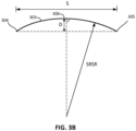
- the upper edge 303 of the stator rotor seal 57 has a radius of curvature, referred to herein as a stator rotor seal radius (denoted "SRSR").
- the center of the radius of curvature may be the engine centerline 20 ( FIG. 1 ). As shown in FIG.
- the SRSR (i.e., the radius of curvature of the upper edge 303 of the stator rotor seal 57) can be calculated using the straight-line distance (S) between the two the end points 304, 305, and the maximum deflection (D), in the radial direction, between the two end points 304, 305 and the center point 306 of the arc.
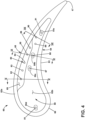
- a top view of the tip plenum 58 illustrates a set of cooling holes 90 that are located at the tip plenum 58 of FIG. 3A .
- the set of cooling holes 90 includes eleven cooling holes with a first cooling hole 81 proximate the leading edge 66 of the airfoil 60.
- a second cooling hole 82, a third cooling hole 83, a fourth cooling hole 84, a fifth cooling hole 85 and a sixth cooling hole 86 are located proximate the suction side 65 and at an elevated portion 69 of the tip wall 62b.
- a seventh cooling hole 87, an eighth cooling hole 88, and a ninth cooling hole 89 are located between the elevated portion 69 and the pressure side 64 within the tip wall 62b.
- a tenth cooling hole 90 and an eleventh cooling hole 91 are located between the pressure side 64 and the suction side 65 proximate the trailing edge 67 of the airfoil 60 within the tip wall 62b.
- the first, seventh, eighth, and eleventh cooling holes 81, 87, 88, 91 are more specifically formed in recessed portions 59a-59d of the tip wall 62b.
- a greater number of the N cooling holes 90 results in a significant volume of cooling flow proximate the tip 62a, which can increase resistance to field distress, but contribute to creep and fatigue in other areas of the airfoil 60 as more cooling fluid proximate the tip 62a means less cooling fluid in remaining portions of the airfoil 60, such as the trailing edge 67 and/or the leading edge.
- a smaller number of the N cooling holes 90 results in less cooling flow, which can provide resistance to creep and fatigue in the other areas but field distress at the tip 62a can increase without sufficient cooling.
- the number of cooling holes 90 and the cooling passage lengths L corresponding to the cooling holes 90 affect creep, fatigue, and field distress. Accordingly, not every number of cooling holes 90 and the cooling passage lengths L will result in a suitable structure, as further described below. An example of a cooling passage is further described below in conjunction with FIGS. 5-7 .
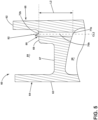
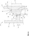
- FIG. 5 is a cross-sectional perspective view of the airfoil 60 taken along line V-V of FIG. 4 .
- the elevated portion 69 can more clearly be seen as defining a surface that is closer to the tip 62a than the tip wall 62b.
- the second cooling hole 82 includes a second cooling passage 70b that extends from a second inlet 71b to a second outlet 72b corresponding to a second cooling passage length L2.
- the cooling passage length L2 is defined as the distance from the center of the second inlet 71b to the center of the second outlet 72b.
- the second inlet 71b is fluidly coupled to the set of cooling conduits 68 and the second outlet 72b is located at the elevated portion 69.
- the second cooling passage 70b defines a second centerline CL2.
- the second centerline CL2 forms a second angle ⁇ 2 with the elevated portion 69.
- the cooling passage length L2 is a distance measured along the second centerline CL2 between the second inlet 71b and the second outlet
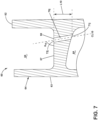
- FIG. 6 is a cross-sectional perspective view of the airfoil 60 taken along line VI-VI of FIG. 4 .
- the fifth cooling hole 85 includes a fifth cooling passage 70e that extends from a fifth inlet 71e to a fifth outlet 72e a fifth cooling passage length L5.
- the cooling passage length L5 is defined as the distance from the center of the fifth inlet 71e to the center of the fifth outlet 72e.
- the fifth inlet 71e is fluidly coupled to the set of cooling conduits 68 and the fifth outlet 72e is located at the elevated portion 69.
- the fifth cooling passage 70e defines a fifth centerline CL5.
- the fifth centerline CL5 forms a fifth angle ⁇ 5 with the elevated portion 69.
- the recessed portion 59 can more clearly be seen as defining a surface that is further from the tip 62a than the tip wall 62b.
- the eighth cooling hole 88 includes an eighth cooling passage 70h that extends from an eighth inlet 71h to an eighth outlet 72h corresponding to an eighth cooling passage length L8.
- the eighth inlet 71h is fluidly coupled to the set of cooling conduits 68 and the eighth outlet 72h is located at the recessed portion 59.
- the eighth cooling passage 70h defines an eighth centerline CL8.
- the eighth centerline CL8 forms an eighth angle ⁇ 8 with the recessed portion 59.
- FIG. 7 is a cross-sectional perspective view of the airfoil 60 taken along line VII-VII of FIG. 4 .
- the tenth cooling hole 90 includes a tenth cooling passage 70j that extends from a tenth inlet 71j to a tenth outlet 72j corresponding to a tenth cooling passage length L10.
- the cooling passage length L10 is defined as the distance from the center of the tenth inlet 71j to the center of the tenth outlet 72j.
- the tenth inlet 71j is fluidly coupled to the set of cooling conduits 68 and the tenth outlet 72j is located at the tip wall 62b.
- the tenth cooling passage 70j defines a tenth centerline CL10.
- the tenth centerline CL10 forms a tenth angle ⁇ 10 with the tip wall
- the blade assemblies 30 of the HP turbine 26 and, specifically, the stage one blade assemblies 30 have the highest flow path temperature of any blade set in the gas turbine engine 10. These stage one blade assemblies also rotate at extremely high angular velocities. The extreme temperature environment and the high rotational speeds impart large forces on the stage one blade assemblies 30 that can lead to creep and fatigue, especially along the suction side of the airfoil. Creep and fatigue may result in an unexpected or premature part replacement that limits engine Time on Wing (TOW). Therefore, there is a need for a blade assembly with high durability that can withstand these large centrifugal stresses and reduce (e.g., minimize) creep and fatigue.
- TOW Time on Wing
- the inventors developed multiple designs and determined that the number of cooling holes in the set of cooling holes 90 and/or the average length L of the cooling passages associated with the set of cooling holes 90 have a significant effect on the durability (e.g., creep and fatigues resistance) of the blade assembly 30 for a given redline EGT and/or redline core speed (CS).
- the inventors determined that the number of cooling holes N in the set of cooling holes 90 and an average of all the lengths of the cooling passages associated with the set of cooling holes 90 proximate the tip 62a affect cooling and durability.
- Decreasing the number of cooling holes N and increasing the average cooling passage length L of the set of cooling holes 90 improves cooling proximate the tip 62a which resulted in a reduction of required cooling fluid which leaves more cooling fluid for remaining portions of the blade assembly 30. Balancing the decrease of the number of cooling holes N with an appropriate average cooling passage length L is necessary in order to provide adequate cooling to the entire blade assembly 30 including the tip 62a.
- the inventors determined during the course of their blade assembly design that the sizes of cross-sectional areas of interior cooling conduits taken along the planes illustrated in FIGS. 6 and 7 and the redline EGT have an effect on the durability of the blade assembly 30.
- Table 1 illustrates eighteen examples (denoted Examples 1-18) of gas turbine engines 10 and blade assemblies 30 developed by the inventors. However, only examples 1-14 yielded desirable solutions to the problem as described above, while examples 15-18 provided results that result in poor performance.
- N represents the number of cooling holes in the set of cooling holes 90 proximate the tip 62a of the blade assembly 30.
- L avg is defined as the sum of the lengths L of the cooling passages associated with each of the eleven cooling holes 81, 82, 83, 84, 85, 86, 87, 88, 89, 90, 91 of FIG. 4 , including the illustrated second cooling passage length L2 ( FIG.
- L avg L 1 + L 2 + L 3 + L 4 + L 5 + L 6 + L 7 + L 8 + L 9 + L 10 + L 11 11
- Table 1 developed by the inventors shown in Table 1 can be characterized by an Expression ( EQ ) and can be used to distinguish those designs in Examples 1-14 and meet the performance (durability) requirements from those designs in Examples 15-18 that do not meet the performance requirements.
- the designs as reflected in Examples 1-14 provide an improved blade assembly better suited for a particular engine operating environment and taking into account the constraints imposed on blade assembly design with cooling holes used in such a system.
- Such designs can be characterized by the below Expression 1 ( EQ ).
- EQ 3.75 1 N L avg 0.01 m ⁇ 1.7 ⁇ EGT ° C 1000 ° C 19391 Hz CS Hz
- EGT represents the maximum operating temperature for the gas turbine engine 10 measured at a particular location within the gas turbine engine 10.
- CS represents the redline core speed of the engine and in turn the rotational speed of the blade assembly 30, measured in units of revolutions per minute, for which the N and L values are determined.
- the redline core speed CS can differ based upon engine design limits and operational parameters such as take-off, climb, and cruise.
- the blade assembly 30 is to rotate at less than or equal to the CS.
- gas turbine engine and blade assembly designs with an EQ value in the range of 3.144 to 18.370 (i.e., 3.144 ⁇ EQ ⁇ 18.370) advantageously meet the durability requirements while remaining within desired tolerances and being capable of use in existing engine systems. While narrowing these multiple factors to a region of possibilities saves time, money, and resources, and the largest benefit is at the system level, where improved airfoils enable improved system performance.
- Benefits are realized when the manufactured component including the blade assembly 30 have a geometry where the above Expression 1 falls within the range 3.144 to 18.370. Such benefits include a reduction in field distress at the tip 62a of the airfoil 60, which increases the lifetime of the blade assembly 30 and therefore extends the time between need for replacement parts. This provides for increased durability for the blade assembly 30, which decreases required maintenance and costs, while increasing overall engine reliability.
- the benefits included herein provide for a blade assembly 30 that fits within existing engines.
- the values for the above Expression 1 as provided herein take existing engines into consideration, permitting replacement of current blade assemblies with replacement blade assemblies (or new blade assemblies) having the parameters of the blade assembly 30 described herein.
- Such consideration provides for replacing and improving current engine systems without requiring the creation of new engine parts capable of holding the blade assembly 30. This provides for improving current engine durability without increasing costs to prepare new engines or further adapt existing engines.
- the below-Table 3 illustrates minimum and maximum values for the number of cooling holes N and the average cooling passage length L as described herein, showing minimum and maximum value ranges for the number of cooling holes N and the average cooling length L based on the preset EGT and/or CS values along with a range of values for Expressions (EQ) suited for blade assembly that meets the durability requirements.
- Engine Element Minimum: Maximum: Units: N Number of Cooling Holes 5 14 n/a L avg Average Length 0.00121 0.00203 Meters (m) EGT Redline Exhaust Gas Temperature 988 1130.313 Degrees Celsius (°C) CS Redline Core Speed 306 353 Hertz (Hz) EQ Expression 1 3.144 18.370 n/a
- Additional benefits associated with the blade assembly 30 with the set of cooling holes 90 described herein include a quick assessment of design parameters in terms of blade size and cooling conduit geometry, engine operational conditions, and blade and vane numbers for engine design and particular blade assembly design. Narrowing these multiple factors to a region of possibilities saves time, money, and resources.
- the blade assembly 30 with the set of cooling holes 90 described herein enables the development and production of high-performance turbine engines and blade assemblies across multiple performance metrics within a given set of constraints.
- Examples 15-16 of Tables 1 and 2 may attempt to increase durability by making sacrifices in terms of weight, aerodynamic performance, and efficiency.
- the standard practice for solving the problem of improving blade assembly durability has been to utilize stronger material.
- such materials lead to increased costs, system weight, and overall space occupied by the blade assembly.
- the overall engine efficiency may be reduced and related components may have to be redesigned to compensate for the stronger materials. In some cases, this result of such a cost-benefit analysis is impractical or impossible. Therefore, a solution for reducing stresses located in airfoils presently used in existing engines is needed, without requiring redesign of related components or without sacrificing overall engine efficiency.
- increasing size of the airfoil or related components, utilizing stronger material, and/or providing additional cooling features can combat centrifugal and thermal stresses.
- increased size, stronger materials, and additional cooling features can lead to increased costs, system weight, overall space occupied by the blade assembly, and performance loss, as well as increased local stresses at the cooling conduits due to increased weight and size relating to the centrifugal forces.
- Increased cooling features results in a relatively less amount of material utilized, which can result in an increase in local stresses at the cooling conduits. Therefore, a solution for reducing stresses at the cooling conduits is needed without otherwise increasing stresses, weight, size, or decreasing engine efficiency.
- Example 1-14 of Tables 1 and 2 provide successful solutions without the need to increase thickness, weight, strength, or the number of cooling features.
- the Example 1-14 of Tables 1-2 illustrate that designs achieve increased durability without penalties to size, weight, strength, or stress through the use of additional cooling features. This is reflected in associated Expression (EQ1) values from 3.144 to 18.370 (i.e., 3.144 ⁇ EQ1 ⁇ 18.370).
- a turbine engine comprising an engine core corresponding to an engine centerline, the engine core including a compressor and a combustor to generate hot combustion gases that have an exhaust gas temperature (EGT) downstream of the combustor, wherein the exhaust gas temperature (EGT) ranges from 988°C to 1120°C, and a blade assembly rotatable about the engine centerline, the blade assembly corresponding to a core speed (CS) wherein the core speed (CS) ranges from 306 Hertz (Hz) to 353 Hz, the blade assembly including a platform including a first surface and a second surface, an airfoil attached to the first surface, the airfoil including a root, a tip and a wall, the wall between a leading-edge and a trailing-edge, the wall between the root and the tip, a set of cooling conduits located within the airfoil, a set of cooling holes located proximate the tip of the airfoil, a
- the turbine engine of any of the proceeding clauses further including a shank attached to the second surface, the shank including a set of inlet passages fluidly coupled to the set of cooling conduits.
- the shank includes a plurality of inlet passages fluidly coupled to the plurality of cooling conduits.
- each of the inlet passages is between a base and one or more of the cooling conduits.
- the plurality of inlet passages includes a leading-edge inlet passage, a middle inlet passage, and a trailing-edge inlet passage.
- a blade assembly for a turbine engine corresponding to an exhaust gas temperature (EGT) ranging from 988°C to example 1130 includes 313°C, the turbine engine including an engine core corresponding to an engine centerline, the engine core to rotate at less than a core speed (CS) ranging from 306 Hertz (Hz) to 353 Hz, the blade assembly connected to the engine core and rotatable about the engine centerline, the blade assembly comprising a platform including a first surface and a second surface, an airfoil attached to the first surface, the airfoil including a root, a tip, and a wall, the wall between a leading-edge and a trailing-edge, the wall between the root and the tip, a set of cooling conduits located within the airfoil, a set of cooling holes located proximate the tip of the airfoil, a cooling hole in the set of cooling holes including a cooling passage corresponding to a cooling passage length (L) between an inlet to an outlet, the inlet fluidly coupled to the set of
- the blade assembly of any of the proceeding clauses further including a shank attached to the second surface, the shank including a set of inlet passages fluidly coupled to the set of cooling conduits.
- the shank includes a plurality of inlet passages fluidly coupled to the plurality of cooling conduits.
- each of the inlet passages is between a base and one or more of the cooling conduits.
- the plurality of inlet passages includes a leading-edge inlet passage, a middle inlet passage, and a trailing-edge inlet passage.
- a blade assembly comprising an airfoil including a tip, a root, and a wall, the wall between a leading-edge and a trailing-edge, the wall between the root and the tip, a set of cooling conduits located within the airfoil, a set of cooling holes located proximate the tip of the airfoil, a cooling hole in the set of cooling holes including a cooling passage corresponding to a cooling passage length (L) corresponding to a distance from an inlet to an outlet, the inlet fluidly coupled to the set of cooling conduits and the outlet located proximate the tip, the set of cooling holes corresponding to a number of cooling holes (N), the number of cooling holes (N) ranging from 5 to 14, and an average cooling passage length (Lavg) based on a sum of the cooling passage length (L) of the cooling passages divided by the number of cooling holes (N), the average cooling passage length (Lavg) ranging from example 0 includes 00121 to example 0 includes 00203 meters, and wherein 3.144
- the blade assembly of any of the proceeding clauses further including a platform including a first surface and a second surface, the airfoil attached to the first surface, and a shank attached to the second surface of the platform, the shank including a set of inlet passages fluidly coupled to the set of cooling conduits.
- the shank includes a plurality of inlet passages fluidly coupled to the plurality of cooling conduits.
- each of the inlet passages is between a base and one or more of the cooling conduits.
- the plurality of inlet passages includes a leading-edge inlet passage, a middle inlet passage, and a trailing-edge inlet passage.
Landscapes
- Engineering & Computer Science (AREA)
- Mechanical Engineering (AREA)
- General Engineering & Computer Science (AREA)
- Turbine Rotor Nozzle Sealing (AREA)
Applications Claiming Priority (2)
| Application Number | Priority Date | Filing Date | Title |
|---|---|---|---|
| US202363597837P | 2023-11-10 | 2023-11-10 | |
| US202463686065P | 2024-08-22 | 2024-08-22 |
Publications (1)
| Publication Number | Publication Date |
|---|---|
| EP4553283A1 true EP4553283A1 (de) | 2025-05-14 |
Family
ID=93460420
Family Applications (2)
| Application Number | Title | Priority Date | Filing Date |
|---|---|---|---|
| EP24211861.0A Pending EP4553282A1 (de) | 2023-11-10 | 2024-11-08 | Turbinenmotor mit schaufel mit kühllöchern |
| EP24211878.4A Pending EP4553283A1 (de) | 2023-11-10 | 2024-11-08 | Turbinenmotor mit schaufel mit kühllöchern |
Family Applications Before (1)
| Application Number | Title | Priority Date | Filing Date |
|---|---|---|---|
| EP24211861.0A Pending EP4553282A1 (de) | 2023-11-10 | 2024-11-08 | Turbinenmotor mit schaufel mit kühllöchern |
Country Status (1)
| Country | Link |
|---|---|
| EP (2) | EP4553282A1 (de) |
Citations (3)
| Publication number | Priority date | Publication date | Assignee | Title |
|---|---|---|---|---|
| US6224336B1 (en) * | 1999-06-09 | 2001-05-01 | General Electric Company | Triple tip-rib airfoil |
| EP1443178B1 (de) * | 2003-01-31 | 2010-06-02 | United Technologies Corporation | Turbinenschaufel |
| EP1760267B1 (de) * | 2005-08-31 | 2013-10-23 | General Electric Company | Turbinenrotorschaufel |
-
2024
- 2024-11-08 EP EP24211861.0A patent/EP4553282A1/de active Pending
- 2024-11-08 EP EP24211878.4A patent/EP4553283A1/de active Pending
Patent Citations (3)
| Publication number | Priority date | Publication date | Assignee | Title |
|---|---|---|---|---|
| US6224336B1 (en) * | 1999-06-09 | 2001-05-01 | General Electric Company | Triple tip-rib airfoil |
| EP1443178B1 (de) * | 2003-01-31 | 2010-06-02 | United Technologies Corporation | Turbinenschaufel |
| EP1760267B1 (de) * | 2005-08-31 | 2013-10-23 | General Electric Company | Turbinenrotorschaufel |
Also Published As
| Publication number | Publication date |
|---|---|
| EP4553282A1 (de) | 2025-05-14 |
Similar Documents
| Publication | Publication Date | Title |
|---|---|---|
| US8602740B2 (en) | Turbine vane airfoil | |
| US9284845B2 (en) | Turbine airfoil tip shelf and squealer pocket cooling | |
| US8393870B2 (en) | Turbine blade airfoil | |
| EP3150803B1 (de) | Schaufelprofil und kühlverfahren | |
| US11578600B1 (en) | Turbine blade airfoil profile | |
| EP3693541B1 (de) | Gasturbinenrotorscheibe mit bogenförmigem schutzmerkmal | |
| US11512595B1 (en) | Turbine blade airfoil profile | |
| US11879354B2 (en) | Rotor blade with frangible spar for a gas turbine engine | |
| EP2791472B2 (de) | Filmgekühlte turbinenkomponente | |
| EP4553283A1 (de) | Turbinenmotor mit schaufel mit kühllöchern | |
| EP4553279A1 (de) | Turbinenmotor mit einer schaufelanordnung mit kühlleitungen | |
| EP4180630A1 (de) | Turbinenschaufelprofil | |
| EP4613977A1 (de) | Turbinenmotor mit einer schaufelanordnung mit einem satz von kühlleitungen | |
| EP4166758A1 (de) | Turbinenschaufelprofil | |
| EP4553284A1 (de) | Turbinenmotor mit einer schaufelanordnung mit kühllöchern | |
| EP4553280A1 (de) | Turbinenmotor mit einer schaufelanordnung mit kühlleitungen | |
| US11572790B1 (en) | Turbine blade airfoil profile | |
| EP4553274A1 (de) | Turbinenmotor mit einer schaufelanordnung mit einem plattformplenum | |
| EP4464869A1 (de) | Turbinenmotor mit einer schaufelanordnung mit kühllöchern | |
| US20240280028A1 (en) | Turbine engine with a blade assembly having a dovetail | |
| US11098591B1 (en) | Turbine blade with contoured fillet |
Legal Events
| Date | Code | Title | Description |
|---|---|---|---|
| PUAI | Public reference made under article 153(3) epc to a published international application that has entered the european phase |
Free format text: ORIGINAL CODE: 0009012 |
|
| STAA | Information on the status of an ep patent application or granted ep patent |
Free format text: STATUS: THE APPLICATION HAS BEEN PUBLISHED |
|
| AK | Designated contracting states |
Kind code of ref document: A1 Designated state(s): AL AT BE BG CH CY CZ DE DK EE ES FI FR GB GR HR HU IE IS IT LI LT LU LV MC ME MK MT NL NO PL PT RO RS SE SI SK SM TR |
|
| STAA | Information on the status of an ep patent application or granted ep patent |
Free format text: STATUS: REQUEST FOR EXAMINATION WAS MADE |
|
| 17P | Request for examination filed |
Effective date: 20251112 |