EP4553247A1 - System for fastening cladding panels to a building façade - Google Patents
System for fastening cladding panels to a building façade Download PDFInfo
- Publication number
- EP4553247A1 EP4553247A1 EP23208154.7A EP23208154A EP4553247A1 EP 4553247 A1 EP4553247 A1 EP 4553247A1 EP 23208154 A EP23208154 A EP 23208154A EP 4553247 A1 EP4553247 A1 EP 4553247A1
- Authority
- EP
- European Patent Office
- Prior art keywords
- rail
- bracket
- group
- crosspieces
- section
- Prior art date
- Legal status (The legal status is an assumption and is not a legal conclusion. Google has not performed a legal analysis and makes no representation as to the accuracy of the status listed.)
- Pending
Links
Images






Classifications
-
- E—FIXED CONSTRUCTIONS
- E04—BUILDING
- E04F—FINISHING WORK ON BUILDINGS, e.g. STAIRS, FLOORS
- E04F13/00—Coverings or linings, e.g. for walls or ceilings
- E04F13/07—Coverings or linings, e.g. for walls or ceilings composed of covering or lining elements; Sub-structures therefor; Fastening means therefor
- E04F13/08—Coverings or linings, e.g. for walls or ceilings composed of covering or lining elements; Sub-structures therefor; Fastening means therefor composed of a plurality of similar covering or lining elements
- E04F13/0801—Separate fastening elements
- E04F13/0803—Separate fastening elements with load-supporting elongated furring elements between wall and covering elements
- E04F13/0805—Separate fastening elements with load-supporting elongated furring elements between wall and covering elements with additional fastening elements between furring elements and the wall
-
- E—FIXED CONSTRUCTIONS
- E04—BUILDING
- E04F—FINISHING WORK ON BUILDINGS, e.g. STAIRS, FLOORS
- E04F13/00—Coverings or linings, e.g. for walls or ceilings
- E04F13/07—Coverings or linings, e.g. for walls or ceilings composed of covering or lining elements; Sub-structures therefor; Fastening means therefor
- E04F13/08—Coverings or linings, e.g. for walls or ceilings composed of covering or lining elements; Sub-structures therefor; Fastening means therefor composed of a plurality of similar covering or lining elements
- E04F13/0801—Separate fastening elements
- E04F13/0803—Separate fastening elements with load-supporting elongated furring elements between wall and covering elements
- E04F13/081—Separate fastening elements with load-supporting elongated furring elements between wall and covering elements with additional fastening elements between furring elements and covering elements
- E04F13/083—Hooking means on the back side of the covering elements
-
- E—FIXED CONSTRUCTIONS
- E04—BUILDING
- E04F—FINISHING WORK ON BUILDINGS, e.g. STAIRS, FLOORS
- E04F13/00—Coverings or linings, e.g. for walls or ceilings
- E04F13/07—Coverings or linings, e.g. for walls or ceilings composed of covering or lining elements; Sub-structures therefor; Fastening means therefor
- E04F13/08—Coverings or linings, e.g. for walls or ceilings composed of covering or lining elements; Sub-structures therefor; Fastening means therefor composed of a plurality of similar covering or lining elements
- E04F13/12—Coverings or linings, e.g. for walls or ceilings composed of covering or lining elements; Sub-structures therefor; Fastening means therefor composed of a plurality of similar covering or lining elements of metal or with an outer layer of metal or enameled metal
-
- E—FIXED CONSTRUCTIONS
- E04—BUILDING
- E04F—FINISHING WORK ON BUILDINGS, e.g. STAIRS, FLOORS
- E04F13/00—Coverings or linings, e.g. for walls or ceilings
- E04F13/07—Coverings or linings, e.g. for walls or ceilings composed of covering or lining elements; Sub-structures therefor; Fastening means therefor
- E04F13/08—Coverings or linings, e.g. for walls or ceilings composed of covering or lining elements; Sub-structures therefor; Fastening means therefor composed of a plurality of similar covering or lining elements
- E04F13/18—Coverings or linings, e.g. for walls or ceilings composed of covering or lining elements; Sub-structures therefor; Fastening means therefor composed of a plurality of similar covering or lining elements of organic plastics with or without reinforcements or filling materials or with an outer layer of organic plastics with or without reinforcements or filling materials; plastic tiles
Definitions
- the present invention relates to a system for fastening cladding panels to a building facade.
- the system comprises a rail, a bracket and a first screw for fixing the bracket to the rail.
- the invention also encompasses cladding panels that are equipped with hanging bolts or slots.
- the brackets of the fastening system and the hanging bolts or slots of the cladding panels are adapted for facile engagement and stable suspension of the cladding panels on the fastening system.
- Cladding panels and fastening systems for building facades are known in the prior art.
- WO 2020/084143 A1 relates to a cladding system for a wall, having a plate-shaped cladding element which can be connected on two opposite longitudinal or transverse sides to a respective fastening profile, wherein the fastening profile is designed to anchor the cladding system on the wall, wherein the cladding element has, on the two longitudinal or transverse sides arranged in operative connection with a fastening profile, in each case a preferably strip-shaped fastening portion which interacts with a complementary, groove-shaped receiving portion on the fastening profile, wherein the two receiving portions on the fastening profile are arranged on the fastening profile on the side opposite to a fastening surface for the wall on the fastening profile, wherein the first receiving portion extends at least substantially parallel to the fastening surface or to a base surface portion of the cladding element, and the second receiving portion is arranged at an oblique angle, preferably between 50 degrees and 60 degrees, very particularly preferably about 45 degrees, to the fastening surface or to
- EP 3 540 145 B1 pertains to a cladding element for a wall, the cladding element comprising a rectangular or trapezoidal base area section, opposite first and second lateral wall sections protruding from lateral edges of said base area section, strip-shaped support sections disposed to overlap with the base area section being provided at the two first lateral wall sections, which are disposed parallel to one another, the support sections being designed for interacting with a groove-shaped accommodation section of a molding-shaped fixing element, the cladding element further comprising a first second lateral wall section, the side of the first second lateral wall section which faces away from the base area section projecting beyond the support sections on the side opposite to the base area section, and comprising a second second lateral wall section, a strip-shaped cover section protruding from the side of the second second lateral wall section which faces away from the base area section, the strip-shaped cover section being disposed on the side of the second second lateral wall section facing away from the base area section and the cover section extending parallel to the support sections,
- cladding panels and fastening systems involve tongue and groove engagement of cladding panel edges with fasteners attached to a support structure or building wall. Installation of these systems requires careful alignment or matching to the surface of a building wall. Aligning or adjusting cladding panels is time consuming and labor intensive. Occasionally, cladding panels need to be bent or deformed which may affect visual appearance.
- the object of the present invention is to provide a fastening system for cladding panels which enables cladding panels of different shapes to be fastened to a building facade in a simple and efficient manner.
- the invention further aims to provide a fastening system that provides high structural stability and holding power for cladding panels.
- a further object of the invention is a fastening system suitable for fastening cladding panels which are flat or have bent side walls equipped with hanging slots or hanging bolts.
- a system for fastening cladding panels to a building facade comprising a rail, a bracket and a first screw for fixing the bracket to the rail, wherein
- the invention also encompasses cladding panels that are equipped with hanging bolts or slots.
- the brackets of the fastening system and the hanging bolts or slots of the cladding panels are adapted for facile engagement and stable suspension of the cladding panels on the fastening system.
- brackets of the fastening system and the hanging bolts or slots of the cladding panels are adapted for releasable engagement.
- brackets of the fastening system and the hanging bolts or slots of the cladding panels are adapted for releasable, interlocking engagement.
- the bracket has a projecting crosspiece and the cladding panels are provided with hanging slots adapted for engagement with the projecting crosspiece.
- the cladding panels comprise hanging slots and the brackets are equipped with bolts that are adapted for engagement with the cladding panel hanging slots.
- the inventive brackets have slots and the cladding panels are equipped with hanging bolts that are adapted for engagement with the bracket slots.
Landscapes
- Engineering & Computer Science (AREA)
- Architecture (AREA)
- Civil Engineering (AREA)
- Structural Engineering (AREA)
- Finishing Walls (AREA)
Abstract
A system for fastening cladding panels to a building facade comprises a rail, at least one bracket and a least one first screw for fixing the bracket to the rail. The rail and bracket are equipped with at least one tongue and groove pair for sliding engagement.
Description
- The present invention relates to a system for fastening cladding panels to a building facade. The system comprises a rail, a bracket and a first screw for fixing the bracket to the rail.
- The invention also encompasses cladding panels that are equipped with hanging bolts or slots. The brackets of the fastening system and the hanging bolts or slots of the cladding panels are adapted for facile engagement and stable suspension of the cladding panels on the fastening system.
- Cladding panels and fastening systems for building facades are known in the prior art.
-
WO 2020/084143 A1 relates to a cladding system for a wall, having a plate-shaped cladding element which can be connected on two opposite longitudinal or transverse sides to a respective fastening profile, wherein the fastening profile is designed to anchor the cladding system on the wall, wherein the cladding element has, on the two longitudinal or transverse sides arranged in operative connection with a fastening profile, in each case a preferably strip-shaped fastening portion which interacts with a complementary, groove-shaped receiving portion on the fastening profile, wherein the two receiving portions on the fastening profile are arranged on the fastening profile on the side opposite to a fastening surface for the wall on the fastening profile, wherein the first receiving portion extends at least substantially parallel to the fastening surface or to a base surface portion of the cladding element, and the second receiving portion is arranged at an oblique angle, preferably between 50 degrees and 60 degrees, very particularly preferably about 45 degrees, to the fastening surface or to the base surface portion. -
EP 3 540 145 B1 - Known cladding panels and fastening systems involve tongue and groove engagement of cladding panel edges with fasteners attached to a support structure or building wall. Installation of these systems requires careful alignment or matching to the surface of a building wall. Aligning or adjusting cladding panels is time consuming and labor intensive. Occasionally, cladding panels need to be bent or deformed which may affect visual appearance.
- The object of the present invention is to provide a fastening system for cladding panels which enables cladding panels of different shapes to be fastened to a building facade in a simple and efficient manner.
- The invention further aims to provide a fastening system that provides high structural stability and holding power for cladding panels.
- A further object of the invention is a fastening system suitable for fastening cladding panels which are flat or have bent side walls equipped with hanging slots or hanging bolts.
- The above objects are achieved by a system for fastening cladding panels to a building facade, comprising a rail, a bracket and a first screw for fixing the bracket to the rail, wherein
- the rail comprises at least one first tongue and the bracket comprises at least one first groove;
or - the rail comprises at least one first groove and the bracket comprises at least one first tongue; and
- the first tongue and the first groove are configured for sliding engagement.
- The invention also encompasses cladding panels that are equipped with hanging bolts or slots. The brackets of the fastening system and the hanging bolts or slots of the cladding panels are adapted for facile engagement and stable suspension of the cladding panels on the fastening system.
- Preferably, the brackets of the fastening system and the hanging bolts or slots of the cladding panels are adapted for releasable engagement.
- More preferably, the brackets of the fastening system and the hanging bolts or slots of the cladding panels are adapted for releasable, interlocking engagement.
- In a particular embodiment of the invention, the bracket has a projecting crosspiece and the cladding panels are provided with hanging slots adapted for engagement with the projecting crosspiece.
- In yet another embodiment of the invention, the cladding panels comprise hanging slots and the brackets are equipped with bolts that are adapted for engagement with the cladding panel hanging slots.
- In yet another embodiment the inventive brackets have slots and the cladding panels are equipped with hanging bolts that are adapted for engagement with the bracket slots.
- Expedient embodiments of the inventive system are characterized by one of the following features or a combination of two or more of the following features insofar the combined features are not mutually exclusive or contradictory and according to which:
- the system comprises 2 to 1000 rails;
- the system comprises 2 to 10000 brackets;
- the system comprises 2 to 10000 first screws;
- the bracket comprises one or two bolts;
- the bracket comprises one or two bolts for engagement with hanging slots of cladding panels;
- the bracket comprises one or two bolts for engagement with hanging slots of cladding panels and the bolts have a diameter that is less than a hanging slot width;
- the bracket comprises one or two bolts with cylindrical shape;
- the bracket comprises one or two bolts having a length of 20 to 80 mm;
- the bracket comprises one or two bolts having a diameter of 5 to 20 mm;
- in an orthonormal coordinate system with unit vectors (100), (010), (001), the bolts for engagement with hanging slots of cladding panels project from the bracket along the direction of unit vector (010);
- the bracket comprises one or two slots;
- the bracket comprises one or two slots for engagement with hanging bolts of cladding panels;
- the bracket comprises one or two slots for engagement with hanging bolts of cladding panels and the slots have a width that is larger than a hanging bolt diameter;
- the bracket comprises one or two slots having a substantially rectangular shape;
- the bracket comprises one or two slots having a width of 6 to 30 mm;
- the bracket comprises one or two slots having a length of 10 to 40 mm;
- the rail comprises a second tongue and the bracket comprises a second groove; or
- the rail comprises a second groove and the bracket comprises a second tongue; and
- the second tongue and the second groove are configured for sliding engagement;
- the rail comprises a third tongue and the bracket comprises a third groove;
or- the rail comprises a third groove and the bracket comprises a third tongue;
and - the third tongue and the third groove are configured for sliding engagement;
- the rail comprises a third groove and the bracket comprises a third tongue;
- the rail and the bracket are configured for releasable engagement;
- the rail and the bracket are configured for releasable, interlocking engagement;
- the rail and the bracket are configured for releasable engagement through a first relative translation in a first direction and a second relative translation in a second direction substantially perpendicular to the first direction;
- the rail and the bracket are configured for releasable engagement through a first relative translation in a first direction and a second relative translation in a second direction substantially perpendicular to the first direction, wherein the first and second directions are substantially perpendicular to a longitudinal axis of the rail;
- the bracket comprises a through-hole adapted for sliding or screwing insertion of the first screw;
- the rail comprises a slot adapted for non-positive screwing-in of the first screw;
- the rail comprises 5 to 15 wall segments, wherein a first group of wall segments are arranged substantially perpendicular to a second group of wall segments;
- the rail comprises 5 to 15 wall segments, wherein a first group of wall segments are arranged substantially perpendicular to a second group of wall segments and each wall segment of the first group is connected to one or two wall segments of the second group;
- the rail comprises 5 to 15 wall segments, wherein a first group of wall segments are arranged substantially perpendicular to a second group of wall segments and each wall segment of the second group is connected to two or three wall segments of the first group;
- the rail comprises 5 to 15 wall segments, a first group of wall segments are arranged substantially perpendicular to a second group of wall segments, each wall segment of the first group is connected to one or two wall segments of the second group and each wall segment of the second group is connected to two or three wall segments of the first group;
- the rail comprises nine wall segments, wherein a first group of five wall segments are arranged substantially perpendicular to a second group of four wall segments;
- the rail comprises nine wall segments, wherein a first group of five wall segments are arranged substantially perpendicular to a second group of four wall segments and each wall segment of the first group is connected to one or two wall segments of the second group;
- the rail comprises nine wall segments, wherein a first group of five wall segments are arranged substantially perpendicular to a second group of four wall segments and each wall segment of the second group is connected to two or three wall segments of the first group;
- the rail comprises nine wall segments, wherein a first group of five wall segments are arranged substantially perpendicular to a second group of four wall segments, each wall segment of the first group is connected to one or two wall segments of the second group and each wall segment of the second group is connected to two or three wall segments of the first group;
- the rail has a length of 1000 to 10000 mm;
- the rail has a cross-section with an area of 370 to 560 mm2;
- the rail has a length of 1000 to 10000 mm in a first direction and a cross-section with an area of 370 to 560 mm2 in a plane orthogonal to the first direction;
- the rail has a cross-section with a minimum bounding box having a rectangular shape with edges of lengths 90 to 110 mm and 33 to 41 mm;
- the rail has a cross-section with a first principal area moment of inertia of 210000 to 315000 mm4 and a second principal area moment of inertia of 64000 to 96000 mm4;
- the bracket comprises 5 to 10 crosspieces, wherein a first group of crosspieces are arranged substantially perpendicular to a second group of crosspieces;
- the bracket comprises 5 to 10 crosspieces, wherein a first group of crosspieces are arranged substantially perpendicular to a second group of crosspieces and each crosspiece of the first group is connected to one or two crosspieces of the second group;
- the bracket comprises 5 to 10 crosspieces, wherein a first group of crosspieces are arranged substantially perpendicular to a second group of crosspieces and each crosspiece of the second group is connected to two or three crosspieces of the first group;
- the bracket comprises 5 to 10 crosspieces, wherein a first group of crosspieces are arranged substantially perpendicular to a second group of crosspieces, each crosspiece of the first group is connected to one or two crosspieces of the second group and each crosspiece of the second group is connected to two or three crosspieces of the first group;
- the bracket comprises six crosspieces, wherein a first group of four crosspieces are arranged substantially perpendicular to a second group of two crosspieces;
- the bracket comprises six crosspieces, wherein a first group of four crosspieces are arranged substantially perpendicular to a second group of two crosspieces and each crosspiece of the first group is connected to one or two crosspieces of the second group;
- the bracket comprises six crosspieces, wherein a first group of four crosspieces are arranged substantially perpendicular to a second group of two crosspieces and each crosspiece of the second group is connected to two or three crosspieces of the second group;
- the bracket comprises six crosspieces, wherein a first group of four crosspieces are arranged substantially perpendicular to a second group of two crosspieces, each crosspiece of the first group is connected to one or two crosspieces of the second group and each crosspiece of the second group is connected to two or three crosspieces of the second group;
- the bracket has a length of 20 to 50 mm;
- the bracket has a cross-section with an area of 340 to 510 mm2;
- the bracket has a length of 20 to 50 mm in a first direction and a cross-section with an area of 340 to 510 mm2 in a plane orthogonal to the first direction;
- the bracket has a cross-section with a minimum bounding box having a rectangular shape with edges of lengths 90 to 110 mm and 33 to 41 mm;
- the bracket has a cross-section with a first principal area moment of inertia of 210000 to 315000 mm4 and a second principal area moment of inertia of 38000 to 57000 mm4;
- the bracket comprises a U-shaped part with two flanking crosspieces connected by an interposed crosspiece;
- the bracket comprises a U-shaped part with two flanking crosspieces connected by an interposed crosspiece and the through-hole is arranged in the interposed crosspiece;
- the bracket comprises a U-shaped part with two flanking crosspieces connected by an interposed crosspiece and each of the two flanking crosspieces is equipped with a bolt for engagement with a hanging slot of a cladding panel;
- the bracket comprises a U-shaped part with two flanking crosspieces connected by an interposed crosspiece and each of the two flanking crosspieces is equipped with a slot for engagement with a hanging bolt of a cladding panel;
- the bracket comprises a tubular part and the through-hole is arranged in a wall of said tubular part;
- a wall of the tubular part opposite the through-hole comprises a cutout providing clearance for access to the through-hole;
- a wall of the tubular part opposite the through-hole has a bore that provides clearance for access to the through-hole;
- the system comprises a holder for fastening the rail to a building facade, the holder comprising
- a clamp adapted for insertion of the rail; and
- a rod for fastening the clamp to a building wall;
- the rail is made from aluminum;
- the rail is made from steel;
- the rail is made from an extruded aluminum strand;
- the bracket is made from aluminum;
- the bracket is made from steel;
- the bracket is made from an extruded aluminum strand;
- the bracket is cut from an extruded aluminum strand;
- the bracket is cut from an extruded aluminum strand at an angle of 20 to 40 degree relative to a longitudinal strand axis;
- the bracket is cut from an extruded aluminum strand along two substantially parallel cut lines each enclosing an angle of 20 to 40 degree with a longitudinal strand axis;
- the bracket is molded from aluminum;
- the rail comprises a first, second, third, fourth, fifth, sixth, seventh, eighth and ninth wall segment;
- the first and second wall segments of the rail are connected;
- the second and third wall segments of the rail are connected;
- the third and fourth wall segments of the rail are connected;
- the fourth and fifth wall segments of the rail are connected;
- the fifth and sixth wall segments of the rail are connected;
- the sixth and seventh wall segments of the rail are connected;
- the seventh and eighth wall segments of the rail are connected;
- the eighth and ninth wall segments of the rail are connected;
- in an orthonormal coordinate system with unit vectors (100), (010), (001), the two major opposite surfaces of each the first, third, fifth, seventh and ninth wall segments independent of one another are substantially coplanar to planes spanned by unit vectors (010) and (001);
- in an orthonormal coordinate system with unit vectors (100), (010), (001), the two major opposite surfaces of each the second, fourth, sixth and eighth wall segments independent of one another are substantially coplanar to planes spanned by unit vectors (001) and (100);
- in an orthonormal coordinate system with unit vectors (100), (010), (001), the rail has a length in the direction of unit vector (001) of 1000 to 10000 mm;
- in an orthonormal coordinate system with unit vectors (100), (010), (001), the first, third, fifth, seventh and ninth wall segments of the rail independent of one another each have a thickness of 1 to 6 mm in the direction of unit vector (100);
- in an orthonormal coordinate system with unit vectors (100), (010), (001), the second, fourth, sixth and eighth wall segments of the rail independent of one another each have a thickness of 1 to 6 mm in the direction of unit vector (010);
- in an orthonormal coordinate system with unit vectors (100), (010), (001), the first, third, seventh and ninth wall segments of the rail independent of one another each have a width in the direction of unit vector (010) of 10 to 60 mm;
- in an orthonormal coordinate system with unit vectors (100), (010), (001), the fifth wall segment of the rail has a width in the direction of unit vector (010) of 2 to 6 mm;
- in an orthonormal coordinate system with unit vectors (100), (010), (001), the second and eighth wall segments of the rail independent of one another each have a width in the direction of unit vector (100) of 20 to 60 mm;
- in an orthonormal coordinate system with unit vectors (100), (010), (001), the fourth and sixth wall segments of the rail independent of one another each have a width in the direction of unit vector (100) of 10 to 40 mm;
- in an orthonormal coordinate system with unit vectors (100), (010), (001), the fourth and sixth wall segments of the rail bound at least one slot having a width in the direction of unit vector (010) of 2 to 6 mm;
- the fourth wall segment of the rail is equipped with a first bar;
- the first bar is arranged on an edge of the fourth wall segment;
- in an orthonormal coordinate system with unit vectors (100), (010), (001), the first bar extends from the fourth wall segment in the direction opposite to unit vector (010);
- in an orthonormal coordinate system with unit vectors (100), (010), (001), the first bar extends in the direction of unit vector (001) over the entire length of the rail;
- in an orthonormal coordinate system with unit vectors (100), (010), (001), the first bar has a width of 2 to 12 mm in the direction of unit vector (010);
- in an orthonormal coordinate system with unit vectors (100), (010), (001), the first bar has a thickness of 1 to 6 mm in the direction of unit vector (100);
- the eighth wall segment of the rail is equipped with a second bar;
- in an orthonormal coordinate system with unit vectors (100), (010), (001), the second bar extends from the eighth wall segment in the direction opposite to unit vector (010);
- in an orthonormal coordinate system with unit vectors (100), (010), (001), the second bar extends in the direction of unit vector (001) over the entire length of the rail;
- in an orthonormal coordinate system with unit vectors (100), (010), (001), the second bar has a width of 2 to 12 mm in the direction of unit vector (010);
- in an orthonormal coordinate system with unit vectors (100), (010), (001), the second bar has a thickness of 1 to 6 mm in the direction of unit vector (100);
- the eighth wall segment of the rail is equipped with a third bar;
- in an orthonormal coordinate system with unit vectors (100), (010), (001), the third bar extends from the eighth wall segment in the direction opposite to unit vector (010);
- in an orthonormal coordinate system with unit vectors (100), (010), (001), the third bar extends in the direction of unit vector (001) over the entire length of the rail;
- in an orthonormal coordinate system with unit vectors (100), (010), (001), the third bar has a width of 2 to 12 mm in the direction of unit vector (010);
- in an orthonormal coordinate system with unit vectors (100), (010), (001), the third bar has a thickness of 1 to 6 mm in the direction of unit vector (100);
- in an orthonormal coordinate system with unit vectors (100), (010), (001), the second and third bar of the rail bound a groove having a width of 2 to 6 mm in the direction of unit vector (100);
- the second wall segment of the rail is equipped with a fourth bar;
- in an orthonormal coordinate system with unit vectors (100), (010), (001), the fourth bar extends from the second wall segment in the direction of unit vector (010);
- in an orthonormal coordinate system with unit vectors (100), (010), (001), the fourth bar extends in the direction of unit vector (001) over the entire length of the rail;
- in an orthonormal coordinate system with unit vectors (100), (010), (001), the fourth bar has a width of 2 to 12 mm in the direction of unit vector (010);
- in an orthonormal coordinate system with unit vectors (100), (010), (001), the fourth bar has a thickness of 1 to 6 mm in the direction of unit vector (100);
- the sixth wall segment of the rail is equipped with a fifth bar;
- in an orthonormal coordinate system with unit vectors (100), (010), (001), the fifth bar extends from the sixth wall segment in the direction of unit vector (010);
- in an orthonormal coordinate system with unit vectors (100), (010), (001), the fifth bar extends in the direction of unit vector (001) over the entire length of the rail;
- in an orthonormal coordinate system with unit vectors (100), (010), (001), the fifth bar has a width of 2 to 12 mm in the direction of unit vector (010);
- in an orthonormal coordinate system with unit vectors (100), (010), (001), the fifth bar has a thickness of 1 to 6 mm in the direction of unit vector (100);
- the bracket comprises a first, second, third, fourth, fifth and sixth crosspiece;
- the first and second crosspieces of the bracket are connected;
- the second and third crosspieces of the bracket are connected;
- the second and fifth crosspieces of the bracket are connected;
- the third and fourth crosspieces of the bracket are connected;
- the fifth and fourth crosspieces of the bracket are connected;
- the fourth and sixth crosspieces of the bracket are connected;
- the second, third, fourth and fifth crosspiece of the bracket are configured in a tubular shape;
- the first crosspiece of the bracket is equipped with a groove adapted for slidingly engaging a terminal edge of the first wall segment of the rail;
- the fifth crosspiece of the bracket is equipped with a groove adapted for slidingly engaging the first bar of the rail;
- the fifth crosspiece of the bracket is equipped with a tongue and the second and third bar of the rail are configured for slidingly engaging said tongue;
- the fifth crosspiece of the bracket comprises a through-hole;
- in an orthonormal coordinate system with unit vectors (100), (010), (001), the two major opposite surfaces of each the first, third, fifth and sixth crosspieces of the bracket independent of one another are substantially coplanar to planes spanned by unit vectors (010) and (001);
- in an orthonormal coordinate system with unit vectors (100), (010), (001), the two major opposite surfaces of each the second and fourth crosspieces of the bracket independent of one another are substantially coplanar to planes spanned by unit vectors (001) and (100);
- in an orthonormal coordinate system with unit vectors (100), (010), (001), the tube formed by the second, third, fourth and fifth crosspiece of the bracket has an oblique parallel-epiped cross-section in a plane spanned by unit vectors (001) and (100);
- in an orthonormal coordinate system with unit vectors (100), (010), (001), the tube formed by the second, third, fourth and fifth crosspiece of the bracket has an oblique parallel-epiped cross-section in a plane spanned by unit vectors (001) and (100) with an oblique cut angle of 20 to 40 degree relative to unit vector (100);
- in an orthonormal coordinate system with unit vectors (100), (010), (001), each the first, second, third, fourth, fifth and sixth crosspieces of the bracket independent of one another have a length in the direction of unit vector (001) of 20 to 100 mm;
- in an orthonormal coordinate system with unit vectors (100), (010), (001), the first, third, fifth and sixth crosspieces of the bracket independent of one another each have a thickness of 1 to 6 mm in the direction of unit vector (100);
- in an orthonormal coordinate system with unit vectors (100), (010), (001), the second and fourth crosspieces of the bracket independent of one another each have a thickness of 1 to 6 mm in the direction of unit vector (010);
- in an orthonormal coordinate system with unit vectors (100), (010), (001), the first, third, fifth and sixth crosspieces of the bracket independent of one another each have a width in the direction of unit vector (010) of 10 to 60 mm;
- in an orthonormal coordinate system with unit vectors (100), (010), (001), the second and fourth crosspieces of the bracket independent of one another each have a width in the direction of unit vector (100) of 20 to 60 mm;
- the system comprises one or more cladding panels;
- the system comprises 1 to 20 cladding panels;
- the system comprises 1 to 100 cladding panels;
- the system comprises 1 to 1000 cladding panels;
- the system comprises 1 to 10000 cladding panels;
- each cladding panel comprises a composite laminate;
- each cladding panel comprises a composite laminate, the composite laminate including a first and second outer layer and a third layer interposed between the first and second layer;
- the cladding panel comprises a lacquer coating applied to an exterior surface of the first layer opposite the third layer;
- the cladding panel comprises a lacquer coating applied to an exterior surface of the second layer opposite the third layer;
- the first layer of the cladding panel consists of aluminum;
- the first layer of the cladding panel consists of aluminum and an exterior surface of the first layer, opposite the third layer, is anodized;
- the second layer of the cladding panel consists of aluminum;
- the second layer of the cladding panel is made from aluminum and an exterior surface of the second layer, opposite the third layer, is anodized;
- the third layer of the cladding panel consists of a polymer;
- the third layer of the cladding panel consists of a polymer blend;
- the third layer of the cladding panel comprises polyethylene terephthalate;
- the third layer of the cladding panel consists of a composite comprising polymeric and ceramic compounds;
- the cladding panel comprises a composite laminate having a total thickness of 2 to 7 mm;
- the cladding panel comprises a composite laminate having a total thickness of 2 to 4 mm, 3 to 5 mm, 4 to 6 mm or 5 to 7 mm;
- the first layer of the cladding panel has a thickness of 0.3 to 0.8 mm;
- the first layer of the cladding panel has a thickness of 0.3 to 0.5 mm, 0.4 to 0.6 mm, 0.5 to 0.7 mm or 0.6 to 0.8 mm;
- the second layer of the cladding panel has a thickness of 0.3 to 0.8 mm;
- the second layer of the cladding panel has a thickness of 0.3 to 0.5 mm, 0.4 to 0.6 mm, 0.5 to 0.7 mm or 0.6 to 0.8 mm;
- the third layer of the cladding panel has a thickness of 1.4 to 6.4 mm;
- the third layer of the cladding panel has a thickness of 1.4 to 3.0 mm, 2 to 4 mm, 3 to 5 mm or 4 to 6.4 mm;
- the cladding panel consists of or comprises a first section of composite laminate;
- the first section of the cladding panel has a rectangular shape having a length from 500 to 2000 mm;
- the first section of the cladding panel has a rectangular shape having a width from 500 to 2000 mm;
- the cladding panel comprises a second, third, fourth and fifth section of composite laminate;
- the second, third, fourth and fifth section of the cladding panel independent of one another each have a rectangular shape having a length from 500 to 2000 mm;
- the second, third, fourth and fifth section of the cladding panel each have a rectangular shape having a width from 30 to 100 mm;
- the second, third, fourth and fifth section of the cladding panel are each connected to the first section;
- the second and fourth section of the cladding panel are connected to opposite edges of the first section;
- the third and fifth section of the cladding panel are connected to opposite edges of the first section;
- the second, third, fourth and fifth section of the cladding panel are each independently inclined at an angle of 85 to 95 degrees relative to the first section in the same orientation;
- the cladding panel comprises a sixth, seventh, eighth and nineth section of composite laminate;
- the sixth section of the cladding panel is bent at an angle of 85 to 95 degrees and connects the first and second section;
- the seventh section of the cladding panel is bent at an angle of 85 to 95 degrees and connects the first and third section;
- the eighth section of the cladding panel is bent at an angle of 85 to 95 degrees and connects the first and fourth section;
- the nineth section of the cladding panel is bent at an angle of 85 to 95 degrees and connects the first and fifth section;
- the cladding panel comprises two, three, four or more hanging slots;
- the cladding panel comprises two, three, four or more hanging slots arranged in two of the second, third, fourth and fifth section;
- the second and fourth section of the cladding panel independently of one another each comprise one or more hanging slots;
- the second and fourth section of the cladding panel each comprise one hanging slot;
- the second and fourth section of the cladding panel each comprise two hanging slots;
- the third and fifth section of the cladding panel independently of one another each comprise one or more hanging slots;
- the third and fifth section of the cladding panel each comprise one hanging slot;
- the third and fifth section of the cladding panel each comprise two hanging slots;
- the hanging slots are configured as cutouts;
- the hanging slots have an essentially elongate shape;
- the hanging slots have an essentially elongate shape and a longitudinal axis of the elongate shape is inclined relative to an edge of the cladding panel at an angle from 30 to 60 degrees;
- the hanging slots comprise an undercut;
- the hanging slots comprise an opening part and an undercut part;
- the hanging slots comprise a substantially rectangular opening part and a substantially rectangular undercut part;
- the hanging slots comprise a substantially triangular opening part and a substantially rectangular undercut part;
- the cladding panel comprises two, three, four or more hanging bolts arranged in two of the second, third, fourth and fifth section;
- the second and fourth section of the cladding panel independently of one another each comprise one or more hanging bolts;
- the second and fourth section of the cladding panel each comprise one hanging bolt;
- the second and fourth section of the cladding panel each comprise two hanging bolts;
- the third and fifth section of the cladding panel independently of one another each comprise one or more hanging bolts;
- the third and fifth section of the cladding panel each comprise one hanging bolt;
- the third and fifth section of the cladding panel each comprise two hanging bolts.
- The invention is further explained with reference to
Fig. 1 to 16 , wherein directions are designated based on an orthonormal coordinatesystem 7 with unit vectors (100), (010) and (001). -
Fig. 1 is a perspective view of anexemplary rail 1 configured as elongated strand-like structure comprising a first, second, third, fourth, fifth, sixth, seventh, eighth andninth wall segment Wall segments wall segments wall segments wall segments wall segments wall segments wall segments wall segments sixth wall segments Rail 1 has a length L1 in the direction of unit vector (001) with 1000 mm ≤ L1 ≤ 10000 mm. -
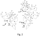
Fig. 2 depicts three perspective views ofrail 1 at viewing directions that are rotated by angular increments of 90 degree around the direction of unit vector (001). Each of the first, second, third, fourth, fifth, sixth, seventh, eighth andninth wall segments -
Fig. 3 is a perspective view of another embodiment ofrail 1 comprising a first, second, third, fourth and fifth bar B1, B2, B3, B4, B5. The first bar B1 and the fifth bar B5 are arranged on free edges of the fourth andsixth wall segments fourth wall segment 14 in a direction opposite to unit vector (010). The fifth bar B5 projects from thesixth wall segment 16 in the direction of unit vector (010). The second and third bars B2, B3 are arranged on themajor surface 8F of theeighth wall segment 18 and project in a direction opposite to unit vector (010). The second and third bars B2, B3 are configured to form a groove. -
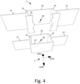
Fig. 4 is a perspective view of abasic bracket 2 comprising a first, second, third, fourth, fifth andsixth crosspiece crosspieces crosspieces crosspieces crosspieces crosspieces crosspieces Crosspieces Crosspiece 25 is equipped with a through-hole 28. -
Fig. 5 is a perspective view of another embodiment of thebracket 2, comprising a first groove G1, a second groove G2 and a tongue T1. Tongue T1 is configured as an extension ofcrosspiece 25 and protrudes fromwall 24 in the direction of unit vector (010).Fig. 5 also depicts a cross-section 2' ofbracket 2 in a plane spanned by unit vectors (100) and (010). As explained above, thecrosspieces -
Fig. 6 shows another perspective view of thebracket 2 ofFig. 5 . Relative to the direction of unit vector (001) thebracket 2 is bound by an upper and lower plane having a normal vectorn = cos α (001) - sin α (100) wherein angle α is from 20 to 40 degree (20° ≤ α ≤ 40°). Accordingly, said upper and lower bounding planes of thebracket 2 are inclined by 20 to 40 degree relative to a plane spanned by unit vectors (100) and (010). In the present application the term "length" ofbracket 2 refers to the extent of a cross-section ofbracket 2 in a plane spanned by unit vectors (010) and (001) in the direction of unit vector (001) and is designated by reference sign L2 depicted inFig. 6 . -
Fig. 7 is a perspective view of another inventive embodiment ofbracket 2 comprising fivecrosspieces Crosspieces crosspieces crosspiece 25. A through-hole 28 is arranged in the interposedcrosspiece 25. Each of the two flankingcrosspieces slots -
Fig. 8 depicts another inventive embodiment ofbracket 2 comprising fivecrosspieces Crosspieces crosspieces crosspiece 25. A through-hole 28 is arranged in the interposedcrosspiece 25. Each of the two flankingcrosspieces cross piece -
Fig. 9 is a perspective view of thebracket 2 engaged with therail 1 and depicts the entanglement of first, second and third tongues T1, T2, T3 with the first, second and third grooves G1, G2, G3, respectively. The through-hole 28 is arranged on theholder 2 in such a way that a central alignment with the slot S1 is ensured. -
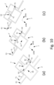
Fig. 10(a), 10(b), 10(c) illustrate the engagement of the bracket with the rail using respective cross-sections 2' and 1'. Initially, as depicted inFig. 10(a) the bracket 2' and rail 1' are separated and bracket 2' is moved in the direction ofarrow 60 substantially opposite to unit vector (100) until bracket 2' abuts rail 1' as shown inFig. 10(b) . Subsequently bracket 2' is sled along the contacting surfaces of rail 1' in the direction ofarrow 61 substantially parallel to unit vector (010) until the first, second and third tongues T1, T2, T3 are entangled with the first, second and third grooves G1, G2, G3, as depicted inFig. 10(c) . -
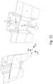
Fig. 11 illustrates the non-positive fastening of thebracket 2 on therail 1 using thefirst screw 3. As indicated by the dashed line, thefirst screw 3 is inserted into through-hole 28 arranged incrosspiece 25 of thebracket 2. Through-hole 28 and thefirst screw 3 are adapted for sliding or screwing insertion of thefirst screw 3. The tip and thread of thefirst screw 3 subsequently penetrate slot S1 of therail 1. The slot S1 and thefirst screw 3 are adapted for non-positive screwing-in of thefirst screw 3 into slot S1. Thefirst screw 3 and the slot S1 are further configured in such a way that the head of thescrew 3 can force-fit thebracket 2 against the therail 1. As depicted inFig. 11 the oblique shape ofbracket 2 affords unhindered access to through-hole 28 along the dashed line substantially parallel to unit vector (100). The oblique shape of thebracket 2 thus facilitates the assembly process. -
Figures 12(a) and 12(b) illustrate the installation of acladding panel 5 using the inventive fastening system. In the depicted embodiment thecladding panel 5 is equipped withoblique suspension slots 51. Eachoblique suspension slot 51 is adapted for suspension on abracket 2.Fig. 12(a) shows an initial situation where thecladding panel 5 is distanced from thebracket 2 mounted on arail 1, the latter being fastened to a building facade (not shown). Thecladding panel 5 is moved in the direction ofarrow 63 substantially opposite to unit vector (100) untilcrosspiece 23 ofbracket 2 is inserted intooblique suspension slot 51. Subsequently,cladding panel 5 is lowered in the direction ofarrow 64 substantially opposite to unit vector (001) until an upper edge ofoblique suspension slot 51 rests on an upper edge ofcrosspiece 23. -
Fig. 13 is a perspective view of therail 1 and aholder 4 for fastening therail 1 to abuilding wall 80.Holder 4 comprises aclamp 41 that is adapted as receptacle forrail 1.Clamp 41 has twolegs legs rail 1 in a form-fitting manner. One or bothlegs hole third screw third screws rail 1 to theclamp 41. Preferably, a tip and thread of the second andthird screws rail 1, particularly the second andeighth wall segments rail 1 takes place during assembly by screwing the second andthird screws holes holder 4 further comprises afourth screw 48 and an optional dowel (not shown) for attachment in ahole 81 in buildingwall 80. -
Fig. 14 is a perspective view of therail 1 fastened to clamp 41 by the second andthird screw Clamp 41 is non-positively attached to abuilding wall 80 by means of thefourth screw 48 and a therefor suited dowel (not shown). -
Fig. 15 depicts a first and second embodiment of acladding panel 5 having a hangingslot 51 and a hangingbolt 52, respectively. -
Fig. 16(a), 16(b) and 16(c) are partial perspective views ofcladding panels 5 equipped with hangingslots slots -
- 1
- rail;
- 1'
- cross-section of
rail 1; - L1
- length of
rail 1; - B1first
- bar of
rail 1; - B2
- second bar of
rail 1; - B3
- third bar of
rail 1; - B4
- fourth bar of
rail 1; - B5
- fifth bar of
rail 1; - S1
- slot of
rail 1; - 11
- first wall segment of
rail 1; - 12
- second wall segment of
rail 1; - 13
- third wall segment of
rail 1; - 14
- fourth wall segment of
rail 1; - 15
- fifth wall segment of
rail 1; - 16
- sixth wall segment of
rail 1; - 17
- seventh wall segment of
rail 1; - 18
- eighth wall segment of
rail 1; - 19
- ninth wall segment of
rail 1; - 1F
- first major surface of
first wall segment 11; - 1B
- second major surface of
first wall segment 11; - 2F
- first major surface of
second wall segment 12; - 2B
- second major surface of
second wall segment 12; - 3F
- first major surface of
third wall segment 13; - 3B
- second major surface of
third wall segment 13; - 4F
- first major surface of
fourth wall segment 14; - 4B
- second major surface of
fourth wall segment 14; - 5F
- first major surface of
fifth wall segment 15; - 5B
- second major surface of
fifth wall segment 15; - 6F
- first major surface of
sixth wall segment 16; - 6B
- second major surface of
sixth wall segment 16; - 7F
- first major surface of
seventh wall segment 17; - 7B
- second major surface of
seventh wall segment 17; - 8F
- first major surface of
eighth wall segment 18; - 8B
- second major surface of
eighth wall segment 18; - 9F
- first major surface of
ninth wall segment 19; - 9B
- second major surface of
ninth wall segment 19; - 2
- bracket;
- 2'
- cross-section of
bracket 2; - L2
- length of
bracket 2; - α
- oblique cut angle of
bracket 2; - T1
- first tongue arranged on
rail 1 or onbracket 2; - G1
- first groove arranged on
rail 1 or onbracket 2; - T2
- second tongue arranged on
rail 1 or onbracket 2; - G2
- second groove arranged on
rail 1 or onbracket 2; - T3
- third tongue arranged on
rail 1 or onbracket 2; - G3
- third groove arranged on
rail 1 or onbracket 2; - 21
- first crosspiece of
bracket 2; - 22
- second crosspiece of
bracket 2; - 23
- third crosspiece of
bracket 2; - 24
- fourth crosspiece of
bracket 2; - 25
- fifth crosspiece of
bracket 2; - 27
- sixth crosspiece of
bracket 2; - 28
- through-hole arranged in
crosspiece 25 of bracket; - S22
- slot arranged in
crosspiece 22 for engagement with hanging bolt ofcladding panel 5; - S24
- slot arranged in
crosspiece 24 for engagement with hanging bolt ofcladding panel 5; - C22
- bolt attached to crosspiece 22 for engagement with hanging slot of
cladding panel 5; - C24
- bolt attached to crosspiece 24 for engagement with hanging slot of
cladding panel 5; - 3
- first screw adapted for sliding or screwing insertion into through-
hole 28 and non-positive screwing-in into slot S1 in order to fastenbracket 2 torail 1; - 4
- holder for
fastening rail 1 to a building facade; - 41
- clamp of
holder 4 adapted as receptacle forrail 1; - 42
- first leg of
clamp 41; - 43
- second leg of
clamp 41; - 44
- through-hole in
first leg 42; - 45
- through-hole in
second leg 43; - 46
- second screw for
fastening rail 1 to clamp 41; - 47
- third screw for
fastening rail 1 to clamp 41; - 48
- fourth screw for
fastening clamp 41 to buildingwall 80; - 5
- cladding panel to be fastened to
rail 1; - 51
- oblique suspension or hanging slot of
cladding panel 5; - 52
- hanging bolt of
cladding panel 5; - 60
- first motion arrow indicating first translation of
bracket 2 relative to rail 1; - 61
- second motion arrow indicating second translation of
bracket 2 relative to rail 1; - 63
- third motion arrow indicating translation of
cladding panel 5 relative tobracket 2 andrail 1; - 64
- fourth motion arrow indicating translation of
cladding panel 5 relative tobracket 2 andrail 1; - 7
- orthonormal coordinate system with unit vectors (100), (010) and (001);
- 80
- building wall;
- 81
- hole in building
wall 80 adapted for third srew 46 and dowel; - n
- unit vector with
n = cos α (001) - sin α (100) in a direction perpendicular to the oblique cut plane ofbracket 2;
Claims (12)
- System for fastening cladding panels (5) to a building facade, comprising a rail (1), a bracket (2) and a first screw (3) for fixing the bracket (2) to the rail (1), characterized in thatthe rail (1) comprises at least one first tongue (T1) and the bracket (2) comprises at least one first groove (G1);
orthe rail (1) comprises at least one first groove (G1) and the bracket (2) comprises at least one first tongue (T1);
andthe first tongue and the first groove are configured for sliding engagement. - The system of claim 1, characterized in thatthe rail (1) comprises a second tongue (T2) and the bracket (2) comprises a second groove (G2);
orthe rail (1) comprises a second groove (G2) and the bracket (2) comprises a second tongue (T2);
andthe second tongue (T2) and the second groove (G2) are configured for sliding engagement. - The system of claim 2, characterized in thatthe rail (1) comprises a third tongue (T3) and the bracket (2) comprises a third groove (G3);
orthe rail (1) comprises a third groove (G3) and the bracket (2) comprises a third tongue (T3);
andthe third tongue (T3) and the third groove (G3) are configured for sliding engagement. - The system of claim 1, 2 or 3, characterized in that the rail (1) and the bracket (2) are configured for releasable engagement.
- The system of any one of claims 1 to 4, characterized in that the bracket (2) comprises a through-hole (28) for sliding or screwing insertion of the first screw (3).
- The system of any one of claims 1 to 5, characterized in that the rail (1) comprises a slot (S1) adapted for non-positive screwing-in of the first screw (3).
- The system of any one of claims 1 to 6, characterized in that the rail (1) comprises 5 to 15 wall segments (11, 12, 13, 14, 15, 16, 17, 18, 19), a first group of wall segments (11, 13, 15, 17, 19) are arranged substantially perpendicular to a second group of wall segments (12, 14, 16, 18), each wall segment (11, 13, 15, 17, 19) of the first group is connected to one or two wall segments (12, 14, 16, 18) of the seond group and each wall segment (12, 14, 16, 18) of the second group is connected to two or three wall segments (11, 13, 15, 17, 19) of the first group.
- The system of any one of claims 1 to 7, characterized in that the rail (1) has a length of 1000 to 10000 mm.
- The system of any one of claims 1 to 8, characterized in that the rail (1) has a cross-section with an area of 370 to 560 mm2.
- The system of any one of claims 1 to 9, characterized in that the bracket (2) comprises 5 to 10 crosspieces (21, 22, 23, 24, 25, 27), a first group of crosspieces (21, 23, 25, 27) are arranged substantially perpendicular to a second group of crosspieces (22, 24), each crosspiece (21, 23, 25, 27) of the first group is connected to one or two crosspieces (22, 24) of the second group and each crosspiece (22, 24) of the second group is connected to two or three crosspieces (21, 23, 25, 27) of the first group.
- The system of any one of claims 1 to 10, characterized in that the bracket (2) has a length of 20 to 50 mm.
- The system of any one of claims 1 to 11, characterized in that the bracket (2) has a cross-section with an area of 340 to 510 mm2.
Priority Applications (1)
| Application Number | Priority Date | Filing Date | Title |
|---|---|---|---|
| EP23208154.7A EP4553247A1 (en) | 2023-11-07 | 2023-11-07 | System for fastening cladding panels to a building façade |
Applications Claiming Priority (1)
| Application Number | Priority Date | Filing Date | Title |
|---|---|---|---|
| EP23208154.7A EP4553247A1 (en) | 2023-11-07 | 2023-11-07 | System for fastening cladding panels to a building façade |
Publications (1)
| Publication Number | Publication Date |
|---|---|
| EP4553247A1 true EP4553247A1 (en) | 2025-05-14 |
Family
ID=88731365
Family Applications (1)
| Application Number | Title | Priority Date | Filing Date |
|---|---|---|---|
| EP23208154.7A Pending EP4553247A1 (en) | 2023-11-07 | 2023-11-07 | System for fastening cladding panels to a building façade |
Country Status (1)
| Country | Link |
|---|---|
| EP (1) | EP4553247A1 (en) |
Citations (5)
| Publication number | Priority date | Publication date | Assignee | Title |
|---|---|---|---|---|
| WO2020084143A1 (en) | 2018-10-25 | 2020-04-30 | 3A Composites Gmbh | Cladding system for a wall, arrangement of the cladding system and method for mounting the cladding system |
| EP3540145B1 (en) | 2018-03-16 | 2020-09-30 | 3A Composites GmbH | Cladding element and system for a wall |
| IT201900007260A1 (en) * | 2019-05-27 | 2020-11-27 | Atena Spa | ATTACHMENT ASSEMBLY FOR VENTILATED WALLS |
| DE102021103756A1 (en) * | 2020-03-06 | 2021-09-09 | Slavonia Baubedarf Gmbh | Adapter for holding facade elements |
| WO2023041821A1 (en) * | 2021-09-17 | 2023-03-23 | Sistemas Tecnicos Del Accesorio Y Componentes, S.L. | Device for a ventilated facade |
-
2023
- 2023-11-07 EP EP23208154.7A patent/EP4553247A1/en active Pending
Patent Citations (5)
| Publication number | Priority date | Publication date | Assignee | Title |
|---|---|---|---|---|
| EP3540145B1 (en) | 2018-03-16 | 2020-09-30 | 3A Composites GmbH | Cladding element and system for a wall |
| WO2020084143A1 (en) | 2018-10-25 | 2020-04-30 | 3A Composites Gmbh | Cladding system for a wall, arrangement of the cladding system and method for mounting the cladding system |
| IT201900007260A1 (en) * | 2019-05-27 | 2020-11-27 | Atena Spa | ATTACHMENT ASSEMBLY FOR VENTILATED WALLS |
| DE102021103756A1 (en) * | 2020-03-06 | 2021-09-09 | Slavonia Baubedarf Gmbh | Adapter for holding facade elements |
| WO2023041821A1 (en) * | 2021-09-17 | 2023-03-23 | Sistemas Tecnicos Del Accesorio Y Componentes, S.L. | Device for a ventilated facade |
Similar Documents
| Publication | Publication Date | Title |
|---|---|---|
| US6047838A (en) | Modular support post | |
| CA2816951C (en) | Wall assembly | |
| US4689930A (en) | Partition structure | |
| US6920734B2 (en) | Bridging system for off-module studs | |
| US6802171B2 (en) | Framing member with fastener attachments having square threads | |
| US20060156651A1 (en) | Mounting system with threaded sliding block | |
| US20080104922A1 (en) | Connector arrangement for a wall panel system | |
| US20090000235A1 (en) | Architectural connectors for modular framing systems | |
| WO1996033323A1 (en) | Modular office furniture partition | |
| GB2196664A (en) | Wall tie for panels and claddings | |
| CZ250595A3 (en) | Siding | |
| US4570402A (en) | Connector apparatus for modular panel structure | |
| RU2317764C2 (en) | System, clamping member and locking member for connection of profiled members | |
| US4587774A (en) | System adapted to support a cantilevered load at a partition break | |
| PL183012B1 (en) | System for assembling and securing lining elements | |
| WO2024213242A1 (en) | Retaining system for plate-shaped components | |
| CN216475865U (en) | Top keel connecting piece | |
| CH598448A5 (en) | Support structure for wall covering plates | |
| JP2884136B2 (en) | Girder material and receiving device used for receiving device for wiring and piping material installation | |
| GB2436747A (en) | Framing system | |
| US20040146343A1 (en) | Seismic adapter | |
| DE202023102069U1 (en) | Holding system for panel-shaped components | |
| JP3295348B2 (en) | Mounting tools such as pipes, control panels, boxes, cables, etc. that can be attached to the building, beams, haze, etc. | |
| GB2436748A (en) | Framing System | |
| KR920000595B1 (en) | Thermal insulation panel, panel device and fixing method |
Legal Events
| Date | Code | Title | Description |
|---|---|---|---|
| PUAI | Public reference made under article 153(3) epc to a published international application that has entered the european phase |
Free format text: ORIGINAL CODE: 0009012 |
|
| STAA | Information on the status of an ep patent application or granted ep patent |
Free format text: STATUS: THE APPLICATION HAS BEEN PUBLISHED |
|
| AK | Designated contracting states |
Kind code of ref document: A1 Designated state(s): AL AT BE BG CH CY CZ DE DK EE ES FI FR GB GR HR HU IE IS IT LI LT LU LV MC ME MK MT NL NO PL PT RO RS SE SI SK SM TR |
|
| STAA | Information on the status of an ep patent application or granted ep patent |
Free format text: STATUS: REQUEST FOR EXAMINATION WAS MADE |
|
| 17P | Request for examination filed |
Effective date: 20251106 |