EP4553234A1 - Work machine and method for controlling work machine - Google Patents
Work machine and method for controlling work machine Download PDFInfo
- Publication number
- EP4553234A1 EP4553234A1 EP23872176.5A EP23872176A EP4553234A1 EP 4553234 A1 EP4553234 A1 EP 4553234A1 EP 23872176 A EP23872176 A EP 23872176A EP 4553234 A1 EP4553234 A1 EP 4553234A1
- Authority
- EP
- European Patent Office
- Prior art keywords
- work
- restriction
- implement
- work implement
- fault
- Prior art date
- Legal status (The legal status is an assumption and is not a legal conclusion. Google has not performed a legal analysis and makes no representation as to the accuracy of the status listed.)
- Pending
Links
Images




Classifications
-
- E—FIXED CONSTRUCTIONS
- E02—HYDRAULIC ENGINEERING; FOUNDATIONS; SOIL SHIFTING
- E02F—DREDGING; SOIL-SHIFTING
- E02F9/00—Component parts of dredgers or soil-shifting machines, not restricted to one of the kinds covered by groups E02F3/00 - E02F7/00
- E02F9/20—Drives; Control devices
- E02F9/2025—Particular purposes of control systems not otherwise provided for
- E02F9/2033—Limiting the movement of frames or implements, e.g. to avoid collision between implements and the cabin
-
- E—FIXED CONSTRUCTIONS
- E02—HYDRAULIC ENGINEERING; FOUNDATIONS; SOIL SHIFTING
- E02F—DREDGING; SOIL-SHIFTING
- E02F9/00—Component parts of dredgers or soil-shifting machines, not restricted to one of the kinds covered by groups E02F3/00 - E02F7/00
- E02F9/24—Safety devices, e.g. for preventing overload
-
- E—FIXED CONSTRUCTIONS
- E02—HYDRAULIC ENGINEERING; FOUNDATIONS; SOIL SHIFTING
- E02F—DREDGING; SOIL-SHIFTING
- E02F3/00—Dredgers; Soil-shifting machines
- E02F3/04—Dredgers; Soil-shifting machines mechanically-driven
- E02F3/28—Dredgers; Soil-shifting machines mechanically-driven with digging tools mounted on a dipper- or bucket-arm, i.e. there is either one arm or a pair of arms, e.g. dippers, buckets
- E02F3/36—Component parts
- E02F3/42—Drives for dippers, buckets, dipper-arms or bucket-arms
- E02F3/43—Control of dipper or bucket position; Control of sequence of drive operations
- E02F3/431—Control of dipper or bucket position; Control of sequence of drive operations for bucket-arms, front-end loaders, dumpers or the like
- E02F3/432—Control of dipper or bucket position; Control of sequence of drive operations for bucket-arms, front-end loaders, dumpers or the like for keeping the bucket in a predetermined position or attitude
-
- E—FIXED CONSTRUCTIONS
- E02—HYDRAULIC ENGINEERING; FOUNDATIONS; SOIL SHIFTING
- E02F—DREDGING; SOIL-SHIFTING
- E02F9/00—Component parts of dredgers or soil-shifting machines, not restricted to one of the kinds covered by groups E02F3/00 - E02F7/00
- E02F9/20—Drives; Control devices
- E02F9/2058—Electric or electro-mechanical or mechanical control devices of vehicle sub-units
- E02F9/2083—Control of vehicle braking systems
-
- E—FIXED CONSTRUCTIONS
- E02—HYDRAULIC ENGINEERING; FOUNDATIONS; SOIL SHIFTING
- E02F—DREDGING; SOIL-SHIFTING
- E02F9/00—Component parts of dredgers or soil-shifting machines, not restricted to one of the kinds covered by groups E02F3/00 - E02F7/00
- E02F9/20—Drives; Control devices
- E02F9/22—Hydraulic or pneumatic drives
- E02F9/2221—Control of flow rate; Load sensing arrangements
- E02F9/2225—Control of flow rate; Load sensing arrangements using pressure-compensating valves
- E02F9/2228—Control of flow rate; Load sensing arrangements using pressure-compensating valves including an electronic controller
-
- E—FIXED CONSTRUCTIONS
- E02—HYDRAULIC ENGINEERING; FOUNDATIONS; SOIL SHIFTING
- E02F—DREDGING; SOIL-SHIFTING
- E02F9/00—Component parts of dredgers or soil-shifting machines, not restricted to one of the kinds covered by groups E02F3/00 - E02F7/00
- E02F9/20—Drives; Control devices
- E02F9/22—Hydraulic or pneumatic drives
- E02F9/226—Safety arrangements, e.g. hydraulic driven fans, preventing cavitation, leakage, overheating
-
- E—FIXED CONSTRUCTIONS
- E02—HYDRAULIC ENGINEERING; FOUNDATIONS; SOIL SHIFTING
- E02F—DREDGING; SOIL-SHIFTING
- E02F9/00—Component parts of dredgers or soil-shifting machines, not restricted to one of the kinds covered by groups E02F3/00 - E02F7/00
- E02F9/20—Drives; Control devices
- E02F9/22—Hydraulic or pneumatic drives
- E02F9/2264—Arrangements or adaptations of elements for hydraulic drives
- E02F9/2267—Valves or distributors
-
- E—FIXED CONSTRUCTIONS
- E02—HYDRAULIC ENGINEERING; FOUNDATIONS; SOIL SHIFTING
- E02F—DREDGING; SOIL-SHIFTING
- E02F9/00—Component parts of dredgers or soil-shifting machines, not restricted to one of the kinds covered by groups E02F3/00 - E02F7/00
- E02F9/20—Drives; Control devices
- E02F9/22—Hydraulic or pneumatic drives
- E02F9/2278—Hydraulic circuits
- E02F9/2285—Pilot-operated systems
-
- E—FIXED CONSTRUCTIONS
- E02—HYDRAULIC ENGINEERING; FOUNDATIONS; SOIL SHIFTING
- E02F—DREDGING; SOIL-SHIFTING
- E02F9/00—Component parts of dredgers or soil-shifting machines, not restricted to one of the kinds covered by groups E02F3/00 - E02F7/00
- E02F9/26—Indicating devices
- E02F9/267—Diagnosing or detecting failure of vehicles
- E02F9/268—Diagnosing or detecting failure of vehicles with failure correction follow-up actions
-
- E—FIXED CONSTRUCTIONS
- E02—HYDRAULIC ENGINEERING; FOUNDATIONS; SOIL SHIFTING
- E02F—DREDGING; SOIL-SHIFTING
- E02F3/00—Dredgers; Soil-shifting machines
- E02F3/04—Dredgers; Soil-shifting machines mechanically-driven
- E02F3/28—Dredgers; Soil-shifting machines mechanically-driven with digging tools mounted on a dipper- or bucket-arm, i.e. there is either one arm or a pair of arms, e.g. dippers, buckets
- E02F3/36—Component parts
- E02F3/42—Drives for dippers, buckets, dipper-arms or bucket-arms
- E02F3/43—Control of dipper or bucket position; Control of sequence of drive operations
- E02F3/431—Control of dipper or bucket position; Control of sequence of drive operations for bucket-arms, front-end loaders, dumpers or the like
Definitions
- the present invention relates to a work machine and a control method for a work machine.
- Patent Document 1 discloses a work machine that can still travel to a location that does not obstruct traffic or to a destination such as a repair shop, even in the event of a fault.
- Patent Document 1 WO2015/111549
- the present disclosure aims to provide a work machine and a control method for a work machine that can prevent the continuation of work when a fault occurs and that can prompt a user to deal with the fault.
- a work machine includes a traveling unit, a work implement, a parking brake, and a controller.
- the work implement is mounted to the traveling unit.
- the controller detects a fault that allows the work machine to remain operable, in a state where the parking brake is released, the controller is configured to restrict operation of the work implement.
- a work machine and a control method for a work machine are provided that can prevent the continuation of the ongoing work when a fault occurs and that can prompt a user to deal with the fault.
- FIG. 1 is a schematic diagram illustrating the configuration of a wheel loader 1 (an example of a work machine) according to the present embodiment.
- the wheel loader 1 according to the present embodiment includes a traveling unit 2, a work implement 3, and a control system 20 (see FIG. 2 ).
- the work implement 3 is mounted to the traveling unit 2.
- the traveling unit 2 includes a vehicular body frame 10, a pair of front tires 4, a cab 5, an engine room 6, a pair of rear tires 7, and a steering cylinder 9.
- the wheel loader 1 performs work such as loading earth and sand using the work implement 3.
- the vehicular body frame 10 is of a so-called articulated type, and has a front frame 11, a rear frame 12, and a connecting shaft portion 13.
- the front frame 11 is disposed in front of the rear frame 12.
- the connecting shaft portion 13 is centered in the vehicle-width direction to connect the front frame 11 and the rear frame 12 so that both of them are swingable.
- the pair of front tires 4 is attached to the left and right of the front frame 11, respectively.
- the pair of rear tires 7 is attached to the left and right of the rear frame 12, respectively.
- the work implement 3 is driven by hydraulic oil from a work implement pump 31 (see FIG. 3 which will be described below).
- the work implement 3 includes a boom 14, a bucket 15, a boom cylinder 16 (an example of hydraulic actuator), a bucket cylinder 17 (an example of hydraulic actuator), and a bell crank 18.
- the boom 14 is attached to the front frame 11.
- the bucket 15 is attached to the tip of the boom 14.
- the boom cylinder 16 and the bucket cylinder 17 are hydraulic cylinders. One end of the boom cylinder 16 is attached to the front frame 11, and the other end of the boom cylinder 16 is attached to the boom 14. The boom cylinder 16 extends and contracts, causing the boom 14 to swing up and down. One end of the bucket cylinder 17 is attached to the front frame 11, and the other end of the bucket cylinder 17 is attached to the bucket 15 via the bell crank 18. The bucket cylinder 17 expands and contracts, causing the bucket 15 to swing up and down.
- the cab 5 is mounted on the rear frame 12. Inside the cab 5, for example, a steering wheel 19 (see FIG. 3 which will be described below) for steering operations, a lever for operating the work implement 3, and various display devices are arranged.
- the engine room 6 is mounted on the rear frame 12 behind the cab 5 and houses an engine.
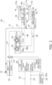
- FIG. 2 is a diagram illustrating the control system 20 in the wheel loader 1.
- the control system 20 further includes a work implement drive circuit 21, a work-implement lock switch 22 (an example of a restriction-operating section), a work-implement lock valve 23 (an example of a restricting valve), a parking brake switch 24, a parking brake 25, and an HST controller 26 (an example of a controller).
- a work implement drive circuit 21 a work-implement lock switch 22 (an example of a restriction-operating section), a work-implement lock valve 23 (an example of a restricting valve), a parking brake switch 24, a parking brake 25, and an HST controller 26 (an example of a controller).
- the work implement drive circuit 21 includes a work implement pump 31, a boom valve 32 (an example of a work-implement valve), a bucket valve 33 (an example of a work-implement valve), a boom lever 34, a bucket lever 35, a self-depressurizing valve 36, a pair of boom pilot valves 37a, 37b (an example of a pilot valve), a pair of bucket pilot valves 38a, 38b (an example of a pilot valve), and a first pipe 41 to an eleventh pipe 51.
- the work implement pump 31 supplies hydraulic oil to the boom cylinder 16 via the boom valve 32.
- the work implement pump 31 supplies hydraulic oil to the bucket cylinder 17 via the bucket valve 33.
- the boom cylinder 16 has a cylinder chamber including an extension chamber 16a and a contraction chamber 16b which are separated by a piston.
- the boom cylinder 16 extends when hydraulic oil is supplied to the extension chamber 16a and the hydraulic oil is discharged from the contraction chamber 16b.
- the boom cylinder 16 contracts when hydraulic oil is supplied to the contraction chamber 16b and the hydraulic oil is discharged from the extension chamber 16a.
- the boom valve 32 is a directional control valve.
- the boom valve 32 and the work implement pump 31 are connected by the first pipe 41.
- the boom valve 32 and the extension chamber 16a are connected by the second pipe 42.
- the boom valve 32 and the contraction chamber 16b are connected by the third pipe 43.
- the boom valve 32 has a sleeve and a spool that is movable relative to the sleeve.
- the spool is movable to four positions relative to the sleeve.
- the boom valve 32 connects the first pipe 41 to the second pipe 42 and connects the third pipe 43 to a drain pipe (not shown).
- the hydraulic oil supplied from the work implement pump 31 is supplied to the extension chamber 16a, and the hydraulic oil is discharged from the contraction chamber 16b.
- the boom valve 32 connects the first pipe 41 to the third pipe 43 and connects the second pipe 42 to the drain pipe.
- the hydraulic oil supplied from the work implement pump 31 is supplied to the contraction chamber 16b, and the hydraulic oil is discharged from the extension chamber 16a.
- the boom valve 32 does not connect the first pipe 41, the second pipe 42, the third pipe 43, and the drain pipe to each other, and the supply and discharge of the hydraulic oil is stopped.
- the boom valve 32 connects the first pipe 41 and the second pipe 42 to the drain pipe, and the third pipe 43 is not connected to any pipe.
- the bucket cylinder 17 has a cylinder chamber including an extension chamber 17a and a contraction chamber 17b which are separated by a piston.
- a piston When hydraulic oil is supplied to the extension chamber 17a and the hydraulic oil is discharged from the contraction chamber 17b, the bucket cylinder 17 extends, and the bucket 15 performs a tilt motion.
- the bucket cylinder 17 contracts and the bucket 15 performs a dump motion.
- the bucket valve 33 is a directional control valve.
- the fourth pipe 44 branched from the first pipe 41 is connected to the bucket valve 33.
- the bucket valve 33 and the work implement pump 31 are connected by the first pipe 41 and the fourth pipe 44.
- the bucket valve 33 and the extension chamber 17a are connected by the fifth pipe 45.
- the bucket valve 33 and the contraction chamber 17b are connected by the sixth pipe 46.
- the bucket valve 33 has a sleeve and a spool that is movable relative to the sleeve.
- the spool is movable to three positions relative to the sleeve.
- the bucket valve 33 connects the fourth pipe 44 to the fifth pipe 45 and connects the sixth pipe 46 to a drain pipe (not shown).
- the hydraulic oil supplied from the work implement pump 31 is supplied to the extension chamber 17a, and the hydraulic oil is discharged from the contraction chamber 17b.
- the bucket valve 33 connects the fourth pipe 44 to the sixth pipe 46 and the fifth pipe 45 to the drain pipe.
- the hydraulic oil supplied from the work implement pump 31 is supplied to the contraction chamber 17b, and the hydraulic oil is discharged from the extension chamber 17a.
- the bucket valve 33 does not connect the fourth pipe 44, the fifth pipe 45, the sixth pipe 46, and the drain pipe to each other, and the supply and discharge of the hydraulic oil is stopped.
- the boom lever 34 is arranged in the cab 5.
- the boom lever 34 controls the opening of the boom valve 32.
- the spool moves relative to the sleeve in response to the operation of the boom lever 34, so that the hydraulic oil supplied to the boom cylinder 16 is adjusted.
- the bucket lever 35 is arranged in the cab 5.
- the bucket lever 35 controls the opening of the bucket valve 33.
- the spool moves relative to the sleeve in response to the operation of the bucket lever 35, so that the hydraulic oil supplied to the bucket cylinder 17 is adjusted.
- the self-depressurizing valve 36 reduces the pressure of the hydraulic oil discharged from the work implement pump 31.
- the hydraulic oil reduced in pressure is used as pilot hydraulic oil.
- the self-depressurizing valve 36 is arranged in a seventh pipe 47 that connects the first pipe 41 with the pair of boom pilot valves 37a, 37b and the bucket pilot valves 38a, 38b.
- the pair of boom pilot valves 37a, 37b is connected to the boom lever 34, and their openings are adjusted by the manipulation of the boom lever 34.
- the hydraulic oil reduced in pressure by the self-depressurizing valve 36 is supplied to the pair of boom pilot valves 37a, 37b.
- One of the pair of boom pilot valves 37a, 37b, that is the boom pilot valve 37a is connected to the first pilot chamber 32a of the boom valve 32 via the eighth pipe 48.
- the other boom pilot valve 37b is connected to the second pilot chamber 32b of the boom valve 32 via the ninth pipe 49.
- the amount of hydraulic oil supplied from the boom pilot valves 37a, 37b is adjusted by manipulation of the boom lever 34, so that the amount of hydraulic oil supplied to the first pilot chamber 32a and the second pilot chamber 32b is adjusted.
- the spool in the boom valve 32 moves relative to the sleeve, and the amount of hydraulic oil supplied to the boom cylinder 16 is adjusted.
- the boom lever 34 is tilted to the left in Figure
- the amount of hydraulic oil supplied from the boom pilot valve 37b increases, and thereby, the spool of the boom valve 32 moves to the first position P1. This movement causes the boom cylinder 16 to extend, which moves the boom 14 upward.
- the pair of bucket pilot valves 38a, 38b is connected to the bucket lever 35, and their opening degrees are adjusted by manipulation the bucket lever 35.
- the hydraulic oil decreased in pressure by the self-depressurizing valve 36 is supplied to the pair of bucket pilot valves 38a, 38b.
- One of the pair of bucket pilot valves 38a, 38b, that is the bucket pilot valve 38a is connected to the first pilot chamber 33a of the bucket valve 33 via the tenth pipe 50.
- the other bucket pilot valve 38b is connected to the second pilot chamber 33b of the bucket valve 33 via the eleventh pipe 51.
- the amount of hydraulic oil supplied from the bucket pilot valve 38a and the bucket pilot valve 38b is adjusted by manipulation of the bucket lever 35, and thereby, the amount of hydraulic oil supplied to the first pilot chamber 33a and the second pilot chamber 33b is adjusted.
- the spool in the bucket valve 33 moves relative to the sleeve, and the amount of hydraulic oil supplied to the bucket cylinder 17 is adjusted.
- the amount of hydraulic oil supplied from the bucket pilot valve 38b increases, so that the spool of the bucket valve 33 moves to the second position Q2. This causes the bucket cylinder 17 to contract, and the bucket 15 performs a dump operation.
- the work-implement lock switch 22 is a switch for restricting (hereinafter, also referred to as locking) or releasing the restriction (hereinafter, also referred to as releasing the lock) of the operation of the work implement 3.
- the work-implement lock switch 22 is operated by an operator.
- the work-implement lock switch 22 is located in the cab 5.
- FIG. 3 is a diagram illustrating the steering wheel 19 and the vicinity of the steering wheel 19 in the cab 5. As illustrated in FIG. 3 , in the present embodiment, the work-implement lock switch 22 is located on the right side of the driver's seat.
- the work-implement lock switch 22 is operated to an on-state or an off-state by the operator.
- a signal corresponding to the operation is input to the HST controller 26.
- the work-implement lock valve 23 is positioned in the seventh pipe 47.
- the work-implement lock valve 23 is arranged downstream of the self-depressurizing valve 36.
- the work-implement lock valve 23 is an electromagnetic valve and is driven by a signal from the HST controller 26.
- the work-implement lock valve 23 is switchable between a locked state in which the supply of hydraulic oil to the pilot valves 37a, 37b, 38a, and 38b through the seventh pipe 47 is stopped and an unlocked state in which the supply of hydraulic oil is enabled.
- the HST controller 26 stops outputting a signal to the work-implement lock valve 23, which switches the work-implement lock valve 23 into the locked state.
- the HST controller 26 outputs a signal to the work-implement lock valve 23, which switches the work-implement lock valve 23 into the unlocked state.
- the parking brake switch 24 is a switch for locking and releasing the lock of the parking brake.
- the parking brake switch 24 is operated by an operator. As illustrated in FIG. 3 , the parking brake switch 24 is positioned to the side of the steering wheel 19 inside the cab 5. The parking brake switch 24 is operated to an on-state or an off-state by the operator.
- the parking brake 25 is used to stop the traveling unit 2 and brakes the traveling unit 2.
- the parking brake 25 is mounted, for example, to a transfer (not shown).
- the transfer divides the output from the engine between the front axle to which the front tires 4 are connected and the rear axle to which the rear tires 7 are connected.
- a wet multi-stage brake that is switchable between a braking state and a non-braking state, or a disk brake may be used as the parking brake 25.
- the HST controller 26 includes a processor and a storage device.
- the processor is, for example, a central processing unit (CPU). Alternatively, the processor may be a different processor from the CPU.
- the processor enforces processing for controlling the wheel loader 1 according to a program.
- the storage device includes non-volatile memory such as read only memory (ROM) and volatile memory such as random access memory (RAM).
- the storage device may include an auxiliary storage device such as a hard disk or a solid state drive (SSD).
- SSD solid state drive
- the storage device is an example of a non-transitory processor-readable recording intermediate.
- the storage device stores programs and data for controlling the wheel loader 1.
- the HST controller 26 detects a fault. When the HST controller 26 detects that the fault is an intermediate one (which will be described below), it enforces a functional restriction F.
- the functional restriction F is designed so that the operation of the work implement 3 and the traveling do not occur simultaneously. While the HST controller 26 does not detect an intermediate fault, it operates the work-implement lock valve 23 in response to a signal input from the work-implement lock switch 22 as described above, thereby limiting or releasing the limitation on the operation of the work implement 3.
- FIG. 4 is a table T1 explaining classification of the faults.
- Faults can be divided into minor, intermediate, and major faults.
- a minor fault is, for example, a seat heater fault, and is a fault in which the safety function has not failed and does not affect the continuation of the ongoing work. In the case of a minor fault, there is no problem in carrying out the ongoing work, requiring no need to enforce the functional restriction F.
- a major fault is, for example, a fault in the forward/reverse switch (FNR) lever or a fault in the work implement pump, and is a fault in which the safety function has failed and the machine cannot continue to operate. In the event of a major fault, the ongoing work cannot continue, eliminating the need to execute the functional restriction F.
- An intermediate fault is a state in which the safety function has failed, but the work machine remains operable. An intermediate fault can be described as a state in which the work machine continues to be operable, although there is a risk that safety could be compromised when subsequent fault arises.
- the HST controller 26 when an intermediate fault is detected, the HST controller 26 enforces the functional restriction F. On the other hand, minor and major faults are not subject to the functional restriction F, and no functional restriction F is enforced on them.
- FIG. 5A is a diagram illustrating a control system for operating such an attachment. As illustrated in FIG. 5A , an attachment cylinder 61 is additionally mounted to the control system 20 of FIG. 2 in order to drive the attachment. In addition, an attachment valve 62 is provided to adjust the flow rate of hydraulic oil supplied to the attachment cylinder 61.
- Two EPC valves 63a and 63b are provided to supply pilot hydraulic oil to a first pilot chamber 62a and a second pilot chamber 62b of the attachment valve 62.
- a signal from an electric lever 64 for operating the attachment is input to the HST controller 26, and then the HST controller 26 controls the EPC valves 63a, 63b according to the degree of manipulation of the lever.
- the attachment valve 62 adjusts the flow rate of hydraulic oil supplied from the work implement pump 31 to the attachment cylinder 61, causing the attachment cylinder 61 to expand and contract, and the attachment operates accordingly.
- the electric lever 64 for operating the attachment outputs an attachment operation signal (hereinafter, referred to as a signal s1) and a fault diagnosis signal (hereinafter, signal s2) to the HST controller 26.
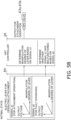
- FIG. 5B illustrates the signals s1 and s2 in the normal state.
- the signals s1 and s2 each indicate the value of the output voltage for the degree of manipulation of the electric lever 64 for operating an attachment.
- the output voltages of the signals s1 and s2 are set to be larger as the degree of manipulation of the lever increases.
- the signals s1 and s2 output the same value.
- the HST controller 26 determines the degree of manipulation of the lever from the signal s1 and outputs an output for operating the attachment to the EPC valves 63a and 63b.
- the HST controller 26 compares the signals s1 and s2, and when the values of the signals s1 and s2 are the same, it determines that no fault has occurred.
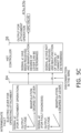
- the lever manipulation degree can be determined from the input signal s1. However, no determination on a fault can be made because the signal s2 is not input.
- an intermediate fault can be defined as a state in which the safety function has failed, but the work machine is still able to operate.
- An intermediate fault includes cases where one of the redundant configurations for the safety function fails.
- an intermediate fault may include, for example, a power fault on the output side of the HST controller 26.
- the functional restriction F enforced by the HST controller 26 (an example of a controller) upon detection of an intermediate fault will be described.
- the functional restriction F When the functional restriction F is executed, it ensures a setting where the operation of the work implement 3 and the traveling cannot occur simultaneously.
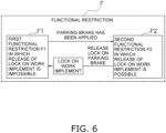
- FIG. 6 is a diagram illustrating a state transition of the controls in the functional restriction F.
- the functional restriction F includes a first functional restriction F1 that allows the traveling while restricting the operation of the work implement 3, and a second functional restriction F2 that allows the operation of the work implement 3 while restricting the traveling.
- the HST controller 26 executes the first functional restriction F1 by disenabling the releasing the lock of the work implement 3 in the case where the parking brake 25 is not applied.
- the HST controller 26 does not drive the work-implement lock valve 23 and does not release the lock of the work implement 3, even when the work-implement lock switch 22 is operated and a signal to release the lock is input to the HST controller 26 from the work-implement lock switch 22.
- the HST controller 26 executes the second functional restriction F2 by allowing the work implement 3 to be unlocked in the case where the parking brake 25 is applied.
- the HST controller 26 drives the work-implement lock valve 23 to release the lock of the work implement 3 when the work-implement lock switch 22 is operated and a signal for an unlock is input to the HST controller 26 from the work-implement lock switch 22.
- the HST controller 26 transitions to the second functional restriction F2 upon detection of the state where the parking brake 25 is applied.
- the HST controller 26 drives the work-implement lock valve 23 to put the work implement 3 into the locked state and transitions from the second functional restriction F2 to the first functional restriction F1.
- the first functional restriction F1 and second functional restriction F2 prevent the operator from operating the work implement 3 and traveling simultaneously. As a result, the ongoing work cannot continue, and it is possible to disable the continuous operation of the wheel loader 1 while still allowing the minimum function of traveling to a destination.
- the minimum function includes lifting the work implement 3 from the ground, positioning it for traveling, and traveling the wheel loader 1.
- the HST controller 26 When the HST controller 26 detects an intermediate fault while moving the work implement 3 with the lock of the work implement 3 being released and the parking brake 25 being released, the work implement 3 will be suddenly locked regardless of the operator's intention because the parking brake 25 has been released. In such a case, the balance may be lost due to the inertia of the work implement 3.
- the operator when the HST controller 26 detects an intermediate fault, the operator first operates the work-implement lock switch 22 to lock the work implement 3, and then starts execution of the first functional restriction F1 (see steps S13 and S14 described below).
- FIG. 7 is a flow diagram illustrating a control operation when a fault occurs in the wheel loader 1 of the present embodiment.
- step S11 one example of a fault detection step
- the HST controller 26 determines whether the fault is an intermediate fault or not. When the fault is determined to be a minor fault or a major fault rather than an intermediate one, the control ends.
- the HST controller 26 determines in step S12 whether the parking brake 25 has been applied. Specifically, the HST controller 26 determines whether the parking brake 25 has been applied based on a signal input from the parking brake switch 24.
- step S13 the HST controller 26 determines whether the work implement 3 has been locked. Specifically, the HST controller 26 determines whether the work implement 3 has been locked by driving the work-implement lock valve 23 based on a signal input from the work-implement lock switch 22.
- step S13 When it is determined in step S13 that the work implement 3 has not been locked, the HST controller 26 will wait until the work implement 3 is locked. Once the work implement 3 is locked in step S13, the control operation proceeds to step S14 (an example of a restriction step), where the HST controller 26 transitions to the first functional restriction F1 under which the lock of the work implement 3 is not released. Under the first functional restriction F1, the lock of the work implement 3 cannot be released even when the work-implement lock switch 22 is operated, and thereby, the work implement 3 is not operable. However, the wheel loader 1 is able to travel because the parking brake 25 has not been applied as illustrated in step S12.
- step S12 When it is determined in step S12 that the parking brake 25 has been applied, the HST controller 26 transitions to the second functional restriction F2 that allows the lock of work implement 3 to be released in step S15. Under the second functional restriction F2, the lock of work implement 3 is allowed to be released, and thereby, the work implement 3 is operable. However, the wheel loader 1 is restricted from traveling because the parking brake 25 is applied as illustrated in step S12.
- step S16 the HST controller 26 determines whether the parking brake 25 has been applied. In step S16, when the HST controller 26 determines that the parking brake 25 has not been applied, the first functional restriction F1 is maintained.
- step S16 when the HST controller 26 determines that the parking brake 25 has been applied, the control operation proceeds to step S15, where the HST controller 26 transitions from the first functional restriction F1 to the second functional restriction F2.
- step S17 the HST controller 26 determines whether the parking brake 25 has been applied.
- the HST controller 26 automatically locks the work implement 3 in step S18. Specifically, the HST controller 26 automatically outputs a signal to the work-implement lock valve 23 to lock the work implement 3. Subsequently, the HST controller 26 transitions from the second functional restriction F2 to the first functional restriction F1. In contrast, when it is determined in step S17 that the parking brake 25 has been applied, the HST controller 26 maintains the second functional restriction F2.
- the HST controller 26 transitions from the second functional restriction F2 to the first functional restriction F1.
- the HST controller 26 when the HST controller 26 detects an intermediate fault that allows the wheel loader 1 to continue to be operable, it restricts the operation of the work implement 3 when the application of the parking brake 25 is in a released state. As a result, any operation of the work implement 3 is disabled while traveling. This configuration can prevent the work implement 3 from continuing the ongoing work at the fault, and encourage the user to deal with the fault.
- the HST controller 26 when the HST controller 26 detects an intermediate fault, it allows the release of the operation restriction on the work implement 3 if the parking brake 25 is in the applied state. As a result, the lock of the work implement 3 can be released, which allows the work implement 3 to operate while the wheel loader 1 is stoppeds. In this way, the traveling and the operation of the work implement 3 cannot be performed simultaneously, which prevents the ongoing work from continuing.
- the HST controller 26 when the HST controller 26 detects an intermediate fault, the HST controller 26 transitions to the first functional restriction F1 that restricts operation of the work implement 3 in a state where the parking brake 25 is released, upon receipt of a signal to lock the work implement 3 from the work-implement lock switch 22.
- the first functional restriction F1 is executed after the operator operates the work-implement lock switch 22 to lock the operation of the work implement 3.
- This configuration prevents the work implement 3 from being suddenly locked unintentionally by the operator when the HST controller 26 detects an intermediate fault while the work implement 3 is being operated with the lock of the work implement 3 being released and the parking brake 25 being released.
- the HST controller 26 when the HST controller 26 detects an intermediate fault, in the state where the parking brake 25 is released, the HST controller 26 does not release the operation lock of the work implement 3 even when it receives a signal to release the lock of the work implement 3 from the work-implement lock switch 22.
- the HST controller 26 when the HST controller 26 detects an intermediate fault, in the state of the second functional restriction F2 that allows the release of the operation restriction on the work implement 3 in the state where the parking brake 25 is an applied, the HST controller 26 releases the operation restriction on the work implement 3 by receiving a signal to release the lock of the work implement 3 from the work-implement lock switch 22.
- the HST controller 26 when the HST controller 26 detects an intermediate fault, in the state where the parking brake 25 is the released, the HST controller 26 controls the work-implement lock valve 23 to stop the supply of hydraulic oil to the boom cylinder 16 and the bucket cylinder 17 so as to restrict the operation of the work implement 3.
- the HST controller 26 when the HST controller 26 detects an intermediate fault, in the state where the parking brake 25 is applied, the HST controller 26 releases the stop of the supply of hydraulic oil to the boom cylinder 16 and bucket cylinder 17 through the work-implement lock valve 23 by receiving a signal from the work-implement lock switch 22 to unlock the work implement 3.
- controlling the work-implement lock valve 23 allows the supply of hydraulic oil to the boom cylinder 16 and the bucket cylinder 17, thereby driving the work implement 3.
- the HST controller 26 stops the supply of hydraulic oil to the boom cylinder 16 and the bucket cylinder 17 by stopping the supply of pilot hydraulic oil to the boom pilot valves 37a, 37b and the bucket pilot valves 38a, 38b, thereby halting.
- the work machine and the control method for a work machine of the present invention have the effects to prevent the ongoing work from continuing when a fault occurs and encourage the user to deal with the fault, making them useful as wheel loaders, for example.
Landscapes
- Engineering & Computer Science (AREA)
- Mining & Mineral Resources (AREA)
- Civil Engineering (AREA)
- General Engineering & Computer Science (AREA)
- Structural Engineering (AREA)
- Mechanical Engineering (AREA)
- Physics & Mathematics (AREA)
- Fluid Mechanics (AREA)
- Operation Control Of Excavators (AREA)
Abstract
Description
- The present invention relates to a work machine and a control method for a work machine.
- When a work machine such as a wheel loader has a fault, it is necessary to take measures to prevent the vehicle from continuing to be operable. A common measure is to stop the vehicle completely.
- However, if a self-propelled work machine such as a wheel loader stops in place, issues can arise, such as obstructing traffic or being unable to return to a repair shop for maintenance.
- For example,
Patent Document 1 discloses a work machine that can still travel to a location that does not obstruct traffic or to a destination such as a repair shop, even in the event of a fault. - [Patent Document 1]
WO2015/111549 - However, when the work machine is able to travel to the destination, if the work implement can also operate and travel, the ongoing work can continue despite the fault.
- The present disclosure aims to provide a work machine and a control method for a work machine that can prevent the continuation of work when a fault occurs and that can prompt a user to deal with the fault.
- A work machine according to a first aspect of the present disclosure includes a traveling unit, a work implement, a parking brake, and a controller. The work implement is mounted to the traveling unit. When the controller detects a fault that allows the work machine to remain operable, in a state where the parking brake is released, the controller is configured to restrict operation of the work implement.
- According to the present disclosure, a work machine and a control method for a work machine are provided that can prevent the continuation of the ongoing work when a fault occurs and that can prompt a user to deal with the fault.
-
-
FIG. 1 is a side view of a wheel loader according to an embodiment of the present disclosure. -
FIG. 2 is a block diagram illustrating a control system in the wheel loader ofFIG. 1 . -
FIG. 3 is a diagram illustrating a steering wheel and the vicinity of the steering wheel in the cab ofFIG. 1 . -
FIG. 4 is a table for explaining classification of faults in a wheel loader according to an embodiment of the present disclosure. -
FIG. 5A is a diagram illustrating a control system for operating an attachment in a wheel loader according to an embodiment of the present disclosure. -
FIG. 5B is a diagram illustrating signals s1 and s2 from an attachment operation electric lever in a normal state. -
FIG. 5C is a diagram illustrating signals s1 and s2 from the attachment operation electric lever in the state with an intermediate fault. -
FIG. 6 is a diagram illustrating a state transition of controls in a functional restriction. -
FIG. 7 is a flow diagram illustrating a control operation when an intermediate fault occurs in the wheel loader of this embodiment. - A wheel loader as an example of a work machine according to the present disclosure will be described below with reference to the drawings.
-
FIG. 1 is a schematic diagram illustrating the configuration of a wheel loader 1 (an example of a work machine) according to the present embodiment. Thewheel loader 1 according to the present embodiment includes atraveling unit 2, a work implement 3, and a control system 20 (seeFIG. 2 ). The work implement 3 is mounted to thetraveling unit 2. The travelingunit 2 includes avehicular body frame 10, a pair offront tires 4, acab 5, anengine room 6, a pair of rear tires 7, and asteering cylinder 9. - The
wheel loader 1 performs work such as loading earth and sand using the work implement 3. - The
vehicular body frame 10 is of a so-called articulated type, and has a front frame 11, arear frame 12, and a connectingshaft portion 13. The front frame 11 is disposed in front of therear frame 12. The connectingshaft portion 13 is centered in the vehicle-width direction to connect the front frame 11 and therear frame 12 so that both of them are swingable. The pair offront tires 4 is attached to the left and right of the front frame 11, respectively. The pair of rear tires 7 is attached to the left and right of therear frame 12, respectively. It should be noted that, in the following description, the "front," "rear," "right," "left," "up," and "down" refer to the directions based on the state as seen from the driver's seat. Also, the "vehicle-width direction" and "left-right direction" are synonymous. - The work implement 3 is driven by hydraulic oil from a work implement pump 31 (see
FIG. 3 which will be described below). The work implement 3 includes aboom 14, abucket 15, a boom cylinder 16 (an example of hydraulic actuator), a bucket cylinder 17 (an example of hydraulic actuator), and abell crank 18. Theboom 14 is attached to the front frame 11. Thebucket 15 is attached to the tip of theboom 14. - The
boom cylinder 16 and thebucket cylinder 17 are hydraulic cylinders. One end of theboom cylinder 16 is attached to the front frame 11, and the other end of theboom cylinder 16 is attached to theboom 14. Theboom cylinder 16 extends and contracts, causing theboom 14 to swing up and down. One end of thebucket cylinder 17 is attached to the front frame 11, and the other end of thebucket cylinder 17 is attached to thebucket 15 via thebell crank 18. Thebucket cylinder 17 expands and contracts, causing thebucket 15 to swing up and down. - The
cab 5 is mounted on therear frame 12. Inside thecab 5, for example, a steering wheel 19 (seeFIG. 3 which will be described below) for steering operations, a lever for operating the work implement 3, and various display devices are arranged. Theengine room 6 is mounted on therear frame 12 behind thecab 5 and houses an engine. -
FIG. 2 is a diagram illustrating thecontrol system 20 in thewheel loader 1. - The
control system 20 further includes a workimplement drive circuit 21, a work-implement lock switch 22 (an example of a restriction-operating section), a work-implement lock valve 23 (an example of a restricting valve), aparking brake switch 24, aparking brake 25, and an HST controller 26 (an example of a controller). - The work
implement drive circuit 21 includes awork implement pump 31, a boom valve 32 (an example of a work-implement valve), a bucket valve 33 (an example of a work-implement valve), aboom lever 34, abucket lever 35, a self-depressurizingvalve 36, a pair ofboom pilot valves bucket pilot valves first pipe 41 to aneleventh pipe 51. - The work implement
pump 31 supplies hydraulic oil to theboom cylinder 16 via theboom valve 32. The work implementpump 31 supplies hydraulic oil to thebucket cylinder 17 via thebucket valve 33. - The
boom cylinder 16 has a cylinder chamber including anextension chamber 16a and acontraction chamber 16b which are separated by a piston. Theboom cylinder 16 extends when hydraulic oil is supplied to theextension chamber 16a and the hydraulic oil is discharged from thecontraction chamber 16b. Theboom cylinder 16 contracts when hydraulic oil is supplied to thecontraction chamber 16b and the hydraulic oil is discharged from theextension chamber 16a. - The
boom valve 32 is a directional control valve. Theboom valve 32 and the work implementpump 31 are connected by thefirst pipe 41. Theboom valve 32 and theextension chamber 16a are connected by thesecond pipe 42. Theboom valve 32 and thecontraction chamber 16b are connected by thethird pipe 43. - The
boom valve 32 has a sleeve and a spool that is movable relative to the sleeve. The spool is movable to four positions relative to the sleeve. When the spool moves to a first position P1, theboom valve 32 connects thefirst pipe 41 to thesecond pipe 42 and connects thethird pipe 43 to a drain pipe (not shown). With this configuration, the hydraulic oil supplied from the work implementpump 31 is supplied to theextension chamber 16a, and the hydraulic oil is discharged from thecontraction chamber 16b. When the spool moves to a second position P2, theboom valve 32 connects thefirst pipe 41 to thethird pipe 43 and connects thesecond pipe 42 to the drain pipe. With this configuration, the hydraulic oil supplied from the work implementpump 31 is supplied to thecontraction chamber 16b, and the hydraulic oil is discharged from theextension chamber 16a. When the spool moves to a third position P3, theboom valve 32 does not connect thefirst pipe 41, thesecond pipe 42, thethird pipe 43, and the drain pipe to each other, and the supply and discharge of the hydraulic oil is stopped. When the spool moves to a fourth position P4, theboom valve 32 connects thefirst pipe 41 and thesecond pipe 42 to the drain pipe, and thethird pipe 43 is not connected to any pipe. - The
bucket cylinder 17 has a cylinder chamber including anextension chamber 17a and acontraction chamber 17b which are separated by a piston. When hydraulic oil is supplied to theextension chamber 17a and the hydraulic oil is discharged from thecontraction chamber 17b, thebucket cylinder 17 extends, and thebucket 15 performs a tilt motion. When hydraulic oil is supplied to thecontraction chamber 17b and the hydraulic oil is discharged from theextension chamber 17a, thebucket cylinder 17 contracts and thebucket 15 performs a dump motion. - The
bucket valve 33 is a directional control valve. Thefourth pipe 44 branched from thefirst pipe 41 is connected to thebucket valve 33. Thebucket valve 33 and the work implementpump 31 are connected by thefirst pipe 41 and thefourth pipe 44. Thebucket valve 33 and theextension chamber 17a are connected by thefifth pipe 45. Thebucket valve 33 and thecontraction chamber 17b are connected by thesixth pipe 46. - The
bucket valve 33 has a sleeve and a spool that is movable relative to the sleeve. The spool is movable to three positions relative to the sleeve. When the spool moves to a first position Q1, thebucket valve 33 connects thefourth pipe 44 to thefifth pipe 45 and connects thesixth pipe 46 to a drain pipe (not shown). With this configuration, the hydraulic oil supplied from the work implementpump 31 is supplied to theextension chamber 17a, and the hydraulic oil is discharged from thecontraction chamber 17b. When the spool moves to a second position Q2, thebucket valve 33 connects thefourth pipe 44 to thesixth pipe 46 and thefifth pipe 45 to the drain pipe. With this configuration, the hydraulic oil supplied from the work implementpump 31 is supplied to thecontraction chamber 17b, and the hydraulic oil is discharged from theextension chamber 17a. When the spool moves to a third position Q3, thebucket valve 33 does not connect thefourth pipe 44, thefifth pipe 45, thesixth pipe 46, and the drain pipe to each other, and the supply and discharge of the hydraulic oil is stopped. - The
boom lever 34 is arranged in thecab 5. Theboom lever 34 controls the opening of theboom valve 32. The spool moves relative to the sleeve in response to the operation of theboom lever 34, so that the hydraulic oil supplied to theboom cylinder 16 is adjusted. - The
bucket lever 35 is arranged in thecab 5. Thebucket lever 35 controls the opening of thebucket valve 33. The spool moves relative to the sleeve in response to the operation of thebucket lever 35, so that the hydraulic oil supplied to thebucket cylinder 17 is adjusted. - The self-depressurizing
valve 36 reduces the pressure of the hydraulic oil discharged from the work implementpump 31. The hydraulic oil reduced in pressure is used as pilot hydraulic oil. The self-depressurizingvalve 36 is arranged in aseventh pipe 47 that connects thefirst pipe 41 with the pair ofboom pilot valves bucket pilot valves - The pair of
boom pilot valves boom lever 34, and their openings are adjusted by the manipulation of theboom lever 34. The hydraulic oil reduced in pressure by the self-depressurizingvalve 36 is supplied to the pair ofboom pilot valves boom pilot valves boom pilot valve 37a, is connected to thefirst pilot chamber 32a of theboom valve 32 via theeighth pipe 48. The otherboom pilot valve 37b is connected to thesecond pilot chamber 32b of theboom valve 32 via theninth pipe 49. - The amount of hydraulic oil supplied from the
boom pilot valves boom lever 34, so that the amount of hydraulic oil supplied to thefirst pilot chamber 32a and thesecond pilot chamber 32b is adjusted. Depending on the amount of hydraulic oil supplied to thefirst pilot chamber 32a and thesecond pilot chamber 32b, the spool in theboom valve 32 moves relative to the sleeve, and the amount of hydraulic oil supplied to theboom cylinder 16 is adjusted. For example, when theboom lever 34 is tilted to the left in Figure, the amount of hydraulic oil supplied from theboom pilot valve 37b increases, and thereby, the spool of theboom valve 32 moves to the first position P1. This movement causes theboom cylinder 16 to extend, which moves theboom 14 upward. - The pair of
bucket pilot valves bucket lever 35, and their opening degrees are adjusted by manipulation thebucket lever 35. The hydraulic oil decreased in pressure by the self-depressurizingvalve 36 is supplied to the pair ofbucket pilot valves bucket pilot valves bucket pilot valve 38a, is connected to thefirst pilot chamber 33a of thebucket valve 33 via thetenth pipe 50. The otherbucket pilot valve 38b is connected to thesecond pilot chamber 33b of thebucket valve 33 via theeleventh pipe 51. - The amount of hydraulic oil supplied from the
bucket pilot valve 38a and thebucket pilot valve 38b is adjusted by manipulation of thebucket lever 35, and thereby, the amount of hydraulic oil supplied to thefirst pilot chamber 33a and thesecond pilot chamber 33b is adjusted. Depending on the amount of hydraulic oil supplied to thefirst pilot chamber 33a and thesecond pilot chamber 33b, the spool in thebucket valve 33 moves relative to the sleeve, and the amount of hydraulic oil supplied to thebucket cylinder 17 is adjusted. For example, when thebucket lever 35 is tilted to the right in Figure, the amount of hydraulic oil supplied from thebucket pilot valve 38b increases, so that the spool of thebucket valve 33 moves to the second position Q2. This causes thebucket cylinder 17 to contract, and thebucket 15 performs a dump operation. - The work-implement
lock switch 22 is a switch for restricting (hereinafter, also referred to as locking) or releasing the restriction (hereinafter, also referred to as releasing the lock) of the operation of the work implement 3. The work-implementlock switch 22 is operated by an operator. The work-implementlock switch 22 is located in thecab 5.FIG. 3 is a diagram illustrating thesteering wheel 19 and the vicinity of thesteering wheel 19 in thecab 5. As illustrated inFIG. 3 , in the present embodiment, the work-implementlock switch 22 is located on the right side of the driver's seat. The work-implementlock switch 22 is operated to an on-state or an off-state by the operator. In response to an operation of the work-implementlock switch 22, a signal corresponding to the operation is input to theHST controller 26. - The work-implement
lock valve 23 is positioned in theseventh pipe 47. The work-implementlock valve 23 is arranged downstream of the self-depressurizingvalve 36. The work-implementlock valve 23 is an electromagnetic valve and is driven by a signal from theHST controller 26. The work-implementlock valve 23 is switchable between a locked state in which the supply of hydraulic oil to thepilot valves seventh pipe 47 is stopped and an unlocked state in which the supply of hydraulic oil is enabled. When the work-implementlock switch 22 is operated to turn on the on-state and a signal indicating the on-state is input to theHST controller 26, theHST controller 26 stops outputting a signal to the work-implementlock valve 23, which switches the work-implementlock valve 23 into the locked state. In contrast, when the work-implementlock switch 22 is operated to turn on the off-state and a signal indicating the off-state is input to theHST controller 26, theHST controller 26 outputs a signal to the work-implementlock valve 23, which switches the work-implementlock valve 23 into the unlocked state. - While the work-implement
lock valve 23 is in the locked state, pilot hydraulic oil is not supplied to the pair ofboom pilot valves bucket pilot valves boom valve 32 and thebucket valve 33 become inoperable. As a result. the work implement 3 cannot be driven regardless operation of theboom lever 34 and thebucket lever 35. In this way, while the work-implementlock valve 23 is in the locked state, the work implement 3 is locked. In contrast, when the work-implementlock valve 23 is in the unlocked state, pilot hydraulic oil can be supplied to the pair ofboom pilot valves bucket pilot valves boom valve 32 and thebucket valve 33 become operable, and the work implement 3 can be driven by operation of theboom lever 34 and thebucket lever 35. In this way, while the work-implementlock valve 23 is in the unlocked state, the limitation (lock) of operation of the work implement 3 is also released. - The
parking brake switch 24 is a switch for locking and releasing the lock of the parking brake. Theparking brake switch 24 is operated by an operator. As illustrated inFIG. 3 , theparking brake switch 24 is positioned to the side of thesteering wheel 19 inside thecab 5. Theparking brake switch 24 is operated to an on-state or an off-state by the operator. - The
parking brake 25 is used to stop the travelingunit 2 and brakes the travelingunit 2. Theparking brake 25 is mounted, for example, to a transfer (not shown). The transfer divides the output from the engine between the front axle to which thefront tires 4 are connected and the rear axle to which the rear tires 7 are connected. For example, a wet multi-stage brake that is switchable between a braking state and a non-braking state, or a disk brake may be used as theparking brake 25. - While the
parking brake switch 24 is in the on-state, no electricity flows to theparking brake solenoid 25a of theparking brake 25, and theparking brake 25 is in an applied state. In contrast, while theparking brake switch 24 is in the off-state, electricity flows to theparking brake solenoid 25a, and theparking brake 25 is in a released state. Additionally, a signal from theparking brake 25 is also input to theHST controller 26. The signal causes theHST controller 26 to determine whether theparking brake 25 is in the applied state or the released state. - The
HST controller 26 includes a processor and a storage device. The processor is, for example, a central processing unit (CPU). Alternatively, the processor may be a different processor from the CPU. The processor enforces processing for controlling thewheel loader 1 according to a program. The storage device includes non-volatile memory such as read only memory (ROM) and volatile memory such as random access memory (RAM). The storage device may include an auxiliary storage device such as a hard disk or a solid state drive (SSD). The storage device is an example of a non-transitory processor-readable recording intermediate. The storage device stores programs and data for controlling thewheel loader 1. - The
HST controller 26 detects a fault. When theHST controller 26 detects that the fault is an intermediate one (which will be described below), it enforces a functional restriction F. The functional restriction F is designed so that the operation of the work implement 3 and the traveling do not occur simultaneously. While theHST controller 26 does not detect an intermediate fault, it operates the work-implementlock valve 23 in response to a signal input from the work-implementlock switch 22 as described above, thereby limiting or releasing the limitation on the operation of the work implement 3. - First, the types of faults are described.
FIG. 4 is a table T1 explaining classification of the faults. Faults can be divided into minor, intermediate, and major faults. A minor fault is, for example, a seat heater fault, and is a fault in which the safety function has not failed and does not affect the continuation of the ongoing work. In the case of a minor fault, there is no problem in carrying out the ongoing work, requiring no need to enforce the functional restriction F. A major fault is, for example, a fault in the forward/reverse switch (FNR) lever or a fault in the work implement pump, and is a fault in which the safety function has failed and the machine cannot continue to operate. In the event of a major fault, the ongoing work cannot continue, eliminating the need to execute the functional restriction F. An intermediate fault is a state in which the safety function has failed, but the work machine remains operable. An intermediate fault can be described as a state in which the work machine continues to be operable, although there is a risk that safety could be compromised when subsequent fault arises. - In the present embodiment, when an intermediate fault is detected, the
HST controller 26 enforces the functional restriction F. On the other hand, minor and major faults are not subject to the functional restriction F, and no functional restriction F is enforced on them. - An example of an intermediate fault will be described with reference to
FIGS. 5A to 5C . A fault occurring in a fault diagnosis signal for an electric lever for attachment operation will be described as an example of an intermediate fault. In thewheel loader 1 of the present embodiment, an attachment can be mounted via an additional link instead of thebucket 15 as an optional configuration.FIG. 5A is a diagram illustrating a control system for operating such an attachment. As illustrated inFIG. 5A , anattachment cylinder 61 is additionally mounted to thecontrol system 20 ofFIG. 2 in order to drive the attachment. In addition, an attachment valve 62 is provided to adjust the flow rate of hydraulic oil supplied to theattachment cylinder 61. TwoEPC valves first pilot chamber 62a and a second pilot chamber 62b of the attachment valve 62. A signal from anelectric lever 64 for operating the attachment is input to theHST controller 26, and then theHST controller 26 controls theEPC valves pump 31 to theattachment cylinder 61, causing theattachment cylinder 61 to expand and contract, and the attachment operates accordingly. - In such a system for electrically operating an attachment, the
electric lever 64 for operating the attachment outputs an attachment operation signal (hereinafter, referred to as a signal s1) and a fault diagnosis signal (hereinafter, signal s2) to theHST controller 26.FIG. 5B illustrates the signals s1 and s2 in the normal state. The signals s1 and s2 each indicate the value of the output voltage for the degree of manipulation of theelectric lever 64 for operating an attachment. The output voltages of the signals s1 and s2 are set to be larger as the degree of manipulation of the lever increases. The signals s1 and s2 output the same value. TheHST controller 26 determines the degree of manipulation of the lever from the signal s1 and outputs an output for operating the attachment to theEPC valves HST controller 26 compares the signals s1 and s2, and when the values of the signals s1 and s2 are the same, it determines that no fault has occurred. - As illustrated in
FIG. 5C , on the other hand, if the fault diagnosis signal s2 is not input to theHST controller 26 due to a disconnection in the wire, the lever manipulation degree can be determined from the input signal s1. However, no determination on a fault can be made because the signal s2 is not input. - That is, in the state with no input of the signal s2 as illustrated in
FIG. 5C , the attachment remains operable and the operation can continue. However, when the signal s1 has malfunctioned in this state, the attachment may perform an unexpected operation. In other words, an intermediate fault can be defined as a state in which the safety function has failed, but the work machine is still able to operate. An intermediate fault includes cases where one of the redundant configurations for the safety function fails. - Furthermore, an intermediate fault may include, for example, a power fault on the output side of the
HST controller 26. - Next, the functional restriction F enforced by the HST controller 26 (an example of a controller) upon detection of an intermediate fault will be described. When the functional restriction F is executed, it ensures a setting where the operation of the work implement 3 and the traveling cannot occur simultaneously.
-
FIG. 6 is a diagram illustrating a state transition of the controls in the functional restriction F. As illustrated inFIG. 6 , the functional restriction F includes a first functional restriction F1 that allows the traveling while restricting the operation of the work implement 3, and a second functional restriction F2 that allows the operation of the work implement 3 while restricting the traveling. - The
HST controller 26 executes the first functional restriction F1 by disenabling the releasing the lock of the work implement 3 in the case where theparking brake 25 is not applied.. In the first functional restriction F1, theHST controller 26 does not drive the work-implementlock valve 23 and does not release the lock of the work implement 3, even when the work-implementlock switch 22 is operated and a signal to release the lock is input to theHST controller 26 from the work-implementlock switch 22. TheHST controller 26 executes the second functional restriction F2 by allowing the work implement 3 to be unlocked in the case where theparking brake 25 is applied. In the second functional restriction F2, theHST controller 26 drives the work-implementlock valve 23 to release the lock of the work implement 3 when the work-implementlock switch 22 is operated and a signal for an unlock is input to theHST controller 26 from the work-implementlock switch 22. - As illustrated in
FIG. 6 , in a state where the first functional restriction has been executed, theHST controller 26 transitions to the second functional restriction F2 upon detection of the state where theparking brake 25 is applied. - In a state where the second functional restriction F2 has been executed, upon detection of the state where the
parking brake 25 is released, theHST controller 26 drives the work-implementlock valve 23 to put the work implement 3 into the locked state and transitions from the second functional restriction F2 to the first functional restriction F1. - The first functional restriction F1 and second functional restriction F2 prevent the operator from operating the work implement 3 and traveling simultaneously. As a result, the ongoing work cannot continue, and it is possible to disable the continuous operation of the
wheel loader 1 while still allowing the minimum function of traveling to a destination. The minimum function includes lifting the work implement 3 from the ground, positioning it for traveling, and traveling thewheel loader 1. - When the
HST controller 26 detects an intermediate fault while moving the work implement 3 with the lock of the work implement 3 being released and theparking brake 25 being released, the work implement 3 will be suddenly locked regardless of the operator's intention because theparking brake 25 has been released. In such a case, the balance may be lost due to the inertia of the work implement 3. To address this issue, when theHST controller 26 detects an intermediate fault, the operator first operates the work-implementlock switch 22 to lock the work implement 3, and then starts execution of the first functional restriction F1 (see steps S13 and S14 described below). - Next, the control operation of the
wheel loader 1 of the present embodiment will be described. -
FIG. 7 is a flow diagram illustrating a control operation when a fault occurs in thewheel loader 1 of the present embodiment. - When a fault occurs, in step S11 (one example of a fault detection step), the
HST controller 26 determines whether the fault is an intermediate fault or not. When the fault is determined to be a minor fault or a major fault rather than an intermediate one, the control ends. - When the fault is determined to be an intermediate fault in step S11, the
HST controller 26 determines in step S12 whether theparking brake 25 has been applied. Specifically, theHST controller 26 determines whether theparking brake 25 has been applied based on a signal input from theparking brake switch 24. - When it is determined in step S12 that the
parking brake 25 has not been applied, in step S13, theHST controller 26 determines whether the work implement 3 has been locked. Specifically, theHST controller 26 determines whether the work implement 3 has been locked by driving the work-implementlock valve 23 based on a signal input from the work-implementlock switch 22. - When it is determined in step S13 that the work implement 3 has not been locked, the
HST controller 26 will wait until the work implement 3 is locked. Once the work implement 3 is locked in step S13, the control operation proceeds to step S14 (an example of a restriction step), where theHST controller 26 transitions to the first functional restriction F1 under which the lock of the work implement 3 is not released. Under the first functional restriction F1, the lock of the work implement 3 cannot be released even when the work-implementlock switch 22 is operated, and thereby, the work implement 3 is not operable. However, thewheel loader 1 is able to travel because theparking brake 25 has not been applied as illustrated in step S12. - When it is determined in step S12 that the
parking brake 25 has been applied, theHST controller 26 transitions to the second functional restriction F2 that allows the lock of work implement 3 to be released in step S15. Under the second functional restriction F2, the lock of work implement 3 is allowed to be released, and thereby, the work implement 3 is operable. However, thewheel loader 1 is restricted from traveling because theparking brake 25 is applied as illustrated in step S12. - During the first functional restriction F1, in step S16, the
HST controller 26 determines whether theparking brake 25 has been applied. In step S16, when theHST controller 26 determines that theparking brake 25 has not been applied, the first functional restriction F1 is maintained. - In step S16, when the
HST controller 26 determines that theparking brake 25 has been applied, the control operation proceeds to step S15, where theHST controller 26 transitions from the first functional restriction F1 to the second functional restriction F2. - During the second functional restriction, in step S17, the
HST controller 26 determines whether theparking brake 25 has been applied. When it is determined in step S17 that theparking brake 25 has not been applied, theHST controller 26 automatically locks the work implement 3 in step S18. Specifically, theHST controller 26 automatically outputs a signal to the work-implementlock valve 23 to lock the work implement 3. Subsequently, theHST controller 26 transitions from the second functional restriction F2 to the first functional restriction F1. In contrast, when it is determined in step S17 that theparking brake 25 has been applied, theHST controller 26 maintains the second functional restriction F2. - In this way, when the application of the
parking brake 25 is released, theHST controller 26 transitions from the second functional restriction F2 to the first functional restriction F1. - In the present embodiment, when the
HST controller 26 detects an intermediate fault that allows thewheel loader 1 to continue to be operable, it restricts the operation of the work implement 3 when the application of theparking brake 25 is in a released state. As a result, any operation of the work implement 3 is disabled while traveling. This configuration can prevent the work implement 3 from continuing the ongoing work at the fault, and encourage the user to deal with the fault. - In the present embodiment, when the
HST controller 26 detects an intermediate fault, it allows the release of the operation restriction on the work implement 3 if theparking brake 25 is in the applied state. As a result, the lock of the work implement 3 can be released, which allows the work implement 3 to operate while thewheel loader 1 is stoppeds. In this way, the traveling and the operation of the work implement 3 cannot be performed simultaneously, which prevents the ongoing work from continuing. - In the present embodiment, when the
HST controller 26 detects an intermediate fault, theHST controller 26 transitions to the first functional restriction F1 that restricts operation of the work implement 3 in a state where theparking brake 25 is released, upon receipt of a signal to lock the work implement 3 from the work-implementlock switch 22. - In this way, the first functional restriction F1 is executed after the operator operates the work-implement
lock switch 22 to lock the operation of the work implement 3. This configuration prevents the work implement 3 from being suddenly locked unintentionally by the operator when theHST controller 26 detects an intermediate fault while the work implement 3 is being operated with the lock of the work implement 3 being released and theparking brake 25 being released. - In the present embodiment, when the
HST controller 26 detects an intermediate fault, in the state where theparking brake 25 is released, theHST controller 26 does not release the operation lock of the work implement 3 even when it receives a signal to release the lock of the work implement 3 from the work-implementlock switch 22. - Consequently, when the
parking brake 25 is in the released state, it is possible to control the work implement 3 not to operate. - In the present embodiment, when the
HST controller 26 detects an intermediate fault, in the state of the second functional restriction F2 that allows the release of the operation restriction on the work implement 3 in the state where theparking brake 25 is an applied, theHST controller 26 releases the operation restriction on the work implement 3 by receiving a signal to release the lock of the work implement 3 from the work-implementlock switch 22. - In this way, in the state of the second functional restriction F2, an operation of the work-implement
lock switch 22 leads to the release of the lock of the work implement 3, which allows the work implement 3 to operate. - In the present embodiment, when the
HST controller 26 detects an intermediate fault, in the state where theparking brake 25 is the released, theHST controller 26 controls the work-implementlock valve 23 to stop the supply of hydraulic oil to theboom cylinder 16 and thebucket cylinder 17 so as to restrict the operation of the work implement 3. - In this way, the work-implement
lock valve 23 is provided, so that the supply of hydraulic oil to theboom cylinder 16 and thebucket cylinder 17 for driving the work implement 3 is stopped. This configuration enables the restriction of operation of the work implement 3. - In the present embodiment, when the
HST controller 26 detects an intermediate fault, in the state where theparking brake 25 is applied, theHST controller 26 releases the stop of the supply of hydraulic oil to theboom cylinder 16 andbucket cylinder 17 through the work-implementlock valve 23 by receiving a signal from the work-implementlock switch 22 to unlock the work implement 3. - In this way, when an intermediate fault is detected and the
parking brake 25 is in the applied state, controlling the work-implementlock valve 23 allows the supply of hydraulic oil to theboom cylinder 16 and thebucket cylinder 17, thereby driving the work implement 3. - In the present embodiment, the
HST controller 26 stops the supply of hydraulic oil to theboom cylinder 16 and thebucket cylinder 17 by stopping the supply of pilot hydraulic oil to theboom pilot valves bucket pilot valves - In this way, the stoppage of the supply of pilot hydraulic oil for driving the
boom valve 32 and thebucket valve 33 results in the restriction on the operation of the work implement 3. - One embodiment of the present disclosure has been described above. The present invention is not limited to the embodiment described above, and various modifications are possible within the scope of the present invention.
- (A) In the above embodiment, the functional restriction F is executed in the case of an intermediate fault. However, the functional restriction F may also be executed in the case of a minor fault.
- (B) In the control operation of the
wheel loader 1 in the above embodiment, it is determined in step S12 whether theparking brake 25 is in an applied state. However, step S12 can be omitted from the control operation. In this case, when it is determined in step S11 that the fault is an intermediate one, theHST controller 26 transitions to the first functional restriction F1 after waiting for the work implement 3 to be locked in step S13, regardless of the status of theparking brake 25. When theparking brake 25 has been applied at the transition to the first functional restriction F1, theHST controller 26 transitions to the second functional restriction F2 in step S15 after the determination in step S16. - (C) In the above embodiment, the operation of the work implement 3 is restricted by stopping the supply of hydraulic oil for the pilot that controls the
boom valve 32 and thebucket valve 33. However, the present invention is not limited to the above. For example, the operation of the work implement 3 may be restricted by stopping the supply of hydraulic oil to theboom cylinder 16 and thebucket cylinder 17 with a valve(s). - (D) In the above embodiment, after determining whether the work-implement
lock switch 22 is operated to lock in step S17, it is determined whether theparking brake 25 is in the applied state in step S18. However, the present invention is not limited to the above, and step S17 may be performed after step S18. Alternatively, step S17 may not be omitted from the control operation. - (E) In the above embodiment, a wheel loader was used as an example of a work machine. However, the work machine is not limited to a wheel loader, and may be a motor grader, forklift, or similar machines.
- The work machine and the control method for a work machine of the present invention have the effects to prevent the ongoing work from continuing when a fault occurs and encourage the user to deal with the fault, making them useful as wheel loaders, for example.
-
- 1
- Wheel loader
- 2
- Traveling unit
- 3
- Work implement
- 25
- Parking brake
- 26
- HST controller
Claims (9)
- A work machine comprising:a traveling unit;a work implement mounted to the traveling unit;a parking brake; anda controller configured to restrict operation of the work implement in a state where the parking brake is released, when the controller detects a fault that allows the work machine to remain operable.
- The work machine according to claim 1, wherein
when the controller detects the fault, in a state where the parking brake is applied, the controller allows a release of restriction on operation of the work implement. - The work machine according to claim 1, further comprising:a restriction-operating section configured to be operated by an operator, the restriction-operating section being configured to output a signal for restricting or releasing restriction on operation of the work implement to the controller, whereinwhen the controller detects the fault, in the state where the parking brake is released, the controller transitions to a state to restrict the operation of the work implement upon receipt of a signal to restrict the operation of the work implement from the restriction-operating section.
- The work machine according to claim 1, further comprising:a restriction-operating section configured to be operated by an operator, the restriction-operating section being configured to output a signal for restricting or releasing restriction on operation of the work implement to the controller, whereinwhen the controller detects the fault, in the state where the parking brake is released, the controller does not release the restriction on the operation of the work implement even after receiving a signal to release the restriction on the operation of the work implement from the restriction-operating section.
- The work machine according to claim 2, further comprising:a restriction-operating section configured to be operated by an operator, the restriction-operating section being configured to output a signal for restricting or releasing the restriction on the operation of the work implement to the controller, whereinwhen the controller detects the fault, in a state where the parking brake is applied and that allows the release of the restriction on the operation of the work implement, the controller releases the restriction on the operation of the work implement, upon receipt of a signal to release the restriction on the operation of the work implement from the restriction-operating section.
- The work machine according to claim 1, further comprising:a hydraulic actuator configured to drive the work implement; anda restricting valve configured to stop a supply of hydraulic oil to the hydraulic actuator, whereinwhen the controller detects the fault, in the state where the parking brake is released, the controller controls the restricting valve to stop the supply of hydraulic oil to the hydraulic actuator so as to restrict the operation of the work implement.
- The work machine according to claim 2, further comprising:a hydraulic actuator configured to drive the work implement; anda restricting valve configured to stop a supply of hydraulic oil to the hydraulic actuator; anda restriction-operating section configured to be operated by an operator, the restriction-operating section being configured to restrict or release the restriction on the operation of the work implement, whereinwhen the controller detects the fault,in the state where the parking brake is released, the controller controls the restricting valve to stop the supply of hydraulic oil to the hydraulic actuator, so as to restrict the operation of the work implement, andin the state where the parking brake is applied, the controller releases a stop on the supply of hydraulic oil to the hydraulic actuator by the restricting valve, upon receipt of a signal for releasing the restriction on the operation of the work implement from the restriction-operating section.
- The work machine according to claim 6 or 7, further comprising:a work-implement valve configured to adjust the supply of hydraulic oil to the hydraulic actuator based on a pilot hydraulic pressure; anda pilot valve configured to adjust a supply of hydraulic oil for the pilot hydraulic pressure to the work-implement valve, whereinthe restricting valve stops the supply of hydraulic oil to the hydraulic actuator by stopping the supply of hydraulic oil for the pilot hydraulic pressure to the work-implement valve.
- A control method for a work machine including a traveling unit and a work implement mounted to the traveling unit, the control method comprising:a fault detection step of detecting a fault that allows the work machine to remain operable; anda restriction step of restricting operation of the work implement in a state where a parking brake is released, when the fault is detected.
Applications Claiming Priority (2)
| Application Number | Priority Date | Filing Date | Title |
|---|---|---|---|
| JP2022155536A JP2024049212A (en) | 2022-09-28 | 2022-09-28 | Working machine and method for controlling working machine |
| PCT/JP2023/034515 WO2024070950A1 (en) | 2022-09-28 | 2023-09-22 | Work machine and method for controlling work machine |
Publications (2)
| Publication Number | Publication Date |
|---|---|
| EP4553234A1 true EP4553234A1 (en) | 2025-05-14 |
| EP4553234A4 EP4553234A4 (en) | 2026-06-10 |
Family
ID=90477768
Family Applications (1)
| Application Number | Title | Priority Date | Filing Date |
|---|---|---|---|
| EP23872176.5A Pending EP4553234A4 (en) | 2022-09-28 | 2023-09-22 | WORK MACHINE AND METHOD FOR CONTROLLING THE WORK MACHINE |
Country Status (4)
| Country | Link |
|---|---|
| US (1) | US20250369205A1 (en) |
| EP (1) | EP4553234A4 (en) |
| JP (1) | JP2024049212A (en) |
| WO (1) | WO2024070950A1 (en) |
Families Citing this family (1)
| Publication number | Priority date | Publication date | Assignee | Title |
|---|---|---|---|---|
| WO2026089399A1 (en) * | 2024-10-21 | 2026-04-30 | 엘에스엠트론 주식회사 | Safety mode of hydro-static transmission |
Family Cites Families (6)
| Publication number | Priority date | Publication date | Assignee | Title |
|---|---|---|---|---|
| JPS59206533A (en) * | 1983-05-11 | 1984-11-22 | Caterpillar Mitsubishi Ltd | Preventer for falling down of remote-operable vehicle |
| JP6514118B2 (en) | 2014-01-27 | 2019-05-15 | 株式会社小松製作所 | Work vehicle and control method of work vehicle |
| JP6342775B2 (en) * | 2014-10-07 | 2018-06-13 | 株式会社タダノ | Work vehicle |
| JP7178768B2 (en) * | 2016-09-21 | 2022-11-28 | 住友重機械工業株式会社 | Excavator |
| JP7597295B2 (en) * | 2020-04-17 | 2024-12-10 | メルセデス・ベンツ グループ アクチェンゲゼルシャフト | Vehicle safety control device |
| US11773881B2 (en) * | 2020-12-17 | 2023-10-03 | Cnh Industrial America Llc | Hydraulic system with electronic identifiers |
-
2022
- 2022-09-28 JP JP2022155536A patent/JP2024049212A/en active Pending
-
2023
- 2023-09-22 US US18/876,286 patent/US20250369205A1/en active Pending
- 2023-09-22 EP EP23872176.5A patent/EP4553234A4/en active Pending
- 2023-09-22 WO PCT/JP2023/034515 patent/WO2024070950A1/en not_active Ceased
Also Published As
| Publication number | Publication date |
|---|---|
| JP2024049212A (en) | 2024-04-09 |
| WO2024070950A1 (en) | 2024-04-04 |
| EP4553234A4 (en) | 2026-06-10 |
| US20250369205A1 (en) | 2025-12-04 |
Similar Documents
| Publication | Publication Date | Title |
|---|---|---|
| CN110050130B (en) | Construction machine | |
| US11041290B2 (en) | Locking system for a work machine | |
| US20110010055A1 (en) | Control system and working machine comprising the control system | |
| EP4012116B1 (en) | Construction machine | |
| US20180304874A1 (en) | A powered vehicle including a sahr brake | |
| CN111051618B (en) | work vehicle | |
| WO2009130866A1 (en) | Steering controller and steering control method of working vehicle | |
| KR20110079615A (en) | Method for operating brake system of working machine and brake system of working machine | |
| WO2011043165A1 (en) | Device for suppressing travel vibration in a working vehicle | |
| US20250369205A1 (en) | Work machine and control method for work machine | |
| EP3556640B1 (en) | Working vehicle | |
| US11719262B2 (en) | Hydraulic actuator control system | |
| JP2022033072A (en) | Working machine | |
| JP2017187116A (en) | Working machine hydraulic system | |
| US20180231118A1 (en) | Work machine | |
| JP2004044309A (en) | Rotation control device for construction machine | |
| KR20100073640A (en) | Parking brake and pilot emergency release system for construction machinery | |
| US12559168B2 (en) | Work machine and method for controlling work machine | |
| US12104360B2 (en) | Construction machine | |
| EP4549288A1 (en) | Work machine and method for controlling work machine | |
| EP4502298A1 (en) | Control device, control method, and working machine | |
| EP4502299A1 (en) | Control device, control method, and work machine | |
| JP7581152B2 (en) | Hydraulic system of work machine, work machine | |
| JP7581144B2 (en) | Work Machine | |
| US12612757B2 (en) | Hydraulic system for work machine, work machine, and method for controlling hydraulic system |
Legal Events
| Date | Code | Title | Description |
|---|---|---|---|
| STAA | Information on the status of an ep patent application or granted ep patent |
Free format text: STATUS: THE INTERNATIONAL PUBLICATION HAS BEEN MADE |
|
| PUAI | Public reference made under article 153(3) epc to a published international application that has entered the european phase |
Free format text: ORIGINAL CODE: 0009012 |
|
| STAA | Information on the status of an ep patent application or granted ep patent |
Free format text: STATUS: REQUEST FOR EXAMINATION WAS MADE |
|
| 17P | Request for examination filed |
Effective date: 20250204 |
|
| AK | Designated contracting states |
Kind code of ref document: A1 Designated state(s): AL AT BE BG CH CY CZ DE DK EE ES FI FR GB GR HR HU IE IS IT LI LT LU LV MC ME MK MT NL NO PL PT RO RS SE SI SK SM TR |
|
| DAV | Request for validation of the european patent (deleted) | ||
| DAX | Request for extension of the european patent (deleted) | ||
| A4 | Supplementary search report drawn up and despatched |
Effective date: 20260513 |
|
| RIC1 | Information provided on ipc code assigned before grant |
Ipc: E02F 9/20 20060101AFI20260507BHEP Ipc: B60W 50/029 20120101ALI20260507BHEP Ipc: E02F 3/43 20060101ALI20260507BHEP Ipc: E02F 9/22 20060101ALI20260507BHEP Ipc: E02F 9/26 20060101ALI20260507BHEP |