EP4553232A1 - Arbeitsmaschine - Google Patents
Arbeitsmaschine Download PDFInfo
- Publication number
- EP4553232A1 EP4553232A1 EP24211385.0A EP24211385A EP4553232A1 EP 4553232 A1 EP4553232 A1 EP 4553232A1 EP 24211385 A EP24211385 A EP 24211385A EP 4553232 A1 EP4553232 A1 EP 4553232A1
- Authority
- EP
- European Patent Office
- Prior art keywords
- pivot
- range
- optionally
- distance
- pivots
- Prior art date
- Legal status (The legal status is an assumption and is not a legal conclusion. Google has not performed a legal analysis and makes no representation as to the accuracy of the status listed.)
- Pending
Links
Images



Classifications
-
- E—FIXED CONSTRUCTIONS
- E02—HYDRAULIC ENGINEERING; FOUNDATIONS; SOIL SHIFTING
- E02F—DREDGING; SOIL-SHIFTING
- E02F3/00—Dredgers; Soil-shifting machines
- E02F3/04—Dredgers; Soil-shifting machines mechanically-driven
- E02F3/28—Dredgers; Soil-shifting machines mechanically-driven with digging tools mounted on a dipper- or bucket-arm, i.e. there is either one arm or a pair of arms, e.g. dippers, buckets
- E02F3/34—Dredgers; Soil-shifting machines mechanically-driven with digging tools mounted on a dipper- or bucket-arm, i.e. there is either one arm or a pair of arms, e.g. dippers, buckets with bucket-arms, i.e. a pair of arms, e.g. manufacturing processes, form, geometry, material of bucket-arms directly pivoted on the frames of tractors or self-propelled machines
- E02F3/3405—Dredgers; Soil-shifting machines mechanically-driven with digging tools mounted on a dipper- or bucket-arm, i.e. there is either one arm or a pair of arms, e.g. dippers, buckets with bucket-arms, i.e. a pair of arms, e.g. manufacturing processes, form, geometry, material of bucket-arms directly pivoted on the frames of tractors or self-propelled machines and comprising an additional linkage mechanism
-
- E—FIXED CONSTRUCTIONS
- E02—HYDRAULIC ENGINEERING; FOUNDATIONS; SOIL SHIFTING
- E02F—DREDGING; SOIL-SHIFTING
- E02F3/00—Dredgers; Soil-shifting machines
- E02F3/04—Dredgers; Soil-shifting machines mechanically-driven
- E02F3/28—Dredgers; Soil-shifting machines mechanically-driven with digging tools mounted on a dipper- or bucket-arm, i.e. there is either one arm or a pair of arms, e.g. dippers, buckets
- E02F3/34—Dredgers; Soil-shifting machines mechanically-driven with digging tools mounted on a dipper- or bucket-arm, i.e. there is either one arm or a pair of arms, e.g. dippers, buckets with bucket-arms, i.e. a pair of arms, e.g. manufacturing processes, form, geometry, material of bucket-arms directly pivoted on the frames of tractors or self-propelled machines
- E02F3/3417—Buckets emptying by tilting
-
- E—FIXED CONSTRUCTIONS
- E02—HYDRAULIC ENGINEERING; FOUNDATIONS; SOIL SHIFTING
- E02F—DREDGING; SOIL-SHIFTING
- E02F3/00—Dredgers; Soil-shifting machines
- E02F3/04—Dredgers; Soil-shifting machines mechanically-driven
- E02F3/28—Dredgers; Soil-shifting machines mechanically-driven with digging tools mounted on a dipper- or bucket-arm, i.e. there is either one arm or a pair of arms, e.g. dippers, buckets
- E02F3/34—Dredgers; Soil-shifting machines mechanically-driven with digging tools mounted on a dipper- or bucket-arm, i.e. there is either one arm or a pair of arms, e.g. dippers, buckets with bucket-arms, i.e. a pair of arms, e.g. manufacturing processes, form, geometry, material of bucket-arms directly pivoted on the frames of tractors or self-propelled machines
- E02F3/3405—Dredgers; Soil-shifting machines mechanically-driven with digging tools mounted on a dipper- or bucket-arm, i.e. there is either one arm or a pair of arms, e.g. dippers, buckets with bucket-arms, i.e. a pair of arms, e.g. manufacturing processes, form, geometry, material of bucket-arms directly pivoted on the frames of tractors or self-propelled machines and comprising an additional linkage mechanism
- E02F3/3411—Dredgers; Soil-shifting machines mechanically-driven with digging tools mounted on a dipper- or bucket-arm, i.e. there is either one arm or a pair of arms, e.g. dippers, buckets with bucket-arms, i.e. a pair of arms, e.g. manufacturing processes, form, geometry, material of bucket-arms directly pivoted on the frames of tractors or self-propelled machines and comprising an additional linkage mechanism of the Z-type
-
- E—FIXED CONSTRUCTIONS
- E02—HYDRAULIC ENGINEERING; FOUNDATIONS; SOIL SHIFTING
- E02F—DREDGING; SOIL-SHIFTING
- E02F3/00—Dredgers; Soil-shifting machines
- E02F3/04—Dredgers; Soil-shifting machines mechanically-driven
- E02F3/28—Dredgers; Soil-shifting machines mechanically-driven with digging tools mounted on a dipper- or bucket-arm, i.e. there is either one arm or a pair of arms, e.g. dippers, buckets
- E02F3/36—Component parts
- E02F3/38—Cantilever beams, i.e. booms;, e.g. manufacturing processes, forms, geometry or materials used for booms; Dipper-arms, e.g. manufacturing processes, forms, geometry or materials used for dipper-arms; Bucket-arms
-
- E—FIXED CONSTRUCTIONS
- E02—HYDRAULIC ENGINEERING; FOUNDATIONS; SOIL SHIFTING
- E02F—DREDGING; SOIL-SHIFTING
- E02F9/00—Component parts of dredgers or soil-shifting machines, not restricted to one of the kinds covered by groups E02F3/00 - E02F7/00
- E02F9/20—Drives; Control devices
- E02F9/22—Hydraulic or pneumatic drives
- E02F9/2203—Arrangements for controlling the attitude of actuators, e.g. speed, floating function
Definitions
- the present teachings relate to a working machine.
- Loaders such as wheel loaders, are working machines having a material handling implement such as a shovel or bucket.
- the shovel is typically mounted on a linkage mechanism connected to a chassis or other part of the machine.
- the linkage mechanism is operable by hydraulic rams to lift and lower the shovel, as well as “dumping” (i.e. tipping the shovel forwards such that loose material contained therein falls out), and “crowding” (i.e. tipping the shovel backwards so that loose material can be held within the shovel) the shovel.
- dumping i.e. tipping the shovel forwards such that loose material contained therein falls out
- shovel i.e. tipping the shovel backwards so that loose material can be held within the shovel
- the shovel will be crowded as the machine is being driven into a pile of loose material to be moved. The combination of driving the machine into the pile whilst simultaneously crowding the shovel causes the shovel to fill with material.
- the shovel will be fully crowded, full of material, and close to the ground. It is often necessary to load the loose material into a container (e.g. a hopper or a truck body), and accordingly the linkage mechanism is operable to lift the shovel from the near-ground position to a higher position, at which the linkage mechanism is operable to move the shovel to a dumping position to dump the loose material into the container.
- a container e.g. a hopper or a truck body
- a first known linkage mechanism for a loader commonly known as a z-bar linkage, connects the shovel to the machine through a hydraulic cylinder, a shovel link, and a bell crank in the centre of a working arm.
- a linkage mechanism is known to provide a relatively high breakout force.
- the hydraulic cylinder must be operated, increasing the difficulty of controlling the shovel.
- the breakout forces provided by z-bar linkages to decrease dramatically when the shovel is lifted to a raised position.
- a second known linkage mechanism for a loader commonly known as a parallel linkage, is configured to automatically keep the shovel substantially level as the working arm is raised and lowered.
- a linkage mechanism includes two hydraulic cylinders mounted at opposing lateral ends of the working arm to pivot the shovel relative to the working arm, but these do not need to be operated to keep the shovel level as the working arm is raised.
- such a linkage mechanism is known to provide a relatively weak breakout force.
- the present teachings seek to overcome or at least mitigate one or more problems associated with the prior art.
- the working machine may comprise a support.
- the working machine may comprise a material handling assembly movable relative to the support.
- the material handling assembly may comprise a working arm pivotally mounted to the support at a first pivot.
- the working arm may be configured to be pivotally mounted to a material handling implement, such as a shovel, at a second pivot.
- the material handling assembly may comprise a pivoting mechanism configured to be pivotally mounted to the implement at a third pivot.
- the pivoting mechanism may comprise a Z bar link.
- the pivoting mechanism may comprise a chassis link.
- the pivoting mechanism may comprise a first actuator operable to extend and retract.
- the Z bar link may be pivotally mounted to the working arm at a fourth pivot.
- the chassis link may be pivotally mounted to the Z bar link at a fifth pivot.
- the chassis link may be pivotally mounted to the support at a sixth pivot.
- the first actuator may be pivotally mounted to the Z bar link at a seventh pivot.
- the fourth pivot may be interposed between the fifth and seventh pivots.
- the pivoting mechanism may be configured to pivot the implement relative to the working arm about the second pivot via pivoting of the working arm relative to the support about the first pivot, and via operation of the first actuator.
- such a pivoting mechanism may provide a similar functionality to a parallel linkage.
- the pivoting mechanism may be interposed (e.g. substantially centrally) between opposing lateral ends of the working arm.
- pivoting mechanism enables a greater range of distances between the pivots, and a greater range of sizes of the first actuator, compared to if the pivoting mechanism was located at the lateral ends of the working arm, for example, since clashing between the pivoting mechanism and arm is more easily avoided.
- a ratio of a distance between the fifth and seventh pivots to a distance between the fifth and sixth pivots may be in the range of 1.69 to 2.30. Said ratio between the fifth and seventh pivots to a distance between the fifth and sixth pivots may be in the range of 1.79 to 2.19; optionally, in the range of 1.89 to 2.09; for example approximately 2.0.
- ratios have been found to enable improved breakout forces and dumping angles of the implement across the lifting range of the material handling assembly, without significantly increasing the load imparted by the pivoting mechanism on the support. Moreover, such ratios enable the pivoting mechanism to increase a crowding angle of the implement as the working arm is raised, without operation of the first actuator, so as to help retain material held by the implement.
- a ratio of a distance between the fourth and seventh pivots to a distance between the fifth and sixth pivots may be in the range of 0.83 to 1.12. Said ratio of the distance between the fourth and seventh pivots to the distance between the fifth and sixth pivots may be in the range of 0.87 to 1.07; optionally in the range of 0.92 to 1.02, for example approximately 1.0.
- ratios have been found to enable improved breakout forces and dumping angles of the implement across the lifting range of the material handling assembly, without significantly increasing the load imparted by the pivoting mechanism on the support. Moreover, such ratios enable the pivoting mechanism to increase a crowding angle of the implement as the working arm is raised, without operation of the first actuator, so as to help retain material held by the implement.
- a ratio of a distance between the fourth and fifth pivots to a distance between the fifth and sixth pivots may be in the range of 0.87 to 1.19. Said ratio of the distance between the fourth and fifth pivots to the distance between the fifth and sixth pivots may be in the range of 0.93 to 1.13; optionally, in the range of 0.98 to 1.08, for example approximately 1.0.
- ratios have been found to enable improved breakout forces and dumping angles of the implement across the lifting range of the material handling assembly, without significantly increasing the load imparted by the pivoting mechanism on the support. Moreover, such ratios enable the pivoting mechanism to increase a crowding angle of the implement as the working arm is raised, without operation of the first actuator, so as to help retain material held by the implement.
- a ratio of a distance between the first and sixth pivots to a distance between the fifth and sixth pivots may be in the range of 0.93 to 1.27. Said ratio of the distance between the first and sixth pivots to the distance between the fifth and sixth pivots may be in the range of 0.99 to 1.21; optionally, in the range of 1.05 to 1.16, for example approximately 1.1.
- ratios have been found to enable improved breakout forces and dumping angles of the implement across the lifting range of the material handling assembly, without significantly increasing the load imparted by the pivoting mechanism on the support. Moreover, such ratios enable the pivoting mechanism to increase a crowding angle of the implement as the working arm is raised, without operation of the first actuator, so as to help retain material held by the implement.
- the first actuator may be configured to be pivotally mounted to the implement or a further link of the pivoting mechanism at a further pivot.
- a distance between said further pivot and the seventh pivot may increase and decrease when the first actuator extends and retracts respectively.
- a ratio of a minimum distance between said further pivot and the seventh pivot and a distance between the fifth and sixth pivots may be in the range of 2.67 to 3.62; optionally, in the range of 2.83 to 3.46; optionally in the range of 2.99 to 3.30, for example approximately 3.1.
- ratios have been found to enable improved breakout forces and dumping angles of the implement across the lifting range of the material handling assembly, without significantly increasing the load imparted by the pivoting mechanism on the support. Moreover, such ratios enable the pivoting mechanism to increase a crowding angle of the implement as the working arm is raised, without operation of the first actuator, so as to help retain material held by the implement.
- the first actuator may be configured to be pivotally mounted to the implement or a further link of the pivoting mechanism at a further pivot.
- a distance between said further pivot and the seventh pivot may increase and decrease when the first actuator extends and retracts respectively.
- a ratio of a maximum distance between said further pivot and the seventh pivot and a distance between the fifth and sixth pivots may be in the range of 4.44 to 6.01; optionally, in the range of 4.70 to 5.75; optionally, in the range of 4.96 to 5.49, for example approximately 5.2.
- the material handling assembly may be configured such that a maximum dumping angle of the implement relative to a ground plane of the working machine at a maximum horizontal reach position of the second pivot is in the range of 50 to 80 degrees; optionally in the range of 60 to 75 degrees, for example approximately 70 degrees.
- such maximum dumping angles may allow material, such as a harvested crop, to be collected more efficiently by the material handling implement.
- the material handling assembly may be configured such that a maximum dumping angle of the implement relative to a ground plane of the working machine at a maximum lift position of the second pivot is in the range of 40 to 60 degrees; optionally, 45 to 55 degrees, for example approximately 50 degrees.
- such maximum dumping angles enable material held by the material handling implement to be dumped therefrom more rapidly over an obstacle such as a container.
- the material handling assembly may be configured such that an overall maximum dumping angle of the implement relative to a ground plane of the working machine is in the range of 60 to 90 degrees; optionally, in the range of 70 to 85 degrees; optionally in the range of 80 to 85 degrees, for example, approximately 83 degrees.
- the working arm may comprise two opposed longitudinal structural members.
- the working arm may comprise a transverse connecting member connecting the structural members.
- the pivoting mechanism may be supported by the connecting member.
- a ratio of a distance between a longitudinal axis of the connecting member and the first pivot to a distance between the first and second pivots may be in the range of 0.50 to 0.68; optionally in the range of 0.53 to 0.65; optionally, in the range of 0.56 to 0.62, for example approximately 0.59.
- such a configuration of the working arm helps to enhance an operator's visibility of the implement and surrounding environment.
- the working arm may comprise two opposed longitudinal structural members.
- the working arm may comprise a transverse connecting member connecting the structural members.
- the working arm may comprise a first cantilever member projecting from the connecting member (e.g. substantially parallel to a longitudinal axis of the working arm). Both structural members may be pivotally mounted to the support at the first pivot. Both structural members may be configured to be pivotally mounted to the implement at the second pivot.
- the first cantilever member may be pivotally mounted to the Z bar link at the fourth pivot.
- such a configuration of the working arm helps to enhance an operator's visibility of the implement and surrounding environment.
- Each structural member may comprise a plate extending between the first and second pivots.
- the first cantilever member may comprise a plate extending between the connecting member and the fourth pivot.
- such a configuration of the working arm helps to reduce the weight of the working arm, whilst enhancing an operator's visibility of the implement and surrounding environment.
- the working arm may further comprise a second cantilever member projecting from the connecting member (e.g. substantially parallel to the longitudinal axis of the working arm).
- the pivoting mechanism may further comprise a tilt link and an implement link.
- the tilt link may be pivotally mounted to the second cantilever member at the eighth pivot.
- the tilt link may be pivotally mounted to the implement link at a ninth pivot.
- the implement link may be pivotally mounted to the first actuator at a tenth pivot.
- the third and fourth links help to increase the maximum dumping angle of the implement.
- the second cantilever member may comprise a plate extending between the connecting member and the eighth pivot.
- such a configuration of the working arm helps to reduce the weight of the working arm, whilst enhancing an operator's visibility of the implement and surrounding environment.
- the working machine may comprise a hydraulic circuit comprising the first actuator and a supply of hydraulic fluid.
- the first actuator may comprise first and second ports in fluid communication with the supply of hydraulic fluid.
- the first actuator may be configured such that supply of fluid to the first port extends the first actuator such that fluid exits from the second port, and supply of fluid to the second port retracts the first actuator such that fluid exits from the first port.
- the material handling assembly may comprise a passage connected to the first and second ports so as to transport fluid from the second to the first port, in use. The passage may bypass the supply of hydraulic fluid.
- the passage may shorten a path that hydraulic fluid must take to travel between the first and second ports, and thus reduce a pressure drop of the fluid, so as to increase a dumping speed of the implement.
- the passage may comprise a one-way valve configured to allow fluid to move from the second port to the first port, and inhibit fluid moving from the first port to the second port, in use.
- the working arm may comprise two opposed longitudinal structural members.
- the working arm may comprise a transverse connecting member connecting the structural members.
- the valve may be mounted to the connecting member proximate to the first actuator.
- such a configuration may help to shorten a path that hydraulic fluid must take to travel between the first and second ports, and thus reduce a pressure drop of the fluid.
- the pivoting mechanism may be configured to increase a crowding angle of the implement relative to a ground plane of the working machine when the working arm is pivoted about the first pivot so as to raise the second pivot relative to said ground plane, without operation of the first actuator, across 60% or more of a lifting range of the working arm.
- pivoting mechanism helps to retain material held by the implement when raised by the lift arm, and improve the stability of the working machine.
- the pivoting mechanism may be configured to increase said crowding angle of the implement across 70% or more of the lifting range of the working arm; optionally, across 80% or more of the lifting range of the working arm.
- the pivoting mechanism may be configured to increase the crowding angle of the implement relative to a ground plane of the working machine when the working arm is pivoted about the first pivot so as to raise the second pivot relative to said ground plane, without operation of the first actuator.
- pivoting mechanism helps to retain material held by the implement when raised by the lift arm.
- the working arm may comprise one or more cavities spaced from any pivot.
- such a configuration of the working arm helps to reduce the weight of the working arm.
- the one or more cavities may comprise at least one cavity extending substantially parallel to a pivot axis of the second pivot.
- such a configuration of the working arm helps to reduce the weight of the working arm, whilst maintaining sufficient structural stiffness of the working arm.
- the working arm may comprise two opposed longitudinal structural members.
- the working arm may comprise a transverse connecting member connecting the structural members.
- the transverse connecting member may comprise at least one of the one or more cavities.
- such a configuration of the working arm helps to reduce the weight of the working arm.
- An external surface of the connecting member may comprise an opening proximate the first actuator. Said opening may lead to the at least one cavity in the connecting member.
- the opening may accommodate part of a hydraulic circuit for controlling the first actuator.
- the material handling assembly may further comprise a second actuator operable to extend and retract.
- the second actuator may be pivotally mounted to the working arm and the support such that operation of the second actuator pivots the working arm relative to the support about the first pivot.
- the working machine may comprise a chassis supported by a ground-engaging propulsion structure.
- the chassis may comprise the support.
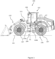
- Figure 1 shows a side view of a working machine 100 on a ground plane 101.
- the working machine 100 may be suitable for use in off-highway applications such as construction or agriculture.
- the working machine 100 is a wheel loader.
- the working machine 100 could be any suitable type of working machine such as a skid steer loader, a backhoe loader, or a tractor, which can accommodate the material handling assembly described in the following.
- Such working machines may be denoted as off-highway vehicles.
- the working machine 100 includes a superstructure 102, a chassis 104 and a ground-engaging propulsion structure 106.
- the superstructure 102 is mounted upon the chassis 104, which is mounted upon the ground-engaging propulsion structure 106.
- the ground-engaging propulsion structure 106 includes a plurality of wheels 107.
- the ground-engaging propulsion structure 106 could alternatively include, for example, a pair of continuous tracks.
- the working machine 100 includes an articulated steering arrangement.
- the chassis 104 includes a front chassis portion 104a articulated with respect to a rear chassis portion 104b about a steering axis X1.
- the front chassis portion 104a and the rear chassis portion 104b are each supported by a pair of wheels 107.
- the working machine 100 includes a steering actuator arrangement (not shown) to pivot the first and second chassis portions 104a, 104b relative to each other about the steering axis X1 so as to steer the working machine 100.
- the working machine 100 may include any suitable steering arrangement (e.g. rack and pinion steering).
- the superstructure 102 includes an operator station in the form of a cab 108.
- the cab 108 is directly mounted to the rear chassis portion 104b.
- another structure may be partially or wholly interposed between the cab 108 and the chassis 104.
- the cab 108 is intended to house a human operator of the working machine 100.
- the cab 108 may be replaced by an operator station that does not fully enclose an operator, such as a safety frame or canopy (not shown).
- the front chassis portion 104a includes a support 111.
- the working machine 100 includes a material handling assembly 110 pivotally mounted to the support 111 so as to be movable relative to the support 111.
- the material handling assembly 110 is provided for performing working operations (e.g. grading, loading or unloading).
- the material handling assembly 110 projects from the front chassis portion 104a in a travelling direction of the working machine 100), but may have any suitable connection to the chassis 104.
- connecting the material handling assembly 110 to the front chassis portion 104a enables the material handling assembly 110 to be pivoted about the steering axis X1 relative to the rear chassis portion 104b and the cab 108, which may help to simplify material handling operations.
- any suitable portion of the working machine 100 may include the support 111.
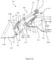
- Figure 2a shows an isolated side view of the material handling assembly 110 and the front chassis portion 104a.
- the material handling assembly 110 includes a working arm 112, a material handling implement 114, and a pivoting mechanism 116.
- the working arm 112 is pivotally mounted to the support 111 at a first pivot P1; i.e. such that the working arm 112 is pivotable relative to the support 111 about a corresponding first pivot axis (e.g. via one or more pins received in aligned apertures in the working arm 112 and support 111).
- the material handling implement 114 is pivotally mounted to the working arm 112 at a second pivot P2.
- the material handling implement 114 is a shovel, but in alternative embodiments may be a fork, rake, claw or any suitable material handling implement.
- first pivot P1 is proximate a first longitudinal end of the working arm 112
- second pivot P2 is proximate a second longitudinal end of the working arm 112, opposite the first longitudinal end.
- the pivoting mechanism 116 is pivotally mounted to the shovel 114 at a third pivot P3, and is pivotally mounted to the working arm 112 at a fourth pivot P4.
- the pivoting mechanism 116 is configured to pivot the shovel 114 about the second pivot P2 relative to the working arm 112.
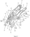
- Figure 3 shows an isometric view of the material handling assembly 110 without the shovel 114.
- the working arm 112 includes opposed first and second longitudinal structural members 118a, 118b spaced from each other and connected by a transverse connecting member 120.
- the structural members 118a, 118b extend substantially parallel to each other, and substantially parallel to a longitudinal direction of the working arm 112.
- the connecting member 120 extends substantially transversely to said longitudinal direction.
- Each structural member 118a, 118b is pivotally mounted to the support 111 at the first pivot P1, and to the shovel 114 at the second pivot P2.
- the first and second structural members 118a, 118b include first and second lateral ends 112a, 112b of the working arm 112 respectively.
- the pivoting mechanism 116 is interposed substantially centrally between the opposing lateral ends 112a, 112b of the working arm 112 (i.e. between the structural members 118a, 118b).
- the pivoting mechanism 116 may be offset from the centre whilst still being interposed between the opposing lateral ends 112a, 112b (i.e. the pivoting mechanism 116 may be closer to the first lateral end 112a relative to the second lateral end or vice versa).
- FIG 4 which shows a view from the cab 108 towards the shovel 114, that positioning the pivoting mechanism 116 between the lateral ends 112a, 112b of the working arm 112 helps to improve an operator's visibility of the shovel 114 and the surrounding environment, relative to if the pivoting mechanism 116 included two actuators for pivoting the shovel 114, each located at one of the lateral ends 112a, 112b, for example.
- positioning the pivoting mechanism 116 between the structural members 118a, 118b provides greater flexibility for the configuration of the links L1, L2, L3 and L4, and the first actuator A1, since the pivoting mechanism 116 is able to operate without contacting the structural members 118a, 118b.
- the pivoting mechanism 116 is supported by the connecting member 120, as will be discussed more in the following. In alternative embodiments (not shown), the pivoting mechanism 116 may be supported by any suitable portion of the working arm 112.
- the pivoting mechanism 116 includes a linkage having a first 'Z bar' link L1, a second 'chassis' link L2, a third 'tilt' link L3, a fourth 'implement' link L4, and a first actuator A1.
- the fourth link L4 may also be known as a shovel link.
- the first link L1 is pivotally mounted to the working arm 112 at the fourth pivot P4.
- the second link L2 is pivotally mounted to the first link L1 at a fifth pivot P5.
- the second link L2 is pivotally mounted to the support 111 at a sixth pivot P6.
- the first actuator A1 is pivotally mounted to the first link L1 at a seventh pivot P7.
- the third link L3 is pivotally mounted to the working arm 112 at an eighth pivot P8.
- the third link L3 is pivotally mounted to the fourth link L4 at a ninth pivot P9.
- the fourth link L4 is pivotally mounted to the first actuator A1 at a tenth pivot P10.
- the fourth link L4 is pivotally mounted to the shovel 114 at the third pivot P3.
- the fourth pivot P4 is substantially interposed between the fifth and seventh pivots P5, P7, such that the first link L1 acts as a bell crank.
- the third and fourth links L3, L4 form a four-bar linkage with the working arm 112 and the shovel 114.
- the fourth link L4 includes a cantilevered portion projecting from the ninth pivot P9, said cantilevered portion include the tenth pivot P10.
- the first actuator A1 is operable to extend and retract. Extension and retraction of the first actuator A1 respectively increases and decreases a distance between the seventh and tenth pivots P7, P10, so as to pivot the shovel 114 relative to the working arm 112 about the second pivot P2.
- the first actuator A1 is a hydraulic linear actuator (commonly referred to as a hydraulic ram or hydraulic cylinder), but in alternative embodiments, may be any suitable (e.g. electric or pneumatic) linear actuator.
- Extension of the first actuator A1 drives the fourth link L4 to pivot about the eighth pivot P8 via the third link L3 (anti-clockwise in Figure 2a ).
- Such pivoting of the fourth link L4 pivots the shovel 114 about the second pivot P2 (anti-clockwise in Figure 2a ).
- the shovel 114 pivots relative to the working arm 112 towards a dumping position (i.e. a position in which loose material contained within the shovel 114 is released therefrom due to gravity).
- the foregoing actions are reversed when the first actuator A1 is retracted such that the shovel 114 pivots relative to the working arm 112 away from the dumping position and towards a crowding position (i.e. a position in which loose material can be contained within the shovel 114).
- the material handling assembly 110 includes a pair of second actuators A2, each pivotally mounted to the support 111 at an eleventh pivot P11, and pivotally mounted to the working arm 112 at a twelfth pivot P12.
- Each second actuator A2 is operable to extend and retract. Extension and retraction of the second actuators A2 pivots the working arm 112 relative to the support 111 about the first pivot P1 so as to respectively raise and lower the shovel 114 relative to the ground plane 101 of the working machine 100.
- each second actuator A2 is a hydraulic ram or cylinder, but in alternative embodiments, may be any suitable (e.g. electric or pneumatic) linear actuator.
- the material handling assembly 110 may include a single second actuator A2 or more than two second actuators A2.
- the material handling assembly 110 may include an alternative actuator arrangement configured to pivot the working arm 112 relative to the support 111 about the first pivot P1 (e.g. a rotary actuator, such as a motor, at the first pivot P1).
- the pivoting mechanism 116 is configured to pivot the shovel 114 relative to the working arm 112 about the second pivot P2 via pivoting of the working arm 112 relative to the support 111 about the first pivot P1 (i.e. without operation of the first actuator A1).
- the shovel 114 pivots relative to the working arm 112 towards the dumping position.
- the foregoing actions are reversed when the working arm 112 is pivoted so as to lower the shovel 114 such that the shovel 114 pivots relative to the working arm 112 away from the dumping position towards the crowding position.
- the shovel 114 may pivot relative to the ground plane 101 towards the crowding position, and vice versa.
- the pivoting mechanism 116 is configured so as to inhibit the first link L1 and the first actuator A1 clashing across the entire lifting range of the material handling assembly 110.
- a portion of the first link L1 connecting the fourth and seventh pivots P4, P7 is substantially dogleg-shaped so as to prevent clashing with the first actuator A1 when the material handling assembly 110 is at or towards its lowermost height above the ground plane 101 (e.g. as shown in Figure 7 ).
- the links L1-L4 and first actuator A1 may have any suitable configuration in which the pivoting mechanism 116 pivots the shovel 114 relative to the working arm 112 about the second pivot P2 via pivoting of the working arm 112 relative to the support 111 about the first pivot P1, and via operation of the first actuator A1.
- the first actuator A1 may instead be directly pivotally mounted to the shovel 114 at the third pivot P3.
- the pivoting mechanism 116 may not include the third and fourth links L3, L4, although this may restrict the dumping angle.
- dumping angle refers to an angle between the ground plane 101 and a base 114a of the shovel 114, which is zero when the base 114a and ground plane are parallel, positive when the shovel 114 is pivoted towards a dumping position, and negative when pivoted towards a crowding position.
- “crowding angle” corresponds to the dumping angle with a change of sign (i.e. negative dumping angle equals a positive crowding angle and vice versa).
- the base 114a forms an angle of approximately 67 degrees with an axis X2 intersecting the second and third pivots P2, P3.
- the base 114a forms an angle of approximately 60 degrees with a back plate 114b of the shovel 114. Such dimensions are typical for loader shovels.
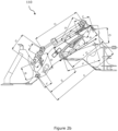
- Figure 2b shows the same view of the material handling assembly 110 and front chassis portion 104a of Figure 2a with reference numerals removed for clarity, and showing distances denoted A-S, where: A is the distance between the first and second pivots P1, P2; B is the distance between the second and third pivots P2, P3; C is the distance between the first and fourth pivots P1, P4; D is the distance between the first and twelfth pivots P1, P12; E is the distance between the second and twelfth pivots P2, P12; F is the distance between the second and eighth pivots P2, P8; G is the distance between the eighth and ninth pivots P8, P9; H is the distance between the third and tenth pivots P3, P10; I is the distance between the third and ninth pivots P3, P9; J is the distance between the ninth and tenth pivots P9, P10; K is the distance between the fifth and sixth pivots P5, P6; L is the distance between the fourth and fifth pivots P4, P5; M is the
- Table 1 includes lower, upper and example values for ratios of some of the distances A-S to the distance A, and some of the distances A-S to the distance K, according to exemplary embodiments.
- the distance ratios in Table 1 have been found to enable an improved breakout force of the shovel 114, and increased dumping angle of the shovel 114 across the lifting range of the material handling assembly 110, without significantly increasing the load imparted by the pivoting mechanism 116 on the support 111.
- such ratios have been found to enable the pivoting mechanism 116 to increase the crowding angle of the shovel 114 as the working arm is pivoted to lift the shovel 114, without operation of the first actuator A1, so as to help retain material held by the shovel 114.
- the distance A between the first and second pivots P1, P2 may be in the range of 2500 to 3500mm; optionally, in the range of 2700 to 3300mm, for example, approximately 3000mm.
- the distance K between the fifth and sixth pivots P5, P6 may be in the range of 400 to 700mm; optionally, in the range of 500 to 600mm, for example, approximately 550mm.
- the ratio C/A may be in the range of 0.19 to 0.23; optionally, in the range of 0.2 to 0.22.
- the ratio G/A may be in the range of 0.20 to 0.25; optionally in the range of 0.21 to 0.24.
- the ratio H/A may be in the range of 0.22 to 0.27; optionally in the range of 0.23 to 0.26.
- the ratio K/A may be in the range of 0.16 to 0.19; optionally in the range of 0.17 to 0.18.
- the ratio L/A may be in the range of 0.16 to 0.20; optionally in the range of 0.17 to 0.19.
- the ratio M/A may be in the range of 0.15 to 0.19; optionally, in the range of 0.16 to 0.18.
- the ratio N/A may be in the range of 0.32 to 0.39; optionally in the range of 0.33 to 0.37.
- the ratio S/A may be in the range of 0.53 to 0.65; optionally, in the range of 0.56 to 0.62.
- ratios and the corresponding ratios in Table 1 have been found to enhance an operator's visibility of the shovel 114 and the surrounding environment.
- the ratio L/K may be in the range of 0.93 to 1.13; optionally, in the range of 0.98 to 1.08.
- the ratio M/K may be in the range of 0.87 to 1.07; optionally in the range of 0.92 to 1.02.
- the ratio N/K may be in the range of 1.79 to 2.19; optionally, in the range of 1.89 to 2.09.
- the ratio R/K may be in the range of 0.99 to 1.21; optionally, in the range of 1.05 to 1.16.
- Extension and retraction of the first actuator A1 respectively increases and decreases the distance Q between the seventh and tenth pivots P7, P10. As such, when the first actuator A1 is fully extended, the distance Q is maximised, and when the first actuator A1 is fully retracted, the distance Q is minimised.
- a ratio Q max /A of the fully extended maximum distance Q to the distance A is in the range of 0.78 to 1.06; optionally in the range of 0.83 to 1.01; optionally in the range of 0.87 to 0.97, for example, approximately 0.92.
- a ratio Q min /A of the fully retracted minimum distance Q to the distance A is in the range of 0.47 to 0.64; optionally in the range of 0.50 to 0.61; optionally in the range of 0.53 to 0.58, for example, approximately 0.55.
- a ratio Q max /K of the fully extended maximum distance Q to the distance K is in the range of 4.44 to 6.01; optionally in the range of 4.70 to 5.75; optionally in the range of 4.96 to 5.49, for example approximately 5.2.
- a ratio Q min /K of the fully retracted minimum distance Q to the distance K is in the range of 2.67 to 3.62; optionally in the range of 2.83 to 3.46; optionally in the range of 2.99 to 3.30, for example approximately 3.1.
- Extension and retraction of the second actuator A2 respectively increases and decreases the distance P between the eleventh and twelfth pivots P11, P12. As such, when the second actuator A2 is fully extended, the distance P is maximised, and when the second actuator A2 is fully retracted, the distance P is minimised.
- a ratio P max /A of the fully extended maximum distance P to the distance A is in the range of 0.61 to 0.83; optionally, in the range of 0.65 to 0.80; optionally in the range of 0.69 to 0.76, for example, approximately 0.72.
- a ratio P min /A of the fully retracted minimum distance P to the distance A is in the range of 0.40 to 0.54; optionally, in the range of 0.42 to 0.51; optionally, in the range of 0.44 to 0.49, for example approximately 0.47.
- the working arm 112 includes first and second cantilever members 122, 124 projecting from the connecting member 120.
- the cantilever members 122, 124 project from the connecting member 120 in substantially opposite directions aligned with the longitudinal direction of the working arm 112.
- the first cantilever member 122 is pivotally mounted to the first link L1 at the fourth pivot P4.
- the second cantilever member 124 is pivotally mounted to the third link L3 at the eighth pivot P8.
- connecting the pivoting mechanism 116 to the working arm 112 via the connecting member 120 and the cantilever members 122, 124 helps to improve the visibility through the material handling assembly 110 towards the shovel 114 and of the surrounding environment for an operator in the cab 108, relative to a material handling assembly in which the pivoting mechanism is connected to a working arm via multiple connecting members, for example.
- each structural member 118a, 118b includes a plate extending between the first and second pivots P1, P2.
- the first cantilever member 122 includes two opposed plates extending between the connecting member 120 and the fourth pivot P4.
- the second cantilever member 124 includes two opposed plates extending between the connecting member 120 and the eighth pivot P8.
- the plates of the first cantilever member 122 are joined to the plates of the second cantilever member 124, e.g. by welding.
- the plates of the structural members 118a, 118b and the cantilever members 122, 124 are arranged substantially parallel to each other, and parallel to a plane substantially normal to the pivot axis of the shovel 114 relative to the working arm 112.
- the plates are formed from metal, e.g. steel, such as heat treated mild steel.
- the working arm 112 includes a plurality of cavities 126 spaced from each of the pivots P1-P12.
- the connecting member 120 includes an annular wall 127 partially defining two cavities 126a.
- the two cavities 126a extend substantially parallel to a pivot axis of the second pivot P2. As such, the cavities 126a help to reduce the weight of the material handling assembly 110 whilst maintaining sufficient structural rigidity of the working arm 112.
- the two cavities 126a are separated by a wall 128 extending between opposed sides of the annular wall 127, and substantially parallel to pivot axis of the second pivot P2.
- the wall 128 helps to increase the structural rigidity of the connecting member 120.
- each cavity 126a passes through both structural members 118a, 118b as well as the connecting member 120.
- Each cavity 126a has a substantially constant rectangular profile along an axis parallel to the pivot axis of the second pivot P2. In alternative embodiments, each cavity 126a may have any suitable constant or varying profile along said axis.
- An external surface of the annular wall 127 includes an opening 130 proximate the first actuator A1.
- the opening 130 faces the first actuator A1.
- the opening 130 leads to the two cavities 126a in the connecting member 120.
- the opening 130 extends through the annular wall 127 in a direction substantially perpendicular to the pivot axis of the second pivot P2.
- each structural member 118a, 118b includes a cavity 126b towards the second pivot P2.
- each cavity 126b extends through the corresponding structural member 118a, 118b.
- the working arm 112 may include any suitable arrangement of cavities 126.
- the working arm 112 may include one or more, or no, cavities 126 spaced from the pivots P1-P12.
- Figure 5 shows a schematic representation of a hydraulic circuit 140 of the working machine 100 for controlling the first actuator A1.
- the first actuator A1 is a hydraulic ram including a rod 142 having the tenth pivot P10, and a body 144 having the seventh pivot P7.
- a piston 143 is mounted to a distal end of the rod 142.
- the body 144 includes a first chamber 146 between the piston 143 and the seventh pivot P7, and a second chamber 148 between the piston 143 and the tenth pivot P10.
- the body 144 further includes a first port 150 in fluid communication with the first chamber 146, and a second port 152 in fluid communication with the second chamber 148.
- the hydraulic circuit 140 includes a hydraulic distributor 154 configured to supply hydraulic fluid (e.g.
- the hydraulic distributor 154 may include a reservoir of hydraulic fluid, a pump, and one or more valves for controlling the flow of hydraulic fluid.
- the hydraulic distributor 154 supplies hydraulic fluid to other hydraulic components of the working machine 100, such as the second actuator A2, and is located in the superstructure 102.
- the hydraulic distributor 154 supplies fluid to the first chamber 146 via the first port 150, such that the increased pressure in the first chamber 146 pushing against the piston 143 extends the rod 142 from the body 144.
- the rod 142 extends from the body 144, fluid exits from the second chamber 148 via the second port 152 into the hydraulic circuit 140 as the volume of the first chamber 146 increases. The foregoing actions are reversed to retract the first actuator A1.
- the rod 142 extends through the second chamber 148, reducing the cross-sectional area of the second chamber 148 compared to the first chamber 146.
- a greater volume of hydraulic fluid needs to be supplied to the first chamber 146 to fully extend the first actuator A1, relative to the volume of hydraulic fluid that needs to be supplied to the second chamber 148 to fully retract the first actuator A1. Therefore, for a constant flowrate of hydraulic fluid supplied by the hydraulic distributor 154, the first actuator A1 would normally take longer to fully extend than fully retract.
- the material handling assembly 110 includes a passage 156 connecting the first and second ports 150, 152 so as to transport fluid from the second to the first port 150, 152.
- the passage 156 bypasses the hydraulic distributor 154.
- a portion of the passage 156 may be fixed to the working arm 112.
- the passage 156 includes a one-way valve 158 configured to allow fluid to move from the second port 152 to the first port 150 via the passage 156, and inhibit fluid moving from the first port 150 to the second port 152 via the passage 156.
- hydraulic fluid is supplied to the first chamber 146 via the first port 150 both by the distributor 154 and the passage 156, increasing the speed of extension relative to if the passage 156 was not there. Since the passage 156 is wholly located in the material handling assembly 110, the distance travelled by hydraulic fluid from the second to the first port 152, 150 via the passage 156 is shortened, which reduces the pressure drop of the fluid.
- the passage 156 may not include the valve 158, and instead may transport fluid between the first and second ports 150, 152 in both directions.
- valve 158 is mounted to the connecting member 120. Although not shown, the valve 158 is mounted within the opening 130, which is proximate to the first actuator A1, which helps to reduce the length of the passage 156. In alternative embodiments (not shown), the valve 158 may be mounted to any suitable portion of the working arm 112.
- Figure 6 shows first and second plots PL1, PL2 of the position of the shovel 114 as the working arm 112 is pivoted about the first pivot P1, and in particular, the crowding angle of the shovel 114 relative to the ground plane 101 of the working machine 100 resulting from the action of the pivoting mechanism 116 (on the y-axis) versus the height of the second pivot P2 above the ground plane 101 resulting from the action of the second actuator A2 (on the x-axis), for an exemplary embodiment of the material handling assembly 110.
- both plots PL1, PL2 share a common crowding angle of the shovel 114 (43°), which corresponds to maximum crowding of the shovel 114 for this height, and is shown in Figure 7 .
- the shovel 114 is prevented from crowding further due to abutment between the shovel 114 and stops on the working arm 112.
- the first actuator A1 is not fully retracted in Figure 7 .
- the first plot PL1 corresponds to the maximum crowding position of the shovel 114 achievable by the pivoting mechanism 116 as the working arm 112 is raised from the position shown in Figure 7 .
- the first actuator A1 is retracted to maintain the shovel 114 against the stops on the working arm 12.
- the second pivot P2 reaches a height of approximately 901mm, the first actuator A1 is fully retracted.
- Such a position of the shovel 114 is ideal for transporting material.
- the crowding angle of the shovel 114 initially reduces slightly since the first actuator A1 has ceased retracting, before increasing again, reaching a peak of approximately 58° at a height of the second pivot P2 of approximately 3500mm.
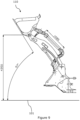
- Figure 9 which shows the maximum lift position of the second pivot P2
- the crowding angle of the shovel 114 reduces slightly to 57°.
- Such a position of the shovel 114 is ideal for lifting material over an obstacle (e.g. such as a wall of a container).
- the pivoting mechanism 116 When the pivoting mechanism 116 is controlled to maximise crowding of the shovel 114, as per the first plot PL1 of Figure 6 , the crowding angle of the shovel 114 is 57t1°for the majority of the lifting range of the working arm 112 (i.e. for heights of the second pivot P2 between approximately 900 to 4350mm), and is thus substantially constant over this range.
- Such a substantially constant crowding angle of the shovel 114 results from the pivoting mechanism 116 pivoting the shovel 114 relative to the working arm 112 towards a dumping position when the working arm 112 is raised and vice versa (i.e. without operation of the first actuator A1).
- the pivoting mechanism 116 has similar functionality to a parallel linkage mechanism.
- the second plot PL2 in Figure 6 shows the crowding angle of the shovel 114 as the working arm 112 is raised from the position shown in Figure 7 without operation of the first actuator A1 (i.e. for a constant distance between the seventh and tenth pivots P7, P10).
- the crowding angle of the shovel 114 increases until peaking at a height of the second pivot P2 of approximately 3500mm, and subsequently reducing as the second pivot P2 is raised above 3500mm to its maximum height of 4350mm, in a similar manner to the first plot PL1.
- the pivoting mechanism 116 is configured to increase the crowding angle of the shovel 114 relative to the ground plane 101 when the second pivot P2 is raised, without operation of the first actuator A1, across approximately 85% of the lifting range of the working arm 112.
- the pivoting mechanism 116 may be configured to increase the crowding angle of the shovel 114 relative to the ground plane 101 when the second pivot P2 is raised, without operation of the first actuator A1, across 60% or more of the lifting range of the working arm 112; optionally, across 70% or more of the lifting range of the working arm 112; optionally, across 80% or more of the lifting range of the working arm 112.
- 'lifting range' refers to the range of heights of the second pivot P2 above the ground plane 101 achievable via pivoting of the working arm 112 relative to the support 111 about the first pivot P1.
- the lifting range corresponds to the range of heights of the second pivot P2 above the ground plane 101 between full retraction and full extension of the second actuators A2.
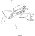
- Figure 10 shows the maximum dumping position of the shovel 114 at the maximum lift position of the second pivot P2.
- the maximum dumping angle of the shovel 114 for the maximum lift position is approximately 50°.
- Such a position of the shovel 114 is ideal for efficiently dumping material over an obstacle into a container.
- the maximum dumping angle of the shovel 114 relative to the ground plane 101 at the maximum lift position may be in the range of 40 to 60 degrees; optionally, 45 to 55 degrees.
- the pivot angle range of the shovel 114 (i.e. between maximum crowding angle and maximum dumping angle) is approximately 107 degrees. In some embodiments, the pivot angle range of the shovel 114 at the maximum lift position of the second pivot P2 may be in the range of 90 to 120 degrees, optionally, 100 to 110 degrees.
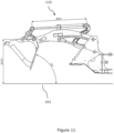
- Figure 11 shows the maximum dumping position of the shovel 114 at a maximum horizontal reach position of the second pivot P2 (i.e. when an axis intersecting the first and second pivots P1, P2 is parallel to the ground plane 101).
- this maximum dumping angle is approximately 70° as shown in Figure 11 .
- Such a maximum dumping angle is beneficial for collecting material, such as a harvested crop, particularly when the material handling implement 114 is a fork or rake.
- the maximum dumping angle of the shovel 114 relative to the ground plane 101 at the maximum horizontal reach position may be in the range of 50 to 80 degrees; optionally in the range of 60 to 75 degrees.
- the pivot angle range of the shovel 114 is approximately 127 degrees. In some embodiments, the pivot angle range of the shovel 114 at the maximum horizontal reach position of the second pivot P2 may be in the range of 110 to 140 degrees; optionally, 120 to 130 degrees.
- the overall maximum dumping angle of the shovel 114 (i.e. the maximum achievable dumping angle of the shovel 114 across the entire lifting range of the working arm 112) is approximately 83 degrees.
- the material handling assembly 110 is capable of providing such an overall maximum dumping angle when the second pivot P2 is at its lowermost position relative to the ground plane 101 (i.e. by fully retracting the second actuators A2).
- the overall maximum dumping angle of the shovel 114 relative to the ground plane 101 may be in the range of 60 to 90 degrees; optionally, in the range of 70 to 85 degrees; optionally in the range of 80 to 85 degrees.
- the pivot range of the shovel 114 is approximately 126 degrees.
Landscapes
- Engineering & Computer Science (AREA)
- Mechanical Engineering (AREA)
- Mining & Mineral Resources (AREA)
- Civil Engineering (AREA)
- General Engineering & Computer Science (AREA)
- Structural Engineering (AREA)
- Shovels (AREA)
- Jib Cranes (AREA)
- Forklifts And Lifting Vehicles (AREA)
Applications Claiming Priority (1)
| Application Number | Priority Date | Filing Date | Title |
|---|---|---|---|
| GB2317121.8A GB2635347A (en) | 2023-11-08 | 2023-11-08 | Working machine |
Publications (1)
| Publication Number | Publication Date |
|---|---|
| EP4553232A1 true EP4553232A1 (de) | 2025-05-14 |
Family
ID=89164831
Family Applications (1)
| Application Number | Title | Priority Date | Filing Date |
|---|---|---|---|
| EP24211385.0A Pending EP4553232A1 (de) | 2023-11-08 | 2024-11-07 | Arbeitsmaschine |
Country Status (3)
| Country | Link |
|---|---|
| US (1) | US20250146245A1 (de) |
| EP (1) | EP4553232A1 (de) |
| GB (1) | GB2635347A (de) |
Families Citing this family (1)
| Publication number | Priority date | Publication date | Assignee | Title |
|---|---|---|---|---|
| JP1731215S (ja) * | 2022-01-19 | 2022-12-02 | ローダ用バケット作業機 |
Citations (3)
| Publication number | Priority date | Publication date | Assignee | Title |
|---|---|---|---|---|
| DE1913236A1 (de) * | 1968-03-18 | 1970-02-05 | Bofors Ab | Vorrichtung bei Schaufeln fuer Verlademaschinen |
| GB2353270A (en) * | 1999-06-21 | 2001-02-21 | Caterpillar Inc | Linkage arrangement for a work machine |
| US9447560B2 (en) * | 2011-12-27 | 2016-09-20 | Doosan Infacore Co., Ltd. | Parallel linkage-type working apparatus for construction equipment |
Family Cites Families (3)
| Publication number | Priority date | Publication date | Assignee | Title |
|---|---|---|---|---|
| US7736117B2 (en) * | 2007-10-31 | 2010-06-15 | Caterpillar Inc. | Linkage assembly |
| CN102518155A (zh) * | 2012-01-04 | 2012-06-27 | 江苏柳工机械有限公司 | 挖掘装载机装载端正转八连杆工作装置 |
| US8807909B2 (en) * | 2012-10-12 | 2014-08-19 | Caterpillar Inc. | Tilting system for loader machine |
-
2023
- 2023-11-08 GB GB2317121.8A patent/GB2635347A/en active Pending
-
2024
- 2024-11-07 EP EP24211385.0A patent/EP4553232A1/de active Pending
- 2024-11-08 US US18/942,338 patent/US20250146245A1/en active Pending
Patent Citations (3)
| Publication number | Priority date | Publication date | Assignee | Title |
|---|---|---|---|---|
| DE1913236A1 (de) * | 1968-03-18 | 1970-02-05 | Bofors Ab | Vorrichtung bei Schaufeln fuer Verlademaschinen |
| GB2353270A (en) * | 1999-06-21 | 2001-02-21 | Caterpillar Inc | Linkage arrangement for a work machine |
| US9447560B2 (en) * | 2011-12-27 | 2016-09-20 | Doosan Infacore Co., Ltd. | Parallel linkage-type working apparatus for construction equipment |
Also Published As
| Publication number | Publication date |
|---|---|
| GB2635347A (en) | 2025-05-14 |
| GB202317121D0 (en) | 2023-12-20 |
| US20250146245A1 (en) | 2025-05-08 |
Similar Documents
| Publication | Publication Date | Title |
|---|---|---|
| US6796762B2 (en) | Boom and linkage mechanism for skid-steer loader | |
| EP2762642B1 (de) | Kompaktladeraufzugsgestängeanordnung | |
| US7264435B2 (en) | Lift boom assembly | |
| EP4553232A1 (de) | Arbeitsmaschine | |
| EP2280122B1 (de) | Vertikale hebearmvorrichtung | |
| US3472405A (en) | Material handling apparatus | |
| JP2004224458A (ja) | 自走式作業機械 | |
| US4431363A (en) | Articulated material handling machine | |
| JP3133793B2 (ja) | リフト・ローダブーム装置およびリフト・ローダブーム装置を用いた作業具移動方法 | |
| US6698114B2 (en) | Lift arm support and storage construction for small loader | |
| US20130084155A1 (en) | Material Handling Machine | |
| EP1604941A1 (de) | Selbstfahrende arbeitsmaschine | |
| US10906448B2 (en) | Dumper vehicle | |
| CN108678044B (zh) | 滑移装载垂直举升装置 | |
| US11654815B2 (en) | Closed center hoist valve with snubbing | |
| US8807909B2 (en) | Tilting system for loader machine | |
| US4411584A (en) | Optimized earthworking tool operating linkage | |
| US3517846A (en) | High lift bucket | |
| US12559014B2 (en) | Dual bin high dump transport vehicle | |
| EP0084067A2 (de) | Fahrzeug zum Laden und Baggern | |
| GB2616301A (en) | A carriage assembly | |
| EP4015441B1 (de) | Wagenanordnung | |
| NZ744265A (en) | A dumper vehicle | |
| WO2003038199A1 (en) | Lift arm support and storage construction for small loader |
Legal Events
| Date | Code | Title | Description |
|---|---|---|---|
| PUAI | Public reference made under article 153(3) epc to a published international application that has entered the european phase |
Free format text: ORIGINAL CODE: 0009012 |
|
| STAA | Information on the status of an ep patent application or granted ep patent |
Free format text: STATUS: REQUEST FOR EXAMINATION WAS MADE |
|
| 17P | Request for examination filed |
Effective date: 20241107 |
|
| AK | Designated contracting states |
Kind code of ref document: A1 Designated state(s): AL AT BE BG CH CY CZ DE DK EE ES FI FR GB GR HR HU IE IS IT LI LT LU LV MC ME MK MT NL NO PL PT RO RS SE SI SK SM TR |
|
| P01 | Opt-out of the competence of the unified patent court (upc) registered |
Free format text: CASE NUMBER: UPC_APP_0018438_4553232/2025 Effective date: 20251219 |