EP4553229A1 - Blowing accessory equipment for a sweeper or similar street cleaning machine - Google Patents
Blowing accessory equipment for a sweeper or similar street cleaning machine Download PDFInfo
- Publication number
- EP4553229A1 EP4553229A1 EP23383140.3A EP23383140A EP4553229A1 EP 4553229 A1 EP4553229 A1 EP 4553229A1 EP 23383140 A EP23383140 A EP 23383140A EP 4553229 A1 EP4553229 A1 EP 4553229A1
- Authority
- EP
- European Patent Office
- Prior art keywords
- air
- sweeper
- tube
- cleaning machine
- machine
- Prior art date
- Legal status (The legal status is an assumption and is not a legal conclusion. Google has not performed a legal analysis and makes no representation as to the accuracy of the status listed.)
- Granted
Links
Images
Classifications
-
- E—FIXED CONSTRUCTIONS
- E01—CONSTRUCTION OF ROADS, RAILWAYS, OR BRIDGES
- E01H—STREET CLEANING; CLEANING OF PERMANENT WAYS; CLEANING BEACHES; DISPERSING OR PREVENTING FOG IN GENERAL CLEANING STREET OR RAILWAY FURNITURE OR TUNNEL WALLS
- E01H1/00—Removing undesirable matter from roads or like surfaces, with or without moistening of the surface
- E01H1/08—Pneumatically dislodging or taking-up undesirable matter or small objects; Drying by heat only or by streams of gas; Cleaning by projecting abrasive particles
- E01H1/0809—Loosening or dislodging by blowing ; Drying by means of gas streams
-
- E—FIXED CONSTRUCTIONS
- E01—CONSTRUCTION OF ROADS, RAILWAYS, OR BRIDGES
- E01H—STREET CLEANING; CLEANING OF PERMANENT WAYS; CLEANING BEACHES; DISPERSING OR PREVENTING FOG IN GENERAL CLEANING STREET OR RAILWAY FURNITURE OR TUNNEL WALLS
- E01H1/00—Removing undesirable matter from roads or like surfaces, with or without moistening of the surface
- E01H1/08—Pneumatically dislodging or taking-up undesirable matter or small objects; Drying by heat only or by streams of gas; Cleaning by projecting abrasive particles
- E01H1/0809—Loosening or dislodging by blowing ; Drying by means of gas streams
- E01H1/0818—Loosening or dislodging by blowing ; Drying by means of gas streams in apparatus with mechanical loosening or feeding instruments, e.g. brushes, scrapers
-
- E—FIXED CONSTRUCTIONS
- E01—CONSTRUCTION OF ROADS, RAILWAYS, OR BRIDGES
- E01H—STREET CLEANING; CLEANING OF PERMANENT WAYS; CLEANING BEACHES; DISPERSING OR PREVENTING FOG IN GENERAL CLEANING STREET OR RAILWAY FURNITURE OR TUNNEL WALLS
- E01H1/00—Removing undesirable matter from roads or like surfaces, with or without moistening of the surface
- E01H1/12—Hand implements, e.g. litter pickers
Definitions
- the invention as expressed in the title of the present specification, relates to a blowing accessory equipment for a sweeper or similar street cleaning machine, providing advantages and characteristics, which are described in detail below, which are an improvement in the current state of the art.
- the object of the present invention is an air blowing accessory that, made up of a set of elements that, at least, comprises a flexible air-conducting tube with a water-conducting tube and a control handle, defines equipment especially designed for its secure incorporation or removably attached to a sweeping or similar street cleaning machine and using the air expelled by the sweeper or cleaning equipment itself to channel it, through the flexible tube, and use of this air by an operator located next to the machine to blow the waste and direct it towards the suction or transport opening, thereby avoiding the use of the traditional portable blower.
- the field of application of the present invention falls within the sector of the industry dedicated to the manufacture of machines, apparatus, devices and equipment for street cleaning, focusing particularly on the field of those intended for cleaning by applying air.
- These particles have various emission sources.
- One of these emission sources is generated when the particles deposited in the soil are removed; when the particles are stirred up, the dust generated contains high proportions of fine dust particles, called PM2.5 and PM10.
- the sprayers or nebulizers of said water are located close to the generation and transport of the air that contains these particles.
- blowers lack any fine dust collection system, which means they generate a high amount of PM2.5 and PM10 particles, which are toxic to passers-by and to the operators who operate the blower.
- the operator of the blower must carry a backpack that bears the weight of the engine and fuel tank (in the case of blowers with a heat engine) or the batteries and electric motor (in the case of electric blowers). In both cases, the weight and noise borne by the operator are considerable.
- Sweepers, and cleaning machines in general have an integrated water tank, to be able to use them to collect fine dust.
- sweepers in general and vacuum sweepers in particular also have a turbine to generate suction air by creating a vacuum; this air helps to suck up waste, including fine dust carrying PM2.5 and PM10, and place this waste in the storage hopper.
- the objective of the present invention is, therefore, to provide a practical solution to the aforementioned problems by developing a blowing accessory equipment that can be incorporated into the sweeping or street cleaning machine itself and use the air expelled thereby to channel it and that can be used by an operator to blow the waste and direct it towards the suction or transport opening, avoiding the use of the traditional portable blower.
- blowing accessory equipment for a sweeper or similar street cleaning machine that the invention proposes is configured as an optimal solution to the aforementioned objectives which, in turn, represents an improvement of the current state of the art, the characterising details being that which make it possible and that distinguish it, conveniently contained in the final claims that accompany this description.
- the invention proposes, as noted above, an air blowing accessory specially designed to be securely incorporated or attached to a sweeping or similar street cleaning machine and use of the air expelled by the sweeper or cleaning equipment to channel it and use that air to blow the waste and direct it towards the suction or transport opening, thereby avoiding the use of a traditional portable blower.
- the blowing accessory equipment for a sweeper or similar street cleaning machine that is the object of the invention essentially comprises a flexible air-conducting tube capable of channelling the air expelled by the sweeper or cleaning equipment and using it to blow waste and direct it towards the suction opening of the machine.
- said flexible tube is connected, at one end, to the turbine of the sweeper while at the opposite end it has an air outlet opening.
- the equipment optionally comprises a small water conduit, which is also flexible, that allows the water tank of the sweeper or cleaning machine to be used to incorporate sprayed water into the air blown through the flexible air tube and thus capture fine dust as is done with the brushes of the sweeper and inside the suction opening.
- said water conduit is connected at one end to the water tank of the sweeper while at the opposite end it is joined to the outlet of the flexible air tube.
- the water tube is joined along its entire length, for example by means of flanges, to the flexible air tube.
- the equipment may comprise various means such as a mechanical or piloted mechanism, or a handle incorporated into the tube itself to totally or partially cut off the air flow at the discretion of the operator, such that the air expelled by the turbine can be used totally or partially for blowing.
- the amount of air that is not used for blowing will exit through the normal conduit of the cleaning equipment.
- the flexible air tube can be of different lengths, depending on the requirements of each job.
- the equipment comprises a rotating pole that, attached to the upper portion of the sweeper where the turbine is usually located, helps to move and distribute the weight of said tube and avoid cars parked on the pavement.
- the equipment further comprises a fastening element such as a harness that the operator can wear at the waist, to help bear the weight of the final portion of the suction tube.
- a fastening element such as a harness that the operator can wear at the waist, to help bear the weight of the final portion of the suction tube.
- the weight of the flexible tube can be around 0.75 kg/m and the final tube with the handle, around 1 kg. These are weights that, in any case, are much lower than those of a portable blower that constitutes the current state of the art.
- the blowing equipment of the invention comprises the incorporation of a small compressor or a small turbine for generating high-pressure air.
- the weight and noise will be in the cleaning machine and not on the back of the operator and the incorporation of water in the blowing will continue to be carried out through the conduit attached to the flexible air-channelling tube.
- blowing accessory equipment for a sweeper or street cleaning machine of the invention comprising that which is described in detail below.
- the equipment (1) of the invention applicable for incorporation thereof into a sweeping or street cleaning machine (2) equipped with at least one water tank (3), for example to spray it through nozzles (4) located next to rotating brushes (5), and equipped or not with a turbine (6) generating pressurised air, it essentially comprises a flexible air-conducting tube (7) that is connected, at a proximal end (7a), to a turbine (6) of the sweeping machine (2) itself, or to a turbine or air compressor installed for this purpose in the machine (2), and the opposite end or distal end (7b) of which has an air outlet opening (8), enabling the air expelled by said turbine (6) of the machine (2) to be channelled and used, handled by an operator, to blow waste and direct it, preferably, towards the suction area (2a) of the machine (2) itself.
- the equipment (1) of the invention further comprises a water conduit (9), also flexible, which is connected at a proximal end (9a) to the water tank (3) of the machine (2) and joined at the distal end (9b) to the air outlet opening (8) of the flexible air tube (7) enabling sprayed water to be incorporated into the air blown through the flexible air tube (7).
- a water conduit (9) also flexible, which is connected at a proximal end (9a) to the water tank (3) of the machine (2) and joined at the distal end (9b) to the air outlet opening (8) of the flexible air tube (7) enabling sprayed water to be incorporated into the air blown through the flexible air tube (7).
- the water conduit (9) is attached along the entire length thereof to the flexible air tube (7), for example by means of flanges (10) distributed along the same and has a tap (11) to regulate the passage of the water.
- the flexible air tube (7) comprises means for regulating the air outlet such as a butterfly valve (12) and/or a control handle (13) incorporated into the tube (7) itself to regulate or cut the air flow completely or partially at will.
- a butterfly valve (12) and/or a control handle (13) incorporated into the tube (7) itself to regulate or cut the air flow completely or partially at will.
- valve (12) and/or the control handle (13) have piloted mechanisms and are connected with electrical cables (14) that provide electrical power from the machine (2), said cables being attached to the flexible tube (7) through the aforementioned fastening flanges (10).
- the inclusion of a section of rigid tube (7c) where the handle (13) is incorporated is contemplated between the distal end (7b) of the flexible air tube (7) and the air outlet opening (8).
- the air outlet opening (8) has a conical configuration to force a Venturi effect that increases the outlet pressure of the air.
- the blowing equipment (1) comprises a rotating pole (15) that is fastened to the upper portion of the machine (2), where the turbine (6) is usually located, in which the initial section is fastened after the proximal end (7a) of the flexible air tube (7) helping to move and distribute the weight of said tube.
- the equipment includes a securing element for securing to the body of the operator, such as a waist harness (16), to hang the flexible air tube (7) and help bear the weight of the final portion thereof.
- a securing element for securing to the body of the operator, such as a waist harness (16), to hang the flexible air tube (7) and help bear the weight of the final portion thereof.
- the equipment (1) described can be incorporated into the machine (2) either permanently or optionally with easily removable fastening elements.
Landscapes
- Engineering & Computer Science (AREA)
- Architecture (AREA)
- Civil Engineering (AREA)
- Structural Engineering (AREA)
- Cleaning In General (AREA)
- Cleaning Of Streets, Tracks, Or Beaches (AREA)
Abstract


Description
- The invention, as expressed in the title of the present specification, relates to a blowing accessory equipment for a sweeper or similar street cleaning machine, providing advantages and characteristics, which are described in detail below, which are an improvement in the current state of the art.
- The object of the present invention is an air blowing accessory that, made up of a set of elements that, at least, comprises a flexible air-conducting tube with a water-conducting tube and a control handle, defines equipment especially designed for its secure incorporation or removably attached to a sweeping or similar street cleaning machine and using the air expelled by the sweeper or cleaning equipment itself to channel it, through the flexible tube, and use of this air by an operator located next to the machine to blow the waste and direct it towards the suction or transport opening, thereby avoiding the use of the traditional portable blower.
- The field of application of the present invention falls within the sector of the industry dedicated to the manufacture of machines, apparatus, devices and equipment for street cleaning, focusing particularly on the field of those intended for cleaning by applying air.
- Currently, it is noted that particles called PM2.5 and PM10 are harmful and toxic to human health.
- These particles have various emission sources. One of these emission sources is generated when the particles deposited in the soil are removed; when the particles are stirred up, the dust generated contains high proportions of fine dust particles, called PM2.5 and PM10.
- For street cleaning functions, it is common to use mechanical vacuum or broom sweepers, which have brushes that remove the particles and channel them towards a suction opening or towards a mechanical transport element towards a storage hopper for the waste. This movement of the brushes, upon scrapping the floor, generates the aforementioned PM2.5 and PM10 particles.
- To mitigate the emission of these particles, all sweepers must have a system for capturing harmful particles that generally consists of the placement of filters and, mainly, the incorporation of sprayed pressurised water that helps capture the fine dust containing the particles PM2.5 and PM10.
- The sprayers or nebulizers of said water are located close to the generation and transport of the air that contains these particles.
- However, although the sweepers are certified to capture PM2.5 and PM10 particles during their work, it is common, to obtain greater production, such that personnel are used in front of these sweepers with a manual and portable blower, which helps channel the furthest waste and bring it closer to the brushes or the suction or mechanical transport opening of the sweeper.
- These blowers lack any fine dust collection system, which means they generate a high amount of PM2.5 and PM10 particles, which are toxic to passers-by and to the operators who operate the blower.
- Furthermore, the operator of the blower must carry a backpack that bears the weight of the engine and fuel tank (in the case of blowers with a heat engine) or the batteries and electric motor (in the case of electric blowers). In both cases, the weight and noise borne by the operator are considerable.
- The operator must also bear with his arm the weight of a turbine incorporated in a blower tube.
- Therefore, three problems are identified with the use of blowers in front of sweepers:
- Generating a high amount of PM2.5 and PM10 particles, which are toxic to health.
- The operator handling the blower bearing considerable weight (on the back and arm).
- The operator and bystanders bearing considerable noise.
- Sweepers, and cleaning machines in general, have an integrated water tank, to be able to use them to collect fine dust.
- Furthermore, sweepers in general and vacuum sweepers in particular, also have a turbine to generate suction air by creating a vacuum; this air helps to suck up waste, including fine dust carrying PM2.5 and PM10, and place this waste in the storage hopper.
- However, all the air sucked in is expelled back outside and is not completely clean as it contains wet dust particles.
- The objective of the present invention is, therefore, to provide a practical solution to the aforementioned problems by developing a blowing accessory equipment that can be incorporated into the sweeping or street cleaning machine itself and use the air expelled thereby to channel it and that can be used by an operator to blow the waste and direct it towards the suction or transport opening, avoiding the use of the traditional portable blower.
- Furthermore, and as a reference to the current state of the art, it must be noted that at least the applicant is unaware of the existence of any other equipment, or of any other invention of similar application, which presents technical, structural and constitutive features that are the same or similar to those presented by that which is claimed herein.
- The blowing accessory equipment for a sweeper or similar street cleaning machine that the invention proposes is configured as an optimal solution to the aforementioned objectives which, in turn, represents an improvement of the current state of the art, the characterising details being that which make it possible and that distinguish it, conveniently contained in the final claims that accompany this description.
- Specifically, the invention proposes, as noted above, an air blowing accessory specially designed to be securely incorporated or attached to a sweeping or similar street cleaning machine and use of the air expelled by the sweeper or cleaning equipment to channel it and use that air to blow the waste and direct it towards the suction or transport opening, thereby avoiding the use of a traditional portable blower.
- To this end, and more specifically, the blowing accessory equipment for a sweeper or similar street cleaning machine that is the object of the invention essentially comprises a flexible air-conducting tube capable of channelling the air expelled by the sweeper or cleaning equipment and using it to blow waste and direct it towards the suction opening of the machine. To do this, said flexible tube is connected, at one end, to the turbine of the sweeper while at the opposite end it has an air outlet opening.
- In addition, the equipment optionally comprises a small water conduit, which is also flexible, that allows the water tank of the sweeper or cleaning machine to be used to incorporate sprayed water into the air blown through the flexible air tube and thus capture fine dust as is done with the brushes of the sweeper and inside the suction opening. To do this, said water conduit is connected at one end to the water tank of the sweeper while at the opposite end it is joined to the outlet of the flexible air tube.
- Preferably, the water tube is joined along its entire length, for example by means of flanges, to the flexible air tube.
- In order to regulate the blowing air, the equipment may comprise various means such as a mechanical or piloted mechanism, or a handle incorporated into the tube itself to totally or partially cut off the air flow at the discretion of the operator, such that the air expelled by the turbine can be used totally or partially for blowing. The amount of air that is not used for blowing will exit through the normal conduit of the cleaning equipment.
- In this way, the operator who handles the blowing equipment does not bear weight or noise, since they simply use two flexible tubes with a control handle incorporated at the end or final portion of the air and water outlet, which can be rigid and of different sizes and shapes, to better direct the air.
- The flexible air tube can be of different lengths, depending on the requirements of each job.
- Optionally, to help the operator minimise the weight of the flexible tube, for example to bypass and pass over the top of vehicles parked on the road, the equipment comprises a rotating pole that, attached to the upper portion of the sweeper where the turbine is usually located, helps to move and distribute the weight of said tube and avoid cars parked on the pavement.
- Optionally, the equipment further comprises a fastening element such as a harness that the operator can wear at the waist, to help bear the weight of the final portion of the suction tube.
- In any case, the weight of the flexible tube can be around 0.75 kg/m and the final tube with the handle, around 1 kg. These are weights that, in any case, are much lower than those of a portable blower that constitutes the current state of the art.
- Furthermore, the source of the noise produced by the turbine that provides the force that pushes the air through the blower is moved away from the operator, since said turbine is located in the cleaning machine itself and continues to be the same as the usual one.
- Optionally, when the sweeper or street cleaning machine does not have a turbine, the blowing equipment of the invention comprises the incorporation of a small compressor or a small turbine for generating high-pressure air. As in the previous case, the weight and noise will be in the cleaning machine and not on the back of the operator and the incorporation of water in the blowing will continue to be carried out through the conduit attached to the flexible air-channelling tube.
- To complete the description provided herein, and for the purpose of helping to make the features of the invention more readily understandable, this description is accompanied by drawings constituting an integral part of the same, which by way of illustration and not limitation represents the following:
-
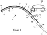
Figure 1 shows a schematic view of an example of the blowing tube with some of the main elements that comprise the equipment object of the invention, including a harness to hold said tube on the hip; and -
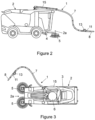
Figures 2 and 3 show, in respective schematic side elevation and top plan views, an example of the equipment of the invention incorporated in a sweeping machine, showing the elements it comprises and the arrangement thereof. - In view of the aforementioned figures, and in accordance with the adopted numbering, one may observe therein a non-limiting exemplary embodiment of the blowing accessory equipment for a sweeper or street cleaning machine of the invention, comprising that which is described in detail below.
- As such, as seen in said figures, the equipment (1) of the invention, applicable for incorporation thereof into a sweeping or street cleaning machine (2) equipped with at least one water tank (3), for example to spray it through nozzles (4) located next to rotating brushes (5), and equipped or not with a turbine (6) generating pressurised air, it essentially comprises a flexible air-conducting tube (7) that is connected, at a proximal end (7a), to a turbine (6) of the sweeping machine (2) itself, or to a turbine or air compressor installed for this purpose in the machine (2), and the opposite end or distal end (7b) of which has an air outlet opening (8), enabling the air expelled by said turbine (6) of the machine (2) to be channelled and used, handled by an operator, to blow waste and direct it, preferably, towards the suction area (2a) of the machine (2) itself.
- In one embodiment, the equipment (1) of the invention further comprises a water conduit (9), also flexible, which is connected at a proximal end (9a) to the water tank (3) of the machine (2) and joined at the distal end (9b) to the air outlet opening (8) of the flexible air tube (7) enabling sprayed water to be incorporated into the air blown through the flexible air tube (7).
- Preferably, the water conduit (9) is attached along the entire length thereof to the flexible air tube (7), for example by means of flanges (10) distributed along the same and has a tap (11) to regulate the passage of the water.
- Preferably, the flexible air tube (7) comprises means for regulating the air outlet such as a butterfly valve (12) and/or a control handle (13) incorporated into the tube (7) itself to regulate or cut the air flow completely or partially at will.
- Preferably, the valve (12) and/or the control handle (13) have piloted mechanisms and are connected with electrical cables (14) that provide electrical power from the machine (2), said cables being attached to the flexible tube (7) through the aforementioned fastening flanges (10).
- Preferably, the inclusion of a section of rigid tube (7c) where the handle (13) is incorporated is contemplated between the distal end (7b) of the flexible air tube (7) and the air outlet opening (8).
- Preferably, the air outlet opening (8) has a conical configuration to force a Venturi effect that increases the outlet pressure of the air.
- Optionally, the blowing equipment (1) comprises a rotating pole (15) that is fastened to the upper portion of the machine (2), where the turbine (6) is usually located, in which the initial section is fastened after the proximal end (7a) of the flexible air tube (7) helping to move and distribute the weight of said tube.
- Optionally, the equipment includes a securing element for securing to the body of the operator, such as a waist harness (16), to hang the flexible air tube (7) and help bear the weight of the final portion thereof.
- The equipment (1) described can be incorporated into the machine (2) either permanently or optionally with easily removable fastening elements.
- Having sufficiently described the nature of the present invention, as well as the ways in which it may be implemented, it is not considered necessary to elaborate on the explanation thereof in order for a person skilled in the art to understand the scope of the invention and the advantages derived therefrom.
Claims (8)
- Blowing accessory equipment for a sweeper or similar street cleaning machine, applicable for incorporation thereof into a sweeping or street cleaning machine (2) equipped with at least one water tank (3) and equipped or not with a turbine (6) generating pressurised air, characterised in that it comprises a flexible air-conducting tube (7) that is connected, at a proximal end (7a), to a turbine (6) of the machine (2) itself, or to a turbine or air compressor installed for this purpose in the machine (2), and the distal end (7b) of which has an air outlet opening (8), enabling the air expelled by said turbine (6) to be channelled and, handled by an operator, used to blow waste.
- Blowing accessory equipment for a sweeper or similar street cleaning machine, according to claim 1, characterised in that it comprises a water conduit (9), also flexible, which is connected at a proximal end (9a) to the water tank (3) of the machine (2) and is joined at the distal end (9b) to the air outlet opening (8) of the flexible air tube (7), enabling sprayed water to be incorporated into the air blown through the flexible air tube (7).
- Blowing accessory equipment for a sweeper or similar street cleaning machine, according to claim 1 or 2, characterised in that the flexible air tube (7) comprises means such as a butterfly valve (12) and/or a control handle (13) incorporated into the tube (7) itself to regulate or cut off the air flow totally or partially at will.
- Blowing accessory equipment for a sweeper or similar street cleaning machine, according to claim 3, characterised in that the valve (12) and/or the control handle (13) have piloted mechanisms and are connected with electrical cables (14) that provide electrical power from the machine (2), said cables being attached to the flexible tube (7) through the aforementioned fastening flanges (10).
- Blowing accessory equipment for a sweeper or similar street cleaning machine, according to any of claims 3 or 4, characterised in that the inclusion of a section of rigid tube (7c) where the handle (13) is incorporated is contemplated between the distal end (7b) of the flexible air tube (7) and the air outlet opening (8).
- Blowing accessory equipment for a sweeper or similar street cleaning machine, according to any of the preceding claims, characterised in that the air outlet opening (8) is conical to force a Venturi effect that increases the outlet pressure of the air.
- Blowing accessory equipment for a sweeper or similar street cleaning machine, according to any of the preceding claims, characterised in that it comprises a rotating pole (15) fixed to the upper portion of the machine (2), in which the initial section is fastened after the proximal end (7a) of the flexible air tube (7).
- Blowing accessory equipment for a sweeper or similar street cleaning machine, according to any of the preceding claims, characterised in that it comprises a securing element for securing to the body of the operator such as a waist harness (16), to hang the flexible air tube (7) and help bear the weight of the end portion thereof.
Priority Applications (2)
| Application Number | Priority Date | Filing Date | Title |
|---|---|---|---|
| ES23383140T ES3065125T3 (en) | 2023-11-07 | 2023-11-07 | |
| EP23383140.3A EP4553229B1 (en) | 2023-11-07 | 2023-11-07 | Blowing accessory equipment for a sweeper or similar street cleaning machine |
Applications Claiming Priority (1)
| Application Number | Priority Date | Filing Date | Title |
|---|---|---|---|
| EP23383140.3A EP4553229B1 (en) | 2023-11-07 | 2023-11-07 | Blowing accessory equipment for a sweeper or similar street cleaning machine |
Publications (3)
| Publication Number | Publication Date |
|---|---|
| EP4553229A1 true EP4553229A1 (en) | 2025-05-14 |
| EP4553229B1 EP4553229B1 (en) | 2026-03-04 |
| EP4553229C0 EP4553229C0 (en) | 2026-03-04 |
Family
ID=89076422
Family Applications (1)
| Application Number | Title | Priority Date | Filing Date |
|---|---|---|---|
| EP23383140.3A Active EP4553229B1 (en) | 2023-11-07 | 2023-11-07 | Blowing accessory equipment for a sweeper or similar street cleaning machine |
Country Status (2)
| Country | Link |
|---|---|
| EP (1) | EP4553229B1 (en) |
| ES (1) | ES3065125T3 (en) |
Citations (7)
| Publication number | Priority date | Publication date | Assignee | Title |
|---|---|---|---|---|
| US4567623A (en) * | 1984-09-26 | 1986-02-04 | Walton John H | Leaf and debris collector |
| US20020157209A1 (en) * | 2001-04-27 | 2002-10-31 | Marshall James D. | Blower with interchangeable fixed and flexible tubes |
| US20060123758A1 (en) * | 2003-06-19 | 2006-06-15 | Loaces Francisco B | Combination blower and herbicide spraying |
| FR2941469A1 (en) * | 2009-01-28 | 2010-07-30 | Patrick Loubeyre | DEVICE FOR BLOWING SHEETS AND OTHER VEGETABLE DEBRIS |
| WO2015037843A1 (en) * | 2013-09-11 | 2015-03-19 | 주식회사 드림씨엔지 | Walking type intelligent robot cleaning device |
| US20160345714A1 (en) * | 2015-05-25 | 2016-12-01 | Chervon (Hk) Limited | Back-mounted power tool systems and methods of use |
| US10433496B2 (en) * | 2014-04-24 | 2019-10-08 | Husqvarna Ab | Blower comprising an eyelet |
-
2023
- 2023-11-07 ES ES23383140T patent/ES3065125T3/es active Active
- 2023-11-07 EP EP23383140.3A patent/EP4553229B1/en active Active
Patent Citations (7)
| Publication number | Priority date | Publication date | Assignee | Title |
|---|---|---|---|---|
| US4567623A (en) * | 1984-09-26 | 1986-02-04 | Walton John H | Leaf and debris collector |
| US20020157209A1 (en) * | 2001-04-27 | 2002-10-31 | Marshall James D. | Blower with interchangeable fixed and flexible tubes |
| US20060123758A1 (en) * | 2003-06-19 | 2006-06-15 | Loaces Francisco B | Combination blower and herbicide spraying |
| FR2941469A1 (en) * | 2009-01-28 | 2010-07-30 | Patrick Loubeyre | DEVICE FOR BLOWING SHEETS AND OTHER VEGETABLE DEBRIS |
| WO2015037843A1 (en) * | 2013-09-11 | 2015-03-19 | 주식회사 드림씨엔지 | Walking type intelligent robot cleaning device |
| US10433496B2 (en) * | 2014-04-24 | 2019-10-08 | Husqvarna Ab | Blower comprising an eyelet |
| US20160345714A1 (en) * | 2015-05-25 | 2016-12-01 | Chervon (Hk) Limited | Back-mounted power tool systems and methods of use |
Also Published As
| Publication number | Publication date |
|---|---|
| ES3065125T3 (en) | 2026-05-04 |
| EP4553229B1 (en) | 2026-03-04 |
| EP4553229C0 (en) | 2026-03-04 |
Similar Documents
| Publication | Publication Date | Title |
|---|---|---|
| US10920385B2 (en) | Vehicle assisted cleaning method | |
| US7870640B2 (en) | Convertible blower/vacuum | |
| CN101801251B (en) | Handheld Portable Device for Non-Contact Removal of Particulate Matter | |
| CN105849336B (en) | Road Sweeper with Replacement Bags Installed | |
| JP6340012B2 (en) | Wet dust suppression floor cleaning system | |
| US5347677A (en) | Apparatus for cleaning isolated surfaces | |
| JP6276451B1 (en) | Duct cleaning tool | |
| KR102000240B1 (en) | Road sweeper with atmospheric purification apparatus | |
| KR20180047624A (en) | Portable road sweeper | |
| US11759070B2 (en) | Portable vacuum cleaner | |
| CN108968797A (en) | Cleaning equipment | |
| US5940929A (en) | Surface maintenance machine with improved dust collection system | |
| EP4553229B1 (en) | Blowing accessory equipment for a sweeper or similar street cleaning machine | |
| US20070039123A1 (en) | Vacuum cleaner | |
| CN102202552A (en) | A robotic vacuum cleaner having a disposable debris bag | |
| CN206680933U (en) | A kind of air stream drives for road sweeper pick up dirt device | |
| JP6922413B2 (en) | Sampling device and attachment | |
| CN207775796U (en) | Road cleaning plant | |
| JP6702695B2 (en) | Vacuum cleaner suction device | |
| CN209712746U (en) | Portable vacuum suction cleaner | |
| CN2500566Y (en) | Strong dust remover | |
| CN106120624A (en) | A kind of electric ground sweeper with airborne dust processing means | |
| US20230200603A1 (en) | Crematory Tool | |
| KR200423597Y1 (en) | Vacuum cleaner | |
| CN223951687U (en) | A new type of multi-functional push-type cleaning vehicle |
Legal Events
| Date | Code | Title | Description |
|---|---|---|---|
| PUAI | Public reference made under article 153(3) epc to a published international application that has entered the european phase |
Free format text: ORIGINAL CODE: 0009012 |
|
| STAA | Information on the status of an ep patent application or granted ep patent |
Free format text: STATUS: REQUEST FOR EXAMINATION WAS MADE |
|
| 17P | Request for examination filed |
Effective date: 20241216 |
|
| AK | Designated contracting states |
Kind code of ref document: A1 Designated state(s): AL AT BE BG CH CY CZ DE DK EE ES FI FR GB GR HR HU IE IS IT LI LT LU LV MC ME MK MT NL NO PL PT RO RS SE SI SK SM TR |
|
| STAA | Information on the status of an ep patent application or granted ep patent |
Free format text: STATUS: EXAMINATION IS IN PROGRESS |
|
| 17Q | First examination report despatched |
Effective date: 20250714 |
|
| GRAP | Despatch of communication of intention to grant a patent |
Free format text: ORIGINAL CODE: EPIDOSNIGR1 |
|
| STAA | Information on the status of an ep patent application or granted ep patent |
Free format text: STATUS: GRANT OF PATENT IS INTENDED |
|
| INTG | Intention to grant announced |
Effective date: 20251128 |
|
| GRAS | Grant fee paid |
Free format text: ORIGINAL CODE: EPIDOSNIGR3 |
|
| GRAA | (expected) grant |
Free format text: ORIGINAL CODE: 0009210 |
|
| STAA | Information on the status of an ep patent application or granted ep patent |
Free format text: STATUS: THE PATENT HAS BEEN GRANTED |
|
| AK | Designated contracting states |
Kind code of ref document: B1 Designated state(s): AL AT BE BG CH CY CZ DE DK EE ES FI FR GB GR HR HU IE IS IT LI LT LU LV MC ME MK MT NL NO PL PT RO RS SE SI SK SM TR |
|
| REG | Reference to a national code |
Ref country code: CH Ref legal event code: F10 Free format text: ST27 STATUS EVENT CODE: U-0-0-F10-F00 (AS PROVIDED BY THE NATIONAL OFFICE) Effective date: 20260304 Ref country code: GB Ref legal event code: FG4D |
|
| REG | Reference to a national code |
Ref country code: DE Ref legal event code: R096 Ref document number: 602023012976 Country of ref document: DE |
|
| REG | Reference to a national code |
Ref country code: IE Ref legal event code: FG4D |
|
| U01 | Request for unitary effect filed |
Effective date: 20260311 |
|
| U07 | Unitary effect registered |
Designated state(s): AT BE BG DE DK EE FI FR IT LT LU LV MT NL PT RO SE SI Effective date: 20260317 |
|
| REG | Reference to a national code |
Ref country code: ES Ref legal event code: FG2A Ref document number: 3065125 Country of ref document: ES Kind code of ref document: T3 Effective date: 20260504 |
|
| PG25 | Lapsed in a contracting state [announced via postgrant information from national office to epo] |
Ref country code: RS Free format text: LAPSE BECAUSE OF FAILURE TO SUBMIT A TRANSLATION OF THE DESCRIPTION OR TO PAY THE FEE WITHIN THE PRESCRIBED TIME-LIMIT Effective date: 20260604 |
|
| PG25 | Lapsed in a contracting state [announced via postgrant information from national office to epo] |
Ref country code: PL Free format text: LAPSE BECAUSE OF FAILURE TO SUBMIT A TRANSLATION OF THE DESCRIPTION OR TO PAY THE FEE WITHIN THE PRESCRIBED TIME-LIMIT Effective date: 20260304 |
|
| PG25 | Lapsed in a contracting state [announced via postgrant information from national office to epo] |
Ref country code: GR Free format text: LAPSE BECAUSE OF FAILURE TO SUBMIT A TRANSLATION OF THE DESCRIPTION OR TO PAY THE FEE WITHIN THE PRESCRIBED TIME-LIMIT Effective date: 20260605 |
|
| PG25 | Lapsed in a contracting state [announced via postgrant information from national office to epo] |
Ref country code: NO Free format text: LAPSE BECAUSE OF FAILURE TO SUBMIT A TRANSLATION OF THE DESCRIPTION OR TO PAY THE FEE WITHIN THE PRESCRIBED TIME-LIMIT Effective date: 20260604 |
|
| PG25 | Lapsed in a contracting state [announced via postgrant information from national office to epo] |
Ref country code: HR Free format text: LAPSE BECAUSE OF FAILURE TO SUBMIT A TRANSLATION OF THE DESCRIPTION OR TO PAY THE FEE WITHIN THE PRESCRIBED TIME-LIMIT Effective date: 20260304 |