EP4553022A1 - Bagmaking and packaging apparatus - Google Patents
Bagmaking and packaging apparatus Download PDFInfo
- Publication number
- EP4553022A1 EP4553022A1 EP24211214.2A EP24211214A EP4553022A1 EP 4553022 A1 EP4553022 A1 EP 4553022A1 EP 24211214 A EP24211214 A EP 24211214A EP 4553022 A1 EP4553022 A1 EP 4553022A1
- Authority
- EP
- European Patent Office
- Prior art keywords
- film
- unit
- bagmaking
- interconnected
- packaging apparatus
- Prior art date
- Legal status (The legal status is an assumption and is not a legal conclusion. Google has not performed a legal analysis and makes no representation as to the accuracy of the status listed.)
- Pending
Links
Images







Classifications
-
- B—PERFORMING OPERATIONS; TRANSPORTING
- B65—CONVEYING; PACKING; STORING; HANDLING THIN OR FILAMENTARY MATERIAL
- B65H—HANDLING THIN OR FILAMENTARY MATERIAL, e.g. SHEETS, WEBS, CABLES
- B65H19/00—Changing the web roll
- B65H19/10—Changing the web roll in unwinding mechanisms or in connection with unwinding operations
- B65H19/18—Attaching, e.g. pasting, the replacement web to the expiring web
- B65H19/1842—Attaching, e.g. pasting, the replacement web to the expiring web standing splicing, i.e. the expiring web being stationary during splicing contact
- B65H19/1852—Attaching, e.g. pasting, the replacement web to the expiring web standing splicing, i.e. the expiring web being stationary during splicing contact taking place at a distance from the replacement roll
-
- B—PERFORMING OPERATIONS; TRANSPORTING
- B65—CONVEYING; PACKING; STORING; HANDLING THIN OR FILAMENTARY MATERIAL
- B65H—HANDLING THIN OR FILAMENTARY MATERIAL, e.g. SHEETS, WEBS, CABLES
- B65H19/00—Changing the web roll
- B65H19/10—Changing the web roll in unwinding mechanisms or in connection with unwinding operations
- B65H19/18—Attaching, e.g. pasting, the replacement web to the expiring web
- B65H19/1842—Attaching, e.g. pasting, the replacement web to the expiring web standing splicing, i.e. the expiring web being stationary during splicing contact
- B65H19/1847—Attaching, e.g. pasting, the replacement web to the expiring web standing splicing, i.e. the expiring web being stationary during splicing contact taking place on the replacement roll
-
- B—PERFORMING OPERATIONS; TRANSPORTING
- B65—CONVEYING; PACKING; STORING; HANDLING THIN OR FILAMENTARY MATERIAL
- B65B—MACHINES, APPARATUS OR DEVICES FOR, OR METHODS OF, PACKAGING ARTICLES OR MATERIALS; UNPACKING
- B65B41/00—Supplying or feeding container-forming sheets or wrapping material
- B65B41/12—Feeding webs from rolls
- B65B41/16—Feeding webs from rolls by rollers
-
- B—PERFORMING OPERATIONS; TRANSPORTING
- B65—CONVEYING; PACKING; STORING; HANDLING THIN OR FILAMENTARY MATERIAL
- B65H—HANDLING THIN OR FILAMENTARY MATERIAL, e.g. SHEETS, WEBS, CABLES
- B65H19/00—Changing the web roll
- B65H19/10—Changing the web roll in unwinding mechanisms or in connection with unwinding operations
- B65H19/18—Attaching, e.g. pasting, the replacement web to the expiring web
- B65H19/1857—Support arrangement of web rolls
- B65H19/1873—Support arrangement of web rolls with two stationary roll supports carrying alternately the replacement and the expiring roll
-
- B—PERFORMING OPERATIONS; TRANSPORTING
- B65—CONVEYING; PACKING; STORING; HANDLING THIN OR FILAMENTARY MATERIAL
- B65H—HANDLING THIN OR FILAMENTARY MATERIAL, e.g. SHEETS, WEBS, CABLES
- B65H2301/00—Handling processes for sheets or webs
- B65H2301/40—Type of handling process
- B65H2301/46—Splicing
- B65H2301/461—Processing webs in splicing process
- B65H2301/4615—Processing webs in splicing process after splicing
- B65H2301/4617—Processing webs in splicing process after splicing cutting webs in splicing process
- B65H2301/46176—Processing webs in splicing process after splicing cutting webs in splicing process cutting both spliced webs simultaneously
-
- B—PERFORMING OPERATIONS; TRANSPORTING
- B65—CONVEYING; PACKING; STORING; HANDLING THIN OR FILAMENTARY MATERIAL
- B65H—HANDLING THIN OR FILAMENTARY MATERIAL, e.g. SHEETS, WEBS, CABLES
- B65H2301/00—Handling processes for sheets or webs
- B65H2301/40—Type of handling process
- B65H2301/46—Splicing
- B65H2301/462—Form of splice
- B65H2301/4621—Overlapping article or web portions
-
- B—PERFORMING OPERATIONS; TRANSPORTING
- B65—CONVEYING; PACKING; STORING; HANDLING THIN OR FILAMENTARY MATERIAL
- B65H—HANDLING THIN OR FILAMENTARY MATERIAL, e.g. SHEETS, WEBS, CABLES
- B65H2301/00—Handling processes for sheets or webs
- B65H2301/40—Type of handling process
- B65H2301/46—Splicing
- B65H2301/463—Splicing splicing means, i.e. means by which a web end is bound to another web end
- B65H2301/4634—Heat seal splice
-
- B—PERFORMING OPERATIONS; TRANSPORTING
- B65—CONVEYING; PACKING; STORING; HANDLING THIN OR FILAMENTARY MATERIAL
- B65H—HANDLING THIN OR FILAMENTARY MATERIAL, e.g. SHEETS, WEBS, CABLES
- B65H2601/00—Problem to be solved or advantage achieved
- B65H2601/50—Diminishing, minimizing or reducing
- B65H2601/51—Diminishing, minimizing or reducing entities relating to handled material
- B65H2601/511—Waste of handled material
-
- B—PERFORMING OPERATIONS; TRANSPORTING
- B65—CONVEYING; PACKING; STORING; HANDLING THIN OR FILAMENTARY MATERIAL
- B65H—HANDLING THIN OR FILAMENTARY MATERIAL, e.g. SHEETS, WEBS, CABLES
- B65H2801/00—Application field
- B65H2801/81—Packaging machines
Definitions
- the present invention relates to a bagmaking and packaging apparatus.
- Patent Document 1 JP-A No. 2008-1429 discloses a packaging apparatus that automatically switches between film rolls.
- the starting end part of the new film ends up being left over as a film scrap, and the film scrap needs to be removed by human hands. This is because if the film scrap is not removed, the scrap may get caught in a film conveyance mechanism or entangled in a drive mechanism of the packaging apparatus and obstruct the operation of the packaging apparatus.
- a bagmaking and packaging apparatus of a first aspect includes a first retention unit, a second retention unit, a conveyance unit, a bagmaking and packaging unit, an interconnecting unit, and a cutting unit.
- the first retention unit retains a first film roll in which a film is wound.
- the second retention unit retains a second film roll in which a film is wound.
- the conveyance unit conveys a film in a film conveyance direction.
- the bagmaking and packaging unit makes bags containing articles using the film conveyed by the conveyance unit.
- the interconnecting unit has a splicing unit. The splicing unit extends in a direction intersecting the film conveyance direction.
- the interconnecting unit uses the splicing unit to interconnect a first film and a second film in a first position and a second position.
- the first position and the second position are positions where the first film and the second film overlap each other.
- the first film is the film pulled out from the first film roll.
- the second film is the film pulled out from the second film roll.
- the cutting unit cuts the first film and the second film in a position between the first position and the second position.
- the splicing unit when switching from bagmaking using the first film to bagmaking using the second film, the splicing unit forms a first interconnected film and forms a second interconnected film.
- the splicing unit interconnects a first part on the first retention unit side of the first film and a second part on a starting end side of the second film to form a first interconnected film that is a film in which the first part and the second part are interconnected.
- the splicing unit interconnects a third part on a starting end side of the first film and a fourth part on the second retention unit side of the second film to form a second interconnected film that is a film in which the third part and the fourth part are interconnected.
- the splicing unit when switching from bagmaking using the first film to bagmaking using the second film, the splicing unit forms the second interconnected film that becomes used for bagmaking and packaging and connects the second part on the starting end side of the second film to the first part on the first retention unit side of the first film to form the first interconnected film. For this reason, the second part on the starting end side of the second film is connected to the first part on the first retention unit side of the first film without becoming a film scrap. Because of this, in the bagmaking and packaging apparatus of the first aspect, the second part on the starting end side of the second film is inhibited from becoming a film scrap, and the burden on the operator of having to remove the film scrap by hand is reduced.
- the cutting of the first film and the second film by the cutting unit may be performed before the first film and the second film are interconnected or may be performed after the first film and the second film are interconnected.
- a bagmaking and packaging apparatus of a second aspect is the bagmaking and packaging apparatus of the first aspect, wherein the splicing unit has a first sealing unit and a second sealing unit.
- the first sealing unit and the second sealing unit extend in a direction intersecting the film conveyance direction.
- the first sealing unit and the second sealing unit are disposed a predetermined distance apart from each other in the film conveyance direction.
- the first sealing unit interconnects the first film and the second film in the first position.
- the second sealing unit interconnects the first film and the second film in the second position.
- a bagmaking and packaging apparatus of a third aspect is the bagmaking and packaging apparatus of the first aspect or the second aspect, wherein the cutting unit cuts the first film between the first part and the third part and the second film between the second part and the fourth part.
- a bagmaking and packaging apparatus of a fourth aspect is the bagmaking and packaging apparatus of the third aspect, wherein the apparatus switches from bagmaking using the first film to bagmaking using the second interconnected film and furthermore switches from bagmaking using the second interconnected film to bagmaking using the second film after the formation of the first interconnected film, the formation of the second interconnected film, and the cutting of the first film and the second film.
- a bagmaking and packaging apparatus of a fifth aspect is the bagmaking and packaging apparatus of any of the first aspect to the fourth aspect, further including a control unit that controls the interconnecting unit.
- the splicing unit heat-seals the first film and the second film.
- the control unit changes the duration of the heat-sealing of the first film and the second film depending on whether contact surfaces of the first film and the second film that overlap each other are front sides of the films or back sides of the films.
- a bagmaking and packaging apparatus of a sixth aspect is the bagmaking and packaging apparatus of any of the first aspect to the fifth aspect, further including a moving unit that moves the interconnecting unit.
- the moving unit moves the interconnecting unit when switching from bagmaking using the first film to bagmaking using the second film.
- a bagmaking and packaging apparatus of a seventh aspect is the bagmaking and packaging apparatus of the sixth aspect, further including a control unit that controls the moving unit.
- the control unit controls the moving unit so that the position of the interconnecting unit when switching from bagmaking using the first film to bagmaking using the second film and the position of the interconnecting unit when switching from bagmaking using the second film to bagmaking using the first film are different.
- a bagmaking and packaging apparatus of an eighth aspect is the bagmaking and packaging apparatus of the first aspect, wherein the conveyance unit conveys the first film and the second film after the interconnection of the first film and the second film by the splicing unit in the first position and before the interconnection of the first film and the second film by the splicing unit in the second position.
- a bagmaking and packaging apparatus of a ninth aspect is the bagmaking and packaging apparatus of the eighth aspect, wherein the cutting unit cuts the first film and the second film in a position between the first position and the second position after the interconnection of the first film and the second film by the splicing unit in the second position.
- a bagmaking and packaging apparatus of a tenth aspect is the bagmaking and packaging apparatus of the ninth aspect, wherein the conveyance unit conveys the first film and the second film to match the position of the cutting of the first film and the second film by the cutting unit after the interconnection of the first film and the second film by the splicing unit in the second position and before the cutting of the first film and the second film by the cutting unit.
- the second part on the starting end side of the second film is connected to the first part on the first retention unit side of the first film without becoming a film scrap. Because of this, in the bagmaking and packaging apparatus of the present invention, the second part on the starting end side of the second film is inhibited from becoming a film scrap, and the burden on the operator of having to remove the film scrap by hand is reduced.
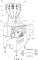
- a bagmaking and packaging apparatus 102 pertaining to an embodiment of the present invention and a weighing, bagmaking, and packaging system 100 including the bagmaking and packaging apparatus 102 will be described below with reference to the drawings.
- FIG. 1 shows an external perspective view of the weighing, bagmaking, and packaging system 100.
- the weighing, bagmaking, and packaging system 100 is a system comprising a weighing apparatus 101 and the bagmaking and packaging apparatus 102.
- the weighing, bagmaking, and packaging system 100 has a configuration where the bagmaking and packaging apparatus 102 is disposed on bottom and the weighing apparatus 101 is disposed on top, and a touch panel 111 and operation switches 112 with which the bagmaking and packaging apparatus 102 and the weighing apparatus 101 can be integrally operated are provided on the right side.
- the weighing apparatus 101 is a combination weigher with a known configuration.
- Articles that are the object of packaging by the bagmaking and packaging apparatus 102 are a snack food such as potato chips, for example, and they are supplied to the central upper portion of the weighing apparatus 101.
- the articles supplied to the central upper portion are dispersed to plural radial paths and are thereafter supplied via plural pool hoppers 24 disposed on terminal ends of the paths to corresponding weigh hoppers 25 below.
- the weights of the articles weighed by the weigh hoppers 25 are combined, and an optimum combination of the weigh hoppers 25 forming a fixed weight of the articles is selected.
- the selected weigh hoppers 25 discharge the articles to a collection chute 26 based on a discharge request signal from the bagmaking and packaging apparatus 102.
- the discharged articles form long columns while falling down the collection chute 26, pass through a funnel member 11 of the bagmaking and packaging apparatus 102, and fall to the inside space of a tube 12.
- the group of articles fall through the inside space of the tube 12 as packaging articles C.
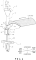
- the bagmaking and packaging apparatus 102 performs bagmaking by putting the packaging articles C inside a tubular film TF and transversely sealing the lower end portion of the tubular film TF and the upper end portion of a preceding bag B at the same time (see FIG. 2 ).
- the bagmaking and packaging apparatus 102 is configured by a packaging unit 5 that packs the packaging articles C that are articles in bags to make products, a film supply unit 6 that supplies a film F to the packaging unit 5, and a control unit 110 (see FIG. 5A ) that controls operations of drive units of the units 5, 6.
- the film supply unit 6 is a unit that supplies the sheet-like film F to a forming mechanism 13 of the packaging unit 5, and is provided adjacent to the rear side of the packaging unit 5.
- the film F is a film F1 paid out from a first film roll FR1 described later or a film F2 paid out from a second film roll FR2. When it is not necessary to distinguish between these, they will simply be called the film F.
- the packaging unit 5 is a unit that makes bags B containing the packaging articles C.
- the packaging unit 5 includes a forming mechanism 13 that forms the sheet-like film F into the tubular film TF, pull-down belt mechanisms 14 that convey downward the film formed in the tubular shape (the tubular film TF), a longitudinal sealing mechanism 15 that longitudinally seals, on the front side, an overlapping portion TF-1 where both edges of the tubular film TF overlap, and a transverse sealing mechanism 17.
- the transverse sealing mechanism 17 transversely seals the bags B formed by the tubular film TF and heat-seals the upper end portion of a bag B and the lower end portion of a trailing bag (the tubular film TF) at the same time.
- the packaging unit 5 has a tube 12 that guides the packaging articles C into the tubular film TF while the tubular film F becomes wrapped around the outer periphery thereof.
- the forming mechanism 13 comprises the tube 12 and a former 13a disposed surrounding the lower portion of the tube 12.
- the sheet-like film F which is paid out from the film roll FR1 or FR2 retained in the film supply unit 6, becomes formed in a tubular shape when it passes through a gap between the former 13a and the tube 12, with the top surface of the film F becoming the inner peripheral surface of the tubular film TF and the bottom surface of the film F becoming the outer peripheral surface of the tubular film TF.
- the pull-down belt mechanisms 14, which have a pair of belts 14c disposed on both left and right sides of the tube 12, are mechanisms that suck hold of and convey downward the tubular film TF wrapped around the tube 12.
- the pull-down belt mechanisms 14, together with the film supply unit 6, function as a conveyance unit that conveys the film F.
- the longitudinal sealing mechanism 15 applies heat to and seals, while pressing with a fixed pressure against the tube 12, the overlapping portion TF-1 where both edges of the tubular film TF overlap.
- the longitudinal sealing mechanism 15 is configured by a heater block and a metal belt that travels, synchronously with the tubular film TF, around the heater block.
- the transverse sealing mechanism 17 transversely seals the tubular film TF, in a state in which the packaging articles C have fallen through the tube 12 into the tubular film TF, to form the bags B filled with the packaging articles C.
- the transverse sealing mechanism 17 is configured by a pair of sealing jaws 51, which have built-in heaters, and drive mechanisms (not shown in the drawings), which move the pair of sealing jaws 51 toward and away from each other relative to the tubular film TF.
- the film supply unit 6 mainly includes a first retention unit 81, a second retention unit 82, plural rollers 91a, 91b, 91c, 92a, 92b, 92c, 93a to 93o, roll drive motors 61, 62, and a film switching unit 63.
- the first retention unit 81 is an air chuck that retains a first film roll FR1 in which a first film F1 is wound.
- the second retention unit 82 is an air chuck that retains a second film roll FR2 in which a second film F2 is wound.
- the first retention unit 81 and the second retention unit 82 are rotated by the roll drive motors 61, 62, respectively.
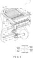
- the distal end of the second retention unit 82 has a guide such as shown in FIG. 3 to facilitate setting of the second film roll FR2 (insertion onto the second retention unit 82) from the rear.
- the distal end of the first retention unit 81 which is positioned more forward than the second retention unit 82, has no guide with a shape such as the one on the distal end of the second retention unit 82.
- the distal end of the first retention unit 81 extends longer leftward than the distal end of the second retention unit 82. For this reason, the first film roll FR1 can be inserted from the left side onto the first retention unit 81.
- the distal end of the first retention unit 81 is rounded, so it is easy to insert the first film roll FR1 onto it, and it is also less likely for the first film roll FR1 at the time of insertion to interfere with the second film F2.
- the plural rollers 91a, 91b, 91c, 92a, 92b, 92c, 93a to 93o are rollers that guide the film F paid out from either film roll FR1 (FR2) and, together with the roll drive motors 61, 62 and the pull-down belt mechanisms 14, function as a conveyance unit that conveys the film F.
- the first film F1 paid out from the first film roll FR1 is guided by the rollers 91a, 91b, 91c and is further guided by the rollers from the roller 93a on.
- the second film F2 paid out from the second film roll FR2 is guided by the rollers 92a, 92b, 92c and is further guided by the rollers from the roller 93a on.
- the film switching unit 63 has a first impulse sealer 64a and a second impulse sealer 64b, a cutter 68, and an air cylinder 66 that are housed inside a case.
- Both impulse sealers 64a, 64b extend in a direction intersecting a film conveyance direction A2 shown in FIG. 8B .
- both impulse sealers 64a, 64b extend in the left and right direction.
- the first impulse sealer 64a and the second impulse sealer 64b are disposed a predetermined distance apart from each other in the film conveyance direction A2.
- the cutter 68 is positioned between the first impulse sealer 64a and the second impulse sealer 64b in the film conveyance direction A2.
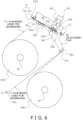
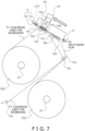
- Both impulse sealers 64a, 64b and the cutter 68 are integrated and are together moved by the air cylinder 66. Furthermore, the film switching unit 63 is supported by a left and right pair of support bases 63a, 63b, and as shown in FIG. 3 is moved in a front and rear direction A1 by an air cylinder 69 different from the air cylinder 66. Specifically, movement of the film switching unit 63 from a rear end position shown in FIG. 6 to a front end position shown in FIG. 7 and movement of the film switching unit 63 from the front end position to the rear end position are done by control of the air cylinder 69 by the control unit 110.
- the film supply unit 6 includes a seal table 65a, which opposes both impulse sealers 64a, 64b of the film switching unit 63 in the front end position across the film conveyance path, and a seal table 65b, which opposes the impulse sealers 64a, 64b of the film switching unit 63 in the rear end position across the film conveyance path (see FIG. 6 and FIG. 7 ).
- the seal table 65a is positioned between the rollers 91a, 91b.
- the seal table 65b is positioned between the rollers 92b, 92c.
- the seal tables 65a, 65b have the same configurations, so here the seal table 65a will be taken as an example and described. As shown in FIG.
- the seal table 65a is divided into a first portion 65a1 that opposes the first impulse sealer 64a in the front end position and a second portion 65a2 that opposes the second impulse sealer 64b in the front end position.
- the space between the first portion 65a1 and the second portion 65a2 of the seal table 65a is a space into and from which the distal end of the cutter 68 enters and exits.
- the film switching unit 63 interconnects and cuts the first film F1 and the second film F2 that vertically overlap each other on the film conveyance path.
- the air cylinder 66 operates and the cutter 68 and both impulse sealers 64a, 64b move toward the seal table 65a.
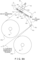
- the first film F1 and the second film F2 are cut in a position between the roller 91a and the roller 91b, and immediately thereafter the first film F1 and the second film F2 are pinched between the impulse sealers 64a, 64b and the seal table 65a and heat-sealed.
- the first film F1 and the second film F2 are heat-sealed and interconnected in a first position between the first impulse sealer 64a and the first portion 65a1 shown in FIG. 8B
- the first film F1 and the second film F2 are heat-sealed and interconnected in a second position between the second impulse sealer 64b and the second portion 65a2.
- the cutter 68 cuts the first film F1 and the second film F2 in a position between the first position and the second position.
- the cutting is performed first and the heat-sealing is performed thereafter, the cutting and the heat-sealing may be performed at the same time, or the cutting may be performed after the heat-sealing.
- This cutting and heat-sealing (interconnection) of the overlapping portion of the first film F1 and the second film F2 by the cutter 68 and both impulse sealers 64a, 64b of the film switching unit 63 is, as described later, performed when switching from bagmaking and packaging using the first film F1 to bagmaking and packaging using the second film F2. Because of this cutting and heat-sealing, as shown in FIG. 8B , the first impulse sealer 64a forms a first interconnected film F1E/F2T and the second impulse sealer 64b forms a second interconnected film F1/F2.
- the first impulse sealer 64a interconnects a first part (an end-of-bagmaking film F1E) on the first retention unit 81 side of the first film F1 and a second part (a starting end scrap F2T) on the starting end side of the second film F2 to form a first interconnected film F1E/F2T that is a film in which the first part and the second part are interconnected.
- the second impulse sealer 64b interconnects a third part on the starting end side of the first film F1 and a fourth part on the second retention unit 82 side of the second film F2 to form a second interconnected film F1/F2 that is a film in which the third part and the fourth part are interconnected.
- the first film F1 is cut between the first part and the third part by the cutter 68, and the second film F2 is also cut between the second part and the fourth part by the cutter 68, so the first interconnected film F1E/F2T and the second interconnected film F1/F2 become separate films.
- the film switching unit 63 further includes a first gripping unit 71, which restrains the starting end of the second film F2, and a second gripping unit 72, which restrains the starting end of the first film F1.
- the first gripping unit 71 and the second gripping unit 72 have the same structures, so here the first gripping unit 71 will be described.
- the first gripping unit 71 has a restraining member 71a, which includes an L-shaped member extending in the left and right direction, and a base 71b, which extends in the left and right direction.
- the restraining member 71a is manually switchable between a state in which it is away from the base 71b (see FIG.
- the control unit 110 individually or integrally controls the weighing apparatus 101 and the bagmaking and packaging apparatus 102 and is realized by a computer.
- the control unit 110 includes a control arithmetic unit and a storage unit.
- a processor such as a CPU or a GPU can be used.
- the control arithmetic unit reads programs stored in the storage unit and performs predetermined image processing and arithmetic processing in accordance with the programs.
- the control arithmetic unit can write arithmetic results in the storage unit and read information stored in the storage unit in accordance with the programs.
- the control unit 110 controls the drive units of the packaging unit 5 and the film supply unit 6 in accordance with parameters set using the touch panel 111 or the like and operating conditions.
- the control unit 110 also controls feeders, the pool hoppers 24, and the weigh hoppers 25 of the weighing apparatus 101. Specifically, the control unit 110 imports necessary information from various sensors installed in the weighing apparatus 101 and the bagmaking and packaging apparatus 102 and performs various types of control based on that information.
- setting of the second film roll FR2 by the operator is performed.
- the setting of the second film roll FR2 is manually performed by the operator.
- the operator inserts the second retention unit 82 through a central opening in the second film roll FR2 and thereafter manually pays out the starting end F2T of the second film F2 shown in FIG. 6 .
- the operator passes the starting end F2T of the second film F2 around the roller 92a, passes it over the rollers 92b, 92c, and brings it to the first gripping unit 71 through the space above the rollers 91b, 91a that are currently conveying the first film F1.
- the operator passes the starting end F2T of the second film F2 between the restraining member 71a and the base 71b and lowers the restraining member 71a to thereby cause the first gripping unit 71 to grip the starting end F2T of the second film F2.
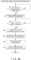
- the control unit 110 determines in step S11 shown in FIG. 5B whether the setting of the second film roll FR2 has been completed. This determination is made based on whether the operator who has finished setting the second film roll FR2 has pushed a "Done" button using the touch panel 111.
- step S12 the control unit 110 moves the film switching unit 63 from the rear end position shown in FIG. 6 to the front end position shown in FIG. 7 .
- step S13 determines in step S13 whether there is no more of the first film F1 of the first film roll FR1 left. This determination is performed based on detection of the roll drive motor 61 by an encoder.
- step S14 it temporarily stops bagmaking and packaging. Specifically, the control unit 110 stops film conveyance by stopping the roll drive motor 61 and the pull-down belt mechanisms 14 and also stops driving each part of the packaging unit 5. Thereafter, in step S15 the control unit 110 cuts and heat-seals, with the cutter 68 and both impulse sealers 64a, 64b, the first film F1 and the second film F2 that are stopped in an overlapped state between the roller 91a and the roller 91b. This cutting and heat-sealing is performed as described above as shown in FIG. 8A and FIG. 8B . Thereafter, as shown in FIG.
- step S16 the control unit 110 uses the air cylinder 66 to retract the cutter 68 and both impulse sealers 64a, 64b to separate the cutter 68 and both impulse sealers 64a, 64b from the seal table 65a. Because of this, as shown in FIG. 10 , a heat-sealed part SP in the first interconnected film F1E/F2T comes out from the space between the film switching unit 63 and the seal table 65a.
- step S17 the control unit 110 resumes bagmaking and packaging using the second interconnected film F1/F2 and the trailing second film F2, the operator manually releases the first gripping unit 71 and detaches and removes from the first retention unit 81 the first film roll FR1 that has run out of the first film F1. Because of this, as shown in FIG. 11 , there is no longer the first film roll FR1 attached to the first retention unit 81. In the state shown in FIG. 11 also, the control unit 110 continues bagmaking and packaging operations using the second film F2.
- step S17 of FIG. 5B control that comes after step S17 of FIG. 5B will be described with reference to FIG. 5C and FIG. 11 to FIG. 16 .
- the control unit 110 determines in step S21 whether setting of the first film roll FR1 has been completed.
- the setting of the first film roll FR1 by the operator from the state shown in FIG. 11 has been completed, as shown in FIG. 12 the starting end F1T of the first film F1 becomes gripped by the second gripping unit 72 in a state in which the second film F2 that is currently being conveyed and the first film F1 that is on standby vertically overlap each other above the rollers 92b, 92c.
- the control unit 110 determines that the setting of the first film roll FR1 has been completed, in step S22 it moves the film switching unit 63 from the front end position shown in FIG. 12 to the rear end position shown in FIG. 13 .
- control unit 110 determines in step S23 whether there is no more of the second film F2 of the second film roll FR2 left. This determination is performed based on detection of the roll drive motor 62 by an encoder.
- control unit 110 determines that there is no more of the second film F2 of the second film roll FR2 left, in step S24 it temporarily stops bagmaking and packaging.
- the control unit 110 cuts and heat-seals, with the cutter 68 and both impulse sealers 64a, 64b, the second film F2 and the first film F1 that are stopped in an overlapped state between the roller 92b and the roller 92c (see FIG. 14 ). Thereafter, as shown in FIG.
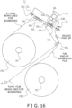
- step S26 the control unit 110 uses the air cylinder 66 to retract the cutter 68 and both impulse sealers 64a, 64b to separate the cutter 68 and both impulse sealers 64a, 64b from the seal table 65b. Because of this, as shown in FIG. 16 , the heat-sealed part SP comes out from the space between the film switching unit 63 and the seal table 65b.
- step S27 the control unit 110 resumes bagmaking and packaging using the interconnected film F2/F1 and the trailing first film F1, the operator manually detaches and removes from the second retention unit 82 the second film roll FR2 that has run out of the second film F2.
- the film switching unit 63 forms the second interconnected film F1/F2 that becomes used for bagmaking and packaging and interconnects the second part (the starting end scrap F2T of FIG. 8B ) on the starting end side of the second film F2 and the first part (the end-of-bagmaking film F1E of FIG. 8B ) on the first retention unit 81 side of the first film F1 to form the first interconnected film F1E/F2T.
- the second part on the starting end side of the second film F2 is connected to the first part on the first retention unit 81 side of the first film F1 without becoming a scrap of the second film F2. Because of this, in the bagmaking and packaging apparatus 102, the second part (the starting end scrap F2T of FIG. 8B ) on the starting end side of the second film F2 no longer becomes a scrap of the second film F2, and the burden on the operator of having to remove the scrap of the second film F2 by hand is reduced.
- This characteristic is also the same when switching from bagmaking and packaging using the second film F2 to bagmaking and packaging using the first film F1.
- the bagmaking and packaging apparatus 102 includes the air cylinder 69 that moves the film switching unit 63, and the control unit 110 moves the film switching unit 63 when switching from bagmaking and packaging using the first film F1 to bagmaking and packaging using the second film F2.
- the control unit 110 also moves the film switching unit 63 when switching from bagmaking and packaging using the second film F2 to bagmaking and packaging using the first film F1. Because of this, work when replacing by hand the first film roll FR1 or the second film roll FR2 that has run out of film with a new one becomes easier.
- the control unit 110 controls the air cylinder 69 so that the position of the film switching unit 63 when switching from bagmaking and packaging using the first film F1 to bagmaking and packaging using the second film F2 and the position of the film switching unit 63 when switching from bagmaking and packaging using the second film F2 to bagmaking and packaging using the first film F1 are different. Because of this, work when replacing by hand the first film roll FR1 or the second film roll FR2 that has run out of film with a new one becomes simple.
- impulse sealers 64a, 64b instead of the impulse sealers 64a, 64b, other sealers such as hot plate sealers, ultrasonic sealers, and high-frequency sealers may be employed.
- the control unit 110 may be configured to change the output of the impulse sealers 64a, 64b based on film information such as the winding direction (front side facing out, back side facing out) of the film F1 (F2) and whether the films are for being overlapped or for being pinch-sealed. Because of this, the impulse sealers 64a, 64b are adjusted to appropriate sealing temperatures and appropriate sealing durations.
- control unit 110 changes the duration of the heat-sealing of the first film F1 and the second film F2 depending on whether contact surfaces of the first film F1 and the second film F2 that overlap each other are front sides of the films or back sides of the films.
- control unit 110 may automatically perform, or the operator may perform, a predetermined operation so that the first retention unit 81 is rotated just a little by the roll drive motor 61 to take up the first interconnected film F1E/F2T on the first film roll FR1.
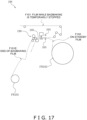
- the film supply unit 106 has a first retention unit that retains a first film roll FR101, a second retention unit that retains a second film roll FR102, a conveyance unit that includes plural rollers 190 and a film conveyance mechanism, one pair of a sealer 164 and a table 165, and a cutter 168.
- the conveyance unit conveys the first film F 101 and the second film F102 in a film conveyance direction.
- the sealer 164 extends in a direction orthogonal to the film conveyance direction.
- illustration of rollers not necessary for the following description of operations is omitted.
- the sealer 164 again descends and the first film F101 and the second film F 102 are heat-sealed.
- This interconnected point SP2 moves leftward in the drawing beyond the space under the cutter 168 as a result of the conveyance unit thereafter conveying the first film F 101 and the second film F102 in the opposite direction.
- the first interconnected point SP1 first position
- the second interconnected point SP2 second position
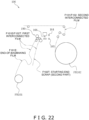
- the cutter 168 descends, the first film F 101 and the second film F 102 are cut in a position between the first interconnected point SP1 and the second interconnected point SP2. That is, the cutter 168 functioning as a cutting unit cuts the first film F 101 and the second film F 102 in a position between the first position and the second position. Because of this, in the bagmaking and packaging apparatus of this example modification, when switching from bagmaking using the first film F 101 to bagmaking using the second film F 102, as shown in FIG. 22 , a first interconnected film F101E/F102T is formed and a second interconnected film F101/F102 is formed.
- the sealer 164 of the bagmaking and packaging apparatus interconnects a first part F101E on the first retention unit side of the first film F101 and a second part F102T on the starting end side of the second film F 102 to form a first interconnected film F101E/F102T that is a film in which the first part F101E and the second part F102T are interconnected. Furthermore, the sealer 164 of the bagmaking and packaging apparatus interconnects a third part on the starting end side of the first film F101 and a fourth part on the second retention unit side of the second film F102 to form a second interconnected film F101/F102 that is a film in which the third part and the fourth part are interconnected.
- Patent Document 1 JP-A No. 2008-1429
Landscapes
- Engineering & Computer Science (AREA)
- Mechanical Engineering (AREA)
- Replacement Of Web Rolls (AREA)
- Containers And Plastic Fillers For Packaging (AREA)
- Auxiliary Devices For And Details Of Packaging Control (AREA)
- Bag Frames (AREA)
Abstract
In a bagmaking and packaging apparatus, when switching from bagmaking using a first film F1 to bagmaking using a second film F2, a first impulse sealer 64a interconnects an end-of-bagmaking film F1E of the first film F1 and a starting end scrap F2T of the second film F2 to form a first interconnected film F1E/F2T. A second impulse sealer 64b interconnects a third part on a starting end side of the first film F1 and a fourth part of the second film F2 to form a second interconnected film F1/F2.
Description
- The present invention relates to a bagmaking and packaging apparatus.
- Conventionally, in relation to bagmaking and packaging apparatus that use a film to automatically package articles, technologies are known which shorten the amount of time in which the apparatus is stopped and switch between film rolls by presetting a film roll separate from a film roll currently in use and automatically connect the starting end part of the separate film roll when the film of the film roll has run low. For example, Patent Document 1 (
JP-A No. 2008-1429 - In conventional packaging apparatus such as disclosed in
Patent Document 1, two films are automatically interconnected, the interconnected part is cut by a cutter, and thereafter bagmaking and packaging using the film paid out from the new film roll is performed. - However, when two films are interconnected and the interconnected part is cut, the starting end part of the new film ends up being left over as a film scrap, and the film scrap needs to be removed by human hands. This is because if the film scrap is not removed, the scrap may get caught in a film conveyance mechanism or entangled in a drive mechanism of the packaging apparatus and obstruct the operation of the packaging apparatus.
- It is a problem of the present invention to inhibit a film scrap from being generated when interconnecting two films in a bagmaking and packaging apparatus and reduce the burden on an operator of having to remove the film scrap by hand.
- A bagmaking and packaging apparatus of a first aspect includes a first retention unit, a second retention unit, a conveyance unit, a bagmaking and packaging unit, an interconnecting unit, and a cutting unit. The first retention unit retains a first film roll in which a film is wound. The second retention unit retains a second film roll in which a film is wound. The conveyance unit conveys a film in a film conveyance direction. The bagmaking and packaging unit makes bags containing articles using the film conveyed by the conveyance unit. The interconnecting unit has a splicing unit. The splicing unit extends in a direction intersecting the film conveyance direction. The interconnecting unit uses the splicing unit to interconnect a first film and a second film in a first position and a second position. The first position and the second position are positions where the first film and the second film overlap each other. The first film is the film pulled out from the first film roll. The second film is the film pulled out from the second film roll. The cutting unit cuts the first film and the second film in a position between the first position and the second position. In the bagmaking and packaging apparatus, when switching from bagmaking using the first film to bagmaking using the second film, the splicing unit forms a first interconnected film and forms a second interconnected film. Specifically, the splicing unit interconnects a first part on the first retention unit side of the first film and a second part on a starting end side of the second film to form a first interconnected film that is a film in which the first part and the second part are interconnected. The splicing unit interconnects a third part on a starting end side of the first film and a fourth part on the second retention unit side of the second film to form a second interconnected film that is a film in which the third part and the fourth part are interconnected.
- Here, when switching from bagmaking using the first film to bagmaking using the second film, the splicing unit forms the second interconnected film that becomes used for bagmaking and packaging and connects the second part on the starting end side of the second film to the first part on the first retention unit side of the first film to form the first interconnected film. For this reason, the second part on the starting end side of the second film is connected to the first part on the first retention unit side of the first film without becoming a film scrap. Because of this, in the bagmaking and packaging apparatus of the first aspect, the second part on the starting end side of the second film is inhibited from becoming a film scrap, and the burden on the operator of having to remove the film scrap by hand is reduced.
- It will be noted that the cutting of the first film and the second film by the cutting unit may be performed before the first film and the second film are interconnected or may be performed after the first film and the second film are interconnected.
- A bagmaking and packaging apparatus of a second aspect is the bagmaking and packaging apparatus of the first aspect, wherein the splicing unit has a first sealing unit and a second sealing unit. The first sealing unit and the second sealing unit extend in a direction intersecting the film conveyance direction. The first sealing unit and the second sealing unit are disposed a predetermined distance apart from each other in the film conveyance direction. The first sealing unit interconnects the first film and the second film in the first position. The second sealing unit interconnects the first film and the second film in the second position. When switching from bagmaking using the first film to bagmaking using the second film, the first sealing unit interconnects the first part and the second part to form the first interconnected film and the second sealing unit interconnects the third part and the fourth part to form the second interconnected film.
- A bagmaking and packaging apparatus of a third aspect is the bagmaking and packaging apparatus of the first aspect or the second aspect, wherein the cutting unit cuts the first film between the first part and the third part and the second film between the second part and the fourth part.
- A bagmaking and packaging apparatus of a fourth aspect is the bagmaking and packaging apparatus of the third aspect, wherein the apparatus switches from bagmaking using the first film to bagmaking using the second interconnected film and furthermore switches from bagmaking using the second interconnected film to bagmaking using the second film after the formation of the first interconnected film, the formation of the second interconnected film, and the cutting of the first film and the second film.
- A bagmaking and packaging apparatus of a fifth aspect is the bagmaking and packaging apparatus of any of the first aspect to the fourth aspect, further including a control unit that controls the interconnecting unit. The splicing unit heat-seals the first film and the second film. The control unit changes the duration of the heat-sealing of the first film and the second film depending on whether contact surfaces of the first film and the second film that overlap each other are front sides of the films or back sides of the films.
- A bagmaking and packaging apparatus of a sixth aspect is the bagmaking and packaging apparatus of any of the first aspect to the fifth aspect, further including a moving unit that moves the interconnecting unit. The moving unit moves the interconnecting unit when switching from bagmaking using the first film to bagmaking using the second film.
- A bagmaking and packaging apparatus of a seventh aspect is the bagmaking and packaging apparatus of the sixth aspect, further including a control unit that controls the moving unit. The control unit controls the moving unit so that the position of the interconnecting unit when switching from bagmaking using the first film to bagmaking using the second film and the position of the interconnecting unit when switching from bagmaking using the second film to bagmaking using the first film are different.
- A bagmaking and packaging apparatus of an eighth aspect is the bagmaking and packaging apparatus of the first aspect, wherein the conveyance unit conveys the first film and the second film after the interconnection of the first film and the second film by the splicing unit in the first position and before the interconnection of the first film and the second film by the splicing unit in the second position.
- A bagmaking and packaging apparatus of a ninth aspect is the bagmaking and packaging apparatus of the eighth aspect, wherein the cutting unit cuts the first film and the second film in a position between the first position and the second position after the interconnection of the first film and the second film by the splicing unit in the second position.
- A bagmaking and packaging apparatus of a tenth aspect is the bagmaking and packaging apparatus of the ninth aspect, wherein the conveyance unit conveys the first film and the second film to match the position of the cutting of the first film and the second film by the cutting unit after the interconnection of the first film and the second film by the splicing unit in the second position and before the cutting of the first film and the second film by the cutting unit.
- According to the bagmaking and packaging apparatus pertaining to the present invention, the second part on the starting end side of the second film is connected to the first part on the first retention unit side of the first film without becoming a film scrap. Because of this, in the bagmaking and packaging apparatus of the present invention, the second part on the starting end side of the second film is inhibited from becoming a film scrap, and the burden on the operator of having to remove the film scrap by hand is reduced.
-
-
FIG. 1 is an external view, seen from the front right side, of a weighing, bagmaking, and packaging system including a bagmaking and packaging apparatus; -
FIG. 2 is a schematic perspective view showing main configurations of a bagmaking and packaging unit of the bagmaking and packaging apparatus; -
FIG. 3 is an external view, seen from the rear side, of a film supply unit of the bagmaking and packaging apparatus; -
FIG. 4 is a drawing showing a film moving path in which the film supply unit is seen from the right side; -
FIG. 5A is a control block diagram of the weighing, bagmaking, and packaging system; -
FIG. 5B is a film switching control flowchart; -
FIG. 5C is a film switching control flowchart; -
FIG. 6 is a drawing showing a state of the film supply unit before connecting a second film; -
FIG. 7 is a drawing showing a state of the film supply unit before connecting the second film; -
FIG. 8A is a drawing showing a state of the film supply unit when connecting the second film; -
FIG. 8B is a partially enlarged view ofFIG. 8A ; -
FIG. 9 is a drawing showing a state of the film supply unit after connecting the second film; -
FIG. 10 is a drawing showing a state of the film supply unit after connecting the second film; -
FIG. 11 is a drawing showing a state of the film supply unit from which a first film roll has been detached; -
FIG. 12 is a drawing showing a state of the film supply unit to which the first film roll has been attached; -
FIG. 13 is a drawing showing a state of the film supply unit before connecting a first film; -
FIG. 14 is a drawing showing a state of the film supply unit when connecting the first film; -
FIG. 15 is a drawing showing a state of the film supply unit after connecting the first film; -
FIG. 16 is a drawing showing a state of the film supply unit when detaching the second film roll; -
FIG. 17 is a drawing showing a state of a film supply unit of an example modification before connecting a second film; -
FIG. 18 is a drawing showing a state of the film supply unit of the example modification when connecting the second film; -
FIG. 19 is a drawing showing a state of the film supply unit of the example modification after connecting the second film; -
FIG. 20 is a drawing showing a state of the film supply unit of the example modification after connecting the second film; -
FIG. 21 is a drawing showing a state of the film supply unit of the example modification after connecting the second film; and -
FIG. 22 is a drawing showing a state of the film supply unit of the example modification after connecting the second film. - An embodiment of the present invention will be described below with reference to the drawings. It will be noted that the following embodiment is one specific example of the present invention and is not intended to limit the technical scope of the present invention.
- A bagmaking and
packaging apparatus 102 pertaining to an embodiment of the present invention and a weighing, bagmaking, andpackaging system 100 including the bagmaking andpackaging apparatus 102 will be described below with reference to the drawings. -
FIG. 1 shows an external perspective view of the weighing, bagmaking, andpackaging system 100. The weighing, bagmaking, andpackaging system 100 is a system comprising a weighingapparatus 101 and the bagmaking andpackaging apparatus 102. The weighing, bagmaking, andpackaging system 100 has a configuration where the bagmaking andpackaging apparatus 102 is disposed on bottom and the weighingapparatus 101 is disposed on top, and atouch panel 111 and operation switches 112 with which the bagmaking andpackaging apparatus 102 and the weighingapparatus 101 can be integrally operated are provided on the right side. - The weighing
apparatus 101 is a combination weigher with a known configuration. Articles that are the object of packaging by the bagmaking andpackaging apparatus 102 are a snack food such as potato chips, for example, and they are supplied to the central upper portion of the weighingapparatus 101. The articles supplied to the central upper portion are dispersed to plural radial paths and are thereafter supplied viaplural pool hoppers 24 disposed on terminal ends of the paths to correspondingweigh hoppers 25 below. The weights of the articles weighed by theweigh hoppers 25 are combined, and an optimum combination of theweigh hoppers 25 forming a fixed weight of the articles is selected. The selectedweigh hoppers 25 discharge the articles to acollection chute 26 based on a discharge request signal from the bagmaking andpackaging apparatus 102. The discharged articles form long columns while falling down thecollection chute 26, pass through afunnel member 11 of the bagmaking andpackaging apparatus 102, and fall to the inside space of atube 12. The group of articles fall through the inside space of thetube 12 as packaging articles C. The bagmaking andpackaging apparatus 102 performs bagmaking by putting the packaging articles C inside a tubular film TF and transversely sealing the lower end portion of the tubular film TF and the upper end portion of a preceding bag B at the same time (seeFIG. 2 ). - The bagmaking and
packaging apparatus 102 is configured by apackaging unit 5 that packs the packaging articles C that are articles in bags to make products, afilm supply unit 6 that supplies a film F to thepackaging unit 5, and a control unit 110 (seeFIG. 5A ) that controls operations of drive units of theunits film supply unit 6 is a unit that supplies the sheet-like film F to a formingmechanism 13 of thepackaging unit 5, and is provided adjacent to the rear side of thepackaging unit 5. - It will be noted that the film F is a film F1 paid out from a first film roll FR1 described later or a film F2 paid out from a second film roll FR2. When it is not necessary to distinguish between these, they will simply be called the film F.
- The
packaging unit 5 is a unit that makes bags B containing the packaging articles C. As shown inFIG. 2 , thepackaging unit 5 includes a formingmechanism 13 that forms the sheet-like film F into the tubular film TF, pull-downbelt mechanisms 14 that convey downward the film formed in the tubular shape (the tubular film TF), alongitudinal sealing mechanism 15 that longitudinally seals, on the front side, an overlapping portion TF-1 where both edges of the tubular film TF overlap, and atransverse sealing mechanism 17. Thetransverse sealing mechanism 17 transversely seals the bags B formed by the tubular film TF and heat-seals the upper end portion of a bag B and the lower end portion of a trailing bag (the tubular film TF) at the same time. Furthermore, thepackaging unit 5 has atube 12 that guides the packaging articles C into the tubular film TF while the tubular film F becomes wrapped around the outer periphery thereof. - The forming
mechanism 13 comprises thetube 12 and a former 13a disposed surrounding the lower portion of thetube 12. The sheet-like film F, which is paid out from the film roll FR1 or FR2 retained in thefilm supply unit 6, becomes formed in a tubular shape when it passes through a gap between the former 13a and thetube 12, with the top surface of the film F becoming the inner peripheral surface of the tubular film TF and the bottom surface of the film F becoming the outer peripheral surface of the tubular film TF. - The pull-down
belt mechanisms 14, which have a pair ofbelts 14c disposed on both left and right sides of thetube 12, are mechanisms that suck hold of and convey downward the tubular film TF wrapped around thetube 12. The pull-downbelt mechanisms 14, together with thefilm supply unit 6, function as a conveyance unit that conveys the film F. - The
longitudinal sealing mechanism 15 applies heat to and seals, while pressing with a fixed pressure against thetube 12, the overlapping portion TF-1 where both edges of the tubular film TF overlap. Thelongitudinal sealing mechanism 15 is configured by a heater block and a metal belt that travels, synchronously with the tubular film TF, around the heater block. - The
transverse sealing mechanism 17 transversely seals the tubular film TF, in a state in which the packaging articles C have fallen through thetube 12 into the tubular film TF, to form the bags B filled with the packaging articles C. Thetransverse sealing mechanism 17 is configured by a pair of sealingjaws 51, which have built-in heaters, and drive mechanisms (not shown in the drawings), which move the pair of sealingjaws 51 toward and away from each other relative to the tubular film TF. - As shown in
FIG. 3 ,FIG. 4 ,FIG. 5A , andFIG. 6 , thefilm supply unit 6 mainly includes afirst retention unit 81, asecond retention unit 82,plural rollers drive motors film switching unit 63. - The
first retention unit 81 is an air chuck that retains a first film roll FR1 in which a first film F1 is wound. Thesecond retention unit 82 is an air chuck that retains a second film roll FR2 in which a second film F2 is wound. Thefirst retention unit 81 and thesecond retention unit 82 are rotated by theroll drive motors - It will be noted that as shown in
FIG. 3 the distal end of thesecond retention unit 82 has a guide such as shown inFIG. 3 to facilitate setting of the second film roll FR2 (insertion onto the second retention unit 82) from the rear. In contrast, the distal end of thefirst retention unit 81, which is positioned more forward than thesecond retention unit 82, has no guide with a shape such as the one on the distal end of thesecond retention unit 82. Instead, the distal end of thefirst retention unit 81 extends longer leftward than the distal end of thesecond retention unit 82. For this reason, the first film roll FR1 can be inserted from the left side onto thefirst retention unit 81. Furthermore, the distal end of thefirst retention unit 81 is rounded, so it is easy to insert the first film roll FR1 onto it, and it is also less likely for the first film roll FR1 at the time of insertion to interfere with the second film F2. - The
plural rollers roll drive motors belt mechanisms 14, function as a conveyance unit that conveys the film F. As shown inFIG. 6 , the first film F1 paid out from the first film roll FR1 is guided by therollers roller 93a on. As shown inFIG. 13 , the second film F2 paid out from the second film roll FR2 is guided by therollers roller 93a on. - The
film switching unit 63 has afirst impulse sealer 64a and asecond impulse sealer 64b, acutter 68, and anair cylinder 66 that are housed inside a case. Bothimpulse sealers FIG. 8B . Specifically, bothimpulse sealers first impulse sealer 64a and thesecond impulse sealer 64b are disposed a predetermined distance apart from each other in the film conveyance direction A2. Thecutter 68 is positioned between thefirst impulse sealer 64a and thesecond impulse sealer 64b in the film conveyance direction A2. Bothimpulse sealers cutter 68 are integrated and are together moved by theair cylinder 66. Furthermore, thefilm switching unit 63 is supported by a left and right pair ofsupport bases FIG. 3 is moved in a front and rear direction A1 by anair cylinder 69 different from theair cylinder 66. Specifically, movement of thefilm switching unit 63 from a rear end position shown inFIG. 6 to a front end position shown inFIG. 7 and movement of thefilm switching unit 63 from the front end position to the rear end position are done by control of theair cylinder 69 by thecontrol unit 110. - Furthermore, the
film supply unit 6 includes a seal table 65a, which opposes bothimpulse sealers film switching unit 63 in the front end position across the film conveyance path, and a seal table 65b, which opposes theimpulse sealers film switching unit 63 in the rear end position across the film conveyance path (seeFIG. 6 andFIG. 7 ). The seal table 65a is positioned between therollers rollers FIG. 8B , the seal table 65a is divided into a first portion 65a1 that opposes thefirst impulse sealer 64a in the front end position and a second portion 65a2 that opposes thesecond impulse sealer 64b in the front end position. The space between the first portion 65a1 and the second portion 65a2 of the seal table 65a is a space into and from which the distal end of thecutter 68 enters and exits. Thefilm switching unit 63 interconnects and cuts the first film F1 and the second film F2 that vertically overlap each other on the film conveyance path. When there is an instruction to perform the interconnection and cutting from thecontrol unit 110, theair cylinder 66 operates and thecutter 68 and bothimpulse sealers - As shown in
FIG. 8A , when thecontrol unit 110 issues an instruction to extend to theair cylinder 66 of thefilm switching unit 63 in a state in which thecutter 68 and theimpulse sealers cutter 68 and theimpulse sealers roller 91a and theroller 91b, against the seal table 65a. At this time, the first film F1 and the second film F2 are cut in a position between theroller 91a and theroller 91b, and immediately thereafter the first film F1 and the second film F2 are pinched between theimpulse sealers first impulse sealer 64a and the first portion 65a1 shown inFIG. 8B , and the first film F1 and the second film F2 are heat-sealed and interconnected in a second position between thesecond impulse sealer 64b and the second portion 65a2. Thecutter 68 cuts the first film F1 and the second film F2 in a position between the first position and the second position. Here, although the cutting is performed first and the heat-sealing is performed thereafter, the cutting and the heat-sealing may be performed at the same time, or the cutting may be performed after the heat-sealing. - This cutting and heat-sealing (interconnection) of the overlapping portion of the first film F1 and the second film F2 by the
cutter 68 and bothimpulse sealers film switching unit 63 is, as described later, performed when switching from bagmaking and packaging using the first film F1 to bagmaking and packaging using the second film F2. Because of this cutting and heat-sealing, as shown inFIG. 8B , thefirst impulse sealer 64a forms a first interconnected film F1E/F2T and thesecond impulse sealer 64b forms a second interconnected film F1/F2. Specifically, thefirst impulse sealer 64a interconnects a first part (an end-of-bagmaking film F1E) on thefirst retention unit 81 side of the first film F1 and a second part (a starting end scrap F2T) on the starting end side of the second film F2 to form a first interconnected film F1E/F2T that is a film in which the first part and the second part are interconnected. Thesecond impulse sealer 64b interconnects a third part on the starting end side of the first film F1 and a fourth part on thesecond retention unit 82 side of the second film F2 to form a second interconnected film F1/F2 that is a film in which the third part and the fourth part are interconnected. The first film F1 is cut between the first part and the third part by thecutter 68, and the second film F2 is also cut between the second part and the fourth part by thecutter 68, so the first interconnected film F1E/F2T and the second interconnected film F1/F2 become separate films. - The
film switching unit 63 further includes a firstgripping unit 71, which restrains the starting end of the second film F2, and a secondgripping unit 72, which restrains the starting end of the first film F1. The firstgripping unit 71 and the secondgripping unit 72 have the same structures, so here the firstgripping unit 71 will be described. The firstgripping unit 71 has a restrainingmember 71a, which includes an L-shaped member extending in the left and right direction, and abase 71b, which extends in the left and right direction. The restrainingmember 71a is manually switchable between a state in which it is away from thebase 71b (seeFIG. 6 ) and a state in which it is pressed by gravity against thebase 71b and is close to thebase 71b (seeFIG. 7 ). An operator lifts up the restrainingmember 71a so that it is in the state shown inFIG. 6 , passes the starting end F2T of the second film F2 between the restrainingmember 71a and thebase 71b, and lowers the restrainingmember 71a. By so doing, the starting end F2T of the second film F2 becomes gripped by the firstgripping unit 71 as shown inFIG. 7 . - The
control unit 110 individually or integrally controls the weighingapparatus 101 and the bagmaking andpackaging apparatus 102 and is realized by a computer. Thecontrol unit 110 includes a control arithmetic unit and a storage unit. For the control arithmetic unit, a processor such as a CPU or a GPU can be used. The control arithmetic unit reads programs stored in the storage unit and performs predetermined image processing and arithmetic processing in accordance with the programs. Moreover, the control arithmetic unit can write arithmetic results in the storage unit and read information stored in the storage unit in accordance with the programs. - The
control unit 110 controls the drive units of thepackaging unit 5 and thefilm supply unit 6 in accordance with parameters set using thetouch panel 111 or the like and operating conditions. Thecontrol unit 110 also controls feeders, thepool hoppers 24, and theweigh hoppers 25 of the weighingapparatus 101. Specifically, thecontrol unit 110 imports necessary information from various sensors installed in the weighingapparatus 101 and the bagmaking andpackaging apparatus 102 and performs various types of control based on that information. - Semiautomatic switching from bagmaking and packaging using the first film F1 of the first film roll FR1 to bagmaking and packaging using the second film F2 of the second film roll FR2 and semiautomatic switching from bagmaking and packaging using the second film F2 of the second film roll FR2 to bagmaking and packaging using the first film F1 of the first film roll FR1 will now be described with reference to
FIG. 5B andFIG. 5C . - When bagmaking and packaging using the first film F1 of the first film roll FR1 is being performed, setting of the second film roll FR2 by the operator is performed. The setting of the second film roll FR2 is manually performed by the operator. The operator inserts the
second retention unit 82 through a central opening in the second film roll FR2 and thereafter manually pays out the starting end F2T of the second film F2 shown inFIG. 6 . Then, the operator passes the starting end F2T of the second film F2 around theroller 92a, passes it over therollers gripping unit 71 through the space above therollers member 71a and thebase 71b and lowers the restrainingmember 71a to thereby cause the firstgripping unit 71 to grip the starting end F2T of the second film F2. - The
control unit 110 determines in step S11 shown inFIG. 5B whether the setting of the second film roll FR2 has been completed. This determination is made based on whether the operator who has finished setting the second film roll FR2 has pushed a "Done" button using thetouch panel 111. When the setting of the second film roll FR2 has been completed, in step S12 thecontrol unit 110 moves thefilm switching unit 63 from the rear end position shown inFIG. 6 to the front end position shown inFIG. 7 . Next, thecontrol unit 110 determines in step S13 whether there is no more of the first film F1 of the first film roll FR1 left. This determination is performed based on detection of theroll drive motor 61 by an encoder. When thecontrol unit 110 determines that there is no more of the first film F1 of the first film roll FR1 left, in step S14 it temporarily stops bagmaking and packaging. Specifically, thecontrol unit 110 stops film conveyance by stopping theroll drive motor 61 and the pull-downbelt mechanisms 14 and also stops driving each part of thepackaging unit 5. Thereafter, in step S15 thecontrol unit 110 cuts and heat-seals, with thecutter 68 and bothimpulse sealers roller 91a and theroller 91b. This cutting and heat-sealing is performed as described above as shown inFIG. 8A andFIG. 8B . Thereafter, as shown inFIG. 9 , in step S16 thecontrol unit 110 uses theair cylinder 66 to retract thecutter 68 and bothimpulse sealers cutter 68 and bothimpulse sealers FIG. 10 , a heat-sealed part SP in the first interconnected film F1E/F2T comes out from the space between thefilm switching unit 63 and the seal table 65a. When in step S17 thecontrol unit 110 resumes bagmaking and packaging using the second interconnected film F1/F2 and the trailing second film F2, the operator manually releases the firstgripping unit 71 and detaches and removes from thefirst retention unit 81 the first film roll FR1 that has run out of the first film F1. Because of this, as shown inFIG. 11 , there is no longer the first film roll FR1 attached to thefirst retention unit 81. In the state shown inFIG. 11 also, thecontrol unit 110 continues bagmaking and packaging operations using the second film F2. - Next, control that comes after step S17 of
FIG. 5B will be described with reference toFIG. 5C andFIG. 11 toFIG. 16 . - The
control unit 110 determines in step S21 whether setting of the first film roll FR1 has been completed. When the setting of the first film roll FR1 by the operator from the state shown inFIG. 11 has been completed, as shown inFIG. 12 the starting end F1T of the first film F1 becomes gripped by the secondgripping unit 72 in a state in which the second film F2 that is currently being conveyed and the first film F1 that is on standby vertically overlap each other above therollers control unit 110 determines that the setting of the first film roll FR1 has been completed, in step S22 it moves thefilm switching unit 63 from the front end position shown inFIG. 12 to the rear end position shown inFIG. 13 . Next, thecontrol unit 110 determines in step S23 whether there is no more of the second film F2 of the second film roll FR2 left. This determination is performed based on detection of theroll drive motor 62 by an encoder. When thecontrol unit 110 determines that there is no more of the second film F2 of the second film roll FR2 left, in step S24 it temporarily stops bagmaking and packaging. Thereafter, in step S25 thecontrol unit 110 cuts and heat-seals, with thecutter 68 and bothimpulse sealers roller 92b and theroller 92c (seeFIG. 14 ). Thereafter, as shown inFIG. 15 , in step S26 thecontrol unit 110 uses theair cylinder 66 to retract thecutter 68 and bothimpulse sealers cutter 68 and bothimpulse sealers FIG. 16 , the heat-sealed part SP comes out from the space between thefilm switching unit 63 and the seal table 65b. When in step S27 thecontrol unit 110 resumes bagmaking and packaging using the interconnected film F2/F1 and the trailing first film F1, the operator manually detaches and removes from thesecond retention unit 82 the second film roll FR2 that has run out of the second film F2. - (5-1)
In the bagmaking andpackaging apparatus 102, as described in sections (2-2-3) and (4-1) above, when switching from bagmaking and packaging using the first film F1 to bagmaking and packaging using the second film F2, thefilm switching unit 63 forms the second interconnected film F1/F2 that becomes used for bagmaking and packaging and interconnects the second part (the starting end scrap F2T ofFIG. 8B ) on the starting end side of the second film F2 and the first part (the end-of-bagmaking film F1E ofFIG. 8B ) on thefirst retention unit 81 side of the first film F1 to form the first interconnected film F1E/F2T. For this reason, the second part on the starting end side of the second film F2 is connected to the first part on thefirst retention unit 81 side of the first film F1 without becoming a scrap of the second film F2. Because of this, in the bagmaking andpackaging apparatus 102, the second part (the starting end scrap F2T ofFIG. 8B ) on the starting end side of the second film F2 no longer becomes a scrap of the second film F2, and the burden on the operator of having to remove the scrap of the second film F2 by hand is reduced. - This characteristic is also the same when switching from bagmaking and packaging using the second film F2 to bagmaking and packaging using the first film F1.
- (5-2)
The bagmaking andpackaging apparatus 102 includes theair cylinder 69 that moves thefilm switching unit 63, and thecontrol unit 110 moves thefilm switching unit 63 when switching from bagmaking and packaging using the first film F1 to bagmaking and packaging using the second film F2. Thecontrol unit 110 also moves thefilm switching unit 63 when switching from bagmaking and packaging using the second film F2 to bagmaking and packaging using the first film F1. Because of this, work when replacing by hand the first film roll FR1 or the second film roll FR2 that has run out of film with a new one becomes easier. - (5-3)
In the bagmaking andpackaging apparatus 102, thecontrol unit 110 controls theair cylinder 69 so that the position of thefilm switching unit 63 when switching from bagmaking and packaging using the first film F1 to bagmaking and packaging using the second film F2 and the position of thefilm switching unit 63 when switching from bagmaking and packaging using the second film F2 to bagmaking and packaging using the first film F1 are different. Because of this, work when replacing by hand the first film roll FR1 or the second film roll FR2 that has run out of film with a new one becomes simple. - (6-1)
Although in the above embodiment theair cylinders - Furthermore, instead of the
impulse sealers - (6-2)
Although in the above embodiment no distinction is made between the front sides and the back sides of the first film F1 and the second film F2, depending on the material of the films there are cases where the temperature of the sealers suited for heat-sealing differs between the front sides and the back sides. In such cases, thecontrol unit 110 may be configured to change the output of theimpulse sealers impulse sealers - For example, the
control unit 110 changes the duration of the heat-sealing of the first film F1 and the second film F2 depending on whether contact surfaces of the first film F1 and the second film F2 that overlap each other are front sides of the films or back sides of the films. - (6-3)
In the above embodiment, after bagmaking and packaging is resumed using the new second film F2, the operator manually releases the firstgripping unit 71 and detaches and removes from thefirst retention unit 81 the first film roll FR1 that has run out of the first film F1. In this case, it is assumed that the operator detaches the first film roll FR1 without moving thefirst retention unit 81, so that the first interconnected film F1E/F2T including the second part (the starting end scrap F2T) on the starting end side of the second film F2 comes out of the bagmaking andpackaging apparatus 102 with the first film roll FR1. - Instead of this, the
control unit 110 may automatically perform, or the operator may perform, a predetermined operation so that thefirst retention unit 81 is rotated just a little by theroll drive motor 61 to take up the first interconnected film F1E/F2T on the first film roll FR1. - (6-4)
Although in the above embodiment the present invention was described using as an example the bagmaking andpackaging apparatus 102 that uses thefilm supply unit 6 including the twoimpulse sealers film supply unit 106 shown inFIG. 17 to FIG. 22 to interconnect afirst film F 101 and a second film F102 is also a specific example of the present invention. Thefilm supply unit 106 will be described below focusing on parts that are different from thefilm supply unit 6 described above. - The
film supply unit 106 has a first retention unit that retains a first film roll FR101, a second retention unit that retains a second film roll FR102, a conveyance unit that includesplural rollers 190 and a film conveyance mechanism, one pair of asealer 164 and a table 165, and acutter 168. The conveyance unit conveys thefirst film F 101 and the second film F102 in a film conveyance direction. Thesealer 164 extends in a direction orthogonal to the film conveyance direction. Regarding theplural rollers 190, illustration of rollers not necessary for the following description of operations is omitted. - As shown in
FIG. 17 , when there is no more of the film of the first film roll FR101 left, bagmaking is temporarily stopped, and thefirst film F 101 and the second film F102 vertically overlap each other in a stopped state below thesealer 164. In this state, as shown inFIG. 18 , the sealer 64 descends and thefirst film F 101 and thesecond film F 102 are partially heat-sealed (interconnected). Thereafter, the conveyance unit conveys thefirst film F 101 and thesecond film F 102 in a forward direction as shown inFIG. 19 so that an interconnected point SP1 formed by thesealer 164 moves rightward in the drawing. In this state, as shown inFIG. 20 , thesealer 164 again descends and the first film F101 and thesecond film F 102 are heat-sealed. This interconnected point SP2, as shown inFIG. 21 , moves leftward in the drawing beyond the space under thecutter 168 as a result of the conveyance unit thereafter conveying thefirst film F 101 and the second film F102 in the opposite direction. When the conveyance of thefirst film F 101 and thesecond film F 102 in the opposite direction by the conveyance unit ends, the first interconnected point SP1 (first position) becomes positioned on the right side of thecutter 168 and the second interconnected point SP2 (second position) becomes positioned on the left side of thecutter 168. Then, as shown inFIG. 22 , when thecutter 168 descends, thefirst film F 101 and thesecond film F 102 are cut in a position between the first interconnected point SP1 and the second interconnected point SP2. That is, thecutter 168 functioning as a cutting unit cuts thefirst film F 101 and thesecond film F 102 in a position between the first position and the second position. Because of this, in the bagmaking and packaging apparatus of this example modification, when switching from bagmaking using thefirst film F 101 to bagmaking using thesecond film F 102, as shown inFIG. 22 , a first interconnected film F101E/F102T is formed and a second interconnected film F101/F102 is formed. Specifically, thesealer 164 of the bagmaking and packaging apparatus interconnects a first part F101E on the first retention unit side of the first film F101 and a second part F102T on the starting end side of thesecond film F 102 to form a first interconnected film F101E/F102T that is a film in which the first part F101E and the second part F102T are interconnected. Furthermore, thesealer 164 of the bagmaking and packaging apparatus interconnects a third part on the starting end side of the first film F101 and a fourth part on the second retention unit side of the second film F102 to form a second interconnected film F101/F102 that is a film in which the third part and the fourth part are interconnected. -
- 5 Packaging Unit (Bagmaking and Packaging Unit)
- 14 Pull-down Belt Mechanisms (Conveyance Unit)
- 61 Roll Drive Motor (Conveyance Unit)
- 62 Roll Drive Motor (Conveyance Unit)
- 63 Film Switching Unit
- 64a First Impulse Sealer (First Sealing Unit; Interconnecting Unit; Splicing Unit)
- 64b Second Impulse Sealer (Second Sealing Unit; Interconnecting Unit; Splicing Unit)
- 68 Cutter (Cutting Unit)
- 69 Air Cylinder (Moving Unit)
- 81 First Film Roll Retention Unit (First Retention Unit)
- 82 Second Film Roll Retention Unit (Second Retention Unit)
- 91a to 91c Rollers (Conveyance Unit)
- 92a to 92c Rollers (Conveyance Unit)
- 93a to 93o Rollers (Conveyance Unit)
- 100 Weighing, Bagmaking, and Packaging System
- 102 Bagmaking and Packaging Apparatus
- 110 Control Unit
- 164 Sealer (Interconnecting Unit; Splicing Unit)
- 168 Cutter (Cutting Unit)
- F1, F101 First Films
- F2, F102 Second Films
- FR1, FR101 First Film Rolls
- FR2, FR102 Second Film Rolls
- F1E/F2T, F101E/F102T First Interconnected Films
- F1/F2, F101/F102 Second Interconnected Films
- Patent Document 1:
JP-A No. 2008-1429
Claims (10)
- A bagmaking and packaging apparatus comprising:a first retention unit that retains a first film roll in which a film is wound;a second retention unit that retains a second film roll in which a film is wound;a conveyance unit that conveys a film in a film conveyance direction;a bagmaking and packaging unit that makes bags containing articles using the film conveyed by the conveyance unit;an interconnecting unit that has a splicing unit disposed extending in a direction intersecting the film conveyance direction and uses the splicing unit to interconnect a first film, which is the film pulled out from the first film roll, and a second film, which is the film pulled out from the second film roll, in a first position and a second position where the first film and the second film overlap each other; anda cutting unit that cuts the first film and the second film in a position between the first position and the second position,wherein when switching from bagmaking using the first film to bagmaking using the second film, the splicing unitinterconnects a first part on the first retention unit side of the first film and a second part on a starting end side of the second film to form a first interconnected film that is a film in which the first part and the second part are interconnected andinterconnects a third part on a starting end side of the first film and a fourth part on the second retention unit side of the second film to form a second interconnected film that is a film in which the third part and the fourth part are interconnected.
- The bagmaking and packaging apparatus of claim 1, whereinthe splicing unit has a first sealing unit and a second sealing unit that extend in a direction intersecting the film conveyance direction and are disposed a predetermined distance apart from each other in the film conveyance direction,the first sealing unit interconnects the first film and the second film in the first position,the second sealing unit interconnects the first film and the second film in the second position, andwhen switching from bagmaking using the first film to bagmaking using the second film, the first sealing unit interconnects the first part and the second part to form the first interconnected film and the second sealing unit interconnects the third part and the fourth part to form the second interconnected film.
- The bagmaking and packaging apparatus of claim 1 or 2, wherein the cutting unit cuts the first film between the first part and the third part and the second film between the second part and the fourth part.
- The bagmaking and packaging apparatus of claim 3, wherein the apparatus switches from bagmaking using the first film to bagmaking using the second interconnected film and furthermore switches from bagmaking using the second interconnected film to bagmaking using the second film after the formation of the first interconnected film, the formation of the second interconnected film, and the cutting of the first film and the second film.
- The bagmaking and packaging apparatus of any of claim 1 to 4, further comprising a control unit that controls the interconnecting unit, whereinthe splicing unit heat-seals the first film and the second film, andthe control unit changes the duration of the heat-sealing of the first film and the second film depending on whether contact surfaces of the first film and the second film that overlap each other are front sides of the films or back sides of the films.
- The bagmaking and packaging apparatus of any of claim 1 to 5, further comprising a moving unit that moves the interconnecting unit, wherein the moving unit moves the interconnecting unit when switching from bagmaking using the first film to bagmaking using the second film.
- The bagmaking and packaging apparatus of claim 6, further comprising a control unit that controls the moving unit,
wherein the control unit controls the moving unit so that the position of the interconnecting unit when switching from bagmaking using the first film to bagmaking using the second film and the position of the interconnecting unit when switching from bagmaking using the second film to bagmaking using the first film are different. - The bagmaking and packaging apparatus of claim 1, wherein the conveyance unit conveys the first film and the second film after the interconnection of the first film and the second film by the splicing unit in the first position and before the interconnection of the first film and the second film by the splicing unit in the second position.
- The bagmaking and packaging apparatus of claim 8, wherein the cutting unit cuts the first film and the second film in a position between the first position and the second position after the interconnection of the first film and the second film by the splicing unit in the second position.
- The bagmaking and packaging apparatus of claim 9, wherein the conveyance unit conveys the first film and the second film to match the position of the cutting of the first film and the second film by the cutting unit after the interconnection of the first film and the second film by the splicing unit in the second position and before the cutting of the first film and the second film by the cutting unit.
Applications Claiming Priority (2)
| Application Number | Priority Date | Filing Date | Title |
|---|---|---|---|
| JP2023192268 | 2023-11-10 | ||
| JP2024042004A JP2025079771A (en) | 2023-11-10 | 2024-03-18 | Bag making and packaging equipment |
Publications (1)
| Publication Number | Publication Date |
|---|---|
| EP4553022A1 true EP4553022A1 (en) | 2025-05-14 |
Family
ID=93432366
Family Applications (1)
| Application Number | Title | Priority Date | Filing Date |
|---|---|---|---|
| EP24211214.2A Pending EP4553022A1 (en) | 2023-11-10 | 2024-11-06 | Bagmaking and packaging apparatus |
Country Status (4)
| Country | Link |
|---|---|
| US (1) | US20250153965A1 (en) |
| EP (1) | EP4553022A1 (en) |
| CN (1) | CN119975927A (en) |
| AU (1) | AU2024259823B2 (en) |
Citations (5)
| Publication number | Priority date | Publication date | Assignee | Title |
|---|---|---|---|---|
| EP0464003A1 (en) * | 1990-06-06 | 1992-01-02 | SASIB PACKAGING ITALIA S.r.L. | Method and apparatus for joining ends of webs of weldable film, for the formation of bags and the like |
| EP0847948A2 (en) * | 1992-12-28 | 1998-06-17 | Tetra Laval Holdings & Finance SA | Film splicer |
| JP2008001429A (en) | 2006-05-22 | 2008-01-10 | Sanko Kikai Kk | Automatic film splicer for filling and packaging machine |
| US20130340945A1 (en) * | 2011-03-07 | 2013-12-26 | Pietro Abate | Butt-joining device comprising rolling means |
| US20200108958A1 (en) * | 2018-10-04 | 2020-04-09 | Ishida Co., Ltd. | Bag-making and packaging machine |
-
2024
- 2024-11-05 CN CN202411568907.8A patent/CN119975927A/en active Pending
- 2024-11-06 US US18/938,912 patent/US20250153965A1/en active Pending
- 2024-11-06 EP EP24211214.2A patent/EP4553022A1/en active Pending
- 2024-11-08 AU AU2024259823A patent/AU2024259823B2/en active Active
Patent Citations (5)
| Publication number | Priority date | Publication date | Assignee | Title |
|---|---|---|---|---|
| EP0464003A1 (en) * | 1990-06-06 | 1992-01-02 | SASIB PACKAGING ITALIA S.r.L. | Method and apparatus for joining ends of webs of weldable film, for the formation of bags and the like |
| EP0847948A2 (en) * | 1992-12-28 | 1998-06-17 | Tetra Laval Holdings & Finance SA | Film splicer |
| JP2008001429A (en) | 2006-05-22 | 2008-01-10 | Sanko Kikai Kk | Automatic film splicer for filling and packaging machine |
| US20130340945A1 (en) * | 2011-03-07 | 2013-12-26 | Pietro Abate | Butt-joining device comprising rolling means |
| US20200108958A1 (en) * | 2018-10-04 | 2020-04-09 | Ishida Co., Ltd. | Bag-making and packaging machine |
Also Published As
| Publication number | Publication date |
|---|---|
| AU2024259823B2 (en) | 2026-03-05 |
| US20250153965A1 (en) | 2025-05-15 |
| AU2024259823A1 (en) | 2025-05-29 |
| CN119975927A (en) | 2025-05-13 |
Similar Documents
| Publication | Publication Date | Title |
|---|---|---|
| EP2495177B1 (en) | Bag-making packaging machine | |
| EP2311735B1 (en) | Bag-making packaging machine | |
| EP0847948B1 (en) | Film splicer | |
| JPH08175524A (en) | Side seal mechanism of bag making and packaging machine | |
| CN105658525A (en) | Bag-making packaging machine and bag-making packaging system | |
| EP0308085A1 (en) | Package wrapping method and machine | |
| TW201328859A (en) | Packaging bag and manufacturing method and manufacturing apparatus thereof | |
| EP3251957B1 (en) | Packaging apparatus | |
| EP3718907B1 (en) | Bag-making packaging machine | |
| US20250153965A1 (en) | Bagmaking-and-packaging apparatus | |
| JP5229659B2 (en) | Sheet feeding apparatus and sheet packaging machine using the same | |
| JP2025079771A (en) | Bag making and packaging equipment | |
| JP2009161228A (en) | Bag making and packaging machine | |
| EP1612149B1 (en) | Method and machine for forming gripping openings in bags, and bag having two gripping openings | |
| JP7562114B2 (en) | Horizontal pillow packaging machine | |
| JP7719497B2 (en) | Bag making and packaging equipment | |
| JP4672546B2 (en) | Game machine packing machine | |
| EP4596430A1 (en) | Bagmaking and packaging apparatus | |
| WO2013084887A1 (en) | Bag manufacturing/packaging device having two or more bag manufacturing lines | |
| JP2021119086A (en) | Bag manufacturing and packaging machine | |
| JP4025151B2 (en) | Bag making and packaging machine | |
| JP2022063730A (en) | Bag forming and packaging machine | |
| EP4477567B1 (en) | Stretch packaging apparatus | |
| CN117922876A (en) | Packaging machine and application method thereof | |
| JP4193416B2 (en) | Stretch film packaging machine |
Legal Events
| Date | Code | Title | Description |
|---|---|---|---|
| PUAI | Public reference made under article 153(3) epc to a published international application that has entered the european phase |
Free format text: ORIGINAL CODE: 0009012 |
|
| STAA | Information on the status of an ep patent application or granted ep patent |
Free format text: STATUS: REQUEST FOR EXAMINATION WAS MADE |
|
| 17P | Request for examination filed |
Effective date: 20241106 |
|
| AK | Designated contracting states |
Kind code of ref document: A1 Designated state(s): AL AT BE BG CH CY CZ DE DK EE ES FI FR GB GR HR HU IE IS IT LI LT LU LV MC ME MK MT NL NO PL PT RO RS SE SI SK SM TR |