EP4552546A1 - Endoscope - Google Patents
Endoscope Download PDFInfo
- Publication number
- EP4552546A1 EP4552546A1 EP23860020.9A EP23860020A EP4552546A1 EP 4552546 A1 EP4552546 A1 EP 4552546A1 EP 23860020 A EP23860020 A EP 23860020A EP 4552546 A1 EP4552546 A1 EP 4552546A1
- Authority
- EP
- European Patent Office
- Prior art keywords
- suppression member
- cylindrical
- rotation suppression
- cylindrical portion
- cylindrical handle
- Prior art date
- Legal status (The legal status is an assumption and is not a legal conclusion. Google has not performed a legal analysis and makes no representation as to the accuracy of the status listed.)
- Pending
Links
Images





Classifications
-
- A—HUMAN NECESSITIES
- A61—MEDICAL OR VETERINARY SCIENCE; HYGIENE
- A61B—DIAGNOSIS; SURGERY; IDENTIFICATION
- A61B1/00—Instruments for performing medical examinations of the interior of cavities or tubes of the body by visual or photographical inspection, e.g. endoscopes; Illuminating arrangements therefor
- A61B1/005—Flexible endoscopes
- A61B1/0051—Flexible endoscopes with controlled bending of insertion part
- A61B1/0052—Constructional details of control elements, e.g. handles
-
- A—HUMAN NECESSITIES
- A61—MEDICAL OR VETERINARY SCIENCE; HYGIENE
- A61B—DIAGNOSIS; SURGERY; IDENTIFICATION
- A61B1/00—Instruments for performing medical examinations of the interior of cavities or tubes of the body by visual or photographical inspection, e.g. endoscopes; Illuminating arrangements therefor
- A61B1/00064—Constructional details of the endoscope body
- A61B1/00066—Proximal part of endoscope body, e.g. handles
-
- G—PHYSICS
- G02—OPTICS
- G02B—OPTICAL ELEMENTS, SYSTEMS OR APPARATUS
- G02B23/00—Telescopes, e.g. binoculars; Periscopes; Instruments for viewing the inside of hollow bodies; Viewfinders; Optical aiming or sighting devices
- G02B23/24—Instruments or systems for viewing the inside of hollow bodies, e.g. fibrescopes
- G02B23/2476—Non-optical details, e.g. housings, mountings, supports
Definitions
- the present invention relates to an endoscope including an insertion portion to be inserted into a body lumen.
- an endoscope that images an affected part by inserting an insertion portion into a body lumen or the like of a patient and operating an operation unit has been widely used.
- Patent Literature 1 discloses an endoscope in which a torque control member is provided between an operation-unit mouthpiece part and an insertion-unit mouthpiece part in a radial direction at an engagement part between the operation-unit mouthpiece part and the insertion-unit mouthpiece part, and frictional resistance by the torque control member is used to prevent an insertion unit from rotating at timing not intended by a user.
- Patent Literature 1 WO 2012/164978 A1
- the present invention has been achieved in view of such circumstances, and an object thereof is to provide an endoscope capable of preventing unintended rotation of an insertion portion while facilitating assembly work.
- An endoscope is an endoscope including: a rotary cylindrical portion that is connected with an insertion portion to be inserted into a body lumen and rotates together with the insertion portion; and an operation unit that operates the insertion portion, and the endoscope further includes: a cylindrical handle that has a bottom in which a through hole into which the rotary cylindrical portion is internally fitted is formed and that rotates the rotary cylindrical portion; and a rotation suppression member that is provided in the operation unit, contacts the bottom of the cylindrical handle, and suppresses rotation of the cylindrical handle.
- the rotation suppression member contacts the bottom of the cylindrical handle to suppress rotation of the cylindrical handle, so that rotation of the rotary cylindrical portion is suppressed through the cylindrical handle.
- an endoscope capable of preventing unintended rotation of an insertion portion while facilitating assembly work.
- Fig. 1 is an external view of an endoscope 10 according to a first embodiment of the present invention.
- the endoscope 10 of the present embodiment includes an insertion portion 14 to be inserted into a body lumen of a subject, an operation unit 20 for operating the insertion portion 14, and a connector unit 24 connected with a processor (not illustrated).
- the insertion portion 14 includes a bend preventing portion 16 and is connected with the operation unit 20 through the bend preventing portion 16, and the connector unit 24 is connected with the operation unit 20 through a universal cord 25.
- the universal cord 25 has pliability, and includes an electric line that sends, to the connector unit 24, image data (electric signal) from an imaging unit (not illustrated) of an imaging portion 13 to be described later provided at a distal tip of the insertion portion 14.
- the operation unit 20 includes a grip portion 205, buttons 210 for receiving an instruction from a user, and a bending operation lever 21 for operating a bending motion of the insertion portion 14.
- the grip portion 205 has a substantially cylindrical shape whose diameter gradually decreases toward the bend preventing portion 16, and a channel inlet 22, into which a treatment tool or the like is to be inserted, is provided near a side of the bend preventing portion 16.
- the grip portion 205 is disposed on the same axial center as the bend preventing portion 16 having a substantially cylindrical shape as described later.
- the operation unit 20 (grip portion 205) is provided with a cylindrical handle 26 that rotates the insertion portion 14 at an end portion near the bend preventing portion 16. In a case where a user rotates the cylindrical handle 26, the insertion portion 14 rotates.
- the insertion portion 14 includes the imaging portion 13 on a side of the distal tip, and the imaging portion 13 has a cylindrical shape with a small diameter. Furthermore, the bend preventing portion 16 has the substantially cylindrical shape whose diameter gradually decreases toward the insertion portion 14, and suppresses sudden bending of the insertion portion 14.
- the imaging portion 13 includes the imaging unit including imaging means such as a charge coupled device (CCD) or a complementary metal oxide semiconductor (CMOS), a circuit board for driving the imaging means, an observation optical system, and the like, and a lens unit (not illustrated) including a series of lens sets. Furthermore, the imaging portion 13 includes an illumination optical system (not illustrated) or the like for irradiating an observation target site in a body lumen with light. An electric signal from the imaging unit of the imaging portion 13 is sent to the processor through the connector unit 24.
- imaging means such as a charge coupled device (CCD) or a complementary metal oxide semiconductor (CMOS)
- CMOS complementary metal oxide semiconductor
- the imaging portion 13 includes an illumination optical system (not illustrated) or the like for irradiating an observation target site in a body lumen with light.
- An electric signal from the imaging unit of the imaging portion 13 is sent to the processor through the connector unit 24.
- the insertion portion 14 can be bent by an operation of the operation unit 20. That is, the insertion portion 14 is freely bent in two directions in accordance with an operation of the bending operation lever 21.
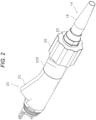
- Fig. 2 is an enlarged view enlarging and displaying the operation unit 20 and the bend preventing portion 16 of the endoscope 10 according to the first embodiment
- Fig. 3 is a cross-sectional view of the operation unit 20 and the bend preventing portion 16 along an axial direction
- Fig. 4 is an explanatory view illustrating a configuration of an inner side of the cylindrical handle 26 in Fig. 2
- Fig. 5 is a cross-sectional view representing a state where the cylindrical handle 26 and the bend preventing portion 16 are rotated by a predetermined angle about an axial center.
- Fig. 4 illustrates only an outline of the cylindrical handle 26 for convenience. Note that, in Figs. 3 and 5 , a cross section of an O-ring is indicated by a black circle.
- the operation unit 20 is provided with a rotary cylindrical portion 27 having one end portion connected to one end portion of the bend preventing portion 16 at the end portion on the side of the bend preventing portion 16.
- the operation unit 20 includes a holding cylindrical portion 28, and the rotary cylindrical portion 27 is rotatably held by the holding cylindrical portion 28.
- the holding cylindrical portion 28 has a cylindrical shape, and is internally fitted to the one end portion of the grip portion 205 on the side of the bend preventing portion 16.
- a protrusion 281 is circumferentially provided in an annular shape at a substantially intermediate position in the axial direction on an inner peripheral surface of the holding cylindrical portion 28.
- the rotary cylindrical portion 27 has a substantially cylindrical shape, has the other end portion internally fitted to the holding cylindrical portion 28, and has the one end portion externally fitted to the one end portion of the bend preventing portion 16.
- a groove is formed in a circumferential direction on an outer peripheral surface of the other end portion of the rotary cylindrical portion 27, and such a groove is engaged with the protrusion 281 of the holding cylindrical portion 28. With this configuration, movement of the rotary cylindrical portion 27 in the axial direction is restricted.
- the rotary cylindrical portion 27 includes a first cylindrical portion 271 on a side of the one end portion and a second cylindrical portion 272 on a side of the other end portion.
- the first cylindrical portion 271 and the second cylindrical portion 272 are coaxially disposed and fitted.
- One end portion of the first cylindrical portion 271 has an enlarged inner diameter, and is externally fitted to a diameter-reduced portion 161 provided at the one end portion of the bend preventing portion 16.
- An O-ring is interposed between the one end portion of the first cylindrical portion 271 and the diameter-reduced portion 161 of the bend preventing portion 16.
- a screw hole penetrating in a radial direction is formed at the one end portion of the first cylindrical portion 271, and a recess is formed on an outer peripheral surface of the diameter-reduced portion 161 corresponding to such a screw hole.
- the bend preventing portion 16 is integrated with the first cylindrical portion 271 (rotary cylindrical portion 27) and rotates together with the rotary cylindrical portion 27 as described above (see Fig. 5 ).
- the other end portion of the first cylindrical portion 271 has an enlarged inner diameter on a side of the second cylindrical portion 272, and is externally fitted to one end portion of the second cylindrical portion 272.
- first cylindrical portion 271 of the rotary cylindrical portion 27 is provided with a connection portion 273 that connects the rotary cylindrical portion 27 with the cylindrical handle 26.
- the connection portion 273 protrudes outward in the radial direction at one portion on an outer peripheral surface of the first cylindrical portion 271 (see Fig. 4 ), and has a distal tip bent toward the side of the second cylindrical portion 272.
- a distal tip surface of the connection portion 273 in the axial direction of the rotary cylindrical portion 27 is flush with a bottom surface 261A of a bottom 261 to be described later of the cylindrical handle 26.
- first cylindrical portion 271 or the second cylindrical portion 272 is also referred to as the rotary cylindrical portion 27.
- the holding cylindrical portion 28 is formed with a cutout 282 at an end portion on the side of the bend preventing portion 16.
- the cutout 282 is formed in a part of the end portion along the circumferential direction.
- the connection portion 273 is disposed inside the cutout 282, and an edge of the cutout 282 in the axial direction of the holding cylindrical portion 28 is positioned between the outer peripheral surface of the first cylindrical portion 271 and the bent distal tip of the connection portion 273. Therefore, when the rotary cylindrical portion 27 rotates about the axial center, the connection portion 273 also moves in the cutout 282, but a movement range of the connection portion 273 is restricted to between both edges of the cutout 282 in the circumferential direction. That is, a rotation range of the rotary cylindrical portion 27 is restricted within a predetermined angle.
- the cylindrical handle 26 has a bottomed cylindrical shape, and has one end portion in the axial direction externally fitted to the one end portion of the grip portion 205.
- An O-ring is interposed between the one end portion of the cylindrical handle 26 and the one end portion of the grip portion 205.
- the cylindrical handle 26 has the bottom 261 at the other end portion in the axial direction, and the rotary cylindrical portion 27 penetrates the bottom 261 from the inside to the outside. That is, a through hole 262 is formed in a central portion of the bottom 261, and the rotary cylindrical portion 27 (first cylindrical portion 271) is internally fitted to the through hole 262.
- An O-ring is interposed between the first cylindrical portion 271 and an inner peripheral surface of the through hole 262.
- an engagement recess 263 having a shape following the connection portion 273 and engaged with the connection portion 273 is formed. Therefore, in a case where the cylindrical handle 26 rotates, the rotary cylindrical portion 27 and the bend preventing portion 16 (insertion portion 14) also rotate together.
- a fixing cylinder 50 for fixing the cylindrical handle 26 is provided at the one end portion of the first cylindrical portion 271 of the rotary cylindrical portion 27 outside the bottom 261 of the cylindrical handle 26.
- the fixing cylinder 50 has a substantially cylindrical shape, and is externally fitted to the one end portion of the first cylindrical portion 271.
- An O-ring is interposed between the fixing cylinder 50 and the one end portion of the first cylindrical portion 271.
- a positioning nut 29 (contact portion) that determines a positional relationship between the grip portion 205 and the holding cylindrical portion 28 is provided outside the holding cylindrical portion 28.
- the positioning nut 29 has an annular body shape having a rectangular cross section, and is screwed with a thread (not illustrated) formed on an outer peripheral surface of the holding cylindrical portion 28. At this time, one end in the axial direction of the positioning nut 29 is in contact with the one end portion of the grip portion 205.
- a rotation suppression member 30 is disposed outside the holding cylindrical portion 28 and between the bottom 261 of the cylindrical handle 26 and the positioning nut 29.
- the rotation suppression member 30 is externally fitted to the holding cylindrical portion 28.
- the rotation suppression member 30 has a ring shape having a circular cross section (see Fig. 4 or Fig. 5 ), and includes a material having excellent frictional resistance, such as rubber or silicon.
- the rotation suppression member 30 contacts the bottom 261 of the cylindrical handle 26 to suppress rotation of the cylindrical handle 26. That is, the rotation suppression member 30 contacts the other end in the axial direction of the positioning nut 29, contacts the outer peripheral surface of the holding cylindrical portion 28, and also contacts the bottom surface 261A of the cylindrical handle 26. Therefore, rotation of the cylindrical handle 26 is suppressed by frictional resistance generated between the rotation suppression member 30 and the bottom surface 261A of the cylindrical handle 26. Accordingly, rotation of the insertion portion 14 connected to the cylindrical handle 26 is also suppressed.
- the rotation suppression member 30 is disposed away from an inner surface of the cylindrical handle 26. That is, a gap 100 is formed between the rotation suppression member 30 and the cylindrical handle 26 in the radial direction.
- the endoscope 10 according to the first embodiment having the above-described configuration can prevent the insertion portion 14 from rotating at timing not intended by the user in advance.
- the rotation suppression member 30 contacts the other end in the axial direction of the positioning nut 29, contacts the outer peripheral surface of the holding cylindrical portion 28, and also contacts the bottom surface 261A of the cylindrical handle 26.
- rotation of the cylindrical handle 26 is suppressed by frictional resistance generated between the other end in the axial direction of the positioning nut 29 and the rotation suppression member 30, between the outer peripheral surface of the holding cylindrical portion 28 and the rotation suppression member 30, and between the bottom surface 261A of the cylindrical handle 26 and the rotation suppression member 30. That is, unless an external force is applied, that is, unless a user who desires rotation of the insertion portion 14 intentionally rotates the cylindrical handle 26, the rotation of the insertion portion 14 is suppressed.
- the gap 100 is formed between the rotation suppression member 30 and the cylindrical handle 26 in the radial direction, and as described above, the rotation suppression member 30 contacts the cylindrical handle 26 (bottom surface 261A) only in the axial direction. Therefore, damage to the rotation suppression member 30 at the time of assembly can be prevented. The details will be described below.
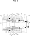
- Fig. 6 is an explanatory view representing a process of assembling the cylindrical handle 26 in the endoscope 10 according to the first embodiment.
- a state where the assembly is completed is illustrated, and a broken line indicates the cylindrical handle 26 in the middle of being assembled.
- a state before the fixing cylinder 50 for fixing the cylindrical handle 26 is assembled is illustrated.
- the cylindrical handle 26 is fitted to the rotary cylindrical portion 27 from the side of the bend preventing portion 16, and is externally fitted to the rotary cylindrical portion 27 (first cylindrical portion 271) as described above. At this time, as illustrated in Fig. 6 , the cylindrical handle 26 moves in an arrow direction of Fig. 6 on the outer peripheral surface of the rotary cylindrical portion 27. However, since the gap 100 is formed between the rotation suppression member 30 and the cylindrical handle 26, the inner surface of the cylindrical handle 26 does not contact the rotation suppression member 30, and the rotation suppression member 30 is not rubbed. Therefore, workability of assembly work can be enhanced, and damage to the rotation suppression member 30 at the time of assembly can be prevented.
- Fig. 7 is a partial cross-sectional view illustrating a main configuration of the endoscope 10 according to a modification of the first embodiment.
- the endoscope 10 according to the modification includes a rotation suppression member 30A, and a shape of the rotation suppression member 30A is different from that of the rotation suppression member 30 of the first embodiment.
- the rotation suppression member 30A is disposed outside the holding cylindrical portion 28 and between the bottom 261 of the cylindrical handle 26 and the positioning nut 29.
- the rotation suppression member 30A is externally fitted to the holding cylindrical portion 28.
- the rotation suppression member 30A has an annular body shape having a rectangular cross section, and includes a material having excellent frictional resistance, such as rubber or silicon.
- the rotation suppression member 30A contacts the other end in the axial direction of the positioning nut 29, contacts the outer peripheral surface of the holding cylindrical portion 28, and also contacts the bottom surface 261A of the cylindrical handle 26. Therefore, frictional resistance generated between the rotation suppression member 30A and the bottom surface 261A of the cylindrical handle 26 suppresses rotation of the cylindrical handle 26, and also suppresses rotation of the insertion portion 14 connected with the cylindrical handle 26.
- the gap 100 is formed between the rotation suppression member 30A and the cylindrical handle 26 in the radial direction.
- the rotation suppression member 30A contacts the other end in the axial direction of the positioning nut 29, contacts the outer peripheral surface of the holding cylindrical portion 28, and also contacts the bottom surface 261A of the cylindrical handle 26. Since the rotation suppression member 30A has the rectangular cross section, a contact area with the other end in the axial direction of the positioning nut 29, a contact area with the outer peripheral surface of the holding cylindrical portion 28, and a contact area with the bottom surface 261A of the cylindrical handle 26 can be further expanded. Therefore, frictional resistance generated between the other end in the axial direction of the positioning nut 29 and the rotation suppression member 30A, between the outer peripheral surface of the holding cylindrical portion 28 and the rotation suppression member 30A, and between the bottom surface 261A of the cylindrical handle 26 and the rotation suppression member 30A increases. Therefore, it is possible to more effectively prevent the insertion portion 14 from rotating at timing not intended by a user.
- the gap 100 is formed between the rotation suppression member 30A and the cylindrical handle 26 in the radial direction, and the rotation suppression member 30A contacts the cylindrical handle 26 (bottom surface 261A) only in the axial direction. Therefore, workability of assembly work can be enhanced, and it is possible to prevent the rotation suppression member 30A from being damaged by being rubbed by contacting the cylindrical handle 26 at the time of assembly.
- Fig. 8 is a partial cross-sectional view illustrating a main configuration of an endoscope 10 according to a second embodiment. For convenience, in Fig. 8 , vicinity of a rotary cylindrical portion 27 is illustrated in an enlarged manner.
- a rotation suppression member 30 is disposed outside a holding cylindrical portion 28 and between a bottom 261 of a cylindrical handle 26 and a positioning nut 29.
- the rotation suppression member 30 is externally fitted to the holding cylindrical portion 28.
- the rotation suppression member 30 has a ring shape having a circular cross section, and includes a material having excellent frictional resistance, such as rubber or silicon.
- the rotation suppression member 30 contacts the other end in an axial direction of the positioning nut 29, contacts an outer peripheral surface of the holding cylindrical portion 28, and also contacts a bottom surface 261A of the cylindrical handle 26.
- a groove 264 is formed at a position facing the rotation suppression member 30 in the axial direction. That is, the groove 264 is formed in a circular shape in a circumferential direction of the holding cylindrical portion 28.
- the groove 264 has a curved surface corresponding to the rotation suppression member 30 on an inner side, and the rotation suppression member 30 is partially housed in the groove 264.
- frictional resistance generated between the rotation suppression member 30 and the bottom surface 261A of the cylindrical handle 26 suppresses rotation of the cylindrical handle 26, and also suppresses rotation of an insertion portion 14 connected with the cylindrical handle 26.
- a gap 100 is formed between the rotation suppression member 30 and the cylindrical handle 26 in a radial direction.
- the rotation suppression member 30 contacts the other end in the axial direction of the positioning nut 29, contacts the outer peripheral surface of the holding cylindrical portion 28, and also contacts the bottom surface 261A of the cylindrical handle 26.
- the groove 264 is formed in the bottom surface 261A of the cylindrical handle 26 and the rotation suppression member 30 is partially housed in the groove 264, a large contact area between the rotation suppression member 30 and the bottom surface 261A of the cylindrical handle 26 can be secured. Therefore, frictional resistance generated between the bottom surface 261A of the cylindrical handle 26 and the rotation suppression member 30 increases. Therefore, it is possible to more effectively prevent the insertion portion 14 from rotating at timing not intended by a user.
- the rotation suppression member 30 is partially housed in the groove 264, a position of the rotation suppression member 30 is determined, and deviation of the position of the rotation suppression member 30 from a normal position can be suppressed.
- the gap 100 is formed between the rotation suppression member 30 and the cylindrical handle 26 in the radial direction, and the rotation suppression member 30 contacts the cylindrical handle 26 (bottom surface 261A) only in the axial direction. Therefore, workability of assembly work can be enhanced, and it is possible to prevent the rotation suppression member 30 from being damaged by being rubbed by contacting the cylindrical handle 26 at the time of assembly.
- Fig. 9 is a partial cross-sectional view illustrating a main configuration of an endoscope 10 according to a third embodiment. For convenience, in Fig. 9 , vicinity of a rotary cylindrical portion 27 is illustrated in an enlarged manner.
- a rotation suppression member 30 is disposed outside a holding cylindrical portion 28 and between a bottom 261 of a cylindrical handle 26 and a positioning nut 29.
- the rotation suppression member 30 is externally fitted to the holding cylindrical portion 28.
- the rotation suppression member 30 has a ring shape having a circular cross section, and includes a material having excellent frictional resistance, such as rubber or silicon.
- the rotation suppression member 30 contacts the other end in an axial direction of the positioning nut 29, contacts an outer peripheral surface of the holding cylindrical portion 28, and also contacts a bottom surface 261A of the cylindrical handle 26.
- a groove 291 is formed at a position facing the rotation suppression member 30 in the axial direction. That is, the groove 291 is formed in a circular shape along the other end surface in the axial direction of the positioning nut 29.
- the groove 291 has a curved surface corresponding to the rotation suppression member 30 on an inner side, and the rotation suppression member 30 is partially housed in the groove 291.
- frictional resistance generated between the rotation suppression member 30 and the bottom surface 261A of the cylindrical handle 26 suppresses rotation of the cylindrical handle 26, and also suppresses rotation of an insertion portion 14 connected with the cylindrical handle 26.
- a gap 100 is formed between the rotation suppression member 30 and the cylindrical handle 26 in a radial direction.
- the rotation suppression member 30 contacts the other end in the axial direction of the positioning nut 29, contacts the outer peripheral surface of the holding cylindrical portion 28, and also contacts the bottom surface 261A of the cylindrical handle 26.
- the groove 291 is formed at the other end in the axial direction of the positioning nut 29 and the rotation suppression member 30 is partially housed in the groove 291, a contact area between the rotation suppression member 30 and the other end in the axial direction of the positioning nut 29 can be increased. Therefore, frictional resistance generated between the other end in the axial direction of the positioning nut 29 and the rotation suppression member 30 increases, and a suppression force for suppressing movement of the rotation suppression member 30 increases. Therefore, it is possible to improve a rotation prevention effect of the cylindrical handle 26 due to frictional resistance with the rotation suppression member 30, and it is possible to more effectively prevent the insertion portion 14 from rotating at timing not intended by a user.
- the rotation suppression member 30 is partially housed in the groove 291, a position of the rotation suppression member 30 is determined, and deviation of the position of the rotation suppression member 30 from a normal position can be suppressed.
- the gap 100 is formed between the rotation suppression member 30 and the cylindrical handle 26 in the radial direction, and the rotation suppression member 30 contacts the cylindrical handle 26 (bottom surface 261A) only in the axial direction. Therefore, workability of assembly work can be enhanced, and it is possible to prevent the rotation suppression member 30 from being damaged by being rubbed by contacting the cylindrical handle 26 at the time of assembly.
- the rotation suppression member 30 may be disposed away from the outer peripheral surface of the holding cylindrical portion 28. That is, a gap may be formed between the rotation suppression member 30 and the outer peripheral surface of the holding cylindrical portion 28 in the radial direction. At this time, it is possible to further prevent the rotation suppression member 30 from being damaged by being rubbed by contacting the holding cylindrical portion 28.
Landscapes
- Health & Medical Sciences (AREA)
- Life Sciences & Earth Sciences (AREA)
- Surgery (AREA)
- Biomedical Technology (AREA)
- Medical Informatics (AREA)
- Optics & Photonics (AREA)
- Pathology (AREA)
- Radiology & Medical Imaging (AREA)
- Biophysics (AREA)
- Engineering & Computer Science (AREA)
- Physics & Mathematics (AREA)
- Heart & Thoracic Surgery (AREA)
- Nuclear Medicine, Radiotherapy & Molecular Imaging (AREA)
- Molecular Biology (AREA)
- Animal Behavior & Ethology (AREA)
- General Health & Medical Sciences (AREA)
- Public Health (AREA)
- Veterinary Medicine (AREA)
- Endoscopes (AREA)
- Instruments For Viewing The Inside Of Hollow Bodies (AREA)
Abstract
Description
- The present invention relates to an endoscope including an insertion portion to be inserted into a body lumen.
- Conventionally, an endoscope that images an affected part by inserting an insertion portion into a body lumen or the like of a patient and operating an operation unit has been widely used.
- For example, Patent Literature 1 discloses an endoscope in which a torque control member is provided between an operation-unit mouthpiece part and an insertion-unit mouthpiece part in a radial direction at an engagement part between the operation-unit mouthpiece part and the insertion-unit mouthpiece part, and frictional resistance by the torque control member is used to prevent an insertion unit from rotating at timing not intended by a user.
- Patent Literature 1:
WO 2012/164978 A1 - However, in the endoscope of Patent Literature 1, since the torque control member is provided between the operation-unit mouthpiece part and the insertion-unit mouthpiece part in the radial direction, friction between the torque control member and the operation-unit mouthpiece part or the insertion-unit mouthpiece part occurs at the time of assembly work of engaging the operation-unit mouthpiece part and the insertion-unit mouthpiece part. Therefore, such assembly work may be delayed, and eventually, fracture, early deterioration, and the like of the torque control member may occur.
- The present invention has been achieved in view of such circumstances, and an object thereof is to provide an endoscope capable of preventing unintended rotation of an insertion portion while facilitating assembly work.
- An endoscope according to the present invention is an endoscope including: a rotary cylindrical portion that is connected with an insertion portion to be inserted into a body lumen and rotates together with the insertion portion; and an operation unit that operates the insertion portion, and the endoscope further includes: a cylindrical handle that has a bottom in which a through hole into which the rotary cylindrical portion is internally fitted is formed and that rotates the rotary cylindrical portion; and a rotation suppression member that is provided in the operation unit, contacts the bottom of the cylindrical handle, and suppresses rotation of the cylindrical handle.
- In the present invention, the rotation suppression member contacts the bottom of the cylindrical handle to suppress rotation of the cylindrical handle, so that rotation of the rotary cylindrical portion is suppressed through the cylindrical handle. With this configuration, it is possible to prevent the insertion portion connected to the rotary cylindrical portion from rotating regardless of intention of a user.
- According to the present invention, it is possible to provide an endoscope capable of preventing unintended rotation of an insertion portion while facilitating assembly work.
-
-
Fig. 1 is an external view of an endoscope according to a first embodiment of the present invention. -
Fig. 2 is an enlarged view enlarging and displaying an operation unit and a bend preventing portion of the endoscope according to the first embodiment. -
Fig. 3 is a cross-sectional view of the operation unit and the bend preventing portion along an axial direction. -
Fig. 4 is an explanatory view illustrating a configuration of an inner side of a cylindrical handle inFig. 2 . -
Fig. 5 is a cross-sectional view representing a state where the cylindrical handle and the bend preventing portion are rotated by a predetermined angle about an axial center. -
Fig. 6 is an explanatory view representing a process of assembling the cylindrical handle in the endoscope according to the first embodiment. -
Fig. 7 is a partial cross-sectional view illustrating a main configuration of the endoscope according to a modification of the first embodiment. -
Fig. 8 is a partial cross-sectional view illustrating a main configuration of an endoscope according to a second embodiment. -
Fig. 9 is a partial cross-sectional view illustrating a main configuration of an endoscope according to a third embodiment. - Hereinafter, an endoscope according to embodiments of the present invention will be described in detail with reference to the drawings.
-
Fig. 1 is an external view of anendoscope 10 according to a first embodiment of the present invention. - The
endoscope 10 of the present embodiment includes aninsertion portion 14 to be inserted into a body lumen of a subject, anoperation unit 20 for operating theinsertion portion 14, and aconnector unit 24 connected with a processor (not illustrated). - The
insertion portion 14 includes abend preventing portion 16 and is connected with theoperation unit 20 through thebend preventing portion 16, and theconnector unit 24 is connected with theoperation unit 20 through auniversal cord 25. - The
universal cord 25 has pliability, and includes an electric line that sends, to theconnector unit 24, image data (electric signal) from an imaging unit (not illustrated) of animaging portion 13 to be described later provided at a distal tip of theinsertion portion 14. - The
operation unit 20 includes agrip portion 205,buttons 210 for receiving an instruction from a user, and a bending operation lever 21 for operating a bending motion of theinsertion portion 14. - The
grip portion 205 has a substantially cylindrical shape whose diameter gradually decreases toward thebend preventing portion 16, and achannel inlet 22, into which a treatment tool or the like is to be inserted, is provided near a side of thebend preventing portion 16. Thegrip portion 205 is disposed on the same axial center as thebend preventing portion 16 having a substantially cylindrical shape as described later. - Furthermore, the operation unit 20 (grip portion 205) is provided with a
cylindrical handle 26 that rotates theinsertion portion 14 at an end portion near thebend preventing portion 16. In a case where a user rotates thecylindrical handle 26, theinsertion portion 14 rotates. - The
insertion portion 14 includes theimaging portion 13 on a side of the distal tip, and theimaging portion 13 has a cylindrical shape with a small diameter. Furthermore, thebend preventing portion 16 has the substantially cylindrical shape whose diameter gradually decreases toward theinsertion portion 14, and suppresses sudden bending of theinsertion portion 14. - The
imaging portion 13 includes the imaging unit including imaging means such as a charge coupled device (CCD) or a complementary metal oxide semiconductor (CMOS), a circuit board for driving the imaging means, an observation optical system, and the like, and a lens unit (not illustrated) including a series of lens sets. Furthermore, theimaging portion 13 includes an illumination optical system (not illustrated) or the like for irradiating an observation target site in a body lumen with light. An electric signal from the imaging unit of theimaging portion 13 is sent to the processor through theconnector unit 24. - As described above, the
insertion portion 14 can be bent by an operation of theoperation unit 20. That is, theinsertion portion 14 is freely bent in two directions in accordance with an operation of thebending operation lever 21. -
Fig. 2 is an enlarged view enlarging and displaying theoperation unit 20 and thebend preventing portion 16 of theendoscope 10 according to the first embodiment,Fig. 3 is a cross-sectional view of theoperation unit 20 and thebend preventing portion 16 along an axial direction,Fig. 4 is an explanatory view illustrating a configuration of an inner side of thecylindrical handle 26 inFig. 2 , andFig. 5 is a cross-sectional view representing a state where thecylindrical handle 26 and thebend preventing portion 16 are rotated by a predetermined angle about an axial center.Fig. 4 illustrates only an outline of thecylindrical handle 26 for convenience. Note that, inFigs. 3 and5 , a cross section of an O-ring is indicated by a black circle. - The
operation unit 20 is provided with a rotarycylindrical portion 27 having one end portion connected to one end portion of thebend preventing portion 16 at the end portion on the side of thebend preventing portion 16. Specifically, theoperation unit 20 includes a holdingcylindrical portion 28, and the rotarycylindrical portion 27 is rotatably held by the holdingcylindrical portion 28. - The holding
cylindrical portion 28 has a cylindrical shape, and is internally fitted to the one end portion of thegrip portion 205 on the side of thebend preventing portion 16. Aprotrusion 281 is circumferentially provided in an annular shape at a substantially intermediate position in the axial direction on an inner peripheral surface of the holdingcylindrical portion 28. - The rotary
cylindrical portion 27 has a substantially cylindrical shape, has the other end portion internally fitted to the holdingcylindrical portion 28, and has the one end portion externally fitted to the one end portion of thebend preventing portion 16. A groove is formed in a circumferential direction on an outer peripheral surface of the other end portion of the rotarycylindrical portion 27, and such a groove is engaged with theprotrusion 281 of the holdingcylindrical portion 28. With this configuration, movement of the rotarycylindrical portion 27 in the axial direction is restricted. - The rotary
cylindrical portion 27 includes a firstcylindrical portion 271 on a side of the one end portion and a secondcylindrical portion 272 on a side of the other end portion. - The first
cylindrical portion 271 and the secondcylindrical portion 272 are coaxially disposed and fitted. - One end portion of the first
cylindrical portion 271 has an enlarged inner diameter, and is externally fitted to a diameter-reducedportion 161 provided at the one end portion of thebend preventing portion 16. An O-ring is interposed between the one end portion of the firstcylindrical portion 271 and the diameter-reducedportion 161 of thebend preventing portion 16. Furthermore, a screw hole penetrating in a radial direction is formed at the one end portion of the firstcylindrical portion 271, and a recess is formed on an outer peripheral surface of the diameter-reducedportion 161 corresponding to such a screw hole. When a so-called setscrew S is inserted through the screw hole and an end portion of the setscrew S is engaged with the recess of the diameter-reducedportion 161, thebend preventing portion 16 is integrated with the first cylindrical portion 271 (rotary cylindrical portion 27) and rotates together with the rotarycylindrical portion 27 as described above (seeFig. 5 ). - Furthermore, the other end portion of the first
cylindrical portion 271 has an enlarged inner diameter on a side of the secondcylindrical portion 272, and is externally fitted to one end portion of the secondcylindrical portion 272. - Furthermore, the first
cylindrical portion 271 of the rotarycylindrical portion 27 is provided with aconnection portion 273 that connects the rotarycylindrical portion 27 with thecylindrical handle 26. Theconnection portion 273 protrudes outward in the radial direction at one portion on an outer peripheral surface of the first cylindrical portion 271 (seeFig. 4 ), and has a distal tip bent toward the side of the secondcylindrical portion 272. A distal tip surface of theconnection portion 273 in the axial direction of the rotarycylindrical portion 27 is flush with abottom surface 261A of a bottom 261 to be described later of thecylindrical handle 26. - Note that, hereinafter, the first
cylindrical portion 271 or the secondcylindrical portion 272 is also referred to as the rotarycylindrical portion 27. - The holding
cylindrical portion 28 is formed with acutout 282 at an end portion on the side of thebend preventing portion 16. Thecutout 282 is formed in a part of the end portion along the circumferential direction. Theconnection portion 273 is disposed inside thecutout 282, and an edge of thecutout 282 in the axial direction of the holdingcylindrical portion 28 is positioned between the outer peripheral surface of the firstcylindrical portion 271 and the bent distal tip of theconnection portion 273. Therefore, when the rotarycylindrical portion 27 rotates about the axial center, theconnection portion 273 also moves in thecutout 282, but a movement range of theconnection portion 273 is restricted to between both edges of thecutout 282 in the circumferential direction. That is, a rotation range of the rotarycylindrical portion 27 is restricted within a predetermined angle. - The
cylindrical handle 26 has a bottomed cylindrical shape, and has one end portion in the axial direction externally fitted to the one end portion of thegrip portion 205. An O-ring is interposed between the one end portion of thecylindrical handle 26 and the one end portion of thegrip portion 205. Furthermore, thecylindrical handle 26 has the bottom 261 at the other end portion in the axial direction, and the rotarycylindrical portion 27 penetrates the bottom 261 from the inside to the outside. That is, a throughhole 262 is formed in a central portion of the bottom 261, and the rotary cylindrical portion 27 (first cylindrical portion 271) is internally fitted to the throughhole 262. An O-ring is interposed between the firstcylindrical portion 271 and an inner peripheral surface of the throughhole 262. - Furthermore, in the bottom 261, at a position corresponding to the
connection portion 273, anengagement recess 263 having a shape following theconnection portion 273 and engaged with theconnection portion 273 is formed. Therefore, in a case where thecylindrical handle 26 rotates, the rotarycylindrical portion 27 and the bend preventing portion 16 (insertion portion 14) also rotate together. - A fixing
cylinder 50 for fixing thecylindrical handle 26 is provided at the one end portion of the firstcylindrical portion 271 of the rotarycylindrical portion 27 outside thebottom 261 of thecylindrical handle 26. The fixingcylinder 50 has a substantially cylindrical shape, and is externally fitted to the one end portion of the firstcylindrical portion 271. An O-ring is interposed between the fixingcylinder 50 and the one end portion of the firstcylindrical portion 271. - Additionally, a positioning nut 29 (contact portion) that determines a positional relationship between the
grip portion 205 and the holdingcylindrical portion 28 is provided outside the holdingcylindrical portion 28. Thepositioning nut 29 has an annular body shape having a rectangular cross section, and is screwed with a thread (not illustrated) formed on an outer peripheral surface of the holdingcylindrical portion 28. At this time, one end in the axial direction of thepositioning nut 29 is in contact with the one end portion of thegrip portion 205. - A
rotation suppression member 30 is disposed outside the holdingcylindrical portion 28 and between the bottom 261 of thecylindrical handle 26 and thepositioning nut 29. Therotation suppression member 30 is externally fitted to the holdingcylindrical portion 28. For example, therotation suppression member 30 has a ring shape having a circular cross section (seeFig. 4 orFig. 5 ), and includes a material having excellent frictional resistance, such as rubber or silicon. - The
rotation suppression member 30 contacts thebottom 261 of thecylindrical handle 26 to suppress rotation of thecylindrical handle 26. That is, therotation suppression member 30 contacts the other end in the axial direction of thepositioning nut 29, contacts the outer peripheral surface of the holdingcylindrical portion 28, and also contacts thebottom surface 261A of thecylindrical handle 26. Therefore, rotation of thecylindrical handle 26 is suppressed by frictional resistance generated between therotation suppression member 30 and thebottom surface 261A of thecylindrical handle 26. Accordingly, rotation of theinsertion portion 14 connected to thecylindrical handle 26 is also suppressed. - On the other hand, the
rotation suppression member 30 is disposed away from an inner surface of thecylindrical handle 26. That is, agap 100 is formed between therotation suppression member 30 and thecylindrical handle 26 in the radial direction. - The
endoscope 10 according to the first embodiment having the above-described configuration can prevent theinsertion portion 14 from rotating at timing not intended by the user in advance. - As described above, the
rotation suppression member 30 contacts the other end in the axial direction of thepositioning nut 29, contacts the outer peripheral surface of the holdingcylindrical portion 28, and also contacts thebottom surface 261A of thecylindrical handle 26. At this time, rotation of thecylindrical handle 26 is suppressed by frictional resistance generated between the other end in the axial direction of thepositioning nut 29 and therotation suppression member 30, between the outer peripheral surface of the holdingcylindrical portion 28 and therotation suppression member 30, and between thebottom surface 261A of thecylindrical handle 26 and therotation suppression member 30. That is, unless an external force is applied, that is, unless a user who desires rotation of theinsertion portion 14 intentionally rotates thecylindrical handle 26, the rotation of theinsertion portion 14 is suppressed. - Furthermore, in the
endoscope 10 according to the first embodiment, thegap 100 is formed between therotation suppression member 30 and thecylindrical handle 26 in the radial direction, and as described above, therotation suppression member 30 contacts the cylindrical handle 26 (bottom surface 261A) only in the axial direction. Therefore, damage to therotation suppression member 30 at the time of assembly can be prevented. The details will be described below. -
Fig. 6 is an explanatory view representing a process of assembling thecylindrical handle 26 in theendoscope 10 according to the first embodiment. InFig. 6 , a state where the assembly is completed is illustrated, and a broken line indicates thecylindrical handle 26 in the middle of being assembled. Furthermore, inFig. 6 , a state before the fixingcylinder 50 for fixing thecylindrical handle 26 is assembled is illustrated. - The
cylindrical handle 26 is fitted to the rotarycylindrical portion 27 from the side of thebend preventing portion 16, and is externally fitted to the rotary cylindrical portion 27 (first cylindrical portion 271) as described above. At this time, as illustrated inFig. 6 , thecylindrical handle 26 moves in an arrow direction ofFig. 6 on the outer peripheral surface of the rotarycylindrical portion 27. However, since thegap 100 is formed between therotation suppression member 30 and thecylindrical handle 26, the inner surface of thecylindrical handle 26 does not contact therotation suppression member 30, and therotation suppression member 30 is not rubbed. Therefore, workability of assembly work can be enhanced, and damage to therotation suppression member 30 at the time of assembly can be prevented. -
Fig. 7 is a partial cross-sectional view illustrating a main configuration of theendoscope 10 according to a modification of the first embodiment. For convenience, inFig. 7 , vicinity of the rotarycylindrical portion 27 is illustrated in an enlarged manner. Theendoscope 10 according to the modification includes arotation suppression member 30A, and a shape of therotation suppression member 30A is different from that of therotation suppression member 30 of the first embodiment. - The
rotation suppression member 30A is disposed outside the holdingcylindrical portion 28 and between the bottom 261 of thecylindrical handle 26 and thepositioning nut 29. Therotation suppression member 30A is externally fitted to the holdingcylindrical portion 28. For example, therotation suppression member 30A has an annular body shape having a rectangular cross section, and includes a material having excellent frictional resistance, such as rubber or silicon. - The
rotation suppression member 30A contacts the other end in the axial direction of thepositioning nut 29, contacts the outer peripheral surface of the holdingcylindrical portion 28, and also contacts thebottom surface 261A of thecylindrical handle 26. Therefore, frictional resistance generated between therotation suppression member 30A and thebottom surface 261A of thecylindrical handle 26 suppresses rotation of thecylindrical handle 26, and also suppresses rotation of theinsertion portion 14 connected with thecylindrical handle 26. - On the other hand, as in the first embodiment, the
gap 100 is formed between therotation suppression member 30A and thecylindrical handle 26 in the radial direction. - With the above configuration, the
rotation suppression member 30A contacts the other end in the axial direction of thepositioning nut 29, contacts the outer peripheral surface of the holdingcylindrical portion 28, and also contacts thebottom surface 261A of thecylindrical handle 26. Since therotation suppression member 30A has the rectangular cross section, a contact area with the other end in the axial direction of thepositioning nut 29, a contact area with the outer peripheral surface of the holdingcylindrical portion 28, and a contact area with thebottom surface 261A of thecylindrical handle 26 can be further expanded. Therefore, frictional resistance generated between the other end in the axial direction of thepositioning nut 29 and therotation suppression member 30A, between the outer peripheral surface of the holdingcylindrical portion 28 and therotation suppression member 30A, and between thebottom surface 261A of thecylindrical handle 26 and therotation suppression member 30A increases. Therefore, it is possible to more effectively prevent theinsertion portion 14 from rotating at timing not intended by a user. - Furthermore, in the
endoscope 10 according to the modification, thegap 100 is formed between therotation suppression member 30A and thecylindrical handle 26 in the radial direction, and therotation suppression member 30A contacts the cylindrical handle 26 (bottom surface 261A) only in the axial direction. Therefore, workability of assembly work can be enhanced, and it is possible to prevent therotation suppression member 30A from being damaged by being rubbed by contacting thecylindrical handle 26 at the time of assembly. -
Fig. 8 is a partial cross-sectional view illustrating a main configuration of anendoscope 10 according to a second embodiment. For convenience, inFig. 8 , vicinity of a rotarycylindrical portion 27 is illustrated in an enlarged manner. - In the
endoscope 10 according to the second embodiment, as in the first embodiment, arotation suppression member 30 is disposed outside a holdingcylindrical portion 28 and between a bottom 261 of acylindrical handle 26 and apositioning nut 29. Therotation suppression member 30 is externally fitted to the holdingcylindrical portion 28. For example, therotation suppression member 30 has a ring shape having a circular cross section, and includes a material having excellent frictional resistance, such as rubber or silicon. - The
rotation suppression member 30 contacts the other end in an axial direction of thepositioning nut 29, contacts an outer peripheral surface of the holdingcylindrical portion 28, and also contacts abottom surface 261A of thecylindrical handle 26. - More specifically, on the
bottom surface 261A of thecylindrical handle 26, agroove 264 is formed at a position facing therotation suppression member 30 in the axial direction. That is, thegroove 264 is formed in a circular shape in a circumferential direction of the holdingcylindrical portion 28. Thegroove 264 has a curved surface corresponding to therotation suppression member 30 on an inner side, and therotation suppression member 30 is partially housed in thegroove 264. - At this time, frictional resistance generated between the
rotation suppression member 30 and thebottom surface 261A of thecylindrical handle 26 suppresses rotation of thecylindrical handle 26, and also suppresses rotation of aninsertion portion 14 connected with thecylindrical handle 26. - On the other hand, as in the first embodiment, a
gap 100 is formed between therotation suppression member 30 and thecylindrical handle 26 in a radial direction. - With the above configuration, the
rotation suppression member 30 contacts the other end in the axial direction of thepositioning nut 29, contacts the outer peripheral surface of the holdingcylindrical portion 28, and also contacts thebottom surface 261A of thecylindrical handle 26. - Moreover, since the
groove 264 is formed in thebottom surface 261A of thecylindrical handle 26 and therotation suppression member 30 is partially housed in thegroove 264, a large contact area between therotation suppression member 30 and thebottom surface 261A of thecylindrical handle 26 can be secured. Therefore, frictional resistance generated between thebottom surface 261A of thecylindrical handle 26 and therotation suppression member 30 increases. Therefore, it is possible to more effectively prevent theinsertion portion 14 from rotating at timing not intended by a user. - Furthermore, as described above, since the
rotation suppression member 30 is partially housed in thegroove 264, a position of therotation suppression member 30 is determined, and deviation of the position of therotation suppression member 30 from a normal position can be suppressed. - Moreover, also in the
endoscope 10 according to the second embodiment, thegap 100 is formed between therotation suppression member 30 and thecylindrical handle 26 in the radial direction, and therotation suppression member 30 contacts the cylindrical handle 26 (bottom surface 261A) only in the axial direction. Therefore, workability of assembly work can be enhanced, and it is possible to prevent therotation suppression member 30 from being damaged by being rubbed by contacting thecylindrical handle 26 at the time of assembly. - Other configurations in the
endoscope 10 of the second embodiment are the same as those of theendoscope 10 in the first embodiment, and portions similar to those of the first embodiment are denoted by the same reference signs, and detailed descriptions will be omitted. -
Fig. 9 is a partial cross-sectional view illustrating a main configuration of anendoscope 10 according to a third embodiment. For convenience, inFig. 9 , vicinity of a rotarycylindrical portion 27 is illustrated in an enlarged manner. - In the
endoscope 10 according to the third embodiment, as in the first embodiment, arotation suppression member 30 is disposed outside a holdingcylindrical portion 28 and between a bottom 261 of acylindrical handle 26 and apositioning nut 29. Therotation suppression member 30 is externally fitted to the holdingcylindrical portion 28. For example, therotation suppression member 30 has a ring shape having a circular cross section, and includes a material having excellent frictional resistance, such as rubber or silicon. - The
rotation suppression member 30 contacts the other end in an axial direction of thepositioning nut 29, contacts an outer peripheral surface of the holdingcylindrical portion 28, and also contacts abottom surface 261A of thecylindrical handle 26. - More specifically, at the other end in the axial direction of the
positioning nut 29, agroove 291 is formed at a position facing therotation suppression member 30 in the axial direction. That is, thegroove 291 is formed in a circular shape along the other end surface in the axial direction of thepositioning nut 29. Thegroove 291 has a curved surface corresponding to therotation suppression member 30 on an inner side, and therotation suppression member 30 is partially housed in thegroove 291. - At this time, frictional resistance generated between the
rotation suppression member 30 and thebottom surface 261A of thecylindrical handle 26 suppresses rotation of thecylindrical handle 26, and also suppresses rotation of aninsertion portion 14 connected with thecylindrical handle 26. - On the other hand, as in the first embodiment, a
gap 100 is formed between therotation suppression member 30 and thecylindrical handle 26 in a radial direction. - With the above configuration, the
rotation suppression member 30 contacts the other end in the axial direction of thepositioning nut 29, contacts the outer peripheral surface of the holdingcylindrical portion 28, and also contacts thebottom surface 261A of thecylindrical handle 26. - Moreover, since the
groove 291 is formed at the other end in the axial direction of thepositioning nut 29 and therotation suppression member 30 is partially housed in thegroove 291, a contact area between therotation suppression member 30 and the other end in the axial direction of thepositioning nut 29 can be increased. Therefore, frictional resistance generated between the other end in the axial direction of thepositioning nut 29 and therotation suppression member 30 increases, and a suppression force for suppressing movement of therotation suppression member 30 increases. Therefore, it is possible to improve a rotation prevention effect of thecylindrical handle 26 due to frictional resistance with therotation suppression member 30, and it is possible to more effectively prevent theinsertion portion 14 from rotating at timing not intended by a user. - Furthermore, as described above, since the
rotation suppression member 30 is partially housed in thegroove 291, a position of therotation suppression member 30 is determined, and deviation of the position of therotation suppression member 30 from a normal position can be suppressed. - Moreover, also in the
endoscope 10 according to the third embodiment, thegap 100 is formed between therotation suppression member 30 and thecylindrical handle 26 in the radial direction, and therotation suppression member 30 contacts the cylindrical handle 26 (bottom surface 261A) only in the axial direction. Therefore, workability of assembly work can be enhanced, and it is possible to prevent therotation suppression member 30 from being damaged by being rubbed by contacting thecylindrical handle 26 at the time of assembly. - Other configurations in the
endoscope 10 of the third embodiment are the same as those of theendoscope 10 in the first embodiment, and portions similar to those of the first embodiment are denoted by the same reference signs, and detailed descriptions will be omitted. - Additionally, the
rotation suppression member 30 may be disposed away from the outer peripheral surface of the holdingcylindrical portion 28. That is, a gap may be formed between therotation suppression member 30 and the outer peripheral surface of the holdingcylindrical portion 28 in the radial direction. At this time, it is possible to further prevent therotation suppression member 30 from being damaged by being rubbed by contacting the holdingcylindrical portion 28. - Technical features (constitutional requirements) that have been described in the first to third embodiments can be combined with one another, and a new technical feature can be formed with the combination.
- The embodiments disclosed this time should be considered to be exemplary in all respects and not to be restrictive. The scope of the present invention is indicated by the scope of claims, not the above-described significance, and is intended to include all modifications within the significance and scope equivalent to the claims.
-
- 10
- Endoscope
- 13
- Imaging portion
- 14
- Insertion portion
- 18
- Connection portion
- 20
- Operation unit
- 26
- Cylindrical handle
- 27
- Rotary cylindrical portion
- 28
- Holding cylindrical portion
- 29
- Positioning nut
- 30
- Rotation suppression member
- 30A
- Rotation suppression member
- 100
- Gap
- 261
- Bottom
- 261A
- Bottom surface
- 262
- Through hole
- 264
- Groove
- 291
- Groove
Claims (7)
- An endoscope comprising: a rotary cylindrical portion that is connected with an insertion portion to be inserted into a body lumen and rotates together with the insertion portion; and an operation unit that operates the insertion portion, the endoscope further comprising:a cylindrical handle that has a bottom in which a through hole into which the rotary cylindrical portion is internally fitted is formed and that rotates the rotary cylindrical portion; anda rotation suppression member that is provided in the operation unit, contacts the bottom of the cylindrical handle, and suppresses rotation of the cylindrical handle.
- The endoscope according to claim 1, further comprisinga holding cylindrical portion that is externally fitted to the rotary cylindrical portion and rotatably holds the rotary cylindrical portion,wherein the rotation suppression member is circumferentially provided outside the holding cylindrical portion.
- The endoscope according to claim 1 or 2, wherein a gap is formed between the rotation suppression member and an inner surface of the cylindrical handle.
- The endoscope according to claim 1 or 2, wherein the rotation suppression member has a ring shape.
- The endoscope according to claim 1 or 2, wherein the rotation suppression member is an annular body shape having a rectangular cross section.
- The endoscope according to claim 1 or 2, further comprising a groove formed in the bottom of the cylindrical handle and having a shape corresponding to the rotation suppression member.
- The endoscope according to claim 1 or 2, further comprisinga contact portion that contacts the rotation suppression member on a side opposite to the bottom in an axial direction of the rotary cylindrical portion,wherein a groove having a shape corresponding to the rotation suppression member is formed in the contact portion.
Applications Claiming Priority (2)
| Application Number | Priority Date | Filing Date | Title |
|---|---|---|---|
| JP2022138494A JP2024034322A (en) | 2022-08-31 | 2022-08-31 | Endoscope |
| PCT/JP2023/029393 WO2024048255A1 (en) | 2022-08-31 | 2023-08-14 | Endoscope |
Publications (2)
| Publication Number | Publication Date |
|---|---|
| EP4552546A1 true EP4552546A1 (en) | 2025-05-14 |
| EP4552546A4 EP4552546A4 (en) | 2026-07-08 |
Family
ID=90099311
Family Applications (1)
| Application Number | Title | Priority Date | Filing Date |
|---|---|---|---|
| EP23860020.9A Pending EP4552546A4 (en) | 2022-08-31 | 2023-08-14 | Endoscope |
Country Status (5)
| Country | Link |
|---|---|
| US (1) | US20250380852A1 (en) |
| EP (1) | EP4552546A4 (en) |
| JP (1) | JP2024034322A (en) |
| CN (1) | CN119486651A (en) |
| WO (1) | WO2024048255A1 (en) |
Family Cites Families (6)
| Publication number | Priority date | Publication date | Assignee | Title |
|---|---|---|---|---|
| US5529580A (en) * | 1987-10-30 | 1996-06-25 | Olympus Optical Co., Ltd. | Surgical resecting tool |
| JP4526498B2 (en) * | 2006-03-07 | 2010-08-18 | オリンパスメディカルシステムズ株式会社 | Endoscope |
| US8409085B2 (en) * | 2009-02-25 | 2013-04-02 | Joint Product Solutions, Llc | Surgical retention port and method of use |
| WO2012164978A1 (en) * | 2011-06-01 | 2012-12-06 | オリンパスメディカルシステムズ株式会社 | Endoscope |
| US12594069B2 (en) * | 2015-10-02 | 2026-04-07 | Livsmed, Inc. | Handle assembly providing unlimited roll |
| DE112017005780T5 (en) * | 2016-11-16 | 2019-08-14 | Olympus Corporation | Rotary fixing mechanism unit of an endoscope device and endoscope device |
-
2022
- 2022-08-31 JP JP2022138494A patent/JP2024034322A/en active Pending
-
2023
- 2023-08-14 CN CN202380053836.5A patent/CN119486651A/en active Pending
- 2023-08-14 EP EP23860020.9A patent/EP4552546A4/en active Pending
- 2023-08-14 US US19/099,947 patent/US20250380852A1/en active Pending
- 2023-08-14 WO PCT/JP2023/029393 patent/WO2024048255A1/en not_active Ceased
Also Published As
| Publication number | Publication date |
|---|---|
| WO2024048255A1 (en) | 2024-03-07 |
| EP4552546A4 (en) | 2026-07-08 |
| US20250380852A1 (en) | 2025-12-18 |
| JP2024034322A (en) | 2024-03-13 |
| CN119486651A (en) | 2025-02-18 |
Similar Documents
| Publication | Publication Date | Title |
|---|---|---|
| JP5315467B2 (en) | Endoscope | |
| US8591405B2 (en) | Bending operation device for endoscope and the endoscope | |
| EP1832222B1 (en) | Endoscope | |
| EP1864621A1 (en) | Treatment tool for endoscope | |
| WO2014103829A1 (en) | Endoscope | |
| US20250380852A1 (en) | Endoscope | |
| CN114947693A (en) | Locking switching device and its endoscope | |
| JP2018102714A (en) | Optical adapter for endoscope and endoscope apparatus | |
| JP3255761B2 (en) | Endoscope | |
| EP3189767A1 (en) | Endoscope | |
| JP4155076B2 (en) | Endoscope hood | |
| EP4134726A1 (en) | Endoscope | |
| CN222398241U (en) | Endoscope and endoscopic apparatus | |
| JP2017158945A (en) | Endoscope bending tube | |
| CN219516185U (en) | Endoscope | |
| JP3776816B2 (en) | Endoscope | |
| JP2010142254A (en) | Coupling structure between insertion section and operation section of endoscope | |
| WO2020039576A1 (en) | Medical manipulator system and access device | |
| WO2015072329A1 (en) | Endoscope tip cap mounting tool, endoscope tip cap, and endoscope device | |
| US9949614B2 (en) | Dial unit and introduction apparatus | |
| JP3745139B2 (en) | Endoscope | |
| JP2009285304A (en) | Endoscope | |
| JP6169021B2 (en) | Endoscope bending operation device, and endoscope having the bending operation device | |
| CN118593029B (en) | Sampling device and endoscope | |
| CN109310275B (en) | Bending mechanism for medical devices |
Legal Events
| Date | Code | Title | Description |
|---|---|---|---|
| STAA | Information on the status of an ep patent application or granted ep patent |
Free format text: STATUS: THE INTERNATIONAL PUBLICATION HAS BEEN MADE |
|
| PUAI | Public reference made under article 153(3) epc to a published international application that has entered the european phase |
Free format text: ORIGINAL CODE: 0009012 |
|
| STAA | Information on the status of an ep patent application or granted ep patent |
Free format text: STATUS: REQUEST FOR EXAMINATION WAS MADE |
|
| 17P | Request for examination filed |
Effective date: 20250207 |
|
| AK | Designated contracting states |
Kind code of ref document: A1 Designated state(s): AL AT BE BG CH CY CZ DE DK EE ES FI FR GB GR HR HU IE IS IT LI LT LU LV MC ME MK MT NL NO PL PT RO RS SE SI SK SM TR |
|
| DAV | Request for validation of the european patent (deleted) | ||
| DAX | Request for extension of the european patent (deleted) | ||
| A4 | Supplementary search report drawn up and despatched |
Effective date: 20260608 |
|
| RIC1 | Information provided on ipc code assigned before grant |
Ipc: A61B 1/00 20060101AFI20260601BHEP Ipc: G02B 23/24 20060101ALI20260601BHEP |