EP4550972A1 - Semiconductor device and method for manufacturing same - Google Patents
Semiconductor device and method for manufacturing same Download PDFInfo
- Publication number
- EP4550972A1 EP4550972A1 EP24209923.2A EP24209923A EP4550972A1 EP 4550972 A1 EP4550972 A1 EP 4550972A1 EP 24209923 A EP24209923 A EP 24209923A EP 4550972 A1 EP4550972 A1 EP 4550972A1
- Authority
- EP
- European Patent Office
- Prior art keywords
- depth
- layer
- gate
- gate oxide
- semiconductor device
- Prior art date
- Legal status (The legal status is an assumption and is not a legal conclusion. Google has not performed a legal analysis and makes no representation as to the accuracy of the status listed.)
- Pending
Links
Images




Classifications
-
- H—ELECTRICITY
- H10—SEMICONDUCTOR DEVICES; ELECTRIC SOLID-STATE DEVICES NOT OTHERWISE PROVIDED FOR
- H10D—INORGANIC ELECTRIC SEMICONDUCTOR DEVICES
- H10D12/00—Bipolar devices controlled by the field effect, e.g. insulated-gate bipolar transistors [IGBT]
- H10D12/01—Manufacture or treatment
- H10D12/031—Manufacture or treatment of IGBTs
- H10D12/032—Manufacture or treatment of IGBTs of vertical IGBTs
- H10D12/038—Manufacture or treatment of IGBTs of vertical IGBTs having a recessed gate, e.g. trench-gate IGBTs
-
- H—ELECTRICITY
- H10—SEMICONDUCTOR DEVICES; ELECTRIC SOLID-STATE DEVICES NOT OTHERWISE PROVIDED FOR
- H10D—INORGANIC ELECTRIC SEMICONDUCTOR DEVICES
- H10D12/00—Bipolar devices controlled by the field effect, e.g. insulated-gate bipolar transistors [IGBT]
- H10D12/411—Insulated-gate bipolar transistors [IGBT]
- H10D12/417—Insulated-gate bipolar transistors [IGBT] having a drift region having a doping concentration that is higher at the collector side relative to other parts of the drift region
-
- H—ELECTRICITY
- H10—SEMICONDUCTOR DEVICES; ELECTRIC SOLID-STATE DEVICES NOT OTHERWISE PROVIDED FOR
- H10D—INORGANIC ELECTRIC SEMICONDUCTOR DEVICES
- H10D12/00—Bipolar devices controlled by the field effect, e.g. insulated-gate bipolar transistors [IGBT]
- H10D12/411—Insulated-gate bipolar transistors [IGBT]
- H10D12/441—Vertical IGBTs
- H10D12/461—Vertical IGBTs having non-planar surfaces, e.g. having trenches, recesses or pillars in the surfaces of the emitter, base or collector regions
- H10D12/481—Vertical IGBTs having non-planar surfaces, e.g. having trenches, recesses or pillars in the surfaces of the emitter, base or collector regions having gate structures on slanted surfaces, on vertical surfaces, or in grooves, e.g. trench gate IGBTs
-
- H—ELECTRICITY
- H10—SEMICONDUCTOR DEVICES; ELECTRIC SOLID-STATE DEVICES NOT OTHERWISE PROVIDED FOR
- H10D—INORGANIC ELECTRIC SEMICONDUCTOR DEVICES
- H10D64/00—Electrodes of devices having potential barriers
- H10D64/20—Electrodes characterised by their shapes, relative sizes or dispositions
- H10D64/23—Electrodes carrying the current to be rectified, amplified, oscillated or switched, e.g. sources, drains, anodes or cathodes
- H10D64/232—Emitter electrodes for IGBTs
-
- H—ELECTRICITY
- H10—SEMICONDUCTOR DEVICES; ELECTRIC SOLID-STATE DEVICES NOT OTHERWISE PROVIDED FOR
- H10D—INORGANIC ELECTRIC SEMICONDUCTOR DEVICES
- H10D64/00—Electrodes of devices having potential barriers
- H10D64/20—Electrodes characterised by their shapes, relative sizes or dispositions
- H10D64/27—Electrodes not carrying the current to be rectified, amplified, oscillated or switched, e.g. gates
- H10D64/311—Gate electrodes for field-effect devices
- H10D64/411—Gate electrodes for field-effect devices for FETs
- H10D64/511—Gate electrodes for field-effect devices for FETs for IGFETs
- H10D64/514—Gate electrodes for field-effect devices for FETs for IGFETs characterised by the insulating layers
- H10D64/516—Gate electrodes for field-effect devices for FETs for IGFETs characterised by the insulating layers the thicknesses being non-uniform
-
- H—ELECTRICITY
- H10—SEMICONDUCTOR DEVICES; ELECTRIC SOLID-STATE DEVICES NOT OTHERWISE PROVIDED FOR
- H10D—INORGANIC ELECTRIC SEMICONDUCTOR DEVICES
- H10D64/00—Electrodes of devices having potential barriers
- H10D64/60—Electrodes characterised by their materials
- H10D64/66—Electrodes having a conductor capacitively coupled to a semiconductor by an insulator, e.g. MIS electrodes
- H10D64/68—Electrodes having a conductor capacitively coupled to a semiconductor by an insulator, e.g. MIS electrodes characterised by the insulator, e.g. by the gate insulator
-
- H—ELECTRICITY
- H10—SEMICONDUCTOR DEVICES; ELECTRIC SOLID-STATE DEVICES NOT OTHERWISE PROVIDED FOR
- H10D—INORGANIC ELECTRIC SEMICONDUCTOR DEVICES
- H10D12/00—Bipolar devices controlled by the field effect, e.g. insulated-gate bipolar transistors [IGBT]
- H10D12/411—Insulated-gate bipolar transistors [IGBT]
- H10D12/418—Insulated-gate bipolar transistors [IGBT] having a drift region having a doping concentration that is higher at the emitter side relative to other parts of the drift region
-
- H—ELECTRICITY
- H10—SEMICONDUCTOR DEVICES; ELECTRIC SOLID-STATE DEVICES NOT OTHERWISE PROVIDED FOR
- H10D—INORGANIC ELECTRIC SEMICONDUCTOR DEVICES
- H10D62/00—Semiconductor bodies, or regions thereof, of devices having potential barriers
- H10D62/10—Shapes, relative sizes or dispositions of the regions of the semiconductor bodies; Shapes of the semiconductor bodies
- H10D62/102—Constructional design considerations for preventing surface leakage or controlling electric field concentration
- H10D62/103—Constructional design considerations for preventing surface leakage or controlling electric field concentration for increasing or controlling the breakdown voltage of reverse-biased devices
- H10D62/105—Constructional design considerations for preventing surface leakage or controlling electric field concentration for increasing or controlling the breakdown voltage of reverse-biased devices by having particular doping profiles, shapes or arrangements of PN junctions; by having supplementary regions, e.g. junction termination extension [JTE]
- H10D62/106—Constructional design considerations for preventing surface leakage or controlling electric field concentration for increasing or controlling the breakdown voltage of reverse-biased devices by having particular doping profiles, shapes or arrangements of PN junctions; by having supplementary regions, e.g. junction termination extension [JTE] having supplementary regions doped oppositely to or in rectifying contact with regions of the semiconductor bodies, e.g. guard rings with PN or Schottky junctions
-
- H—ELECTRICITY
- H10—SEMICONDUCTOR DEVICES; ELECTRIC SOLID-STATE DEVICES NOT OTHERWISE PROVIDED FOR
- H10D—INORGANIC ELECTRIC SEMICONDUCTOR DEVICES
- H10D62/00—Semiconductor bodies, or regions thereof, of devices having potential barriers
- H10D62/10—Shapes, relative sizes or dispositions of the regions of the semiconductor bodies; Shapes of the semiconductor bodies
- H10D62/124—Shapes, relative sizes or dispositions of the regions of semiconductor bodies or of junctions between the regions
- H10D62/126—Top-view geometrical layouts of the regions or the junctions
- H10D62/127—Top-view geometrical layouts of the regions or the junctions of cellular field-effect devices, e.g. multicellular DMOS transistors or IGBTs
-
- H—ELECTRICITY
- H10—SEMICONDUCTOR DEVICES; ELECTRIC SOLID-STATE DEVICES NOT OTHERWISE PROVIDED FOR
- H10D—INORGANIC ELECTRIC SEMICONDUCTOR DEVICES
- H10D64/00—Electrodes of devices having potential barriers
- H10D64/20—Electrodes characterised by their shapes, relative sizes or dispositions
- H10D64/27—Electrodes not carrying the current to be rectified, amplified, oscillated or switched, e.g. gates
- H10D64/311—Gate electrodes for field-effect devices
- H10D64/411—Gate electrodes for field-effect devices for FETs
- H10D64/511—Gate electrodes for field-effect devices for FETs for IGFETs
- H10D64/517—Gate electrodes for field-effect devices for FETs for IGFETs characterised by the conducting layers
- H10D64/518—Gate electrodes for field-effect devices for FETs for IGFETs characterised by the conducting layers characterised by their lengths or sectional shapes
Definitions
- the disclosure belongs to the field of semiconductor devices, and particularly relates to a semiconductor device having a source region and a plurality of gate regions and a method for manufacturing the same.
- An insulated gate bipolar transistor is a composite fully-controlled voltage-driven power semiconductor device including a bipolar junction transistor (BJT) and an insulated gate field-effect transistor (MOSFET).
- the threshold voltage V th of an IGBT semiconductor device is influenced by the parameters such as the input capacitance C iss , the reverse transfer capacitance (C rss ) and the doping concentration of the gate oxide layer.
- a typical method is to reduce the gate-collector capacitance C gc by increasing the thickness of the gate oxide layer at the bottom of the trench so as to reduce the reverse transfer capacitance C rss .
- US9000514B2 discloses a design in the prior art. In this design, as shown in FIG. 1 , the change in thickness P23 of the gate oxide layer occurs in a region below the bottom of the P-type body layer P12 of the semiconductor device.
- this design cannot reduce the gate-collector capacitance C gc and the gate-emitter capacitance C ge at the same time, thus, cannot effectively adjust the input capacitance C iss and cannot effectively stabilize the threshold voltage of the semiconductor device.
- the disclosure provides a semiconductor device and a method for manufacturing the same.
- the semiconductor device provided by the disclosure includes a semiconductor layer.
- the semiconductor layer has a first surface and a second surface opposite to each other.
- the semiconductor layer includes: a source region, including an N-type source region, a first P-type body layer and a carrier storage layer stacked along a first direction pointing from the first surface to the second surface; and a plurality of gate regions, arranged along a second direction perpendicular to the first direction, each gate region including a gate oxide layer and polysilicon, and a side wall and a bottom of the polysilicon being surrounded by the gate oxide layer.
- the source region is arranged between the adjacent two of the plurality of gate regions in the second direction, and contacts the gate oxide layers of the adjacent two gate regions along the second direction.
- the gate oxide layer extends along the first direction from a depth where a top of the N-type source region is located to a first depth h1.
- the bottom of the polysilicon is away from the first surface and is located at a second depth h2 with respect to the first surface.
- a part of the gate oxide layer from a top of the gate oxide layer to a third depth h3 has a constant thickness in the second direction, where h3 ⁇ h2 ⁇ h1.
- a part of the gate oxide layer from the third depth h3 to the second depth h2 has a gradually increasing thickness in the second direction.
- the third depth h3 is within a range of a depth where the first P-type body layer is located.
- a thickness of the gate oxide layer in the second direction at any depth hx within a depth range from the third depth h3 to the second depth h2 is a function of a P-type well concentration N a of the first P-type body layer at the depth hx.
- the thickness T ox of the gate oxide layer in the second direction at any depth hx within the depth range from the third depth h3 to the second depth h2 and the P-type well concentration N a of the first P-type body layer at the depth hx satisfies the following formula: T ox ⁇ V th _ 1 ⁇ 0 ⁇ ox 4 ⁇ 0 ⁇ s KTN a In N a N i
- K is a Boltzmann constant
- T is an absolute temperature
- N i is a concentration of intrinsic carriers of the first P-type body layer at the depth hx
- ⁇ 0 is a vacuum permittivity
- ⁇ s is a relative permittivity of silicon
- ⁇ ox is a relative permittivity of the gate oxide layer
- V th_1 is a preset constant.
- the second depth h2 is within a range of a depth where the carrier storage layer is located; or along the first direction, the second depth h2 exceeds the range of the depth where the carrier storage layer is located.
- the part of the gate oxide layer from the third depth h3 to the second depth h2 has the gradually increasing thickness on both sides along the second direction.
- the part of the gate oxide layer from the third depth h3 to the second depth h2 has the gradually increasing thickness only on a side close to the source region.
- a side of a part of the gate oxide layer from the first surface to the third depth h3 away from the source region is exposed to an outside of the semiconductor device along the second direction.
- the semiconductor layer further includes a second P-type body layer.
- the second P-type body layer extends along the first direction from the depth where the top of the N-type source region is located, and the second P-type body layer contacts the gate oxide layer of the adjacent gate region along the second direction.
- gate regions adjacent to the N-type source region in the plurality of gate regions are active gate regions, and gate regions adjacent to the second P-type body layer but not adjacent to the N-type source region, in the plurality of gate regions are passive gate regions.
- the passive gate regions and the active gate regions are arranged in a preset number proportion in the semiconductor device.
- At least one gate region in the plurality of gate regions includes one gate oxide layer and two pieces of polysilicon.
- the two pieces of polysilicon are arranged along the second direction in the gate oxide layer.
- the semiconductor device is a trench IGBT unit.
- the semiconductor layer further includes an inter layer dielectric (ILD) extending along the first direction from the first surface.
- ILD inter layer dielectric
- the inter layer dielectric contacts a top surface of the N+ source region, and a top surface of the gate oxide layer and a top surface of the polysilicon in each gate region along the first direction.
- the semiconductor device further includes: a top surface metal layer, including a first part arranged on the inter layer dielectric and a second part extending from a bottom surface of the first part along the first direction through the inter layer dielectric and the N+ source region to contact the first P-type body layer; and a bottom surface metal layer, arranged to cover the second surface of the semiconductor layer along a direction opposite to the first direction.
- the method for manufacturing the semiconductor device includes: providing a semiconductor substrate layer; forming a plurality of trenches in the semiconductor substrate layer by etching such that each trench is configured to extend from a side of a first surface of the semiconductor substrate layer along a first direction to a position corresponding to a first depth h1; filling each trench with an oxide; forming the gate oxide layer in each trench; depositing polysilicon in the etched oxide in each trench; and etching the polysilicon to form a plurality of gate regions.
- the forming the gate oxide layer in each trench includes: performing isotropic dry etching on the oxide to a position corresponding to the third depth h3, and performing anisotropic dry etching on the oxide from the third depth h3 to a position corresponding to the second depth h2.
- the forming the gate oxide layer in each trench further includes: filling each trench with an additional oxide to form a side wall of the gate oxide layer after the oxide is etched from the third depth h3 to the position corresponding to the second depth h2.
- the method further includes: forming the source region in the semiconductor substrate layer.
- the forming the source region in the semiconductor substrate layer includes: sequentially forming a first P-type body layer and a carrier storage layer by ion implantation and drive-in from the side of the first surface of the semiconductor substrate layer; and forming an N-type source region in the first P-type body layer along a direction opposite to the first direction.
- the method further includes: forming an inter layer dielectric covering the plurality of gate regions and the source region by depositing an oxide, a top surface of the inter layer dielectric being the first surface of the semiconductor layer.
- the method further includes: forming a contact hole at a position corresponding to the source region, the contact hole extending from the top surface of the inter layer dielectric along the first direction through the inter layer dielectric and the N-type source region to the first P-type body layer; forming a top surface metal layer on the top surface of the inter layer dielectric and in the contact hole; and forming a bottom surface metal layer on a side of a second surface of the semiconductor substrate layer.
- the gate-collector capacitance C gc and the gate-emitter capacitance C ge of the semiconductor device can be adjusted at the same time, thereby stabilizing the threshold voltage of the semiconductor device and obtaining better didt (current change rate) and dvdt (voltage change rate) control abilities at switching transients.
- Table 1 Reference numeral Component name 1 Semiconductor device 10 Semiconductor layer 110; 210; 310; 410; 510; 610 Source region 111; 211; 311; 411; 511; 611 N-type source region P12; 112; 212; 312; 412; 512; 612 First P-type body layer 113; 213; 313; 413; 513 Carrier storage layer 114; 214; 314; 414; 514; 614 Top of N-type source region 120; 220; 320; 420; 520; 620 Gate region 121; 221; 321; 421; 521; 621 Gate oxide layer 122; 222; 322; 422; 522; 622 Polysilicon P23; 123; 223; 323; 423; 523; 623 Start point of increase in thickness of gate oxide layer 124; 224 Bottom of polysilicon 131; 231; 431; 631 Second P-type body layer 132; 232; 332; 432
- orientation or position relationship indicated by the terms “top”, “bottom”, “up”, “down”, “left”, “right”, “inside” and “outside” is the orientation or position relationship based on the accompanying drawings, or the orientation or position relationship that products are usually placed in use, and is intended only to facilitate the description of the disclosure and simplicity of the description and not to indicate or imply that the apparatus or element referred to must have a specific orientation or be constructed and operated in a specific orientation, so it cannot be understood as limiting the disclosure.
- the position relationship between the components is based on the actual orientation.
- FIG. 2 to FIG. 6 show a semiconductor device 1 according to different embodiments of the disclosure.
- the semiconductor device 1 includes a semiconductor layer 10.
- the semiconductor layer 10 has a first surface S1 and a second surface S2 opposite to each other.
- the semiconductor layer 10 includes a source region (110; 210; 310; 410; 510) and a plurality of gate regions (120; 220; 320; 420; 520).
- the source region (110; 210; 310; 410; 510) includes an N-type source region (111; 211; 311; 411; 511), a first P-type body layer (112; 212; 312; 412; 512) and a carrier storage layer (113; 213; 313; 413; 513) stacked along a first direction D1 (i.e., a downward direction in the drawings) pointing from the first surface S1 to the second surface S2.
- a first direction D1 i.e., a downward direction in the drawings
- the N-type source region (111; 211; 311; 411; 511), the first P-type body layer (112; 212; 312; 412; 512) and the carrier storage layer (113; 213; 313; 413; 513) are sequentially stacked from top to bottom along the first direction D1.
- the plurality of gate regions (120; 220; 320; 420; 520) are arranged along a second direction D2 (i.e., a transverse direction in the drawings) perpendicular to the first direction D1.
- Each gate region (120; 220; 320; 420; 520) includes a gate oxide layer (121; 221; 321; 421; 521) and polysilicon (122; 222; 322; 422; 522).
- a side wall and a bottom (124; 224) of the polysilicon are surrounded by the gate oxide layer (121; 221; 321; 421; 521).
- the source region (110; 210; 310; 410; 510) is arranged between the adjacent two of the plurality of gate regions (120; 220; 320; 420; 520) in the second direction D2, and contacts the gate oxide layers (121; 221; 321; 421; 521) of the adjacent two gate regions along the second direction D2.
- the source region (110; 210; 310; 410; 510) is arranged between the adjacent two gate regions in the transverse direction.
- the gate oxide layer (121; 221; 321; 421; 521) extends along the first direction D1 from a depth where a top (114; 214; 314; 414; 514) of the N-type source region (111; 211; 311; 411; 511) is located to a first depth h1.
- the bottom (124; 224) of the polysilicon is away from the first surface S1 and is located at a second depth h2 with respect to the first surface S1.
- a part of the gate oxide layer (121; 221; 321; 421; 521) from a top of the gate oxide layer to a third depth h3 has a constant thickness in the second direction.
- a part of the gate oxide layer (121; 221; 321; 421; 521) from the third depth h3 to the second depth h2 has a gradually increasing thickness in the second direction D2.
- the top of the gate oxide layer (121; 221; 321; 421; 521) i.e., the top of the polysilicon
- the third depth h3 i.e., the start point of the increase in thickness of the gate oxide layer (123; 223; 323; 423; 523)
- the second depth h2 i.e., the bottom of the polysilicon
- the first depth h1 i.e., the bottom of the gate oxide layer
- the third depth h3 is within a range of a depth where the first P-type body layer is located.
- the depth of the start point of the increase in thickness of the gate oxide layer is located between the depth where the top of the first P-type body layer (112; 212; 312; 412; 512) (the bottom of the N-type source region) is located and the depth where the bottom of the first P-type body layer (112; 212; 312; 412; 512) (the top of the carrier storage layer) is located. That is, the start point of the increase in thickness of the gate oxide layer overlaps with a transverse projection of the first P-type body layer.
- the thickness of the gate oxide layer influences the gate-emitter capacitance C ge . Based on this, the gate-emitter capacitance C ge of the semiconductor device of the disclosure is changed by gradually increasing the thickness of the gate oxide layer.
- the semiconductor device of the disclosure has the following advantages:
- the gate-collector capacitance C gc and the gate-emitter capacitance C ge of the semiconductor device can be adjusted at the same time, so that the reverse transfer capacitance C rss and the input capacitance C iss can be adjusted at the same time, thereby stabilizing the threshold voltage of the semiconductor device and obtaining better didt and dvdt control abilities at switching transients.
- a thickness of the gate oxide layer (121; 221; 321; 421; 521) in the second direction D2 at any depth hx within a depth range from the third depth h3 to the second depth h2 may be a function of a P-type well concentration N a of the first P-type body layer (112; 212; 312; 412; 512) at the depth hx.
- the thickness of the gate oxide layer in the transverse direction depends on the P-type well concentration N a of the first P-type body layer (112; 212; 312; 412; 512) at the depth hx.
- the thickness of the gate oxide layer influences the gate-emitter capacitance C ge and the gate-collector capacitance C gc .
- the thickness of the gate oxide layer among the influencing factors of the threshold voltage is correlated with the P-type well concentration N a , so that the threshold voltage can be always determined by the P-type well concentration N a , thereby stabilizing the threshold voltage of the semiconductor device and reducing the complexity of design and manufacturing.
- the thickness T ox of the gate oxide layer (121; 221; 321; 421; 521) in the second direction at any depth hx within the depth range from the third depth h3 to the second depth h2 and the P-type well concentration N a of the first P-type body layer (112; 212; 312; 412; 512) at the depth hx satisfies the following formula: T ox ⁇ V th _ 1 ⁇ 0 ⁇ ox 4 ⁇ 0 ⁇ s KTN a In N a N i where K is a Boltzmann constant, T is an absolute temperature, N i is a concentration of intrinsic carriers of the first P-type body layer at the depth hx, ⁇ 0 is a vacuum permittivity, ⁇ s is a relative permittivity of silicon, ⁇ ox is a relative permittivity of the gate oxide layer, and V th_ 1 is a preset constant.
- V th _1 when the threshold voltage V th of the semiconductor device is 5V, V th _1 may be set to 4 V to 4.2 V.
- the influence of the change in thickness T ox of the oxide on the threshold voltage of the semiconductor device is less than the influence caused by the decrease in the P-type well concentration N a .
- FIG. 7 shows an example of a curve diagram of the relationship between the thickness T ox of the gate oxide layer and the P-type well concentration N a of the first P-type body layer of the semiconductor device according to an embodiment of the disclosure.
- FIG. 7 shows the variation values (the coordinate axis on the left and multiple solid curves) of the P-type well concentration N a of the first P-type body layer at different depths under different working conditions (the annealing temperature is 1150°C, and the annealing time is 25 minutes/120 minutes/200 minutes (25M/120M/200M)), and also shows the variation ranges (the coordinate axis on the right and multiple dashed curves) of the thickness T ox of the oxide calculated according to Formula 1 based on the P-type well concentration N a of the first P-type body layer under different working conditions described above.
- the depth of the trench where the gate oxide layer of the gate region is located is 1.8 ⁇ m to 2.0 ⁇ m. According to needs, the depth of the trench may be other values, which is not limited here.
- the P-type well concentration N a (solid lines) of the first P-type body layer continuously decreases after the depth 0.5 ⁇ m shown by the horizontal axis. Therefore, the thickness T ox of the gate oxide layer continuously increases to adapt to the variation of the P-type well concentration N a , and is preferably not higher than the curve shown by the dashed line (obtained according to Formula 1).
- Table 2 shows the values of the thickness T ox of the oxide varied depending on the P-type well concentration N a of the first P-type body layer based on Formula 1 at different depths when the constant V th_ 1 is set within the range of 4 V to 4.2 V.
- the second depth h2 may be within a range of a depth where the carrier storage layer 113 is located.
- the bottom 124 of the polysilicon 122 may be within the range of the depth where the carrier storage layer 113 is located.
- the second depth h2 may exceed the range of the depth where the carrier storage layer 213 is located.
- the bottom 224 of the polysilicon 222 may exceed the range of the depth where the carrier storage layer 213 is located.
- the part of the gate oxide layer (121; 221; 421) from the third depth h3 to the second depth h2 may have the gradually increasing thickness on both sides along the second direction D2.
- the thicknesses of both side walls of the gate oxide layer (121; 221; 421) respectively contacting two side surfaces of the polysilicon gradually increase.
- the part of the gate oxide layer (321; 521) from the third depth h3 to the second depth h2 may have the gradually increasing thickness only on a side close to the source region (310; 510).
- a side of a part of the gate oxide layer 321 from the first surface S1 to the third depth h3 away from the source region 310 is exposed to an outside of the semiconductor device along the second direction D2.
- the semiconductor layer 10 may further include a second P-type body layer (131; 231; 431).
- the second P-type body layer (131; 231; 431) extends along the first direction D1 from the depth where the top (114; 214; 414) of the N-type source region (111; 211; 411) is located, and the second P-type body layer (131; 231; 431) contacts the gate oxide layer (121; 221; 421) of the adjacent gate region (120; 220; 420) along the second direction D2.
- the second P-type body layer 431 surrounds the bottom of the gate oxide layer 421 of the adjacent gate region 420.
- At least one gate region in the plurality of gate regions 520 may include one gate oxide layer 521 and two pieces of polysilicon 522.
- the two pieces of polysilicon 522 are arranged along the second direction D2 perpendicular to the first direction D1 in the gate oxide layer 521. It should be noted that the distance between the two pieces of polysilicon in one gate oxide layer meets the requirement of not interfering with each other.
- the semiconductor device 1 may be a trench IGBT unit.
- the N-type source region may be an N+ source region.
- the semiconductor layer 10 may further include an N-type drift layer 133, a buffer layer 134 and an emitter layer 135.
- the semiconductor layer 10 further includes an inter layer dielectric (ILD) (132; 432) extending along the first direction from the first surface.
- the inter layer dielectric may be an oxide layer.
- the inter layer dielectric (132; 432) contacts a top (114; 414) of the N-type source region (111; 411), and a top of the gate oxide layer (121; 421) and a top of the polysilicon (122; 422) in each gate region (120; 420) along the first direction D1.
- the semiconductor device further includes a top surface metal layer 20.
- the top surface metal layer 20 includes a first part 21 arranged on the inter layer dielectric 132 and a second part 22 extending from a bottom surface of the first part along the first direction through the inter layer dielectric 132 and the N-type source region 111 to contact the first P-type body layer 121.
- the semiconductor device 1 further includes a bottom surface metal layer 30.
- the bottom surface metal layer 30 is arranged to cover the second surface S2 of the semiconductor layer 10 along a direction opposite to the first direction D1.
- ⁇ ms is a metal-semiconductor work function difference
- k is a Boltzmann constant
- T is an absolute temperature
- q is a charge
- Q m is a charge in an equivalent metal
- Q ss is an equivalent surface state charge
- Q fc is an equivalent fixed charge
- C ox is a capacitance of the oxide layer.
- At least one gate region in the plurality of gate regions may be only adjacent to the second P-type body layer but not adjacent to the N-type source region.
- the gate oxide layer of the at least one gate region contacts the adjacent second P-type body layer along the second direction.
- gate regions adjacent to the N-type source region in the plurality of gate regions are active gate regions, and gate regions adjacent to the second P-type body layer but not adjacent to the N-type source region in the plurality of gate regions are passive gate regions.
- the passive gate regions and the active gate regions are arranged in a preset number proportion in the semiconductor device so as to obtain better didt and dvdt control abilities at switching transients. As shown in FIG. 2 and FIG. 3 , the number proportion of the passive gate regions to the active gate regions may be 1:2. It should be noted that the lower the proportion of the number of the active gate regions to the number of all the gate regions, the higher the didt and dvdt of the semiconductor device; and the higher the proportion, the lower the didt and dvdt of the semiconductor device.
- the passive gate regions may be called dummy gate regions.
- the passive gate regions may be called grounded gate regions.
- FIG. 2 shows a semiconductor device 1 according to the first embodiment of the disclosure.
- the semiconductor device 1 is a trench IGBT unit. As shown in FIG. 2 , the semiconductor device 1 includes a semiconductor layer 10, a top surface metal layer 20 and a bottom surface metal layer 30.
- the semiconductor layer 10 has a first surface S1 and a second surface S2 opposite to each other.
- the semiconductor layer 10 includes two source regions 110, six gate regions 120, three second P-type body layers 131, an inter layer dielectric 132, an N-type drift layer 133, a buffer layer 134 and an emitter layer 135.
- Each source region 110 includes an N-type source region 111, a first P-type body layer 112 and a carrier storage layer 113 stacked along a first direction D1 pointing from the first surface S1 to the second surface S2.
- the N-type source region is an N+ source region.
- the six gate regions 120 are arranged along a second direction D2 perpendicular to the first direction D1.
- Each gate region 120 includes a gate oxide layer 121 and polysilicon 122.
- a side wall and a bottom 124 of the polysilicon 122 are surrounded by the gate oxide layer 121.
- Each source region 110 is arranged between the adjacent two of the six gate regions 120 in the second direction D2, and contacts the gate oxide layers 121, 221 of the adjacent two gate regions along the second direction D2.
- the gate oxide layer 121 extends along the first direction D1 from a depth where a top 114 of the N-type source region 111 is located to a first depth h1.
- the bottom 124 of the polysilicon is away from the first surface S1 and is located at a second depth h2 with respect to the first surface S1.
- a part of the gate oxide layer 121 from a top of the gate oxide layer to the third depth h3 has a constant thickness in the second direction.
- a part of the gate oxide layer 121 from the third depth h3 to the second depth h2 has a gradually increasing thickness in the second direction D2.
- the third depth h3 is within a range of a depth where the first P-type body layer 112 is located.
- the second depth h2 may be within a range of a depth where the carrier storage layer 113 is located.
- the thickness of the gate oxide layer 121 in the second direction D2 at any depth hx within the depth range from the third depth h3 to the second depth h2 and the P-type well concentration N a of the first P-type body layer 112 at the depth hx may satisfy Formula 1.
- the part of the gate oxide layer 121 from the third depth h3 to the second depth h2 has the gradually increasing thickness on both sides along the second direction D2.
- the second P-type body layer 131 extends along the first direction D1 from the depth where the top 114 of the N-type source region 111 is located, and the second P-type body layer 131 contacts the gate oxide layer 121 of the adjacent gate region 120 along the second direction D2.
- gate regions 120 i.e., the first, second, fifth and sixth gate regions from the left in FIG. 2 ) adjacent to the N-type source region 111 are active gate regions, and gate regions 120 (i.e., the third and fourth gate regions from the left) adjacent to the second P-type body layer 131 but not adjacent to the N-type source region 111 are passive gate regions.
- the passive gate regions and the active gate regions are arranged in a preset number proportion of 1:2 in the semiconductor device 1.
- the inter layer dielectric 132 extends along the first direction from the first surface.
- the inter layer dielectric is an oxide layer.
- the inter layer dielectric 132 contacts a top 114 of the N-type source region 111, and a top of the gate oxide layer 121 and a top of the polysilicon 122 in each gate region 120 along the first direction D1.
- the top surface metal layer 20 includes a first part 21 arranged on the inter layer dielectric 132 and a second part 22 extending from a bottom surface of the first part along the first direction through the inter layer dielectric 132 and the N-type source region 111 to contact the first P-type body layer 121.
- the bottom surface metal layer 30 is arranged to cover the second surface S2 of the semiconductor layer 10 along a direction opposite to the first direction D1.
- FIG. 3 shows a semiconductor device 1 according to the second embodiment of the disclosure.
- the semiconductor device 1 of the second embodiment is different from the first embodiment in that along the first direction D1, the second depth h2 exceeds the range of the depth where the carrier storage layer 213 is located (closer to the second surface S2).
- FIG. 4 shows a semiconductor device 1 according to the third embodiment of the disclosure.
- the semiconductor layer of the semiconductor device 1 has one source region 310 and two gate regions 320.
- the part of the gate oxide layer 321 from the third depth h3 to the second depth h2 may have the gradually increasing thickness only on a side close to the source region 310 and have a basically constant thickness on the other side.
- a side of a part of the gate oxide layer 321 from the first surface S1 to the third depth h3 away from the source region 310 is exposed to an outside of the semiconductor device along the second direction D2.
- the semiconductor device 1 of the third embodiment does not include the second P-type body layer, and the two gate regions 320 are both active gate regions.
- FIG. 5 shows a semiconductor device 1 according to the fourth embodiment of the disclosure.
- the semiconductor device 1 of the fourth embodiment is different from the first embodiment in that the second P-type body layer 431 surrounds the bottom of the gate oxide layer 421 of the adjacent gate region 420.
- FIG. 6 shows a semiconductor device 1 according to the fifth embodiment of the disclosure.
- the semiconductor device 1 of the fifth embodiment is different from the first embodiment in that for each gate region 520, in the second direction D2, the part of the gate oxide layer 521 from the third depth h3 to the second depth h2 has the gradually increasing thickness only on a side close to the source region 510.
- At least one gate region (the gate region in the middle in FIG. 6 ) in the plurality of gate regions 520 includes one gate oxide layer 521 and two pieces of polysilicon 522.
- the two pieces of polysilicon 522 are arranged along the second direction D2 perpendicular to the first direction D1 in the gate oxide layer 521.
- An embodiment of the disclosure further provides a method for manufacturing the semiconductor device described above. Referring to FIG. 8 , the method includes the following steps S10 to S60.
- Step S10 Provide a semiconductor substrate layer.
- a material of the semiconductor substrate layer may be an N-type semiconductor material or a P-type semiconductor material.
- the main doping types of the N-type and P-type semiconductor materials may be phosphorus (Group V) and boron (Group III).
- Step S20 Form a plurality of trenches in the semiconductor substrate layer by etching.
- a bottom of the trench will correspond to a bottom of the gate oxide layer, so each trench is etched along a first direction to a position corresponding to a first depth h1.
- CVD chemical vapor deposition
- a photoresist may be used as a mask layer during the trench etching.
- Step S30 Fill each trench with an oxide.
- the oxide may be silicon dioxide (SiO 2 ), silicon oxynitride (SiON), silicon oxycarbonitride (SiOCN), etc.
- Step S40 Form a gate oxide layer in each trench.
- the gate oxide layer may be formed by etching, etching+oxide addition, etc.
- the formed gate oxide layer has the shape and properties as disclosed in the above embodiments.
- Step S50 Deposit polysilicon in the etched oxide in each trench.
- Step S60 Etch the polysilicon to form a plurality of gate regions.
- the adjacent gate oxide layer may be etched together such that the tops of the polysilicon and the gate oxide layer are flush.
- the forming the gate oxide layer in each trench in step S40 includes: etching the oxide to a position corresponding to a third depth h3, and etching the oxide from the third depth h3 to a position corresponding to a second depth h2.
- isotropic dry etching is performed on the oxide to the position corresponding to the third depth h3.
- anisotropic dry etching is performed on the oxide from the third depth h3 to the position corresponding to the second depth h2.
- the filling each trench with the oxide in step S30 includes: etching the oxide while filling each trench with the oxide to form a notch (e.g., a notch with a triangular longitudinal section) on the oxide.
- the oxide is etched with an etching gas containing carbon or fluorine (C/F).
- the trench is filled with the oxide by depositing SiH 4 +N 2 0/O 2 or TEOS[Si(OC 2 H 5 ) 4 ]+O 2 /O 3 .
- a depth-width ratio of the notch may be adjusted by adjusting the ratio of C/F contained in the depositing gas and the etching gas.
- the forming the gate oxide layer in each trench in step S40 includes: performing isotropic dry etching on the oxide with the notch to form the gate oxide layer.
- the forming the gate oxide layer in each trench in step S40 includes: etching the oxide to the position corresponding to the second depth h2, and filling each trench with the oxide from the second depth h2 while reserving a required space for the polysilicon to the position corresponding to the third depth h3.
- the forming the gate oxide layer in each trench in step S40 further includes: filling each trench with an additional oxide to form a side wall of the gate oxide layer after the oxide is etched from the third depth h3 to the position corresponding to the second depth h2.
- the method further includes: forming a source region in the semiconductor substrate layer.
- step of forming the source region in the semiconductor substrate layer may be implemented between any steps after step S10, or may be divided into several substeps which are implemented between different sets of steps.
- the step of forming the source region in the semiconductor substrate layer includes: after etching the polysilicon to form the plurality of gate regions in step S60, sequentially forming the first P-type body layer and a carrier storage layer by ion implantation and drive-in from a side of the first surface of the semiconductor substrate layer; and forming an N-type source region in the first P-type body layer along a direction opposite to the first direction.
- the step of forming the source region in the semiconductor substrate layer includes: before forming the plurality of trenches in the semiconductor substrate layer in step S20, forming the carrier storage layer on the semiconductor substrate layer.
- the method further includes: forming an inter layer dielectric covering the plurality of gate regions and the source region by depositing an oxide, a top surface of the inter layer dielectric being the first surface of the semiconductor layer.
- the method further includes:
- FIG. 9 to FIG. 18 are specific steps of the sixth embodiment.
- a semiconductor substrate layer is provided.
- a carrier storage layer is formed on the semiconductor substrate layer. It should be noted that the carrier storage layer is not shown in the drawings for the sake of brevity.
- a plurality of trenches are formed in the semiconductor substrate layer by etching such that each trench is configured to extend from a side of a first surface of the semiconductor substrate layer along a first direction D1 to a position corresponding to a first depth h1.
- the structure after this step is shown in FIG. 9 .
- Each trench is filled with an oxide.
- the structure after this step is shown in FIG. 10 .
- a gate oxide layer 621 is formed in each trench, which includes the following steps:
- Polysilicon 622 is deposited in the etched oxide in each trench. The structure after this step is shown in FIG. 14 .
- the polysilicon 622 is etched to form a plurality of gate regions 620.
- the structure after this step is shown in FIG. 15 .
- a source region 610 is formed in the semiconductor substrate layer, which includes the following steps:
- An inter layer dielectric 632 covering the plurality of gate regions 620 and the source region 610 are formed by depositing an oxide.
- a top surface of the inter layer dielectric 632 is the first surface S1 of the semiconductor layer.
- a buffer layer 634 and a P-type emitter layer 635 are formed along the first direction D1 on a side of the semiconductor substrate layer away from the first surface of the trench.
- a bottom surface of the P-type emitter layer 635 is a second surface S2 of the semiconductor layer.
- a contact hole is formed at a position corresponding to the source region.
- the contact hole extends from the top surface of the inter layer dielectric 632 along the first direction D1 through the inter layer dielectric 632 and the N-type source region 611 to the first P-type body layer 612.
- a top surface metal layer 20 is formed on the top surface of the inter layer dielectric 632 and in the contact hole.
- a bottom surface metal layer 30 is formed on a side of the second surface of the semiconductor substrate layer.
- the structure after this step is shown in FIG. 18 .
- At least one gate region (the 3rd and 4th gate regions from the left in FIG. 2 ) in the plurality of gate regions 120 may be only adjacent to the second P-type body layer but not adjacent to the N-type source region.
- the at least one gate region is a dummy gate region.
- the dummy gate regions may be provided in proportion to the gate regions of the adjacent source region.
Landscapes
- Electrodes Of Semiconductors (AREA)
Abstract
The disclosure provides a semiconductor device and a method for manufacturing the same. The semiconductor device includes a semiconductor layer. The semiconductor layer has a first surface and a second surface opposite to each other. The semiconductor layer includes: a source region and gate regions. The source region includes an N-type source region, a first P-type body layer and a carrier storage layer. Each gate region includes a gate oxide layer and polysilicon. A side wall and a bottom of the polysilicon are surrounded by the gate oxide layer. The source region is arranged between the adjacent two gate regions, and contacts the gate oxide layers of the adjacent two gate regions. In the gate region, with respect to the first surface, the gate oxide layer extends from a depth where a top of the N-type source region is located to a first depth. The bottom of the polysilicon is away from the first surface and is located at a second depth. A part of the gate oxide layer from a top of the gate oxide layer to the third depth has a constant thickness in a transverse direction. A part of the gate oxide layer from the third depth to the second depth has a gradually increasing thickness in the transverse direction. The third depth is within a range of a depth where the first P-type body layer is located.
Description
- The disclosure belongs to the field of semiconductor devices, and particularly relates to a semiconductor device having a source region and a plurality of gate regions and a method for manufacturing the same.
- An insulated gate bipolar transistor (IGBT) is a composite fully-controlled voltage-driven power semiconductor device including a bipolar junction transistor (BJT) and an insulated gate field-effect transistor (MOSFET). The threshold voltage Vth of an IGBT semiconductor device is influenced by the parameters such as the input capacitance Ciss, the reverse transfer capacitance (Crss) and the doping concentration of the gate oxide layer. The reverse transfer capacitance Crss is influenced by the gate-collector capacitance Cgc (e.g., Crss=CGC), and the input capacitance Ciss is influenced by both the gate-emitter capacitance Cge and the gate-collector capacitance Cgc (e.g., Ciss=CGE+CGC).
- In the IGBT semiconductor devices in the prior art, especially in the IGBT semiconductor devices having a trench structure, in order to stabilize the threshold voltage of the semiconductor device, a typical method is to reduce the gate-collector capacitance Cgc by increasing the thickness of the gate oxide layer at the bottom of the trench so as to reduce the reverse transfer capacitance Crss. For example,
US9000514B2 FIG. 1 , the change in thickness P23 of the gate oxide layer occurs in a region below the bottom of the P-type body layer P12 of the semiconductor device. However, this design cannot reduce the gate-collector capacitance Cgc and the gate-emitter capacitance Cge at the same time, thus, cannot effectively adjust the input capacitance Ciss and cannot effectively stabilize the threshold voltage of the semiconductor device. - Therefore, it is necessary to provide an improved semiconductor device that can solve the above technical problems.
- In order to solve the above technical problems in the prior art, the disclosure provides a semiconductor device and a method for manufacturing the same.
- The semiconductor device provided by the disclosure includes a semiconductor layer. The semiconductor layer has a first surface and a second surface opposite to each other. The semiconductor layer includes: a source region, including an N-type source region, a first P-type body layer and a carrier storage layer stacked along a first direction pointing from the first surface to the second surface; and a plurality of gate regions, arranged along a second direction perpendicular to the first direction, each gate region including a gate oxide layer and polysilicon, and a side wall and a bottom of the polysilicon being surrounded by the gate oxide layer. The source region is arranged between the adjacent two of the plurality of gate regions in the second direction, and contacts the gate oxide layers of the adjacent two gate regions along the second direction. In each gate region, with respect to the first surface, the gate oxide layer extends along the first direction from a depth where a top of the N-type source region is located to a first depth h1. The bottom of the polysilicon is away from the first surface and is located at a second depth h2 with respect to the first surface. A part of the gate oxide layer from a top of the gate oxide layer to a third depth h3 has a constant thickness in the second direction, where h3<h2<h1. A part of the gate oxide layer from the third depth h3 to the second depth h2 has a gradually increasing thickness in the second direction. The third depth h3 is within a range of a depth where the first P-type body layer is located.
- In some embodiments, for each gate region, a thickness of the gate oxide layer in the second direction at any depth hx within a depth range from the third depth h3 to the second depth h2 is a function of a P-type well concentration Na of the first P-type body layer at the depth hx.
- In some embodiments, for each gate region, the thickness Tox of the gate oxide layer in the second direction at any depth hx within the depth range from the third depth h3 to the second depth h2 and the P-type well concentration Na of the first P-type body layer at the depth hx satisfies the following formula:

where K is a Boltzmann constant, T is an absolute temperature, Ni is a concentration of intrinsic carriers of the first P-type body layer at the depth hx, ε0 is a vacuum permittivity, εs is a relative permittivity of silicon, εox is a relative permittivity of the gate oxide layer, and Vth_1 is a preset constant. - In some embodiments, along the first direction, the second depth h2 is within a range of a depth where the carrier storage layer is located; or along the first direction, the second depth h2 exceeds the range of the depth where the carrier storage layer is located.
- In some embodiments, for each gate region, in the second direction, the part of the gate oxide layer from the third depth h3 to the second depth h2 has the gradually increasing thickness on both sides along the second direction.
- In some embodiments, for each gate region, in the second direction, the part of the gate oxide layer from the third depth h3 to the second depth h2 has the gradually increasing thickness only on a side close to the source region.
- In some embodiments, for each gate region, in the second direction, a side of a part of the gate oxide layer from the first surface to the third depth h3 away from the source region is exposed to an outside of the semiconductor device along the second direction.
- In some embodiments, the semiconductor layer further includes a second P-type body layer. The second P-type body layer extends along the first direction from the depth where the top of the N-type source region is located, and the second P-type body layer contacts the gate oxide layer of the adjacent gate region along the second direction.
- In some embodiments, gate regions adjacent to the N-type source region in the plurality of gate regions are active gate regions, and gate regions adjacent to the second P-type body layer but not adjacent to the N-type source region, in the plurality of gate regions are passive gate regions. The passive gate regions and the active gate regions are arranged in a preset number proportion in the semiconductor device.
- In some embodiments, at least one gate region in the plurality of gate regions includes one gate oxide layer and two pieces of polysilicon. The two pieces of polysilicon are arranged along the second direction in the gate oxide layer.
- In some embodiments, the semiconductor device is a trench IGBT unit.
- In some embodiments, the semiconductor layer further includes an inter layer dielectric (ILD) extending along the first direction from the first surface. The inter layer dielectric contacts a top surface of the N+ source region, and a top surface of the gate oxide layer and a top surface of the polysilicon in each gate region along the first direction.
- In some embodiments, the semiconductor device further includes: a top surface metal layer, including a first part arranged on the inter layer dielectric and a second part extending from a bottom surface of the first part along the first direction through the inter layer dielectric and the N+ source region to contact the first P-type body layer; and a bottom surface metal layer, arranged to cover the second surface of the semiconductor layer along a direction opposite to the first direction.
- The method for manufacturing the semiconductor device provided by the disclosure includes: providing a semiconductor substrate layer; forming a plurality of trenches in the semiconductor substrate layer by etching such that each trench is configured to extend from a side of a first surface of the semiconductor substrate layer along a first direction to a position corresponding to a first depth h1; filling each trench with an oxide; forming the gate oxide layer in each trench; depositing polysilicon in the etched oxide in each trench; and etching the polysilicon to form a plurality of gate regions.
- In some embodiments, the forming the gate oxide layer in each trench includes: performing isotropic dry etching on the oxide to a position corresponding to the third depth h3, and performing anisotropic dry etching on the oxide from the third depth h3 to a position corresponding to the second depth h2.
- In some embodiments, the forming the gate oxide layer in each trench further includes: filling each trench with an additional oxide to form a side wall of the gate oxide layer after the oxide is etched from the third depth h3 to the position corresponding to the second depth h2.
- In some embodiments, the method further includes: forming the source region in the semiconductor substrate layer.
- In some embodiments, the forming the source region in the semiconductor substrate layer includes: sequentially forming a first P-type body layer and a carrier storage layer by ion implantation and drive-in from the side of the first surface of the semiconductor substrate layer; and forming an N-type source region in the first P-type body layer along a direction opposite to the first direction.
- In some embodiments, the method further includes: forming an inter layer dielectric covering the plurality of gate regions and the source region by depositing an oxide, a top surface of the inter layer dielectric being the first surface of the semiconductor layer.
- In some embodiments, the method further includes: forming a contact hole at a position corresponding to the source region, the contact hole extending from the top surface of the inter layer dielectric along the first direction through the inter layer dielectric and the N-type source region to the first P-type body layer; forming a top surface metal layer on the top surface of the inter layer dielectric and in the contact hole; and forming a bottom surface metal layer on a side of a second surface of the semiconductor substrate layer.
- According to the semiconductor device and the method for manufacturing the same of the disclosure, by setting the start point of the change in thickness of the gate oxide layer in the region overlapping with the P-type body layer in the longitudinal depth direction and making the thickness of the gate oxide layer gradually increase along the depth direction, the gate-collector capacitance Cgc and the gate-emitter capacitance Cge of the semiconductor device can be adjusted at the same time, thereby stabilizing the threshold voltage of the semiconductor device and obtaining better didt (current change rate) and dvdt (voltage change rate) control abilities at switching transients.
-
-
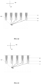
FIG. 1 shows a design of a semiconductor device in the prior art; -
FIG. 2 shows a schematic structural view of a semiconductor device according to a first embodiment of the disclosure; -
FIG. 3 shows a schematic structural view of a semiconductor device according to a second embodiment of the disclosure; -
FIG. 4 shows a schematic structural view of a semiconductor device according to a third embodiment of the disclosure; -
FIG. 5 shows a schematic structural view of a semiconductor device according to a fourth embodiment of the disclosure; -
FIG. 6 shows a schematic structural view of a semiconductor device according to a fifth embodiment of the disclosure; -
FIG. 7 shows an example of a curve diagram of a relationship between a thickness of a gate oxide layer and a P-type well concentration of a P-type body layer of the semiconductor device according to an embodiment of the disclosure; -
FIG. 8 shows a flowchart of a method for manufacturing a semiconductor device according to a sixth embodiment of the disclosure; -
FIG. 9 shows a schematic structural view of the semiconductor device after a trench is formed according to the sixth embodiment of the disclosure; -
FIG. 10 shows a schematic structural view of the semiconductor device after the trench is filled with an oxide according to the sixth embodiment of the disclosure; -
FIG. 11 shows a schematic structural view of the semiconductor device after a first part of the gate oxide layer is formed in the trench according to the sixth embodiment of the disclosure; -
FIG. 12 shows a schematic structural view of the semiconductor device after a second part of the gate oxide layer is formed in the trench according to the sixth embodiment of the disclosure; -
FIG. 13 shows a schematic structural view of the semiconductor device after a side wall of the gate oxide layer is formed in the trench according to the sixth embodiment of the disclosure; -
FIG. 14 shows a schematic structural view of the semiconductor device after polysilicon is deposited in the etched oxide in the trench according to the sixth embodiment of the disclosure; -
FIG. 15 shows a schematic structural view of the semiconductor device after the polysilicon is etched according to the sixth embodiment of the disclosure; -
FIG. 16 shows a schematic structural view of the semiconductor device after a carrier storage layer and a first P-type body layer are sequentially formed by ion implantation and drive-in according to the sixth embodiment of the disclosure; -
FIG. 17 shows a schematic structural view of the semiconductor device after an N-type source region is formed according to the sixth embodiment of the disclosure; and -
FIG. 18 shows a schematic structural view of the semiconductor device according to the sixth embodiment of the disclosure. - The disclosure will be described below by way of example with reference to the accompanying drawings. The following description discloses or shows various objectives, features and aspects of the disclosure. It can be understood by those skilled in the art that the following discussion is only for describing exemplary embodiments, and is not intended to limit the broader aspects of the disclosure embodied in exemplary constructions. Table 1 is a list of components and corresponding reference numerals in the accompanying drawings, where the same or similar reference numerals denote the same or similar components in the accompanying drawings. Therefore, once a component is defined in one embodiment, further definition and explanation may be omitted in other embodiments.
Table 1 Reference numeral Component name 1 Semiconductor device 10 Semiconductor layer 110; 210; 310; 410; 510; 610 Source region 111; 211; 311; 411; 511; 611 N-type source region P12; 112; 212; 312; 412; 512; 612 First P-type body layer 113; 213; 313; 413; 513 Carrier storage layer 114; 214; 314; 414; 514; 614 Top of N-type source region 120; 220; 320; 420; 520; 620 Gate region 121; 221; 321; 421; 521; 621 Gate oxide layer 122; 222; 322; 422; 522; 622 Polysilicon P23; 123; 223; 323; 423; 523; 623 Start point of increase in thickness of gate oxide layer 124; 224 Bottom of polysilicon 131; 231; 431; 631 Second P-type body layer 132; 232; 332; 432; 532; 632 Inter layer dielectric 133; 233; 333; 433; 533; 633 N-type drift layer 134; 234; 334; 434; 534; 634 Buffer layer 135; 235; 335; 435; 535; 635 P emitter layer 20 Top surface metal layer 21 First part of top surface metal layer 22 Second part of top surface metal layer 30 Bottom surface metal layer S1 First surface S2 Second surface D1 First direction D2 Second direction h1 First depth h2 Second depth h3 Third depth - In the description of this disclosure, it should be noted that the orientation or position relationship indicated by the terms "top", "bottom", "up", "down", "left", "right", "inside" and "outside" is the orientation or position relationship based on the accompanying drawings, or the orientation or position relationship that products are usually placed in use, and is intended only to facilitate the description of the disclosure and simplicity of the description and not to indicate or imply that the apparatus or element referred to must have a specific orientation or be constructed and operated in a specific orientation, so it cannot be understood as limiting the disclosure. Certainly, when the semiconductor device is installed in a circuit, the position relationship between the components is based on the actual orientation.
- In addition, in the description of the disclosure, unless otherwise specified, the expression of the singular form may include the plural concept.
- In addition, the terms "first", "second" and the like are only used for descriptive purposes, and should not be understood as indicating or implying relative importance or sequence.
- Besides, it should be noted that the features in the embodiments of the disclosure can be arbitrarily combined with each other in case of no conflict.
-
FIG. 2 to FIG. 6 show asemiconductor device 1 according to different embodiments of the disclosure. Thesemiconductor device 1 includes asemiconductor layer 10. Thesemiconductor layer 10 has a first surface S1 and a second surface S2 opposite to each other. Thesemiconductor layer 10 includes a source region (110; 210; 310; 410; 510) and a plurality of gate regions (120; 220; 320; 420; 520). - The source region (110; 210; 310; 410; 510) includes an N-type source region (111; 211; 311; 411; 511), a first P-type body layer (112; 212; 312; 412; 512) and a carrier storage layer (113; 213; 313; 413; 513) stacked along a first direction D1 (i.e., a downward direction in the drawings) pointing from the first surface S1 to the second surface S2. In other words, the N-type source region (111; 211; 311; 411; 511), the first P-type body layer (112; 212; 312; 412; 512) and the carrier storage layer (113; 213; 313; 413; 513) are sequentially stacked from top to bottom along the first direction D1.
- The plurality of gate regions (120; 220; 320; 420; 520) are arranged along a second direction D2 (i.e., a transverse direction in the drawings) perpendicular to the first direction D1. Each gate region (120; 220; 320; 420; 520) includes a gate oxide layer (121; 221; 321; 421; 521) and polysilicon (122; 222; 322; 422; 522). A side wall and a bottom (124; 224) of the polysilicon are surrounded by the gate oxide layer (121; 221; 321; 421; 521).
- The source region (110; 210; 310; 410; 510) is arranged between the adjacent two of the plurality of gate regions (120; 220; 320; 420; 520) in the second direction D2, and contacts the gate oxide layers (121; 221; 321; 421; 521) of the adjacent two gate regions along the second direction D2. In other words, the source region (110; 210; 310; 410; 510) is arranged between the adjacent two gate regions in the transverse direction.
- In each gate region (120; 220; 320; 420; 520), with respect to the first surface S1, the gate oxide layer (121; 221; 321; 421; 521) extends along the first direction D1 from a depth where a top (114; 214; 314; 414; 514) of the N-type source region (111; 211; 311; 411; 511) is located to a first depth h1. The bottom (124; 224) of the polysilicon is away from the first surface S1 and is located at a second depth h2 with respect to the first surface S1. A part of the gate oxide layer (121; 221; 321; 421; 521) from a top of the gate oxide layer to a third depth h3 has a constant thickness in the second direction. Third depth h3<second depth h2<first depth h1. A part of the gate oxide layer (121; 221; 321; 421; 521) from the third depth h3 to the second depth h2 has a gradually increasing thickness in the second direction D2. In other words, in the first direction D1, the top of the gate oxide layer (121; 221; 321; 421; 521) (i.e., the top of the polysilicon), the third depth h3 (i.e., the start point of the increase in thickness of the gate oxide layer (123; 223; 323; 423; 523)), the second depth h2 (i.e., the bottom of the polysilicon) and the first depth h1 (i.e., the bottom of the gate oxide layer) are sequentially arranged from top to bottom. The thickness of the gate oxide layer (121; 221; 321; 421; 521) in the transverse direction gradually increases downward from the third depth h3 (at least to the second depth h2). The third depth h3 is within a range of a depth where the first P-type body layer is located. In other words, the depth of the start point of the increase in thickness of the gate oxide layer is located between the depth where the top of the first P-type body layer (112; 212; 312; 412; 512) (the bottom of the N-type source region) is located and the depth where the bottom of the first P-type body layer (112; 212; 312; 412; 512) (the top of the carrier storage layer) is located. That is, the start point of the increase in thickness of the gate oxide layer overlaps with a transverse projection of the first P-type body layer. In the range of the depth where the first P-type body layer (112; 212; 312; 412; 512) is located, the thickness of the gate oxide layer influences the gate-emitter capacitance Cge. Based on this, the gate-emitter capacitance Cge of the semiconductor device of the disclosure is changed by gradually increasing the thickness of the gate oxide layer.
- By means of the above design, the semiconductor device of the disclosure has the following advantages: The gate-collector capacitance Cgc and the gate-emitter capacitance Cge of the semiconductor device can be adjusted at the same time, so that the reverse transfer capacitance Crss and the input capacitance Ciss can be adjusted at the same time, thereby stabilizing the threshold voltage of the semiconductor device and obtaining better didt and dvdt control abilities at switching transients.
- According to an embodiment of the disclosure, for each gate region (120; 220; 320; 420; 520), a thickness of the gate oxide layer (121; 221; 321; 421; 521) in the second direction D2 at any depth hx within a depth range from the third depth h3 to the second depth h2 may be a function of a P-type well concentration Na of the first P-type body layer (112; 212; 312; 412; 512) at the depth hx. In other words, at any depth hx within the depth range from the third depth h3 to the second depth h2, the thickness of the gate oxide layer in the transverse direction depends on the P-type well concentration Na of the first P-type body layer (112; 212; 312; 412; 512) at the depth hx.
- As described above, the thickness of the gate oxide layer influences the gate-emitter capacitance Cge and the gate-collector capacitance Cgc. By means of the above design, according to the semiconductor device of the disclosure, the thickness of the gate oxide layer among the influencing factors of the threshold voltage is correlated with the P-type well concentration Na , so that the threshold voltage can be always determined by the P-type well concentration Na , thereby stabilizing the threshold voltage of the semiconductor device and reducing the complexity of design and manufacturing.
- According to an embodiment of the disclosure, for each gate region, the thickness Tox of the gate oxide layer (121; 221; 321; 421; 521) in the second direction at any depth hx within the depth range from the third depth h3 to the second depth h2 and the P-type well concentration Na of the first P-type body layer (112; 212; 312; 412; 512) at the depth hx satisfies the following formula:

where K is a Boltzmann constant, T is an absolute temperature, Ni is a concentration of intrinsic carriers of the first P-type body layer at the depth hx, ε0 is a vacuum permittivity, εs is a relative permittivity of silicon, εox is a relative permittivity of the gate oxide layer, and V th_1 is a preset constant. For example, when the threshold voltage Vth of the semiconductor device is 5V, V th_1 may be set to 4 V to 4.2 V. By means of the above design, while the thickness Tox of the gate oxide layer is determined by the P-type well concentration Na , the influence of the change in thickness Tox of the oxide on the threshold voltage of the semiconductor device is less than the influence caused by the decrease in the P-type well concentration Na . - For example,
FIG. 7 shows an example of a curve diagram of the relationship between the thickness Tox of the gate oxide layer and the P-type well concentration Na of the first P-type body layer of the semiconductor device according to an embodiment of the disclosure.FIG. 7 shows the variation values (the coordinate axis on the left and multiple solid curves) of the P-type well concentration Na of the first P-type body layer at different depths under different working conditions (the annealing temperature is 1150°C, and the annealing time is 25 minutes/120 minutes/200 minutes (25M/120M/200M)), and also shows the variation ranges (the coordinate axis on the right and multiple dashed curves) of the thickness Tox of the oxide calculated according toFormula 1 based on the P-type well concentration Na of the first P-type body layer under different working conditions described above. In this example, the depth of the trench where the gate oxide layer of the gate region is located is 1.8 µm to 2.0 µm. According to needs, the depth of the trench may be other values, which is not limited here. The P-type well concentration Na (solid lines) of the first P-type body layer continuously decreases after the depth 0.5 µm shown by the horizontal axis. Therefore, the thickness Tox of the gate oxide layer continuously increases to adapt to the variation of the P-type well concentration Na , and is preferably not higher than the curve shown by the dashed line (obtained according to Formula 1).Table 2 Vth_1 4.18 V 4.15 V 4.12 V 4.17 V Thickness of gate oxide layer 1200 A 2050 A 4700 A 5800 A Depth 0.50 µm 1.50 µm 2 µm 2.80 µm P-type well concentration Na 1.20E+17 4.00E+16 9.00E+15 1.27E+14 - For example, Table 2 shows the values of the thickness Tox of the oxide varied depending on the P-type well concentration Na of the first P-type body layer based on
Formula 1 at different depths when the constant V th_1 is set within the range of 4 V to 4.2 V. - According to the embodiments of the disclosure, as shown in
FIG. 2 , along the first direction D1, the second depth h2 may be within a range of a depth where thecarrier storage layer 113 is located. In other words, thebottom 124 of thepolysilicon 122 may be within the range of the depth where thecarrier storage layer 113 is located. - According to the embodiments of the disclosure, as shown in
FIG. 3 , along the first direction D1, the second depth h2 may exceed the range of the depth where thecarrier storage layer 213 is located. In other words, thebottom 224 of thepolysilicon 222 may exceed the range of the depth where thecarrier storage layer 213 is located. - According to the embodiments of the disclosure, as shown in
FIG. 2 ,FIG. 3 andFIG. 5 , for each gate region (120; 220; 420), in the second direction D2, the part of the gate oxide layer (121; 221; 421) from the third depth h3 to the second depth h2 may have the gradually increasing thickness on both sides along the second direction D2. In other words, the thicknesses of both side walls of the gate oxide layer (121; 221; 421) respectively contacting two side surfaces of the polysilicon gradually increase. By means of the above design, the thickness of the gate oxide layer can increase smoothly, and it is also easy for the formation of the gate oxide layer. - According to the embodiments of the disclosure, as shown in
FIG. 4 andFIG. 6 , for each gate region (320; 520), in the second direction D2, the part of the gate oxide layer (321; 521) from the third depth h3 to the second depth h2 may have the gradually increasing thickness only on a side close to the source region (310; 510). - According to the embodiments of the disclosure, as shown in
FIG. 4 , for eachgate region 320, in the second direction D2, a side of a part of thegate oxide layer 321 from the first surface S1 to the third depth h3 away from thesource region 310 is exposed to an outside of the semiconductor device along the second direction D2. - According to the embodiments of the disclosure, as shown in
FIG. 2 ,FIG. 3 andFIG. 5 , thesemiconductor layer 10 may further include a second P-type body layer (131; 231; 431). The second P-type body layer (131; 231; 431) extends along the first direction D1 from the depth where the top (114; 214; 414) of the N-type source region (111; 211; 411) is located, and the second P-type body layer (131; 231; 431) contacts the gate oxide layer (121; 221; 421) of the adjacent gate region (120; 220; 420) along the second direction D2. In some embodiments, as shown inFIG. 5 , the second P-type body layer 431 surrounds the bottom of thegate oxide layer 421 of theadjacent gate region 420. - According to the embodiments of the disclosure, as shown in
FIG. 6 , at least one gate region in the plurality ofgate regions 520 may include onegate oxide layer 521 and two pieces ofpolysilicon 522. The two pieces ofpolysilicon 522 are arranged along the second direction D2 perpendicular to the first direction D1 in thegate oxide layer 521. It should be noted that the distance between the two pieces of polysilicon in one gate oxide layer meets the requirement of not interfering with each other. - According to the embodiments of the disclosure, the
semiconductor device 1 may be a trench IGBT unit. - According to the embodiments of the disclosure, the N-type source region may be an N+ source region.
- According to the embodiments of the disclosure, as shown in
FIG. 2 to FIG. 6 , thesemiconductor layer 10 may further include an N-type drift layer 133, abuffer layer 134 and anemitter layer 135. - According to the embodiments of the disclosure, as shown in
FIG. 2 to FIG. 6 , thesemiconductor layer 10 further includes an inter layer dielectric (ILD) (132; 432) extending along the first direction from the first surface. The inter layer dielectric may be an oxide layer. The inter layer dielectric (132; 432) contacts a top (114; 414) of the N-type source region (111; 411), and a top of the gate oxide layer (121; 421) and a top of the polysilicon (122; 422) in each gate region (120; 420) along the first direction D1. - According to the embodiments of the disclosure, as shown in
FIG. 2 to FIG. 6 , the semiconductor device further includes a topsurface metal layer 20. The topsurface metal layer 20 includes afirst part 21 arranged on theinter layer dielectric 132 and asecond part 22 extending from a bottom surface of the first part along the first direction through theinter layer dielectric 132 and the N-type source region 111 to contact the first P-type body layer 121. - According to the embodiments of the disclosure, as shown in
FIG. 2 to FIG. 6 , thesemiconductor device 1 further includes a bottomsurface metal layer 30. The bottomsurface metal layer 30 is arranged to cover the second surface S2 of thesemiconductor layer 10 along a direction opposite to the first direction D1. - According to the embodiments of the disclosure, a threshold voltage Vth of the
semiconductor device 1 is:
where θms is a metal-semiconductor work function difference, k is a Boltzmann constant, T is an absolute temperature, q is a charge, Qm is a charge in an equivalent metal, Qss is an equivalent surface state charge, Qfc is an equivalent fixed charge, and Cox is a capacitance of the oxide layer. - According to the embodiments of the disclosure, at least one gate region in the plurality of gate regions may be only adjacent to the second P-type body layer but not adjacent to the N-type source region. In other words, the gate oxide layer of the at least one gate region contacts the adjacent second P-type body layer along the second direction.
- In some embodiments, gate regions adjacent to the N-type source region in the plurality of gate regions are active gate regions, and gate regions adjacent to the second P-type body layer but not adjacent to the N-type source region in the plurality of gate regions are passive gate regions. The passive gate regions and the active gate regions are arranged in a preset number proportion in the semiconductor device so as to obtain better didt and dvdt control abilities at switching transients. As shown in
FIG. 2 andFIG. 3 , the number proportion of the passive gate regions to the active gate regions may be 1:2. It should be noted that the lower the proportion of the number of the active gate regions to the number of all the gate regions, the higher the didt and dvdt of the semiconductor device; and the higher the proportion, the lower the didt and dvdt of the semiconductor device. In some embodiments, the passive gate regions may be called dummy gate regions. In some embodiments, the passive gate regions may be called grounded gate regions. - The embodiments of the disclosure will be described in detail below.
-
FIG. 2 shows asemiconductor device 1 according to the first embodiment of the disclosure. Thesemiconductor device 1 is a trench IGBT unit. As shown inFIG. 2 , thesemiconductor device 1 includes asemiconductor layer 10, a topsurface metal layer 20 and a bottomsurface metal layer 30. - The
semiconductor layer 10 has a first surface S1 and a second surface S2 opposite to each other. Thesemiconductor layer 10 includes twosource regions 110, sixgate regions 120, three second P-type body layers 131, aninter layer dielectric 132, an N-type drift layer 133, abuffer layer 134 and anemitter layer 135. - Each
source region 110 includes an N-type source region 111, a first P-type body layer 112 and acarrier storage layer 113 stacked along a first direction D1 pointing from the first surface S1 to the second surface S2. The N-type source region is an N+ source region. - The six
gate regions 120 are arranged along a second direction D2 perpendicular to the first direction D1. Eachgate region 120 includes agate oxide layer 121 andpolysilicon 122. A side wall and abottom 124 of thepolysilicon 122 are surrounded by thegate oxide layer 121. - Each
source region 110 is arranged between the adjacent two of the sixgate regions 120 in the second direction D2, and contacts the gate oxide layers 121, 221 of the adjacent two gate regions along the second direction D2. - In each
gate region 120, with respect to the first surface S1, thegate oxide layer 121 extends along the first direction D1 from a depth where a top 114 of the N-type source region 111 is located to a first depth h1. Thebottom 124 of the polysilicon is away from the first surface S1 and is located at a second depth h2 with respect to the first surface S1. A part of thegate oxide layer 121 from a top of the gate oxide layer to the third depth h3 has a constant thickness in the second direction. Third depth h3<second depth h2<first depth h1. A part of thegate oxide layer 121 from the third depth h3 to the second depth h2 has a gradually increasing thickness in the second direction D2. The third depth h3 is within a range of a depth where the first P-type body layer 112 is located. Along the first direction D1, the second depth h2 may be within a range of a depth where thecarrier storage layer 113 is located. - For each
gate region 120, the thickness of thegate oxide layer 121 in the second direction D2 at any depth hx within the depth range from the third depth h3 to the second depth h2 and the P-type well concentration Na of the first P-type body layer 112 at the depth hx may satisfyFormula 1. - For each
gate region 120, in the second direction D2, the part of thegate oxide layer 121 from the third depth h3 to the second depth h2 has the gradually increasing thickness on both sides along the second direction D2. - The second P-
type body layer 131 extends along the first direction D1 from the depth where the top 114 of the N-type source region 111 is located, and the second P-type body layer 131 contacts thegate oxide layer 121 of theadjacent gate region 120 along the second direction D2. - In the six
gate regions 120 arranged along the second direction D2, gate regions 120 (i.e., the first, second, fifth and sixth gate regions from the left inFIG. 2 ) adjacent to the N-type source region 111 are active gate regions, and gate regions 120 (i.e., the third and fourth gate regions from the left) adjacent to the second P-type body layer 131 but not adjacent to the N-type source region 111 are passive gate regions. The passive gate regions and the active gate regions are arranged in a preset number proportion of 1:2 in thesemiconductor device 1. - The
inter layer dielectric 132 extends along the first direction from the first surface. The inter layer dielectric is an oxide layer. The inter layer dielectric 132 contacts a top 114 of the N-type source region 111, and a top of thegate oxide layer 121 and a top of thepolysilicon 122 in eachgate region 120 along the first direction D1. - The top
surface metal layer 20 includes afirst part 21 arranged on theinter layer dielectric 132 and asecond part 22 extending from a bottom surface of the first part along the first direction through theinter layer dielectric 132 and the N-type source region 111 to contact the first P-type body layer 121. - The bottom
surface metal layer 30 is arranged to cover the second surface S2 of thesemiconductor layer 10 along a direction opposite to the first direction D1. - The first embodiment of the disclosure has been described above in conjunction with the accompanying drawings. In the following description of other embodiments, components corresponding to or having the same function as those in the first embodiment will be denoted by the same or similar reference numerals, and descriptions of some components, operations and effects may be omitted to avoid repetition.
-
FIG. 3 shows asemiconductor device 1 according to the second embodiment of the disclosure. Thesemiconductor device 1 of the second embodiment is different from the first embodiment in that along the first direction D1, the second depth h2 exceeds the range of the depth where thecarrier storage layer 213 is located (closer to the second surface S2). -
FIG. 4 shows asemiconductor device 1 according to the third embodiment of the disclosure. The semiconductor layer of thesemiconductor device 1 has onesource region 310 and twogate regions 320. For eachgate region 320, in the second direction D2, the part of thegate oxide layer 321 from the third depth h3 to the second depth h2 may have the gradually increasing thickness only on a side close to thesource region 310 and have a basically constant thickness on the other side. - In addition, for each
gate region 320, in the second direction D2, a side of a part of thegate oxide layer 321 from the first surface S1 to the third depth h3 away from thesource region 310 is exposed to an outside of the semiconductor device along the second direction D2. - As shown in
FIG. 4 , thesemiconductor device 1 of the third embodiment does not include the second P-type body layer, and the twogate regions 320 are both active gate regions. -
FIG. 5 shows asemiconductor device 1 according to the fourth embodiment of the disclosure. Thesemiconductor device 1 of the fourth embodiment is different from the first embodiment in that the second P-type body layer 431 surrounds the bottom of thegate oxide layer 421 of theadjacent gate region 420. -
FIG. 6 shows asemiconductor device 1 according to the fifth embodiment of the disclosure. Thesemiconductor device 1 of the fifth embodiment is different from the first embodiment in that for eachgate region 520, in the second direction D2, the part of thegate oxide layer 521 from the third depth h3 to the second depth h2 has the gradually increasing thickness only on a side close to thesource region 510. - At least one gate region (the gate region in the middle in
FIG. 6 ) in the plurality ofgate regions 520 includes onegate oxide layer 521 and two pieces ofpolysilicon 522. The two pieces ofpolysilicon 522 are arranged along the second direction D2 perpendicular to the first direction D1 in thegate oxide layer 521. - An embodiment of the disclosure further provides a method for manufacturing the semiconductor device described above. Referring to
FIG. 8 , the method includes the following steps S10 to S60. - Step S10: Provide a semiconductor substrate layer.
- A material of the semiconductor substrate layer may be an N-type semiconductor material or a P-type semiconductor material. The main doping types of the N-type and P-type semiconductor materials may be phosphorus (Group V) and boron (Group III).
- Step S20: Form a plurality of trenches in the semiconductor substrate layer by etching.
- A bottom of the trench will correspond to a bottom of the gate oxide layer, so each trench is etched along a first direction to a position corresponding to a first depth h1.
- Here, chemical vapor deposition (CVD) may be used to deposit an oxide layer on the surface of the semiconductor layer as a mask layer used during the trench etching. As an alternative, a photoresist may be used as a mask layer during the trench etching.
- Step S30: Fill each trench with an oxide.
- Here, the oxide may be silicon dioxide (SiO2), silicon oxynitride (SiON), silicon oxycarbonitride (SiOCN), etc.
- Step S40: Form a gate oxide layer in each trench.
- The gate oxide layer may be formed by etching, etching+oxide addition, etc. The formed gate oxide layer has the shape and properties as disclosed in the above embodiments.
- Step S50: Deposit polysilicon in the etched oxide in each trench.
- Step S60: Etch the polysilicon to form a plurality of gate regions.
- Optionally, during the polysilicon etching, the adjacent gate oxide layer (or other oxides) may be etched together such that the tops of the polysilicon and the gate oxide layer are flush.
- In some embodiments, the forming the gate oxide layer in each trench in step S40 includes: etching the oxide to a position corresponding to a third depth h3, and etching the oxide from the third depth h3 to a position corresponding to a second depth h2. In some embodiments, isotropic dry etching is performed on the oxide to the position corresponding to the third depth h3. In some embodiments, anisotropic dry etching is performed on the oxide from the third depth h3 to the position corresponding to the second depth h2.
- In some embodiments, the filling each trench with the oxide in step S30 includes: etching the oxide while filling each trench with the oxide to form a notch (e.g., a notch with a triangular longitudinal section) on the oxide. In some embodiments, the oxide is etched with an etching gas containing carbon or fluorine (C/F). In some embodiments, the trench is filled with the oxide by depositing SiH4+
N 20/O2 or TEOS[Si(OC2H5)4]+O2/O3. In some embodiments, a depth-width ratio of the notch (especially the triangular notch) may be adjusted by adjusting the ratio of C/F contained in the depositing gas and the etching gas. - In some embodiments, the forming the gate oxide layer in each trench in step S40 includes: performing isotropic dry etching on the oxide with the notch to form the gate oxide layer.
- In some embodiments, the forming the gate oxide layer in each trench in step S40 includes: etching the oxide to the position corresponding to the second depth h2, and filling each trench with the oxide from the second depth h2 while reserving a required space for the polysilicon to the position corresponding to the third depth h3.
- In some embodiments, the forming the gate oxide layer in each trench in step S40 further includes: filling each trench with an additional oxide to form a side wall of the gate oxide layer after the oxide is etched from the third depth h3 to the position corresponding to the second depth h2.
- In some embodiments, the method further includes: forming a source region in the semiconductor substrate layer.
- It should be noted that the step of forming the source region in the semiconductor substrate layer may be implemented between any steps after step S10, or may be divided into several substeps which are implemented between different sets of steps.
- In some embodiments, the step of forming the source region in the semiconductor substrate layer includes: after etching the polysilicon to form the plurality of gate regions in step S60, sequentially forming the first P-type body layer and a carrier storage layer by ion implantation and drive-in from a side of the first surface of the semiconductor substrate layer; and forming an N-type source region in the first P-type body layer along a direction opposite to the first direction.
- In some embodiments, the step of forming the source region in the semiconductor substrate layer includes: before forming the plurality of trenches in the semiconductor substrate layer in step S20, forming the carrier storage layer on the semiconductor substrate layer.
- In some embodiments, the method further includes: forming an inter layer dielectric covering the plurality of gate regions and the source region by depositing an oxide, a top surface of the inter layer dielectric being the first surface of the semiconductor layer.
- In some embodiments, the method further includes:
- forming a contact hole at a position corresponding to the source region, the contact hole extending from the top surface of the inter layer dielectric along the first direction through the inter layer dielectric and the N-type source region to the first P-type body layer;
- forming a top surface metal layer on the top surface of the inter layer dielectric and in the contact hole; and
- forming a bottom surface metal layer on a side of a second surface of the semiconductor substrate layer.
- The method embodiment of the disclosure will be described in detail below.
-
FIG. 9 to FIG. 18 are specific steps of the sixth embodiment. - A semiconductor substrate layer is provided.
- A carrier storage layer is formed on the semiconductor substrate layer. It should be noted that the carrier storage layer is not shown in the drawings for the sake of brevity.
- A plurality of trenches are formed in the semiconductor substrate layer by etching such that each trench is configured to extend from a side of a first surface of the semiconductor substrate layer along a first direction D1 to a position corresponding to a first depth h1. The structure after this step is shown in
FIG. 9 . - Each trench is filled with an oxide. The structure after this step is shown in
FIG. 10 . - A
gate oxide layer 621 is formed in each trench, which includes the following steps: - Isotropic dry etching is performed on the oxide to a position corresponding to a third depth h3. The structure after this step is shown in
FIG. 11 . - Anisotropic dry etching is performed on the oxide from the third depth h3 to a position corresponding to a second depth h2. The structure after this step is shown in
FIG. 12 . - Each trench is filled with an additional oxide to form a side wall of the
gate oxide layer 621 after the oxide is etched from the third depth h3 to the position corresponding to the second depth h2. The structure after this step is shown inFIG. 13 . -
Polysilicon 622 is deposited in the etched oxide in each trench. The structure after this step is shown inFIG. 14 . - The
polysilicon 622 is etched to form a plurality ofgate regions 620. The structure after this step is shown inFIG. 15 . - A
source region 610 is formed in the semiconductor substrate layer, which includes the following steps: - A first P-
type body layer 612 and a second P-type body layer 631 are sequentially formed by ion implantation and drive-in from the side of the first surface of the semiconductor substrate layer. The structure after this step is shown inFIG. 16 . - An N-
type source region 611 is formed in the first P-type body layer 612 along a direction opposite to the first direction D1. The structure after this step is shown inFIG. 17 . - An inter layer dielectric 632 covering the plurality of
gate regions 620 and thesource region 610 are formed by depositing an oxide. A top surface of theinter layer dielectric 632 is the first surface S1 of the semiconductor layer. - A
buffer layer 634 and a P-type emitter layer 635 are formed along the first direction D1 on a side of the semiconductor substrate layer away from the first surface of the trench. A bottom surface of the P-type emitter layer 635 is a second surface S2 of the semiconductor layer. - A contact hole is formed at a position corresponding to the source region. The contact hole extends from the top surface of the
inter layer dielectric 632 along the first direction D1 through theinter layer dielectric 632 and the N-type source region 611 to the first P-type body layer 612. - A top
surface metal layer 20 is formed on the top surface of theinter layer dielectric 632 and in the contact hole. - A bottom
surface metal layer 30 is formed on a side of the second surface of the semiconductor substrate layer. The structure after this step is shown inFIG. 18 . - Although the preferred embodiments of the disclosure have been described in detail above, the disclosure is not limited thereto, and those skilled in the art can make various modifications and variations to the embodiments within the scope of the disclosure.
- For example, at least one gate region (the 3rd and 4th gate regions from the left in
FIG. 2 ) in the plurality ofgate regions 120 may be only adjacent to the second P-type body layer but not adjacent to the N-type source region. The at least one gate region is a dummy gate region. The dummy gate regions may be provided in proportion to the gate regions of the adjacent source region. - Although the inventive subject matter has been disclosed in the context of certain preferred or illustrated embodiments and examples, those skilled in the art will understand that the subject matter of the disclosure extends beyond the specifically disclosed embodiments to other optional embodiments and/or uses of the disclosure as well as apparent modifications and equivalents of the disclosure. In addition, although several variations of the disclosed embodiments have been shown and described in detail, other modifications within the scope of the subject matter of the disclosure based on the disclosure will be apparent to those skilled in the art. It is also to be expected that various combinations or sub-combinations of specific features and aspects of the disclosed embodiments can be made and these combinations or sub-combinations shall still fall within the scope of the subject matter of the disclosure. Accordingly, it should be understood that various features and aspects of the disclosed embodiments can be combined with or substituted for each other to form different modes of the disclosed inventive subject matter. Therefore, the scope of the inventive subject matter disclosed herein is not intended to be limited by the above specifically disclosed embodiments, but should be determined only by reading the claims fairly.
Claims (18)
- A semiconductor device, comprising:
a semiconductor layer, having a first surface and a second surface opposite to each other, the semiconductor layer comprising:a source region, comprising an N-type source region, a first P-type body layer and a carrier storage layer stacked along a first direction pointing from the first surface to the second surface; anda plurality of gate regions, arranged along a second direction perpendicular to the first direction, each gate region comprising a gate oxide layer and polysilicon, and a side wall and a bottom of the polysilicon being surrounded by the gate oxide layer,wherein the source region is arranged between the adjacent two of the plurality of gate regions in the second direction, and contacts the gate oxide layers of the adjacent two gate regions along the second direction;wherein in each gate region,with respect to the first surface, the gate oxide layer extends along the first direction from a depth where a top of the N-type source region is located to a first depth h1;the bottom of the polysilicon is away from the first surface and is located at a second depth h2 with respect to the first surface;a part of the gate oxide layer from a top of the gate oxide layer to a third depth h3 has a constant thickness in the second direction, wherein h3<h2<h1;a part of the gate oxide layer from the third depth h3 to the second depth h2 has a gradually increasing thickness in the second direction; andthe third depth h3 is within a range of a depth where the first P-type body layer is located. - The semiconductor device according to claim 1, wherein for each gate region, a thickness of the gate oxide layer in the second direction at any depth hx within a depth range from the third depth h3 to the second depth h2 is a function of a P-type well concentration Na of the first P-type body layer at the depth hx.
- The semiconductor device according to claim 2, wherein for each gate region, the thickness Tox of the gate oxide layer in the second direction at any depth hx within the depth range from the third depth h3 to the second depth h2 and the P-type well concentration Na of the first P-type body layer at the depth hx satisfies the following formula:

- The semiconductor device according to claim 1, whereinalong the first direction, the second depth h2 is within a range of a depth where the carrier storage layer is located; oralong the first direction, the second depth h2 exceeds the range of the depth where the carrier storage layer is located.
- The semiconductor device according to claim 1, wherein for each gate region, in the second direction, the part of the gate oxide layer from the third depth h3 to the second depth h2 has the gradually increasing thickness on both sides along the second direction.
- The semiconductor device according to claim 1, wherein for each gate region, in the second direction, the part of the gate oxide layer from the third depth h3 to the second depth h2 has the gradually increasing thickness only on a side close to the source region.
- The semiconductor device according to claim 6, wherein for each gate region, in the second direction, a side of a part of the gate oxide layer from the first surface to the third depth h3 away from the source region is exposed to an outside of the semiconductor device along the second direction.
- The semiconductor device according to claim 1, wherein the semiconductor layer further comprises a second P-type body layer, the second P-type body layer extending along the first direction from the depth where the top of the N-type source region is located, and the second P-type body layer contacting the gate oxide layer of the adjacent gate region along the second direction.
- The semiconductor device according to claim 8, wherein gate regions adjacent to the N-type source region in the plurality of gate regions are active gate regions, and gate regions adjacent to the second P-type body layer but not adjacent to the N-type source region in the plurality of gate regions are passive gate regions, the passive gate regions and the active gate regions being arranged in a preset number proportion in the semiconductor device.
- The semiconductor device according to claim 1, wherein at least one gate region in the plurality of gate regions comprises one gate oxide layer and two pieces of polysilicon, the two pieces of polysilicon being arranged along the second direction in the gate oxide layer.
- The semiconductor device according to any one of claims 1 to 10, wherein the semiconductor device is a trench IGBT unit.
- A method for manufacturing the semiconductor device according to any one of claims 1 to 11, comprising:providing a semiconductor substrate layer;forming a plurality of trenches in the semiconductor substrate layer by etching such that each trench is configured to extend from a side of a first surface of the semiconductor substrate layer along a first direction to a position corresponding to the first depth h1;filling each trench with an oxide;forming a gate oxide layer in each trench;depositing polysilicon in the etched oxide in each trench; andetching the polysilicon to form a plurality of gate regions.
- The method according to claim 12, wherein the forming the gate oxide layer in each trench comprises:performing isotropic dry etching on the oxide to a position corresponding to the third depth h3, andperforming anisotropic dry etching on the oxide from the third depth h3 to a position corresponding to the second depth h2.
- The method according to claim 13, wherein the forming the gate oxide layer in each trench further comprises:
filling each trench with an additional oxide to form a side wall of the gate oxide layer after the oxide is etched from the third depth h3 to the position corresponding to the second depth h2. - The method according to claim 12, further comprising:
forming a source region in the semiconductor substrate layer. - The method according to claim 15, wherein the forming the source region in the semiconductor substrate layer comprises:sequentially forming the first P-type body layer and the carrier storage layer by ion implantation and drive-in from the side of the first surface of the semiconductor substrate layer; andforming an N-type source region in the first P-type body layer along a direction opposite to the first direction.
- The method according to claim 15 or 16, further comprising:
forming an inter layer dielectric covering the plurality of gate regions and the source region by depositing an oxide, a top surface of the inter layer dielectric being the first surface of the semiconductor layer. - The method according to claim 17, further comprising:forming a contact hole at a position corresponding to the source region, the contact hole extending from the top surface of the inter layer dielectric along the first direction through the inter layer dielectric and the N-type source region to the first P-type body layer;forming a top surface metal layer on the top surface of the inter layer dielectric and in the contact hole; andforming a bottom surface metal layer on a side of a second surface of the semiconductor substrate layer.
Applications Claiming Priority (1)
| Application Number | Priority Date | Filing Date | Title |
|---|---|---|---|
| CN202311422812.0A CN119947212A (en) | 2023-10-30 | 2023-10-30 | Semiconductor device and method for manufacturing the same |
Publications (1)
| Publication Number | Publication Date |
|---|---|
| EP4550972A1 true EP4550972A1 (en) | 2025-05-07 |
Family
ID=93335179
Family Applications (1)
| Application Number | Title | Priority Date | Filing Date |
|---|---|---|---|
| EP24209923.2A Pending EP4550972A1 (en) | 2023-10-30 | 2024-10-30 | Semiconductor device and method for manufacturing same |
Country Status (3)
| Country | Link |
|---|---|
| US (1) | US20250142853A1 (en) |
| EP (1) | EP4550972A1 (en) |
| CN (1) | CN119947212A (en) |
Citations (8)
| Publication number | Priority date | Publication date | Assignee | Title |
|---|---|---|---|---|
| US20020153558A1 (en) * | 2001-04-02 | 2002-10-24 | Toshiyuki Takemori | Semiconductor device and method for manufacturing the same |
| JP2012138567A (en) * | 2010-12-08 | 2012-07-19 | Denso Corp | Insulated gate type semiconductor device |
| JP2012216675A (en) * | 2011-03-31 | 2012-11-08 | Toyota Motor Corp | Semiconductor device and manufacturing method of the same |
| US9000514B2 (en) | 2009-08-31 | 2015-04-07 | Alpha And Omega Semiconductor Incorporated | Fabrication of trench DMOS device having thick bottom shielding oxide |
| US20150108568A1 (en) * | 2013-10-21 | 2015-04-23 | Vishay-Siliconix | Semiconductor structure with high energy dopant implantation |
| US20150346270A1 (en) * | 2012-10-09 | 2015-12-03 | Infineon Technologies Ag | Test method and test arrangement |
| CN109256417A (en) * | 2017-07-14 | 2019-01-22 | 富士电机株式会社 | Semiconductor device |
| EP4120360A1 (en) * | 2021-07-16 | 2023-01-18 | Hitachi Energy Switzerland AG | Power semiconductor device |
-
2023
- 2023-10-30 CN CN202311422812.0A patent/CN119947212A/en active Pending
-
2024
- 2024-10-30 EP EP24209923.2A patent/EP4550972A1/en active Pending
- 2024-10-30 US US18/931,169 patent/US20250142853A1/en active Pending
Patent Citations (8)
| Publication number | Priority date | Publication date | Assignee | Title |
|---|---|---|---|---|
| US20020153558A1 (en) * | 2001-04-02 | 2002-10-24 | Toshiyuki Takemori | Semiconductor device and method for manufacturing the same |
| US9000514B2 (en) | 2009-08-31 | 2015-04-07 | Alpha And Omega Semiconductor Incorporated | Fabrication of trench DMOS device having thick bottom shielding oxide |
| JP2012138567A (en) * | 2010-12-08 | 2012-07-19 | Denso Corp | Insulated gate type semiconductor device |
| JP2012216675A (en) * | 2011-03-31 | 2012-11-08 | Toyota Motor Corp | Semiconductor device and manufacturing method of the same |
| US20150346270A1 (en) * | 2012-10-09 | 2015-12-03 | Infineon Technologies Ag | Test method and test arrangement |
| US20150108568A1 (en) * | 2013-10-21 | 2015-04-23 | Vishay-Siliconix | Semiconductor structure with high energy dopant implantation |
| CN109256417A (en) * | 2017-07-14 | 2019-01-22 | 富士电机株式会社 | Semiconductor device |
| EP4120360A1 (en) * | 2021-07-16 | 2023-01-18 | Hitachi Energy Switzerland AG | Power semiconductor device |
Also Published As
| Publication number | Publication date |
|---|---|
| US20250142853A1 (en) | 2025-05-01 |
| CN119947212A (en) | 2025-05-06 |
Similar Documents
| Publication | Publication Date | Title |
|---|---|---|
| US9337283B2 (en) | Semiconductor device with field plate | |
| US10749006B2 (en) | Trench power transistor and method of producing the same | |
| US12113103B2 (en) | Charge-balance power device, and process for manufacturing the charge-balance power device | |
| US8129241B2 (en) | Method for forming a shielded gate trench FET | |
| TWI705503B (en) | Semiconductor structure and associated fabricating method | |
| EP1269530B1 (en) | Method of making a trench gate dmos transistor | |
| US7948028B2 (en) | DRAM device having a gate dielectric layer with multiple thicknesses | |
| US7816210B2 (en) | Method for producing a trench transistor and trench transistor | |
| US11069794B2 (en) | Trench power transistor and method of producing the same | |
| CN110828419B (en) | Integrated circuit device including a boron-containing insulating pattern | |
| US4992838A (en) | Vertical MOS transistor with threshold voltage adjustment | |
| US6104065A (en) | Semiconductor device having an active region in a substrate with trapezoidal cross-sectional structure | |
| US6373098B1 (en) | Trench-gated device having trench walls formed by selective epitaxial growth and process for forming device | |
| US20220293786A1 (en) | An improved shielded gate trench mosfet with low on-resistance | |
| US10700175B2 (en) | Shielded gate MOSFET and fabricating method thereof | |
| US20080211016A1 (en) | Trench mosgated device with deep trench between gate trenches | |
| US20190326389A1 (en) | Method Of Manufacturing A Deep Trench Super Junction MOSFET | |
| CN111128706B (en) | Manufacturing method of field oxide with gradually-changed thickness in groove and manufacturing method of SGT (super-stable Gate Bipolar transistor) device | |
| US9130033B2 (en) | Semiconductor device and method for fabricating the same | |
| US11929411B2 (en) | Recessed access devices and methods of forming a recessed access devices | |
| US20250142853A1 (en) | Semiconductor device and method for manufacturing same | |
| CN108695393B (en) | Semiconductor device including field electrode and gate electrode in trench structure and method of manufacture | |
| US9123814B2 (en) | Field effect device provided with a thinned counter-electrode and method for fabricating | |
| CN110867380B (en) | Method for forming semiconductor device | |
| US12295161B2 (en) | Trench isolation having three portions with different materials, and LDMOS FET including same |
Legal Events
| Date | Code | Title | Description |
|---|---|---|---|
| PUAI | Public reference made under article 153(3) epc to a published international application that has entered the european phase |
Free format text: ORIGINAL CODE: 0009012 |
|
| STAA | Information on the status of an ep patent application or granted ep patent |
Free format text: STATUS: THE APPLICATION HAS BEEN PUBLISHED |
|
| AK | Designated contracting states |
Kind code of ref document: A1 Designated state(s): AL AT BE BG CH CY CZ DE DK EE ES FI FR GB GR HR HU IE IS IT LI LT LU LV MC ME MK MT NL NO PL PT RO RS SE SI SK SM TR |
|
| STAA | Information on the status of an ep patent application or granted ep patent |
Free format text: STATUS: REQUEST FOR EXAMINATION WAS MADE |
|
| 17P | Request for examination filed |
Effective date: 20251107 |