EP4550742A1 - Austausch einer sanitäreinrichtung - Google Patents
Austausch einer sanitäreinrichtung Download PDFInfo
- Publication number
- EP4550742A1 EP4550742A1 EP23207167.0A EP23207167A EP4550742A1 EP 4550742 A1 EP4550742 A1 EP 4550742A1 EP 23207167 A EP23207167 A EP 23207167A EP 4550742 A1 EP4550742 A1 EP 4550742A1
- Authority
- EP
- European Patent Office
- Prior art keywords
- sanitary
- gateway
- facility
- type
- sanitary facility
- Prior art date
- Legal status (The legal status is an assumption and is not a legal conclusion. Google has not performed a legal analysis and makes no representation as to the accuracy of the status listed.)
- Granted
Links
Images


Classifications
-
- H—ELECTRICITY
- H04—ELECTRIC COMMUNICATION TECHNIQUE
- H04L—TRANSMISSION OF DIGITAL INFORMATION, e.g. TELEGRAPHIC COMMUNICATION
- H04L43/00—Arrangements for monitoring or testing data switching networks
- H04L43/08—Monitoring or testing based on specific metrics, e.g. QoS, energy consumption or environmental parameters
- H04L43/0805—Monitoring or testing based on specific metrics, e.g. QoS, energy consumption or environmental parameters by checking availability
- H04L43/0811—Monitoring or testing based on specific metrics, e.g. QoS, energy consumption or environmental parameters by checking availability by checking connectivity
-
- H—ELECTRICITY
- H04—ELECTRIC COMMUNICATION TECHNIQUE
- H04W—WIRELESS COMMUNICATION NETWORKS
- H04W36/00—Hand-off or reselection arrangements
- H04W36/34—Reselection control
- H04W36/38—Reselection control by fixed network equipment
-
- H—ELECTRICITY
- H04—ELECTRIC COMMUNICATION TECHNIQUE
- H04L—TRANSMISSION OF DIGITAL INFORMATION, e.g. TELEGRAPHIC COMMUNICATION
- H04L41/00—Arrangements for maintenance, administration or management of data switching networks, e.g. of packet switching networks
- H04L41/08—Configuration management of networks or network elements
- H04L41/0803—Configuration setting
- H04L41/0813—Configuration setting characterised by the conditions triggering a change of settings
- H04L41/0816—Configuration setting characterised by the conditions triggering a change of settings the condition being an adaptation, e.g. in response to network events
-
- H—ELECTRICITY
- H04—ELECTRIC COMMUNICATION TECHNIQUE
- H04L—TRANSMISSION OF DIGITAL INFORMATION, e.g. TELEGRAPHIC COMMUNICATION
- H04L41/00—Arrangements for maintenance, administration or management of data switching networks, e.g. of packet switching networks
- H04L41/08—Configuration management of networks or network elements
- H04L41/0803—Configuration setting
- H04L41/0813—Configuration setting characterised by the conditions triggering a change of settings
- H04L41/082—Configuration setting characterised by the conditions triggering a change of settings the condition being updates or upgrades of network functionality
-
- H—ELECTRICITY
- H04—ELECTRIC COMMUNICATION TECHNIQUE
- H04L—TRANSMISSION OF DIGITAL INFORMATION, e.g. TELEGRAPHIC COMMUNICATION
- H04L41/00—Arrangements for maintenance, administration or management of data switching networks, e.g. of packet switching networks
- H04L41/08—Configuration management of networks or network elements
- H04L41/0803—Configuration setting
- H04L41/084—Configuration by using pre-existing information, e.g. using templates or copying from other elements
- H04L41/0846—Configuration by using pre-existing information, e.g. using templates or copying from other elements based on copy from other elements
-
- H—ELECTRICITY
- H04—ELECTRIC COMMUNICATION TECHNIQUE
- H04L—TRANSMISSION OF DIGITAL INFORMATION, e.g. TELEGRAPHIC COMMUNICATION
- H04L41/00—Arrangements for maintenance, administration or management of data switching networks, e.g. of packet switching networks
- H04L41/08—Configuration management of networks or network elements
- H04L41/085—Retrieval of network configuration; Tracking network configuration history
- H04L41/0853—Retrieval of network configuration; Tracking network configuration history by actively collecting configuration information or by backing up configuration information
-
- H—ELECTRICITY
- H04—ELECTRIC COMMUNICATION TECHNIQUE
- H04L—TRANSMISSION OF DIGITAL INFORMATION, e.g. TELEGRAPHIC COMMUNICATION
- H04L67/00—Network arrangements or protocols for supporting network services or applications
- H04L67/01—Protocols
- H04L67/12—Protocols specially adapted for proprietary or special-purpose networking environments, e.g. medical networks, sensor networks, networks in vehicles or remote metering networks
- H04L67/125—Protocols specially adapted for proprietary or special-purpose networking environments, e.g. medical networks, sensor networks, networks in vehicles or remote metering networks involving control of end-device applications over a network
-
- H—ELECTRICITY
- H04—ELECTRIC COMMUNICATION TECHNIQUE
- H04W—WIRELESS COMMUNICATION NETWORKS
- H04W36/00—Hand-off or reselection arrangements
- H04W36/24—Reselection being triggered by specific parameters
- H04W36/30—Reselection being triggered by specific parameters by measured or perceived connection quality data
-
- H—ELECTRICITY
- H04—ELECTRIC COMMUNICATION TECHNIQUE
- H04W—WIRELESS COMMUNICATION NETWORKS
- H04W4/00—Services specially adapted for wireless communication networks; Facilities therefor
- H04W4/30—Services specially adapted for particular environments, situations or purposes
- H04W4/38—Services specially adapted for particular environments, situations or purposes for collecting sensor information
-
- A—HUMAN NECESSITIES
- A47—FURNITURE; DOMESTIC ARTICLES OR APPLIANCES; COFFEE MILLS; SPICE MILLS; SUCTION CLEANERS IN GENERAL
- A47K—SANITARY EQUIPMENT; ACCESSORIES THEREFOR, e.g. TOILET ACCESSORIES
- A47K4/00—Combinations of baths, showers, sinks, wash-basins, closets, or urinals, not covered by a single other group of this subclass
-
- H—ELECTRICITY
- H04—ELECTRIC COMMUNICATION TECHNIQUE
- H04L—TRANSMISSION OF DIGITAL INFORMATION, e.g. TELEGRAPHIC COMMUNICATION
- H04L67/00—Network arrangements or protocols for supporting network services or applications
- H04L67/01—Protocols
- H04L67/12—Protocols specially adapted for proprietary or special-purpose networking environments, e.g. medical networks, sensor networks, networks in vehicles or remote metering networks
-
- H—ELECTRICITY
- H04—ELECTRIC COMMUNICATION TECHNIQUE
- H04L—TRANSMISSION OF DIGITAL INFORMATION, e.g. TELEGRAPHIC COMMUNICATION
- H04L67/00—Network arrangements or protocols for supporting network services or applications
- H04L67/34—Network arrangements or protocols for supporting network services or applications involving the movement of software or configuration parameters
Definitions
- the present invention relates to a method for replacing a sanitary fixture.
- the present invention further relates to a gateway that carries out the method steps.
- Sanitary fixtures such as toilets, urinals, washbasin fittings, shower and bathtub fittings, hygienic flush valves, and the like are known from the prior art. These fixtures offer extended functionality and, for example, allow configuration regarding operating parameters to be used. For this purpose, the aforementioned sanitary fixtures include electronic controls through which this extended functionality is realized.
- a sanitary fixture needs to be replaced, this may also mean replacing the electronic control unit installed within it.
- This is problematic because the electronic control unit's memory stores values for the sanitary fixture's operating parameters, which must be retained for continued use even after the fixture has been replaced with a device of the same design or type. To date, such a configuration of a replaced sanitary fixture cannot be automatically transferred to a new sanitary fixture, especially without the use of third-party devices (such as the smartphone of a plumber or service technician).
- the object of the present invention is to provide a solution which enables a plumbing installer or service technician to continue to use an existing configuration for a sanitary facility acting as a replacement device without specific IT-related expertise, without access rights to a given system and without manually setting individual parameters.
- this object is achieved by a method for replacing a sanitary facility assigned to a gateway and communicatively connected thereto, comprising the following method steps carried out by the gateway: Obtaining and saving a configuration of the sanitary facility, Identifying that the sanitary facility is no longer communicatively connected to the gateway, Identifying a second sanitary facility which is not assigned to the gateway, determining a type of the second sanitary facility, comparing the type of the sanitary facility on the basis of the stored configuration with the determined type of the second sanitary facility, determining that the type of the sanitary facility and the type of the second sanitary facility match, and uploading the saved configuration of the sanitary facility to the second sanitary facility.
- the above solution is based on the realization that if the gateway automatically saves the configurations of all sanitary fixtures connected to a gateway, when a sanitary fixture containing a corresponding electronic control system is replaced, neither access rights to the system into which the sanitary fixture is integrated nor an additional, particularly manual, work step are required. This drastically reduces the demands on the personnel performing the replacement, as specialist knowledge regarding the reconfiguration of a sanitary fixture serving as a repair replacement is no longer required.
- the configuration of the sanitary facility is retained and saved when the facility was first assigned to the gateway. This ensures that a configuration of the facility is immediately available when it is initially integrated into an existing system.
- the configuration of the sanitary facility is retained and saved if at least one parameter of the configuration has been modified. This ensures that the gateway does not retain outdated information that could potentially be used for a replacement device.
- the at least one parameter has been modified by the gateway.
- the gateway itself initiates the availability of a correspondingly updated version of the configuration.
- the at least one parameter has been modified by a user device communicatively connected to the sanitary facility, in particular by an application of the same.
- a user device directly accesses the sanitary facility, e.g., via a wireless connection (such as Bluetooth).
- a wireless connection such as Bluetooth
- an assignment to the gateway is given if the sanitary facility is assigned a logical address, particularly within the framework of an initial enumeration Since a logical address of a sanitary facility is always assigned by the gateway, this serves as an indicator that an assignment has already taken place if a logical address of a sanitary facility exists.
- the method further comprises installing a firmware update on the second sanitary device and initiating a restart of the second sanitary device before installing the saved configuration on the second sanitary device.
- the sanitary fixture is a toilet, a shower toilet, a urinal, a washbasin fitting, a shower or bathtub fitting, an odor extractor, a hygiene flush, an electronic cistern actuator, a hygiene flush unit, a temperature sensor, a pressure sensor, a volume sensor, a mirror cabinet (which, for example, has functions related to ventilation, heating, surface heating, and/or facial or user recognition), a lighting device, or an electronic control system included in one of the aforementioned devices.
- the solution according to the invention allows for easy replacement of a single device. If the sanitary fixture is one of the aforementioned sensors, it can also be provided that such a sensor is connected directly to the gateway, thereby simplifying the identification of a communicative disconnection and the identification of a replacement device.
- the configuration preferably comprises a) product-specific parameters, in particular the type, physical location of the sanitary facility, position within an arrangement with other sanitary facilities, and assigned logical address; b) usage-specific parameters, in particular the number of days of use, the number of flushes, and the number of uses; and/or c) setting-specific parameters, in particular the flush time, follow-up time, interval flush interval, interval flush flush time, surge flush interval, surge flush flush time, and cleaning time.
- the color of a lighting fixture can also be provided as a setting-specific parameter if a sanitary facility includes one or itself represents one.
- a bus system particularly via EIA-485 or RS-485, is provided for the communicative connection between the gateway and the sanitary facility.
- the use of a bus system is advantageous because it allows for reliable communication.
- an intermediate converter is provided to establish a communicative connection between the gateway and the sanitary facility.
- Such a converter enables devices to have a simpler and therefore more cost-effective communication interface. Nevertheless, communication via the bus system is possible, as one converter can be connected to a large number of devices, for example, up to five.
- an Inter Device Connection is provided for the communicative connection between the converter and the sanitary facility.
- IDC Inter Device Connection
- the method further comprises issuing a notification upon detection that the type of sanitary facility and the type of the second sanitary facility do not match.
- the gateway itself can display such a notification on a display, issue an acoustic notification via a speaker of the gateway, or send a message, for example, by email, to an addressee stored in the gateway.
- provision can be made for a notification to be issued or displayed by a user device, in particular by means of an application thereof.
- a gateway comprising a processor, a memory and a communication unit, wherein the gateway is configured to obtain (i.e. in particular to receive) a configuration from a sanitary facility which is assigned to the gateway and communicatively connected thereto, to identify that the sanitary facility is no longer communicatively connected to the gateway, to identify a second sanitary facility which is not assigned to the gateway, to determine a type of the second sanitary facility, to compare the type of the sanitary facility on the basis of the stored configuration with the determined type of the second sanitary facility, to determine that the type of the sanitary facility and the type of the second sanitary facility match, and to load the stored configuration of the sanitary facility onto the second sanitary facility.
- the gateway and the sanitary fixture to be replaced are communicatively connected to one another exclusively via a radio connection (e.g., via Bluetooth).
- the method according to the invention can be carried out semi-automatically by using a second sanitary fixture after the sanitary fixture has been decommissioned.
- a plumber or service technician then presses a button provided on the gateway, which sets the gateway into a pairing process in which a connection can be established with new devices, such as the second sanitary fixture.
- a connection from the user device to the gateway is then established using an application provided on a user device, e.g., a smartphone, of the plumber or service technician.
- the application Without entering a password or other information, the application displays the second plumbing fixture, which has since been detected by the gateway, which is still in pairing mode. After selecting an appropriate function (e.g., "Terminal Replacement” or “Repair Replacement”), the plumber or service technician is prompted to enter a serial number for both the replaced plumbing fixture and the replacing plumbing fixture. This serial number is physically affixed to the respective plumbing fixture, for example, in the form of a sticker or similar. Using these serial numbers, the gateway ultimately uploads the configuration of the plumbing fixture to the second plumbing fixture.
- an appropriate function e.g., "Terminal Replacement” or "Repair Replacement”
- This serial number is physically affixed to the respective plumbing fixture, for example, in the form of a sticker or similar.
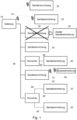
- Fig. 1 shows a schematic overview of a system comprising several sanitary facilities 20, which are communicatively connected to a gateway 10.
- a bus system 40 is provided for the connection.
- the sanitary facilities 20 are connected to the gateway 10 either directly via the bus system 40 or by means of a converter 50.
- a converter 50 itself acts as a participant in the communication bus, i.e., it is directly connected to the bus system 40, but additionally establishes a communicative connection to one or more sanitary facilities 20, in this case by means of an inter-device connection, for example, via an inter-integrated circuit (I 2 C).
- the gateway 10 has information about which sanitary facilities 20 can be reached via which converter 50, i.e., which converter is connected to it.
- sanitary facilities 20 can also be connected directly to the gateway 10, for which purpose a wireless connection 70, for example via Bluetooth, is provided.
- a wireless connection 70 for example via Bluetooth
- Such a connection of the sanitary facilities 20 is suitable if the local conditions do not allow the use of a connection via a bus system 40.
- a wireless connection 70 can be provided not only between the gateway 10 and sanitary facilities 20, but also between a sanitary facility 20 and a user device 30, which may be, for example, the smartphone of a plumber or service technician. This allows direct access to the sanitary facility 20, for example, to modify or read data from it.
- a sanitary facility 20 is no longer communicatively connected to the gateway 10, which is illustrated by the corresponding crossed-out element.
- the fact that a second sanitary facility 25, which is not yet assigned to the gateway 10, is intended to serve as a repair replacement is illustrated by the arrow shown next to it.
- Fig. 2 shows a flowchart of an embodiment of the method according to the invention.
- the method can be applied to a communication structure according to Fig. 1
- a sanitary facility 20 is assigned to a gateway 10 and communicatively connected to it.
- the gateway 10 receives a configuration of the sanitary facility 20 and saves it. This method step occurs, for example, if the sanitary facility 20 was assigned to the gateway 10 for the first time or if at least one parameter of the configuration of the sanitary facility 20 was modified.
- the at least one parameter can be modified by the gateway 10 or by a user device 30 communicatively connected to the sanitary facility 20, in particular via a wireless connection 70. Furthermore, it can also be provided that the gateway 10 receives and stores a configuration of the sanitary facility 20 at predefined intervals.
- method step 220 it is identified that the sanitary facility 20 is no longer communicatively connected to the gateway 10.
- the trigger for the end of a communicative connection can be, for example, that the sanitary facility 20 has been disconnected from the power supply.
- a second sanitary facility 25 is identified that is not, i.e., not yet, assigned to gateway 10.
- gateway 10 checks, for example, whether devices that have not yet been assigned a logical address are communicatively accessible. Assigning a logical address to sanitary facilities 20 can be performed, for example, as part of an initial enumeration.
- the gateway 10 determines a type of the second sanitary facility 25 that was previously identified.
- the determined type of the second sanitary facility 25 is compared in method step 250 with the type of the sanitary facility 20 that is no longer communicatively connected to the gateway 10. A comparison is possible because the gateway 10 has the configuration of this sanitary facility 20, which also includes the type of the latter.
- the gateway 10 determines in method step 260 that the type of sanitary facility 20 and the type of the second sanitary facility 25 match, the stored configuration of the sanitary facility 20 is uploaded to the second sanitary facility 25 in method step 270. In this way, for example, the logical address of the replaced sanitary facility 20 is adopted by the replacing second sanitary facility 25.
- Fig. 3 shows a flowchart of an exemplary embodiment for the optional execution of a firmware update within the scope of the method according to the invention.
- the sanitary facility 20 is first disconnected from the gateway 10, i.e., the sanitary facility 20 is no longer communicatively connected to the gateway 10.
- the second sanitary facility 25 is connected to the gateway 10. This includes, for example, establishing a power supply for the second sanitary facility 25 and connecting it via the bus system 40.
- the gateway 10 checks whether a firmware update is to be performed for the second sanitary facility 25. For this purpose, the gateway compares 10 compares the firmware version currently present on the second sanitary device 25 with the most recent firmware version known to the gateway 10. The gateway 10 can independently obtain information regarding the most recent firmware version for different types of sanitary devices, for example, via the Internet.
- a firmware update is necessary, this is performed in method step 340 by transmitting corresponding data from the gateway 10 to the second sanitary device 25, and the second sanitary device 25 receives a command to process this data. Subsequently, i.e., after the firmware update is completed, the second sanitary device 25 is restarted in method step 350.
- the gateway 10 initiates the restoration of the configuration on the second sanitary device 25.
- the gateway 10 determines in method step 330 that the firmware version present on the second sanitary device 25 already corresponds to the version considered current by the gateway 10, the method steps 340 and 350 are not carried out, but the configuration on the second sanitary device 25 is restored directly according to method step 360.
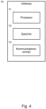
- Fig. 4 shows a schematic block diagram of an embodiment of a gateway 10 according to the invention.
- the gateway 10 has a processor 10, which controls operations of the gateway 10. Furthermore, the gateway 10 has one or more memories 12, which are used, on the one hand, to store an operating system of the gateway 10 and, on the other hand, to store configurations received from sanitary facilities 20. Furthermore, one or more communication units 13 are provided in the gateway 10. On the one hand, a connection via bus system 40 is possible, and on the other hand, a wireless connection 70, in particular to individual sanitary facilities 20, can be established.
Landscapes
- Engineering & Computer Science (AREA)
- Computer Networks & Wireless Communication (AREA)
- Signal Processing (AREA)
- Health & Medical Sciences (AREA)
- Computing Systems (AREA)
- General Health & Medical Sciences (AREA)
- Medical Informatics (AREA)
- Environmental & Geological Engineering (AREA)
- Selective Calling Equipment (AREA)
- Small-Scale Networks (AREA)
Abstract
Description
- Die vorliegende Erfindung betrifft ein Verfahren zum Austausch einer Sanitäreinrichtung. Gegenstand der vorliegenden Erfindung ist ferner ein die Verfahrensschritte ausführendes Gateway.
- Aus dem Stand der Technik sind Sanitäreinrichtungen wie Toiletten, Urinale, Waschtischarmaturen, Dusch- und Badewannenarmaturen, Hygienespülungen und dergleichen bekannt, welche eine erweiterte Funktionalität bieten und beispielsweise eine Konfiguration hinsichtlich zu verwendender Betriebsparameter erlauben. Zu diesem Zweck umfassen die vorgenannten Sanitäreinrichtungen elektronische Steuerungen, durch welche diese erweiterte Funktionalität realisiert wird.
- Sofern ein Austausch einer Sanitäreinrichtung erforderlich ist, kann dies zugleich bedeuten, dass eine darin verbaute elektronische Steuerung ebenfalls mit ausgetauscht wird. Dies ist problematisch, da im Speicher der elektronischen Steuerung Werte für Betriebsparameter für die Sanitäreinrichtung abgelegt sind, welche auch nach einem Austausch der Sanitäreinrichtung durch ein bau- oder typengleiches Gerät zwecks Weiternutzung vorhanden sein müssen. Bisher kann eine solche Konfiguration einer ausgetauschten Sanitäreinrichtung, insbesondere ohne den Einsatz von Drittgeräten (wie z.B. das Smartphone eines Sanitärinstallateurs oder Servicetechnikers), nicht automatisch auf eine neue Sanitäreinrichtung übertragen werden.
- Dies ist besonders nachteilig für den Fall eines eine Vielzahl von Sanitäreinrichtungen umfassenden vernetzten Systems, da ein den Austausch vornehmender Sanitärinstallateur oder Servicetechniker über einen Zugang zum System verfügen müsste, um eine Konfiguration auf die neue Sanitäreinrichtung, d.h. auf die elektronische Steuerung selbiger, übertragen zu können.
- Vor diesem Hintergrund liegt der vorliegenden Erfindung die Aufgabe zugrunde, eine Lösung bereitzustellen, welche es einem Sanitärinstallateur oder Servicetechniker ermöglicht, ohne spezifische IT-bezogene Fachkenntnisse, ohne Zugriffsrechte auf ein gegebenes System und ohne ein manuelles Einstellen einzelner Parameter eine bestehende Konfiguration für eine als Austauschgerät fungierende Sanitäreinrichtung weiterzuverwenden.
- Erfindungsgemäß wird diese Aufgabe gelöst durch ein Verfahren zum Austausch einer einem Gateway zugeordneten und kommunikativ mit diesem verbundenen Sanitäreinrichtung, umfassend die folgenden seitens des Gateways ausgeführten Verfahrensschritte: Erhalten und Abspeichern einer Konfiguration der Sanitäreinrichtung, Identifizieren, dass die Sanitäreinrichtung mit dem Gateway nicht mehr kommunikativ verbunden ist, Identifizieren einer zweiten Sanitäreinrichtung, welche dem Gateway nicht zugeordnet ist, Ermitteln eines Typs der zweiten Sanitäreinrichtung, Vergleichen des Typs der Sanitäreinrichtung auf Basis der abgespeicherten Konfiguration mit dem ermittelten Typ der zweiten Sanitäreinrichtung, Feststellen, dass der Typ der Sanitäreinrichtung und der Typ der zweiten Sanitäreinrichtung übereinstimmen, und Aufspielen der abgespeicherten Konfiguration der Sanitäreinrichtung auf die zweite Sanitäreinrichtung.
- Der vorstehenden Lösung liegt die Erkenntnis zu Grunde, dass bei automatischer Speicherung der Konfigurationen aller an ein Gateway angeschlossenen Sanitäreinrichtungen seitens des Gateways bei einem Austausch einer Sanitäreinrichtung, welche eine entsprechende elektronische Steuerung umfasst, weder Zugriffsrechte auf ein solches System, in welches die Sanitäreinrichtung eingebunden ist, noch ein zusätzlicher, insbesondere manueller, Arbeitsschritt erforderlich sind. Die Anforderungen an das einen Austausch vornehmende Personal können dadurch drastisch reduziert werden, da keine Fachkenntnisse hinsichtlich einer Neukonfiguration einer als Reparaturersatz fungierenden Sanitäreinrichtung mehr erforderlich sind.
- Vorteilhafterweise erfolgt das Erhalten und Abspeichern der Konfiguration der Sanitäreinrichtung, sofern die Sanitäreinrichtung erstmalig dem Gateway zugeordnet wurde. Auf diese Weise kann sichergestellt werden, dass bei initialem Einbinden einer Sanitäreinrichtung in ein bestehendes System unmittelbar eine Konfiguration selbiger vorliegt.
- Vorzugsweise erfolgt das Erhalten und Abspeichern der Konfiguration der Sanitäreinrichtung, sofern wenigstens ein Parameter der Konfiguration der Sanitäreinrichtung modifiziert wurde. Dadurch bleibt gewährleistet, dass seitens des Gateways keine veralteten Informationen vorliegen, welche mitunter für ein Ersatzgerät verwendet werden würden.
- In einer bevorzugten Ausgestaltung wurde der wenigstens eine Parameter seitens des Gateways modifiziert. Somit initiiert das Gateway selbst durch eine Konfigurationsänderung für die Sanitäreinrichtung, dass eine entsprechend aktualisierte Fassung der Konfiguration vorhanden ist.
- Vorteilhafterweise wurde der wenigstens eine Parameter seitens einer kommunikativ mit der Sanitäreinrichtung verbundenen Nutzereinrichtung, insbesondere seitens einer Applikation derselben, modifiziert. In einem solchen Szenario erfolgt beispielsweise ein direkter Zugriff einer Nutzereinrichtung, z.B. mittels einer drahtlosen Verbindung (wie Bluetooth), auf die Sanitäreinrichtung. Damit Änderungen an der Konfiguration vom Gateway zwecks Speicherung erfasst werden, kann ferner vorgesehen sein, dass das Gateway in vordefinierten Intervallen die Konfiguration der Sanitäreinrichtung abruft und speichert.
- Vorzugsweise ist eine Zuordnung zum Gateway gegeben, sofern der Sanitäreinrichtung, insbesondere im Rahmen einer initialen Enumeration, eine logische Adresse zugewiesen wurde. Da eine logische Adresse einer Sanitäreinrichtung stets seitens des Gateways zugewiesen wird, dient dies als Indikator dafür, dass bei vorhandener logischer Adresse einer Sanitäreinrichtung bereits eine Zuordnung erfolgte.
- In einer bevorzugten Ausgestaltung umfasst das Verfahren ferner ein Aufspielen eines Firmware-Updates auf die zweite Sanitäreinrichtung und ein Veranlassen eines Neustarts der zweiten Sanitäreinrichtung vor dem Aufspielen der abgespeicherten Konfiguration auf die zweite Sanitäreinrichtung. Dies hat den Vorteil, dass bei einer mit einer veralteten Firmware ausgestatteten zweiten Sanitäreinrichtung, welche als Austauschgerät dient, vermieden werden kann, dass eine inkompatible Konfiguration der ausgetauschten Sanitäreinrichtung aufgespielt wird. Beispielsweise kann ein Firmware-Update bewirken, dass bestimmte Parameter einer Konfiguration nicht mehr vorhanden sind und/oder neue Parameter hinzugekommen sind.
- Vorteilhafterweise ist als Sanitäreinrichtung ein WC, ein Dusch-WC, ein Urinal, eine Waschtischarmatur, eine Dusch- oder Badewannenarmatur, eine Geruchsabsaugung, eine Hygienespülung, eine elektronische Spülkastenbetätigung, eine Hygienespüleinheit, ein Temperatursensor, ein Drucksensor, ein Volumensensor, ein Spiegelschrank (welcher beispielsweise Funktionen in Bezug auf eine Ventilation, eine Heizung, eine Oberflächenheizung, und/oder eine Gesichts- bzw. Benutzerkennung aufweist), eine Beleuchtungseinreichung oder eine in einer der vorgenannten Einrichtungen umfasste elektronische Steuerung, vorgesehen. Insbesondere bei einer Anordnung einer Vielzahl gleichartiger Sanitäreinrichtungen (wie z.B. einer Vielzahl von Urinalen) erlaubt die erfindungsgemäße Lösung einen einfachen Austausch eines einzelnen Gerätes. Sofern es sich bei der Sanitäreinrichtung um einen der vorgenannten Sensoren handelt, kann auch vorgesehen sein, dass ein solcher Sensor direkt am Gateway angeschlossen ist, wodurch ein Identifizieren einer kommunikativen Trennung und ein Identifizieren eines Ersatzgerätes vereinfacht werden.
- Vorzugsweise umfasst die Konfiguration a) produktspezifische Parameter, insbesondere Typ, physischer Ort der Sanitäreinrichtung, Position innerhalb einer Anordnung mit weiteren Sanitäreinrichtungen, zugewiesene logische Adresse, b) nutzungsspezifische Parameter, insbesondere Anzahl der Nutzungstage, Anzahl der Spülungen, Anzahl der Benutzungen, und/oder c) einstellungsspezifische Parameter, insbesondere Spülzeit, Nachlaufzeit, Intervallspülungsintervall, Intervallspülungsspülzeit, Schwallspülungsintervall, Schwallspülungsspülzeit, Reinigungszeit. Als einstellungsspezifischer Parameter kann beispielsweise auch die Farbe einer Beleuchtungseinreichung vorgesehen sein, falls eine Sanitäreinrichtung eine solche umfasst oder selbst eine solche darstellt.
- In einer bevorzugten Ausgestaltung ist zur kommunikativen Verbindung von Gateway und Sanitäreinrichtung ein Bussystem, insbesondere mittels Kommunikation via EIA-485 bzw. RS-485, vorgesehen. Die Verwendung eines Bussystems ist vorteilhaft, da auf diese Weise eine zuverlässige Kommunikation realisiert werden kann.
- Vorteilhafterweise ist zur kommunikativen Verbindung von Gateway und Sanitäreinrichtung ein zwischengeschalteter Konverter vorgesehen. Mittels eines solchen Konverters wird es ermöglicht, dass Geräte über eine einfachere und somit kostengünstigere Kommunikationsschnittstelle verfügen können. Dennoch ist eine Kommunikation über das Bussystem möglich, da ein Konverter mit einer Vielzahl von Geräten, beispielsweise bis zu fünf Geräte, verbunden werden kann.
- Vorzugsweise ist zur kommunikativen Verbindung von Konverter und Sanitäreinrichtung eine Inter Device Connection (IDC), insbesondere mittels Kommunikation via I2C, vorgesehen. Dies erlaubt einen vergleichsweise geringen Implementierungsaufwand auf Seiten einer Sanitäreinrichtung.
- In einer bevorzugten Ausgestaltung umfasst das Verfahren ferner ein Ausgeben einer Benachrichtigung bei Feststellung, dass der Typ der Sanitäreinrichtung und der Typ der zweiten Sanitäreinrichtung nicht übereinstimmen. Beispielsweise kann das Gateway selbst auf einem Display eine solche Benachrichtigung anzeigen, eine akustische Benachrichtigung über einen Lautsprecher des Gateways ausgeben oder den Versand einer Nachricht, beispielsweise per E-Mail, an einen im Gateway hinterlegten Adressaten vollziehen. Alternativ oder zusätzlich kann vorgesehen sein, dass eine Benachrichtigung seitens einer Nutzereinrichtung ausgegeben bzw. angezeigt wird, insbesondere mittels einer Applikation derselben.
- Des Weiteren wird die vorgenannte Aufgabe erfindungsgemäß gelöst durch ein Gateway umfassend einen Prozessor, einen Speicher und eine Kommunikationseinheit, wobei das Gateway dazu eingerichtet ist, von einer Sanitäreinrichtung, welche dem Gateway zugeordnet und kommunikativ mit diesem verbunden ist, eine Konfiguration zu erhalten (d.h. insbesondre zu empfangen), zu identifizieren, dass die Sanitäreinrichtung mit dem Gateway nicht mehr kommunikativ verbunden ist, eine zweite Sanitäreinrichtung zu identifizieren, welche dem Gateway nicht zugeordnet ist, einen Typ der zweiten Sanitäreinrichtung zu ermitteln, den Typ der Sanitäreinrichtung auf Basis der abgespeicherten Konfiguration mit dem ermittelten Typ der zweiten Sanitäreinrichtung zu vergleichen, festzustellen, dass der Typ der Sanitäreinrichtung und der Typ der zweiten Sanitäreinrichtung übereinstimmen, und die abgespeicherte Konfiguration der Sanitäreinrichtung auf die zweite Sanitäreinrichtung aufzuspielen.
- Gemäß einer alternativen Ausführungsform kann vorgesehen sein, dass das Gateway und die zu ersetzende Sanitäreinrichtung ausschließlich mittels einer Funkverbindung (z.B. via Bluetooth) kommunikativ miteinander verbunden sind. In einem solchen Fall kann das erfindungsgemäße Verfahren teilautomatisiert vollzogen werden, indem nach einer Außerbetriebnahme der Sanitäreinrichtung eine zweite Sanitäreinrichtung herangezogen wird. Ein Sanitärinstallateur oder Servicetechniker betätigt anschließend eine am Gateway vorgesehene Taste, welche das Gateway in einen Pairing-Prozess versetzt, in welchem eine Verbindung mit neuen Geräten wie z.B. der zweiten Sanitäreinrichtung vorgenommen werden kann. Mittels einer auf einer Nutzereinrichtung, beispielsweise einem Smartphone, des Sanitärinstallateurs oder Servicetechnikers vorgesehenen Applikation wird sodann eine Verbindung von der Nutzereinrichtung zum Gateway aufgebaut. Ohne Angabe eines Kennwortes oder anderweitiger Informationen wird in der Applikation die zwischenzeitlich vom sich immer noch im Pairing-Modus befindenden Gateway erkannte zweite Sanitäreinrichtung angezeigt, welche nach Auswahl einer entsprechenden Funktion (z.B. "Endgeräte-Ersatz" oder "Reparaturersatz") den Sanitärinstallateur oder Servicetechniker dazu auffordert, sowohl von der ersetzten Sanitäreinrichtung als auch von der ersetzenden Sanitäreinrichtung eine Seriennummer einzugeben, welche beispielsweise physisch auf der jeweiligen Sanitäreinrichtung aufgebracht ist, beispielsweise in Form eines Aufklebers oder dergleichen. Unter Nutzung dieser Seriennummern vollzieht das Gateway letztlich ein Aufspielen der Konfiguration der Sanitäreinrichtung auf die zweite Sanitäreinrichtung.
- Auf diese Weise kann ein Sanitärinstallateur oder Servicetechniker auch ohne umfangreiche IT-Kenntnisse den Austausch einer Sanitäreinrichtung vornehmen und auf die als Ersatz fungierende Sanitäreinrichtung eine Konfiguration aufspielen.
- Weitere Einzelheiten, Merkmale und Vorteile der Erfindung werden anhand der nachfolgenden Ausführungsbeispiele näher erläutert.
- Dabei zeigen:
- Fig. 1
- in einer schematischen Übersicht ein System umfassend mehrere Sanitäreinrichtungen;
- Fig. 2
- in einem Ablaufdiagramm ein Ausführungsbeispiel des erfindungsgemäßen Verfahrens;
- Fig. 3
- in einem Ablaufdiagramm ein Ausführungsbeispiel für die optionale Ausführung eines Firmware-Updates im Rahmen des erfindungsgemäßen Verfahrens; und
- Fig. 4
- in einem schematischen Blockdiagramm ein Ausführungsbeispiel für ein erfindungsgemäßes Gateway.
-
Fig. 1 zeigt in einer schematischen Übersicht ein System umfassend mehrere Sanitäreinrichtungen 20, welche mit einem Gateway 10 kommunikativ verbunden sind. Zur Verbindung ist vorliegend ein Bussystem 40 vorgesehen. - Die Sanitäreinrichtungen 20 sind entweder direkt über das Bussystem 40 mit dem Gateway 10 verbunden oder mittels eines Konverters 50. Ein Konverter 50 agiert selbst als Teilnehmer des Kommunikationsbusses, d.h. ist direkt an das Bussystem 40 angeschlossen, stellt jedoch zusätzlich eine kommunikative Verbindung zu einer oder mehreren Sanitäreinrichtungen 20 her, vorliegend mittels einer Inter Device Connection, beispielsweise per Inter-Integrated Circuit (I2C). Das Gateway 10 verfügt über dahingehende Informationen, welche Sanitäreinrichtungen 20 überwelchen Konverter 50 erreichbar, d.h. an diesem angeschlossen, sind.
- Des Weiteren ist in
Fig. 1 erkennbar, dass Sanitäreinrichtungen 20 auch direkt mit dem Gateway 10 verbunden sein können, wozu eine drahtlose Verbindung 70, beispielsweise per Bluetooth, vorgesehen ist. Eine solche Anbindung der Sanitäreinrichtungen 20 bietet sich an, falls die örtlichen Gegebenheiten keine Nutzung einer Verbindung mittels eines Bussystems 40 zulassen. - Eine drahtlose Verbindung 70 kann nicht nur zwischen dem Gateway 10 und Sanitäreinrichtungen 20 vorgesehen sein, sondern auch zwischen einer Sanitäreinrichtung 20 und einer Nutzereinrichtung 30, welche beispielsweise das Smartphone eines Sanitärinstallateurs oder Servicetechnikers darstellt. Auf diese Weise erfolgt ein direkter Zugriff auf die Sanitäreinrichtung 20, beispielsweise zum Ändern oder zum Auslesen von Daten von selbiger.
- In
Fig. 1 ist schematisch dargestellt, dass eine Sanitäreinrichtung 20 nicht mehr mit dem Gateway 10 kommunikativ verbunden ist, was durch das entsprechend durchgestrichene Element illustriert ist. Dass eine zweite Sanitäreinrichtung 25, welche dem Gateway 10 noch nicht zugeordnet ist, als Reparaturersatz hierfür dienen soll, wird durch den daneben gezeigten Pfeil illustriert. -
Fig. 2 zeigt in einem Ablaufdiagramm ein Ausführungsbeispiel des erfindungsgemäßen Verfahrens. Das Verfahren kann auf eine Kommunikationsstruktur gemäßFig. 1 angewandt werden. Im Ausgangszustand ist eine Sanitäreinrichtung 20 einem Gateway 10 zugeordnet und kommunikativ mit diesem verbunden. - Gemäß Verfahrensschritt 210 erhält das Gateway 10 eine Konfiguration der Sanitäreinrichtung 20 und speichert diese ab. Dieser Verfahrensschritt erfolgt beispielsweise sofern die Sanitäreinrichtung 20 erstmalig dem Gateway 10 zugeordnet wurde oder sofern wenigstens ein Parameter der Konfiguration der Sanitäreinrichtung 20 modifiziert wurde.
- Dabei kann der wenigstens eine Parameter seitens des Gateways 10 oder seitens einer mit der Sanitäreinrichtung 20 kommunikativ, insbesondere mittels drahtloser Verbindung 70, verbundenen Nutzereinrichtung 30 modifiziert worden sein. Des Weiteren kann auch vorgesehen sein, dass das Gateway 10 in vordefinierten Intervallen eine Konfiguration der Sanitäreinrichtung 20 erhält und abspeichert.
- Anschließend erfolgt in Verfahrensschritt 220 ein Identifizieren, dass die Sanitäreinrichtung 20 mit dem Gateway 10 nicht mehr kommunikativ verbunden ist. Auslöser für das Ende einer kommunikativen Verbindung kann beispielsweise sein, dass die Sanitäreinrichtung 20 von der Stromversorgung getrennt wurde.
- Im Anschluss wird gemäß Verfahrensschritt 230 eine zweite Sanitäreinrichtung 25 identifiziert, welche dem Gateway 10 nicht, d.h. noch nicht, zugeordnet ist. Hierzu wird seitens des Gateways 10 beispielsweise überprüft, ob kommunikativ Geräte erreichbar sind, welchen noch keine logische Adresse zugewiesen wurde. Das Zuweisen einer logischen Adresse für Sanitäreinrichtungen 20 kann z.B. im Rahmen einer initialen Enumeration erfolgen.
- Im sich anschließenden Verfahrensschritt 240 ermittelt das Gateway 10 einen Typ der zweiten Sanitäreinrichtung 25, welche zuvor erkannt wurde. Der ermittelte Typ der zweiten Sanitäreinrichtung 25 wird in Verfahrensschritt 250 mit dem Typ der Sanitäreinrichtung 20 verglichen, welche nicht mehr kommunikativ mit dem Gateway 10 verbunden ist. Ein Vergleich ist möglich, da das Gateway 10 über die Konfiguration dieser Sanitäreinrichtung 20 verfügt, welche auch den Typ selbiger umfasst.
- Nachdem in Verfahrensschritt 260 seitens des Gateways 10 festgestellt wird, dass der Typ der Sanitäreinrichtung 20 und der Typ der zweiten Sanitäreinrichtung 25 übereinstimmen, erfolgt in Verfahrensschritt 270 ein Aufspielen der abgespeicherten Konfiguration der Sanitäreinrichtung 20 auf die zweite Sanitäreinrichtung 25. Auf diese Weise wird beispielsweise die logische Adresse der ersetzten Sanitäreinrichtung 20 von der ersetzenden zweiten Sanitäreinrichtung 25 übernommen.
-
Fig. 3 zeigt in einem Ablaufdiagramm ein Ausführungsbeispiel für die optionale Ausführung eines Firmware-Updates im Rahmen des erfindungsgemäßen Verfahrens. In Verfahrensschritt 310 erfolgt zunächst ein Trennen der Sanitäreinrichtung 20 vom Gateway 10, d.h. die Sanitäreinrichtung 20 ist mit dem Gateway 10 nicht mehr kommunikativ verbunden. - Anschließend wird in Verfahrensschritt 320 die zweite Sanitäreinrichtung 25 mit dem Gateway 10 verbunden. Dies beinhaltet beispielsweise das Herstellen einer Stromversorgung für die zweite Sanitäreinrichtung 25 und ein Anschließen dieser per Verbindung via Bussystem 40.
- Nachfolgend wird in Verfahrensschritt 330 seitens des Gateways 10 überprüft, ob für die zweite Sanitäreinrichtung 25 ein Firmware-Update durchzuführen ist. Hierzu vergleicht das Gateway 10 die Version der Firmware, welche zu diesem Zeitpunkt auf der zweiten Sanitäreinrichtung 25 vorliegt, mit der aktuellsten Version der Firmware, die dem Gateway 10 bekannt ist. Das Gateway 10 kann Informationen hinsichtlich der aktuellsten Version einer Firmware für verschiedenen Typen von Sanitäreinrichtungen beispielsweise eigenständig via Internet beziehen.
- Falls ein Firmware-Update notwendig ist, wird dieses in Verfahrensschritt 340 durchgeführt, indem entsprechende Daten vom Gateway 10 an die zweite Sanitäreinrichtung 25 übermittelt werden und die zweite Sanitäreinrichtung 25 einen Befehl zur Verarbeitung dieser Daten erhält. Anschließend, d.h. nach Abschluss des Firmware-Updates, erfolgt in Verfahrensschritt 350 ein Neustart der zweiten Sanitäreinrichtung 25.
- Nachdem die Firmware für die zweite Sanitäreinrichtung 25 auf den aktuellen Stand gebracht wurde, ist gemäß Verfahrensschritt 360 vorgesehen, dass das Gateway 10 die Wiederherstellung der Konfiguration auf der zweiten Sanitäreinrichtung 25 initiiert.
- So kann vermieden werden, dass bei einer mit einer veralteten Firmware ausgestatteten zweiten Sanitäreinrichtung eine inkompatible Konfiguration der ausgetauschten Sanitäreinrichtung aufgespielt wird, welche beispielsweise aus entfernten und/oder neu hinzugekommenen Parametern resultiert.
- Für den Fall hingegen, dass in Verfahrensschritt 330 seitens des Gateways 10 festgestellt wird, dass die auf der zweiten Sanitäreinrichtung 25 vorhandene Firmware-Version bereits derjenigen Version entspricht, welche vom Gateway 10 als aktuell erachtet wird, werden die Verfahrensschritte 340 und 350 nicht durchgeführt, sondern es erfolgt direkt die Wiederherstellung der Konfiguration auf der zweiten Sanitäreinrichtung 25 gemäß Verfahrensschritt 360.
-
Fig. 4 zeigt in einem schematischen Blockdiagramm ein Ausführungsbeispiel für ein erfindungsgemäßes Gateway 10. - Das Gateway 10 verfügt über einen Prozessor 10, mit welchem Operationen des Gateways 10 gesteuert werden. Des Weiteren verfügt das Gateway 10 über einen oder mehrere Speicher 12, welche zum einen für die Speicherung eines Betriebssystems des Gateways 10 genutzt werden und zum anderen die Speicherung von Konfigurationen erlauben, welche von Sanitäreinrichtungen 20 erhalten wurden. Ferner sind im Gateway 10 eine oder mehrere Kommunikationseinheiten 13 vorgesehen. Zum einen ist darüber eine Verbindung via Bussystem 40 möglich und zum anderen kann darüber eine drahtlose Verbindung 70, insbesondere zu einzelnen Sanitäreinrichtungen 20, hergestellt werden.
- Die vorstehend beschriebenen Figuren und die im Zusammenhang mit diesen erläuterten Ausführungsbeispiele dienen lediglich einer Erläuterung der Erfindung und sind für diese nicht beschränkend.
-
- 10
- Gateway
- 11
- Prozessor des Gateways
- 12
- Speicher des Gateways
- 13
- Kommunikationseinheit des Gateways
- 20
- Sanitäreinrichtung(en)
- 25
- Zweite Sanitäreinrichtung (als Austausch)
- 30
- Nutzereinrichtung
- 40
- Verbindung via Bussystem
- 50
- Konverter
- 60
- Verbindung via Inter Device Connection
- 70
- Drahtlose Verbindung
- 210 - 270
- Verfahrensschritt
- 310 - 360
- Verfahrensschritt
Claims (14)
- Verfahren zum Austausch einer einem Gateway (10) zugeordneten und kommunikativ mit diesem verbundenen Sanitäreinrichtung (20), umfassend die folgenden seitens des Gateways (10) ausgeführten Verfahrensschritte:- Erhalten und Abspeichern (210) einer Konfiguration der Sanitäreinrichtung (20),- Identifizieren (220), dass die Sanitäreinrichtung (20) mit dem Gateway (10) nicht mehr kommunikativ verbunden ist,- Identifizieren (230) einer zweiten Sanitäreinrichtung (25), welche dem Gateway (10) nicht zugeordnet ist,- Ermitteln (240) eines Typs der zweiten Sanitäreinrichtung (25),- Vergleichen (250) des Typs der Sanitäreinrichtung (20) auf Basis der abgespeicherten Konfiguration mit dem ermittelten Typ der zweiten Sanitäreinrichtung (25),- Feststellen (260), dass der Typ der Sanitäreinrichtung (20) und der Typ der zweiten Sanitäreinrichtung (25) übereinstimmen, und- Aufspielen (270) der abgespeicherten Konfiguration der Sanitäreinrichtung (20) auf die zweite Sanitäreinrichtung (25).
- Verfahren nach Anspruch 1, wobei das Erhalten und Abspeichern (210) der Konfiguration der Sanitäreinrichtung (20) erfolgt, sofern die Sanitäreinrichtung (20) erstmalig dem Gateway (10) zugeordnet wurde.
- Verfahren nach Anspruch 1 oder Anspruch 2, wobei das Erhalten und Abspeichern (210) der Konfiguration der Sanitäreinrichtung (20) erfolgt, sofern wenigstens ein Parameter der Konfiguration der Sanitäreinrichtung (20) modifiziert wurde.
- Verfahren nach Anspruch 3, wobei der wenigstens eine Parameter seitens des Gateways (10) modifiziert wurde.
- Verfahren nach Anspruch 3, wobei der wenigstens eine Parameter seitens einer kommunikativ, insbesondere mittels einer drahtlosen Verbindung (70), mit der Sanitäreinrichtung (20) verbundenen Nutzereinrichtung (30), insbesondere seitens einer Applikation derselben, modifiziert wurde.
- Verfahren nach einem der Ansprüche 1 bis 5, wobei eine Zuordnung zum Gateway (10) gegeben ist, sofern der Sanitäreinrichtung (20), insbesondere im Rahmen einer initialen Enumeration, eine logische Adresse zugewiesen wurde.
- Verfahren nach einem der Ansprüche 1 bis 6, ferner umfassend Aufspielen eines Firmware-Updates (340) auf die zweite Sanitäreinrichtung (25) und Veranlassen eines Neustarts (350) der zweiten Sanitäreinrichtung (25) vor dem Aufspielen (360) der abgespeicherten Konfiguration auf die zweite Sanitäreinrichtung (25).
- Verfahren nach einem der Ansprüche 1 bis 7, wobei als Sanitäreinrichtung (20, 25) ein WC, ein Dusch-WC, ein Urinal, eine Waschtischarmatur, eine Dusch- oder Badewannenarmatur, eine Geruchsabsaugung, eine Hygienespülung, eine elektronische Spülkastenbetätigung, eine Hygienespüleinheit, ein Temperatursensor, ein Drucksensor, ein Volumensensor, ein Spiegelschrank, eine Beleuchtungseinreichung oder eine in einer der vorgenannten Einrichtungen vorgesehene elektronische Steuerung vorgesehen sind.
- Verfahren nach einem der Ansprüche 1 bis 8, wobei die Konfiguration- produktspezifische Parameter, insbesondere Typ, physischer Ort der Sanitäreinrichtung (20), Position innerhalb einer Anordnung mit weiteren Sanitäreinrichtungen, zugewiesene logische Adresse,- nutzungsspezifische Parameter, insbesondere Anzahl der Nutzungstage, Anzahl der Spülungen, Anzahl der Benutzungen, und/oder- einstellungsspezifische Parameter, insbesondere Spülzeit, Nachlaufzeit, Intervallspülungsintervall, Intervallspülungsspülzeit, Schwallspülungsintervall, Schwallspülungsspülzeit, Reinigungszeit,umfasst.
- Verfahren nach einem der Ansprüche 1 bis 9, wobei zur kommunikativen Verbindung von Gateway (10) und Sanitäreinrichtung (20, 25) ein Bussystem (40), insbesondere mittels Kommunikation via EIA-485 bzw. RS-485, vorgesehen ist.
- Verfahren nach einem der Ansprüche 1 bis 10, wobei zur kommunikativen Verbindung von Gateway (10) und Sanitäreinrichtung (20, 25) ein zwischengeschalteter Konverter (50) vorgesehen ist.
- Verfahren nach Anspruch 11, wobei zur kommunikativen Verbindung von Konverter (50) und Sanitäreinrichtung (20, 25) eine Inter Device Connection (60), insbesondere mittels Kommunikation via I2C, vorgesehen ist.
- Verfahren nach einem der Ansprüche 1 bis 12, ferner umfassend: Ausgeben einer Benachrichtigung bei Feststellung, dass der Typ der Sanitäreinrichtung (20) und der Typ der zweiten Sanitäreinrichtung (25) nicht übereinstimmen.
- Gateway (10) umfassend einen Prozessor (11), einen Speicher (12) und eine Kommunikationseinheit (13), wobei das Gateway (10) dazu eingerichtet ist,- von einer Sanitäreinrichtung (20), welche dem Gateway (10) zugeordnet und kommunikativ mit diesem verbunden ist, eine Konfiguration zu erhalten (210),- zu identifizieren (220), dass die Sanitäreinrichtung (20) mit dem Gateway (10) nicht mehr kommunikativ verbunden ist,- eine zweite Sanitäreinrichtung (25) zu identifizieren (230), welche dem Gateway (10) nicht zugeordnet ist,- einen Typ der zweiten Sanitäreinrichtung (25) zu ermitteln (240),- den Typ der Sanitäreinrichtung (20) auf Basis der abgespeicherten Konfiguration mit dem ermittelten Typ der zweiten Sanitäreinrichtung (25) zu vergleichen (250),- festzustellen (260), dass der Typ der Sanitäreinrichtung (20) und der Typ der zweiten Sanitäreinrichtung (25) übereinstimmen, und- die abgespeicherte Konfiguration der Sanitäreinrichtung (20) auf die zweite Sanitäreinrichtung (25) aufzuspielen (270).
Priority Applications (2)
| Application Number | Priority Date | Filing Date | Title |
|---|---|---|---|
| EP23207167.0A EP4550742B1 (de) | 2023-10-31 | 2023-10-31 | Austausch einer sanitäreinrichtung |
| US18/931,024 US20250142443A1 (en) | 2023-10-31 | 2024-10-29 | Replacement of a sanitary device |
Applications Claiming Priority (1)
| Application Number | Priority Date | Filing Date | Title |
|---|---|---|---|
| EP23207167.0A EP4550742B1 (de) | 2023-10-31 | 2023-10-31 | Austausch einer sanitäreinrichtung |
Publications (2)
| Publication Number | Publication Date |
|---|---|
| EP4550742A1 true EP4550742A1 (de) | 2025-05-07 |
| EP4550742B1 EP4550742B1 (de) | 2025-10-08 |
Family
ID=88647716
Family Applications (1)
| Application Number | Title | Priority Date | Filing Date |
|---|---|---|---|
| EP23207167.0A Active EP4550742B1 (de) | 2023-10-31 | 2023-10-31 | Austausch einer sanitäreinrichtung |
Country Status (2)
| Country | Link |
|---|---|
| US (1) | US20250142443A1 (de) |
| EP (1) | EP4550742B1 (de) |
Citations (4)
| Publication number | Priority date | Publication date | Assignee | Title |
|---|---|---|---|---|
| US20150244565A1 (en) * | 2014-02-25 | 2015-08-27 | Cambridge Silicon Radio Limited | Network configuration |
| CN108964994A (zh) * | 2018-07-02 | 2018-12-07 | 厦门立林科技有限公司 | 一种智能家居设备的替换方法 |
| CN114205227A (zh) * | 2021-12-10 | 2022-03-18 | 珠海格力电器股份有限公司 | 设备的同步方法和装置、存储介质、电子装置 |
| CN114448783A (zh) * | 2022-01-11 | 2022-05-06 | 杭州涂鸦信息技术有限公司 | 设备替换方法以及相关装置 |
-
2023
- 2023-10-31 EP EP23207167.0A patent/EP4550742B1/de active Active
-
2024
- 2024-10-29 US US18/931,024 patent/US20250142443A1/en active Pending
Patent Citations (4)
| Publication number | Priority date | Publication date | Assignee | Title |
|---|---|---|---|---|
| US20150244565A1 (en) * | 2014-02-25 | 2015-08-27 | Cambridge Silicon Radio Limited | Network configuration |
| CN108964994A (zh) * | 2018-07-02 | 2018-12-07 | 厦门立林科技有限公司 | 一种智能家居设备的替换方法 |
| CN114205227A (zh) * | 2021-12-10 | 2022-03-18 | 珠海格力电器股份有限公司 | 设备的同步方法和装置、存储介质、电子装置 |
| CN114448783A (zh) * | 2022-01-11 | 2022-05-06 | 杭州涂鸦信息技术有限公司 | 设备替换方法以及相关装置 |
Also Published As
| Publication number | Publication date |
|---|---|
| US20250142443A1 (en) | 2025-05-01 |
| EP4550742B1 (de) | 2025-10-08 |
Similar Documents
| Publication | Publication Date | Title |
|---|---|---|
| EP2507888B1 (de) | Verfahren zum einstellen von parametern eines feldgerät-stromversorgungsmoduls | |
| EP2199881B1 (de) | Feldgerät der Automatisierungstechnik | |
| DE102009047538B4 (de) | Verfahren zur Optimierung der Parametereinstellung von Energieversorgungs-Parametern eines Feldgerät-Stromversorgungsmoduls | |
| EP3502810B1 (de) | Verfahren und vorrichtung zur automatischen konfiguration eines austauschfeldgeräts in einem prozessleitsystem | |
| DE102009047542A1 (de) | Verfahren zur Diagnose von fehlerhaften eingestellten Energieversorgungs-Parametern eines Feldgerät-Stromversorgungsmoduls | |
| DE102007053057A1 (de) | Bedienung eines Wireless Adapters über ein daran angeschlossenes Feldgerät | |
| WO2008037517A2 (de) | Feldgerät und verfahren zu dessen inbetriebnahme und/oder betrieb | |
| EP3708719B1 (de) | Sanitaerarmatur fuer ein gebaeude-trinkwassernetzwerk | |
| DE102009047535B4 (de) | Verfahren zum Ermitteln einer Anschlusskonfiguration eines Feldgerätes an einem Wireless Adapter | |
| EP1199846A1 (de) | Verfahren zur automatischen Gerätekonfiguration in einem Feldbus-System | |
| EP4550742B1 (de) | Austausch einer sanitäreinrichtung | |
| EP2100480B1 (de) | Schaltaktor zur steuerung der energieversorgung elektrischer verbraucher | |
| WO2022028722A1 (de) | Elektronische vorrichtung | |
| WO2018172197A1 (de) | Verfahren und vorrichtung zum steuern eines endgeräts | |
| DE102009054904A1 (de) | Verfahren zum Zuweisen einer Polling-Adresse an ein Feldgerät | |
| DE102010040054A1 (de) | Verfahren zur Sicherstellung der korrekten Funktionsweise einer Automatisierungsanlage | |
| EP4141333B1 (de) | Verfahren zum steuern eines heizungssystems, heizungssysteme und steuervorrichtungen zum steuern eines heizungssystems | |
| EP2312913A2 (de) | Steuerungssystem für mehrere verteilt angeordnete Verbraucher, insbesondere für Lampenbetriebsgeräte, sowie Verfahren zur Inbetriebnahme | |
| DE102009051546A1 (de) | Vorrichtung mit einer Vielzahl von Steuergeräten für Fluid-Regelkreise | |
| DE102011084321A1 (de) | Kommunikationseinheit mit Informationsdarstellung basierend auf Anlagenstruktur | |
| EP1832089B1 (de) | Verfahren und schaltungsanordnung zur ausf]hrung von initialisierungs- bzw. registrierungsvorg[ngen f]r ein ger[t, insbesondere ein hausger[t | |
| EP3731042B1 (de) | Elektrisches/elektronisches installationssystem | |
| EP3163389A1 (de) | Verfahren zur konfiguration von feldgeräten und feldgerät mit einer konfiguration für zwei bussysteme | |
| EP3163387B2 (de) | Verfahren zur erweiterung der gerätebeschreibungsdatei von feldgeräten und feldgerät mit erweiterbarer gerätebeschreibungsdatei | |
| DE102016204395B4 (de) | Toolfreier Gerätetausch von Busgeräten |
Legal Events
| Date | Code | Title | Description |
|---|---|---|---|
| PUAI | Public reference made under article 153(3) epc to a published international application that has entered the european phase |
Free format text: ORIGINAL CODE: 0009012 |
|
| STAA | Information on the status of an ep patent application or granted ep patent |
Free format text: STATUS: REQUEST FOR EXAMINATION WAS MADE |
|
| 17P | Request for examination filed |
Effective date: 20241021 |
|
| AK | Designated contracting states |
Kind code of ref document: A1 Designated state(s): AL AT BE BG CH CY CZ DE DK EE ES FI FR GB GR HR HU IE IS IT LI LT LU LV MC ME MK MT NL NO PL PT RO RS SE SI SK SM TR |
|
| REG | Reference to a national code |
Ref country code: DE Ref legal event code: R079 Free format text: PREVIOUS MAIN CLASS: H04L0041080600 Ipc: H04L0041081600 Ref country code: DE Ref legal event code: R079 Ref document number: 502023001941 Country of ref document: DE Free format text: PREVIOUS MAIN CLASS: H04L0041080600 Ipc: H04L0041081600 |
|
| GRAP | Despatch of communication of intention to grant a patent |
Free format text: ORIGINAL CODE: EPIDOSNIGR1 |
|
| STAA | Information on the status of an ep patent application or granted ep patent |
Free format text: STATUS: GRANT OF PATENT IS INTENDED |
|
| RIC1 | Information provided on ipc code assigned before grant |
Ipc: A47K 4/00 20060101ALN20250520BHEP Ipc: H04L 67/12 20220101ALN20250520BHEP Ipc: H04L 67/00 20220101ALN20250520BHEP Ipc: H04L 41/082 20220101ALI20250520BHEP Ipc: H04L 41/084 20220101ALI20250520BHEP Ipc: H04L 43/0811 20220101ALI20250520BHEP Ipc: H04L 41/0853 20220101ALI20250520BHEP Ipc: H04L 41/0816 20220101AFI20250520BHEP |
|
| INTG | Intention to grant announced |
Effective date: 20250605 |
|
| GRAS | Grant fee paid |
Free format text: ORIGINAL CODE: EPIDOSNIGR3 |
|
| GRAA | (expected) grant |
Free format text: ORIGINAL CODE: 0009210 |
|
| STAA | Information on the status of an ep patent application or granted ep patent |
Free format text: STATUS: THE PATENT HAS BEEN GRANTED |
|
| AK | Designated contracting states |
Kind code of ref document: B1 Designated state(s): AL AT BE BG CH CY CZ DE DK EE ES FI FR GB GR HR HU IE IS IT LI LT LU LV MC ME MK MT NL NO PL PT RO RS SE SI SK SM TR |
|
| REG | Reference to a national code |
Ref country code: GB Ref legal event code: FG4D Free format text: NOT ENGLISH Ref country code: CH Ref legal event code: F10 Free format text: ST27 STATUS EVENT CODE: U-0-0-F10-F00 (AS PROVIDED BY THE NATIONAL OFFICE) Effective date: 20251008 |
|
| REG | Reference to a national code |
Ref country code: DE Ref legal event code: R096 Ref document number: 502023001941 Country of ref document: DE |
|
| REG | Reference to a national code |
Ref country code: IE Ref legal event code: FG4D Free format text: LANGUAGE OF EP DOCUMENT: GERMAN |
|
| P01 | Opt-out of the competence of the unified patent court (upc) registered |
Free format text: CASE NUMBER: UPC_APP_9940_4550742/2025 Effective date: 20251014 |
|
| PGFP | Annual fee paid to national office [announced via postgrant information from national office to epo] |
Ref country code: DE Payment date: 20251014 Year of fee payment: 3 |
|
| REG | Reference to a national code |
Ref country code: NL Ref legal event code: MP Effective date: 20251008 |
|
| PG25 | Lapsed in a contracting state [announced via postgrant information from national office to epo] |
Ref country code: NL Free format text: LAPSE BECAUSE OF FAILURE TO SUBMIT A TRANSLATION OF THE DESCRIPTION OR TO PAY THE FEE WITHIN THE PRESCRIBED TIME-LIMIT Effective date: 20251008 |
|
| PG25 | Lapsed in a contracting state [announced via postgrant information from national office to epo] |
Ref country code: ES Free format text: LAPSE BECAUSE OF FAILURE TO SUBMIT A TRANSLATION OF THE DESCRIPTION OR TO PAY THE FEE WITHIN THE PRESCRIBED TIME-LIMIT Effective date: 20251008 |
|
| REG | Reference to a national code |
Ref country code: LT Ref legal event code: MG9D |
|
| PG25 | Lapsed in a contracting state [announced via postgrant information from national office to epo] |
Ref country code: NO Free format text: LAPSE BECAUSE OF FAILURE TO SUBMIT A TRANSLATION OF THE DESCRIPTION OR TO PAY THE FEE WITHIN THE PRESCRIBED TIME-LIMIT Effective date: 20260108 |
|
| PG25 | Lapsed in a contracting state [announced via postgrant information from national office to epo] |
Ref country code: FI Free format text: LAPSE BECAUSE OF FAILURE TO SUBMIT A TRANSLATION OF THE DESCRIPTION OR TO PAY THE FEE WITHIN THE PRESCRIBED TIME-LIMIT Effective date: 20251008 Ref country code: HR Free format text: LAPSE BECAUSE OF FAILURE TO SUBMIT A TRANSLATION OF THE DESCRIPTION OR TO PAY THE FEE WITHIN THE PRESCRIBED TIME-LIMIT Effective date: 20251008 |
|
| PG25 | Lapsed in a contracting state [announced via postgrant information from national office to epo] |
Ref country code: RS Free format text: LAPSE BECAUSE OF FAILURE TO SUBMIT A TRANSLATION OF THE DESCRIPTION OR TO PAY THE FEE WITHIN THE PRESCRIBED TIME-LIMIT Effective date: 20260108 |
|
| PG25 | Lapsed in a contracting state [announced via postgrant information from national office to epo] |
Ref country code: IS Free format text: LAPSE BECAUSE OF FAILURE TO SUBMIT A TRANSLATION OF THE DESCRIPTION OR TO PAY THE FEE WITHIN THE PRESCRIBED TIME-LIMIT Effective date: 20260208 |
|
| PG25 | Lapsed in a contracting state [announced via postgrant information from national office to epo] |
Ref country code: PT Free format text: LAPSE BECAUSE OF FAILURE TO SUBMIT A TRANSLATION OF THE DESCRIPTION OR TO PAY THE FEE WITHIN THE PRESCRIBED TIME-LIMIT Effective date: 20260209 |
|
| PG25 | Lapsed in a contracting state [announced via postgrant information from national office to epo] |
Ref country code: PL Free format text: LAPSE BECAUSE OF FAILURE TO SUBMIT A TRANSLATION OF THE DESCRIPTION OR TO PAY THE FEE WITHIN THE PRESCRIBED TIME-LIMIT Effective date: 20251008 |
|
| PG25 | Lapsed in a contracting state [announced via postgrant information from national office to epo] |
Ref country code: LV Free format text: LAPSE BECAUSE OF FAILURE TO SUBMIT A TRANSLATION OF THE DESCRIPTION OR TO PAY THE FEE WITHIN THE PRESCRIBED TIME-LIMIT Effective date: 20251008 |
|
| PG25 | Lapsed in a contracting state [announced via postgrant information from national office to epo] |
Ref country code: BG Free format text: LAPSE BECAUSE OF FAILURE TO SUBMIT A TRANSLATION OF THE DESCRIPTION OR TO PAY THE FEE WITHIN THE PRESCRIBED TIME-LIMIT Effective date: 20251008 |