EP4550737A1 - Procédé et appareil de renvoi d'informations d'état de canal - Google Patents
Procédé et appareil de renvoi d'informations d'état de canal Download PDFInfo
- Publication number
- EP4550737A1 EP4550737A1 EP22948631.1A EP22948631A EP4550737A1 EP 4550737 A1 EP4550737 A1 EP 4550737A1 EP 22948631 A EP22948631 A EP 22948631A EP 4550737 A1 EP4550737 A1 EP 4550737A1
- Authority
- EP
- European Patent Office
- Prior art keywords
- length
- csi
- basis vector
- network
- side device
- Prior art date
- Legal status (The legal status is an assumption and is not a legal conclusion. Google has not performed a legal analysis and makes no representation as to the accuracy of the status listed.)
- Pending
Links
Images

Classifications
-
- H—ELECTRICITY
- H04—ELECTRIC COMMUNICATION TECHNIQUE
- H04B—TRANSMISSION
- H04B7/00—Radio transmission systems, i.e. using radiation field
- H04B7/02—Diversity systems; Multi-antenna system, i.e. transmission or reception using multiple antennas
- H04B7/04—Diversity systems; Multi-antenna system, i.e. transmission or reception using multiple antennas using two or more spaced independent antennas
- H04B7/06—Diversity systems; Multi-antenna system, i.e. transmission or reception using multiple antennas using two or more spaced independent antennas at the transmitting station
- H04B7/0613—Diversity systems; Multi-antenna system, i.e. transmission or reception using multiple antennas using two or more spaced independent antennas at the transmitting station using simultaneous transmission
- H04B7/0615—Diversity systems; Multi-antenna system, i.e. transmission or reception using multiple antennas using two or more spaced independent antennas at the transmitting station using simultaneous transmission of weighted versions of same signal
- H04B7/0619—Diversity systems; Multi-antenna system, i.e. transmission or reception using multiple antennas using two or more spaced independent antennas at the transmitting station using simultaneous transmission of weighted versions of same signal using feedback from receiving side
- H04B7/0636—Feedback format
- H04B7/0639—Using selective indices, e.g. of a codebook, e.g. pre-distortion matrix index [PMI] or for beam selection
-
- H—ELECTRICITY
- H04—ELECTRIC COMMUNICATION TECHNIQUE
- H04B—TRANSMISSION
- H04B7/00—Radio transmission systems, i.e. using radiation field
- H04B7/02—Diversity systems; Multi-antenna system, i.e. transmission or reception using multiple antennas
- H04B7/04—Diversity systems; Multi-antenna system, i.e. transmission or reception using multiple antennas using two or more spaced independent antennas
- H04B7/0413—MIMO systems
- H04B7/0456—Selection of precoding matrices or codebooks, e.g. using matrices antenna weighting
- H04B7/0478—Special codebook structures directed to feedback optimisation
-
- H—ELECTRICITY
- H04—ELECTRIC COMMUNICATION TECHNIQUE
- H04B—TRANSMISSION
- H04B7/00—Radio transmission systems, i.e. using radiation field
- H04B7/02—Diversity systems; Multi-antenna system, i.e. transmission or reception using multiple antennas
- H04B7/04—Diversity systems; Multi-antenna system, i.e. transmission or reception using multiple antennas using two or more spaced independent antennas
- H04B7/06—Diversity systems; Multi-antenna system, i.e. transmission or reception using multiple antennas using two or more spaced independent antennas at the transmitting station
- H04B7/0613—Diversity systems; Multi-antenna system, i.e. transmission or reception using multiple antennas using two or more spaced independent antennas at the transmitting station using simultaneous transmission
- H04B7/0615—Diversity systems; Multi-antenna system, i.e. transmission or reception using multiple antennas using two or more spaced independent antennas at the transmitting station using simultaneous transmission of weighted versions of same signal
- H04B7/0619—Diversity systems; Multi-antenna system, i.e. transmission or reception using multiple antennas using two or more spaced independent antennas at the transmitting station using simultaneous transmission of weighted versions of same signal using feedback from receiving side
- H04B7/0621—Feedback content
- H04B7/0626—Channel coefficients, e.g. channel state information [CSI]
-
- H—ELECTRICITY
- H04—ELECTRIC COMMUNICATION TECHNIQUE
- H04B—TRANSMISSION
- H04B7/00—Radio transmission systems, i.e. using radiation field
- H04B7/02—Diversity systems; Multi-antenna system, i.e. transmission or reception using multiple antennas
- H04B7/04—Diversity systems; Multi-antenna system, i.e. transmission or reception using multiple antennas using two or more spaced independent antennas
- H04B7/06—Diversity systems; Multi-antenna system, i.e. transmission or reception using multiple antennas using two or more spaced independent antennas at the transmitting station
- H04B7/0613—Diversity systems; Multi-antenna system, i.e. transmission or reception using multiple antennas using two or more spaced independent antennas at the transmitting station using simultaneous transmission
- H04B7/0615—Diversity systems; Multi-antenna system, i.e. transmission or reception using multiple antennas using two or more spaced independent antennas at the transmitting station using simultaneous transmission of weighted versions of same signal
- H04B7/0619—Diversity systems; Multi-antenna system, i.e. transmission or reception using multiple antennas using two or more spaced independent antennas at the transmitting station using simultaneous transmission of weighted versions of same signal using feedback from receiving side
- H04B7/0621—Feedback content
- H04B7/063—Parameters other than those covered in groups H04B7/0623 - H04B7/0634, e.g. channel matrix rank or transmit mode selection
-
- H—ELECTRICITY
- H04—ELECTRIC COMMUNICATION TECHNIQUE
- H04B—TRANSMISSION
- H04B7/00—Radio transmission systems, i.e. using radiation field
- H04B7/02—Diversity systems; Multi-antenna system, i.e. transmission or reception using multiple antennas
- H04B7/04—Diversity systems; Multi-antenna system, i.e. transmission or reception using multiple antennas using two or more spaced independent antennas
- H04B7/06—Diversity systems; Multi-antenna system, i.e. transmission or reception using multiple antennas using two or more spaced independent antennas at the transmitting station
- H04B7/0613—Diversity systems; Multi-antenna system, i.e. transmission or reception using multiple antennas using two or more spaced independent antennas at the transmitting station using simultaneous transmission
- H04B7/0615—Diversity systems; Multi-antenna system, i.e. transmission or reception using multiple antennas using two or more spaced independent antennas at the transmitting station using simultaneous transmission of weighted versions of same signal
- H04B7/0619—Diversity systems; Multi-antenna system, i.e. transmission or reception using multiple antennas using two or more spaced independent antennas at the transmitting station using simultaneous transmission of weighted versions of same signal using feedback from receiving side
- H04B7/0658—Feedback reduction
- H04B7/0663—Feedback reduction using vector or matrix manipulations
-
- H—ELECTRICITY
- H04—ELECTRIC COMMUNICATION TECHNIQUE
- H04L—TRANSMISSION OF DIGITAL INFORMATION, e.g. TELEGRAPHIC COMMUNICATION
- H04L1/00—Arrangements for detecting or preventing errors in the information received
- H04L1/0001—Systems modifying transmission characteristics according to link quality, e.g. power backoff
- H04L1/0023—Systems modifying transmission characteristics according to link quality, e.g. power backoff characterised by the signalling
- H04L1/0026—Transmission of channel quality indication
-
- H—ELECTRICITY
- H04—ELECTRIC COMMUNICATION TECHNIQUE
- H04L—TRANSMISSION OF DIGITAL INFORMATION, e.g. TELEGRAPHIC COMMUNICATION
- H04L5/00—Arrangements affording multiple use of the transmission path
- H04L5/003—Arrangements for allocating sub-channels of the transmission path
- H04L5/0053—Allocation of signalling, i.e. of overhead other than pilot signals
- H04L5/0057—Physical resource allocation for CQI
-
- H—ELECTRICITY
- H04—ELECTRIC COMMUNICATION TECHNIQUE
- H04L—TRANSMISSION OF DIGITAL INFORMATION, e.g. TELEGRAPHIC COMMUNICATION
- H04L69/00—Network arrangements, protocols or services independent of the application payload and not provided for in the other groups of this subclass
- H04L69/04—Protocols for data compression, e.g. ROHC
-
- H—ELECTRICITY
- H04—ELECTRIC COMMUNICATION TECHNIQUE
- H04W—WIRELESS COMMUNICATION NETWORKS
- H04W24/00—Supervisory, monitoring or testing arrangements
- H04W24/08—Testing, supervising or monitoring using real traffic
Definitions
- the disclosure relates to a field of communication technologies, and particularly to a method and an apparatus for feeding back channel state information (CSI).
- CSI channel state information
- Embodiments of the disclosure provide a method and an apparatus for feeding back channel state information (CSI).
- a length of a time domain (TD) basis vector or a length of a Doppler domain (DD) basis vector may be determined, and then the TD basis vector or the DD basis vector employed in the codebook is determined based on the length.
- TD basis vector or the DD basis vector on the basis of the Rel-16 or 17 Type II codebook, not only may preset codes corresponding to different time instances be determined, but also a redundant configuration of a codebook parameter or a redundant reporting of a codebook parameter may be avoided, thus reducing a signaling overhead.
- an embodiment of the disclosure provides a method for feeding back CSI.
- the method is performed by a terminal.
- the method includes: determining codebook indication information corresponding to a data transmission layer based on a length of a TD basis vector or a length of a DD basis vector, and a codebook parameter configured by a network-side device; and sending CSI including the codebook indication information to the network-side device, in which the codebook indication information indicates the network-side device to determine precoding matrixes corresponding to different time instances.
- the length of the TD basis vector or the length of the DD basis vector may be determined, and then the TD basis vector or the DD basis vector employed in the codebook may be determine by employing the length.
- a precoding calculation or prediction at a future time instance may be realized, such that a calculated preset code or a predicted preset code matches a channel at a future time instance.
- a preset code corresponding to different time instances be determined, but also a redundant configuration of the codebook parameter or a redundant reporting of the codebook parameter may be avoided, thus reducing a signaling configuration overhead or a reporting feedback overhead.
- determining the codebook indication information corresponding to the data transmission layer based on the length of the TD basis vector or the length of the DD basis vector, and the codebook parameter configured by the network-side device includes: determining the length of the TD basis vector or the length of the DD basis vector; and determining the codebook indication information corresponding to the data transmission layer based on the length and the codebook parameter configured by the network-side device.
- determining the length of the TD basis vector or the length of the DD basis vector includes: determining the length of the TD basis vector or the length of the DD basis vector based on a first parameter configured by the network-side device.
- the first parameter is a number of channel state information reference signal (CSI-RS) resources or a number of CSI-RS resources within a CSI-RS measurement window
- determining the length of the TD basis vector or the length of the DD basis vector based on the first parameter configured by the network-side device includes: determining that the length of the TD basis vector or the length of the DD basis vector is equal to the number of CSI-RS resources or the number of CSI-RS resources within the CSI-RS measurement window configured by the network-side device; determining that the length of the TD basis vector or the length of the DD basis vector is equal to Q 1 times of the number of CSI-RS resources configured by the network-side device; determining that the length of the TD basis vector or the length of the DD basis vector is equal to Q 1 times of the number of CSI-RS resources within the CSI-RS measurement window configured by the network-side device; or determining that the length of the TD basis vector or the length of the DD basis vector is equal to N
- the first parameter is a size of a CSI-RS measurement window and an interval between time instances of adjacent CSI measurements
- determining the length of the TD basis vector or the length of the DD basis vector based on the first parameter configured by the network-side device includes: determining that the length of the TD basis vector or the length of the DD basis vector is equal to W meas ⁇ 1 d + 1 where W meas represents the size of the CSI-RS measurement window, and d represents the interval between the time instances of the adjacent CSI measurements, a maximum interval or a minimum interval between adjacent CSI measurements, or an average of intervals of multiple adjacent CSI measurements.
- the first parameter is a number of CSI measurements or a number of CSI measurements within a CSI-RS measurement window
- determining the length of the TD basis vector or the length of the DD basis vector based on the first parameter configured by the network-side device includes: determining that the length of the TD basis vector or the length of the DD basis vector is equal to the number of CSI-RS measurements or the number of CSI-RS measurements within the CSI-RS measurement window configured by the network-side device; determining that the length of the TD basis vector or the length of the DD basis vector is equal to Q 2 times of the number of CSI measurements configured by the network-side device; determining that the length of the TD basis vector or the length of the DD basis vector is equal to Q 2 times of the number of CSI measurements within the CSI-RS measurement window configured by the network-side device; or determining that the length of the TD basis vector or the length of the DD basis vector is equal to B C u Q 2 where Q 2 is a positive integer
- the first parameter is a parameter W
- determining the length of the TD basis vector or the length of the DD basis vector includes: determining the length of the TD basis vector or the length of the DD basis vector based on Doppler offset information and a Doppler extension estimated based on a CSI-RS by the terminal.
- determining the length of the TD basis vector or the length of the DD basis vector includes: receiving the length of the TD basis vector or the length of the DD basis vector configured by the network-side device.
- the codebook indication information at least includes one or more combinations of: a matrix combined by at least one spatial domain (SD) basis vector, a combination coefficient matrix, a matrix combined by at least one frequency domain (FD) basis vector, or a matrix combined by at least one TD basis vector or at least one DD basis vector.
- SD spatial domain
- FD frequency domain
- DD DD basis vector
- another embodiment of the disclosure provides a method for feeding back CSI.
- the method is performed by a network-side device.
- the method includes: determining a length of a TD basis vector or a length of a DD basis vector; configuring a codebook parameter for a terminal; sending the length of the TD basis vector or the length of the DD basis vector and the codebook parameter to the terminal; receiving codebook indication information corresponding to a data transmission layer determined by the length and the codebook parameter of the terminal; and determining precoding matrixes corresponding to different time instances based on the codebook indication information.
- the length of the TD basis vector or the length of the DD basis vector may be determined, and then the TD basis vector or the DD basis vector employed in the codebook is determined by employing the length.
- a precoding calculation or prediction at a future time instance may be realized, such that a calculated preset code or a predicted preset code matches a channel at a future time instance.
- preset codes corresponding to different time instances may be determined, but also a redundant configuration of the codebook parameter or a redundant reporting of the codebook parameter may be avoided, thus reducing a signaling configuration overhead or a reporting feedback overhead.
- determining the length of the TD basis vector in the TD or the length of the DD basis vector in the DD includes: determining the length of the TD basis vector or the length of the DD basis vector based on a first parameter configured by the network-side device.
- the first parameter is a number of CSI-RS resources or a number of CSI-RS resources within a CSI-RS measurement window
- determining the length of the TD basis vector or the length of the DD basis vector based on the first parameter configured by the network-side device includes: determining that the length of the TD basis vector or the length of the DD basis vector is equal to the number of CSI-RS resources or the number of CSI-RS resources within the CSI-RS measurement window configured by the network-side device; determining that the length of the TD basis vector or the length of the DD basis vector is equal to Q 1 times of the number of CSI-RS resources configured by the network-side device; determining that the length of the TD basis vector or the length of the DD basis vector is equal to Q 1 times of the number of CSI-RS resources within the CSI-RS measurement window configured by the network-side device; or determining that the length of the TD basis vector or the length of the DD basis vector is equal to N CSI ⁇ RS
- the first parameter is a size of a CSI-RS measurement window and an interval between time instances of adjacent CSI measurements
- determining the length of the TD basis vector or the length of the DD basis vector based on the first parameter configured by the network-side device includes: determining that the length of the TD basis vector or the length of the DD basis vector is equal to W meas ⁇ 1 d + 1 , where W meas represents the size of the CSI-RS measurement window, and d represents the interval between the time instances of the adjacent CSI measurements, a maximum interval or a minimum interval between adjacent CSI measurements, or an average of intervals of multiple adjacent CSI measurements.
- the first parameter is a number of CSI measurements or a number of CSI measurements within a CSI-RS measurement window
- determining the length of the TD basis vector or the length of the DD basis vector based on the first parameter configured by the network-side device includes: determining that the length of the TD basis vector or the length of the DD basis vector is equal to the number of CSI measurements or the number of CSI measurements within the CSI-RS measurement window configured by the network-side device; determining that the length of the TD basis vector or the length of the DD basis vector is equal to Q 2 times of the number of CSI measurements configured by the network-side device; determining that the length of the TD basis vector or the length of the DD basis vector is equal to Q 2 times of the number of CSI measurements within the CSI-RS measurement window configured by the network-side device; or determining that the length of the TD basis vector or the length of the DD basis vector is equal to B C u Q 2 , where Q 2 is a positive integer, B represents
- the first parameter is a parameter W
- the compression unit C u is ⁇ T c , where ⁇ is an integer less than or equal to 1, and T c represents a channel coherence time; the compression unit C u is a measurement period of the CSI-RS resource; the compression unit C u is ⁇ d 1 , where ⁇ is an integer greater than or equal to 1, and d 1 represents the interval between the adjacent CSI measurements; or the compression unit C u is ⁇ d 2 , where ⁇ is an integer greater than or equal to 1, and d 2 represents the maximum interval or the minimum interval between the adjacent CSI measurements, or the average of the intervals of the multiple adjacent CSI measurements.
- determining the length of the TD basis vector or the length of the DD basis vector includes: determining the length of the TD basis vector or the length of the DD basis vector based on Doppler offset information and a Doppler extension reported by the terminal.
- determining precoding matrixes corresponding to different time instances based on the codebook indication information includes: determining precoding matrixes corresponding to different time instances by employing a codebook structure or a precoding matrix indicator (PMI) prediction algorithm based on the codebook indication information and a way of determining the length of the TD basis vector or the length of the DD basis vector.
- PMI precoding matrix indicator
- another embodiment of the disclosure provides a communication device, having some or all of functions of the terminal according to the method in the first aspect.
- the communication device has the function to realize some or all of embodiments of the disclosure, or has the function to realize any one of embodiments of the disclosure.
- the function may be realized by hardware, or be realized by hardware executing corresponding software.
- the hardware or software includes one or more units or modules corresponding to the above function.
- the structure of the communication device may include a receiving and sending module and a processing module.
- the processing module is configured to support the communication device to perform corresponding functions in the above method.
- the receiving and sending module is configured to support a communication between the communication device and other devices.
- the communication device may also include a storage module.
- the storage module is configured to couple with a receiving and sending module and a processing module, and stores a computer program and data necessary for the communication device.
- the processing module may be a processor
- the receiving and sending module may be a transceiver or a communication interface
- the storage module may be a memory
- another embodiment of the disclosure provides a communication device, having some or all of functions of the network-side device according to method embodiments in the second aspect.
- the communication device has the function to realize some or all of the embodiments of the disclosure, or has the function to realize any one of the embodiments of the disclosure.
- the function may be realized by hardware, or be realized by hardware executing corresponding software.
- the hardware or software includes one or more units or modules corresponding to the above function.
- the processing module may be a processor
- the receiving and sending module may be a transceiver or a communication interface
- the storage module may be a memory
- an embodiment of the disclosure provides a communication device including a processor.
- a computer program stored in a memory is called by the processor, the method in the first aspect is implemented.
- an embodiment of the disclosure provides a communication device including a processor.
- a computer program stored in a memory is called by the processor, the method in the second aspect is implemented.
- an embodiment of the disclosure provides a communication device including a processor and a memory.
- the memory is configured to store a computer program.
- the communication device is caused to perform the method in the first aspect.
- an embodiment of the disclosure provides a communication device including a processor and a memory.
- the memory is configured to store a computer program.
- the communication device is caused to perform the method in the second aspect.
- an embodiment of the disclosure provides a communication device, including a processor and an interface circuit.
- the interface circuit is configured to receive and transmit code instructions to the processor.
- the processor is configured to run the code instructions to cause the communication device to perform the method in the first aspect.
- an embodiment of the disclosure provides a communication device, including a processor and an interface circuit.
- the interface circuit is configured to receive and transmit code instructions to the processor.
- the processor is configured to run the code instructions to cause the communication device to perform the method in the second aspect.
- an embodiment of the disclosure provides a system for feeding back CSI.
- the system includes the communication device in the third aspect and the communication device in the fourth aspect, or the system includes the communication device in the fifth aspect and the communication device in the sixth aspect, or the system includes the communication device in the seventh aspect and the communication device in the eighth aspect, or the system includes the communication device in the ninth aspect and the communication device in the tenth aspect.
- the disclosure provides a computer program product including a computer program.
- the computer program When the computer program is run in a computer, the computer is caused to perform the method in the first aspect.
- the disclosure provides a computer program.
- the computer program When the computer program is run in a computer, the computer is caused to perform the method in the second aspect.
- CSI channel state information
- introducing the TD basis vector or the DD basis vector based on a Rel-16 or 17 Type II codebook may realize a precoding prediction at a future time instance, such that a predicted preset code matches a channel at a future time instance.
- a codebook structure corresponding to an enhanced CSI fed back based on the Rel-16 or 17 Type II codebook may be represented as W f * ⁇ W 1 W 2 W t H or W 1 W ⁇ 2 W f ⁇ W d ) H , where W 1 in such two codebook structures represents a matrix combined by multiple spatial domain (SD) basis vectors or a unit matrix combined by at least one unit vector, W 2 represents a combination coefficient matrix, W f represents a matrix combined by multiple frequency domain (FD) basis vectors, W d represents a matrix combined by multiple Doppler domain (DD) basis vectors, and W t represents a matrix combined by multiple TD basis vectors.
- SD spatial domain
- W 2 represents a combination coefficient matrix
- W f represents a matrix combined by multiple frequency domain (FD) basis vectors
- W d represents a matrix combined by multiple Doppler domain (DD) basis vectors
- W t represents a matrix combined by multiple TD basis vectors.
- a length N 4 of the TD basis vector or a length N 4 of the DD basis vector need to be determined first.
- the length N 4 there is no way to determine the length N 4 .
- the length N 4 of the TD basis vector or the length N 4 of the DD basis vector needs to be determined first to calculate preset codes corresponding to different time instances. Therefore, embodiments of the disclosure provide a method and an apparatus for feeding back CSI.
- the length of the TD basis vector or the length of the DD basis vector may be determined, and the TD basis vector or the DD basis vector employed in the codebook is determined by employing the length.
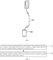
- FIG. 1 is a schematic diagram illustrating a communication system according to an embodiment of the disclosure.
- the communication system may include, but is not limited to, a network-side device and a terminal.
- the number and shape of devices illustrated in FIG. 1 are exemplary and do not constitute a limitation of embodiments of the disclosure.
- the communication system may include two or more network-side devices and two or more terminals.
- the communication system illustrated in FIG. 1 includes a network-side device 101 and a terminal 102.
- LTE long term evolution
- 5G 5th generation
- NR 5G new radio
- the network-side device 101 in embodiments of the disclosure is an entity in the network side for transmitting or receiving signals.
- the network-side device 101 may be an evolved NodeB (eNB), a transmission reception point (TRP), or a next generation NodeB (gNB) in an NR system, a base station in other mobile communication systems in the future, or an access node in a wireless fidelity (WiFi) system.
- eNB evolved NodeB
- TRP transmission reception point
- gNB next generation NodeB
- WiFi wireless fidelity
- a detailed technology and a detailed device form employed by the network-side device are not limited in embodiments of the disclosure.
- the network-side device in embodiments of the disclosure may be combined by a central unit (CU) and a distributed unit (DU), in which CU may also be called a control unit.
- CU central unit
- DU distributed unit
- the terminal 102 in embodiments of the disclosure is an entity in a user side for receiving or transmitting signals, such as a mobile phone.
- the terminal may also be called a terminal, a user equipment (UE), a mobile station (MS), a mobile terminal (MT), etc.
- the communication system in embodiments of the disclosure is intended to clearly describe the technical solution of embodiments of the disclosure, and does not constitute a limitation of the technical solution in embodiments of the disclosure.
- Those skilled in the art may know that, with the evolution of the system architecture and the emergence of a new service scene, the technical solution in embodiments of the disclosure is equally applicable to similar technical problems.
- FIG. 2 is a flowchart illustrating a method for feeding back CSI according to an embodiment of the disclosure.
- the method for feeding back the CSI in embodiments of the disclosure may be performed by a terminal, that is, the method for feeding back the CSI in embodiments of the disclosure is described from a terminal side.
- the method may include, but is not limited to, the following.
- codebook indication information corresponding to a data transmission layer is determined based on a length of a TD basis vector or a length of a DD basis vector, and a codebook parameter configured by a network-side device.
- the length of the TD basis vector or the length of the DD basis vector may be determined.
- the length may be determined by the terminal based on relevant information, or the length may also be configured by the network-side device.
- the terminal may implicitly determine the length of the TD basis vector or the length of the DD basis vector based on a relevant parameter configured by the network-side device.
- the terminal may determine the length of the TD basis vector or the length of the DD basis vector based on information, such as estimated Doppler offset information and an estimated Doppler extension.
- the terminal may also receive the length of the TD basis vector or the length of the DD basis vector configured by the network-side device.
- the terminal may receive a codebook parameter sent by the network-side device (such as a base station).
- the codebook parameter is configured by the network-side device, and used to indicate a maximum support parameter for a terminal to feed back the CSI information.
- the terminal may receive the codebook parameter configured by the network-side device (such as the base station), and determine the codebook indication information corresponding to the data transmission layer based on the codebook parameter and the length of the TD basis vector.
- the codebook indication information may at least include, but not limited to, one or more combinations of a matrix combined by at least one SD basis vector, a combination coefficient matrix, a matrix combined by at least one FD basis vector, or a matrix combined by at least one TD basis vector.
- the length of the TD basis vector is configured to determine the TD basis vector employed in a codebook, and the TD basis vector is introduced on the basis of the Rel-16 or 17 Type II codebook.
- the term "at least one" may be understood as one or more, and the term “more” means at least two, such as two, three, etc., unless otherwise specified.
- the terminal may receive the codebook parameter configured by the network-side device (such as the base station) and determine the codebook indication information corresponding to the data transmission layer based on the codebook parameter and the length of the DD basis vector.
- the codebook indication information may at least include, but not limited to, one or more combinations of the matrix combined by the at least one SD basis vector, the combination coefficient matrix, the matrix combined by the at least one FD basis vector, or a matrix combined by at least one DD basis vector.
- the length of the DD basis vector is used to determine the DD basis vector employed in the codebook, and the DD basis vector is introduced on the basis of the Rel-16 or 17 Type II codebook.
- CSI including the codebook indication information is sent to the network-side device, in which the codebook indication information indicates the network-side device to determine precoding matrixes corresponding to different time instances.
- the terminal may send the CSI including the codebook indication information to the network-side device.
- the network-side device may determine the precoding matrixes corresponding to different time instances based on the codebook indication information in the CSI when receiving the CSI sent by the terminal.
- the codebook indication information may include a matrix combined by multiple SD basis vectors, the combination coefficient matrix, a matrix combined by multiple FD basis vectors, and a matrix combined by multiple TD basis vectors.
- the network-side device may, based on the codebook indication information, calculate the precoding matrixes corresponding to different time instances by employing a codebook structure W f * ⁇ W 1 W 2 W t H , or predict the precoding matrixes corresponding to different time instances by employing a precoding matrix indicator (PMI) prediction algorithm, where W 1 represents the matrix combined by the multiple SD basis vectors or a unit matrix combined by at least one unit vector, W 2 represents the combination coefficient matrix, W f represents the matrix combined by the multiple FD basis vectors, and W t represents the matrix combined by the multiple TD basis vectors.
- PMI precoding matrix indicator
- the codebook indication information may include the matrix combined by the multiple SD basis vectors, the combination coefficient matrix, the matrix combined by the multiple FD basis vectors, and a matrix combined by multiple DD basis vectors.
- the network-side device may, based on the codebook indication information, calculate the precoding matrixes corresponding to different time instances by employing a codebook structure W 1 W ⁇ 2 ( W f ⁇ W d ) H , or predict the precoding matrixes corresponding to different time instances by employing the PMI prediction algorithm, where W 1 represents the matrix combined by the multiple SD basis vectors or the unit matrix combined by the at least one unit vector, W 2 represents the combination coefficient matrix, W f represents the matrix combined by the multiple FD basis vectors, and W d represents the matrix combined by the multiple DD basis vectors.
- the length of the TD basis vector or the length of the DD basis vector may be determined, such that the TD basis vector or the DD basis vector employed in the codebook is determined based on the length.
- a precoding calculation or prediction at a future time instance may be realized, such that a calculated preset code or a predicted preset code matches a channel corresponding to a future time instance.
- the preset codes corresponding to different time instances be determined but also a redundant configuration of the codebook parameter or a redundant report of the codebook parameters may be avoided, thus reducing a signaling configuration overhead or a report feedback overhead.
- the terminal may implicitly determine the length of the TD basis vector or the length of the DD basis vector based on the relevant parameter configured by the network-side device.
- the method for feeding back CSI may include, but is not limited to, the following.
- the length of the TD basis vector or the length of the DD basis vector is determined based on a first parameter configured by a network-side device.
- the terminal may implicitly determine the length of the TD basis vector or the length of the DD basis vector based on the first parameter configured by the network-side device.
- the first parameter may include, but is not limited to, at least one of: a number of CSI-RS resources, a number of CSI-RS resources within a CSI-RS measurement window, a size of a CSI-RS measurement window, an interval between time instances of adjacent CSI measurements, a number of CSI measurements, a number of CSI measurements within a CSI-RS measurement window, or a parameter W.
- the CSI-RS measurement window configured by the network-side device is to facilitate performing one or more channel measurements for the CSI-RS resources within a certain time range, and there may be a possibility that the CSI-RS measurement window is not configured by the network-side device.
- the first parameter is the number of CSI-RS resources or the number of CSI-RS resources within the CSI-RS measurement window
- the length of the TD basis vector or the length of the DD basis vector may be determined based on the number of CSI-RS resources or the number of CSI-RS resources within the CSI-RS measurement window.
- the length of the TD basis vector or the length of the DD basis vector is equal to the number of CSI-RS resources or the number of CSI-RS resources within the CSI-RS measurement window configured by the network-side device.
- the number N CSI-RS of CSI-RS resources configured by the network-side device is 4.
- the length N 4 of the TD basis vector or the length N 4 of the DD basis vector is 4.
- the number N CSI-RS of the CSI-RS resources within the CSI-RS measurement window configured by the network-side device is 6.
- the length N 4 of the TD basis vector or the length N 4 of the DD basis vector is 6.
- the length of the TD basis vector or the length of the DD basis vector is equal to Q 1 times of the number of CSI-RS resources configured by the network-side device, where Q 1 is a positive integer.
- Q 1 is 1 and the number N CSI-RS of CSI-RS resources configured by the network-side device is 4.
- the length N 4 of the TD basis vector or the length N 4 of the DD basis vector is 4.
- the length of the TD basis vector or the length of the DD basis vector is equal to Q 1 times of the number of CSI-RS resources within the CSI-RS measurement window configured by the network-side device, where Q 1 is a positive integer. For example, Q 1 is 1 and the number N CSI-RS of CSI-RS resources within the CSI-RS measurement window configured by the network-side device is 6, and then it may be determined that the length N 4 of the TD basis vector or the length N 4 of the DD basis vector is 6.
- the length of the TD basis vector or the length of the DD basis vector is equal to N CSI ⁇ RS C u Q 1 , where Q 1 is a positive integer, N CSI-RS represents the number of CSI-RS resources or the number of CSI-RS resources within the CSI-RS measurement window configured by the network-side device, and C u represents a compression unit in a TD.
- Q 1 is 1, the number N CSI-RS of CSI-RS resources configured by the network-side device is 4, and the C u is 2ms.
- the N CSI-RS CSI-RS resources when the number N CSI-RS of CSI-RS resources is greater than 1, the N CSI-RS CSI-RS resources may be in the same time domain type or different time domain types.
- the time domain type may be periodic, semi-persistent, and non-periodic types.
- the N CSI-RS CSI-RS resources when the number N CSI-RS of CSI-RS resources is greater than 1, the N CSI-RS CSI-RS resources may also be CSI-RS resources with different functions.
- a CSI-RS resource is configured as a CSI-RS resource for channel acquisition, and the remaining CSI-RS resources are configured as CSI-RS resources for time-frequency tracking.
- the first parameter is the size of the CSI-RS measurement window and the interval between the time instances of the adjacent CSI measurements. Then the length of the TD basis vector or the length of the DD basis vector may be determined based on the size of the CSI-RS measurement window and the interval between the time instances of the adjacent CSI measurements configured by the network-side device.
- the length of the TD basis vector or the length of the DD basis vector is equal to W meas ⁇ 1 d + 1 , where W meas represents the size of the CSI-RS measurement window, and d represents the interval between the time instances of the adjacent CSI measurements, or d represents a maximum interval or a minimum interval between adjacent CSI measurements, or d represents an average of intervals of multiple adjacent CSI measurements.
- the first parameter is the number of CSI measurements or the number of CSI measurements within the CSI-RS measurement window. Then the length of the TD basis vector or the length of the DD basis vector may be determined based on the number of CSI measurements or the number of CSI measurements within the CSI-RS measurement window configured by the network-side device.
- the length of the TD basis vector or the length of the DD basis vector is equal to Q 2 times of the number of CSI measurements configured by the network-side device, where Q 2 is a positive integer.
- the length of the TD basis vector or the length of the DD basis vector is equal to Q 2 times of the number of CSI measurements within the CSI-RS measurement window configured by the network-side device, where Q 2 is a positive integer.
- the length of the TD basis vector or the length of the DD basis vector is equal to B C u Q 2 , where Q 2 is a positive integer, B represents the number of CSI measurements or the number of CSI measurements within the CSI-RS measurement window configured by the network-side device, and C u represents a compression unit in the TD.
- the Q 2 is 1, the number B of CSI measurements or the number B of CSI measurements within the CSI-RS measurement window configured by the network-side device is 4, and the C u is 2ms.
- the first parameter is the parameter W. Then the length of the TD basis vector or the length of the DD basis vector may be determined based on the parameter W configured by the network-side device.
- W mod C u 0
- C u represents the compression unit in the TD
- mod represents a modulo function.
- the length N 4 of the TD basis vector or the length N 4 of the DD basis vector is 2.
- the length of the TD basis vector or the length of the DD basis vector is equal to W C u or W C u , where W mod C u ⁇ 0, ⁇ represents ceiling, and ⁇ represents flooring.
- W mod C u ⁇ 0, ⁇ represents ceiling, and ⁇ represents flooring.
- the parameter W is determined by at least one of following parameters 1) to 4):
- the parameter W represents a time length between a time slot corresponding to a time instance when a first CSI-RS resource is received for a CSI measurement and a time slot corresponding to a time instance when the right boundary of the CSI reporting window is located, and a unit of the length of the time is one time slot.
- values of N CSI-RS , B, d, Q 1 , Q 2 , W meas , and W meas mentioned above may be reported by the terminal, configured by the network-side device, or pre-defined by the terminal and the network-side device.
- the terminal also needs to determine the compression unit C u of the TD.
- the compression unit C u may be determined in any of the following ways.
- the compression unit C u may be ⁇ T c , where ⁇ is an integer less than or equal to 1, and T c represents a channel coherence time.
- the coherence time T c 1 f d , where f d represents a Doppler extension of the channel.
- the compression unit C u may be a measurement period of the CSI-RS resource.
- the compression unit C u may be ⁇ d 1 , where ⁇ is an integer greater than or equal to 1, and d 1 represents the interval between the adjacent CSI measurements.
- d 1 may represent the interval between the adjacent CSI measurements, and values of d 1 and ⁇ may be employed to determine the compression unit C u .
- the compression unit C u may be ⁇ d 2 , where ⁇ is an integer greater than or equal to 1, and d 2 represents a maximum interval or a minimum interval between adjacent CSI measurements, or d 2 may also represent an average of intervals of multiple adjacent CSI measurements.
- d 2 may represent a maximum interval or a minimum interval between the adjacent CSI measurements, and values of d 2 and ⁇ may be employed to determine the compression unit C u .
- the values of ⁇ and ⁇ above may be reported by the terminal, or configured by the network-side device, or predefined by the terminal and the network-side device.
- codebook indication information corresponding to a data transmission layer is determined based on a codebook parameter and a length configured by a network-side device. Actions at block 302 may be respectively realized by employing any one of embodiments of the disclosure, which is not limited in embodiments of the disclosure and is not described in detail.
- CSI including the codebook indication information is sent to the network-side device, in which the codebook indication information indicates the network-side device to determine precoding matrixes corresponding to different time instances.
- Action at block 302 may be respectively realized by employing any one of embodiments of the disclosure, which is not limited in embodiments of the disclosure and is not described in detail.
- the length of the TD basis vector or the length of the DD basis vector may be implicitly determined based on the relevant parameter configured by the network-side device, so as to determine the TD basis vector or the DD basis vector used in the codebook based on the length.
- a precoding calculation or prediction at a future time instance may be realized, such that a calculated preset code or a predicted preset code matches a channel at a future time instance.
- preset codes corresponding to different time instances be determined, but also a redundant configuration of a codebook parameter or a redundant reporting of a codebook parameter may be avoided, thus reducing a signaling configuration overhead or a reporting feedback overhead.
- the terminal may determine the length of the TD basis vector or the length of the DD basis vector based on estimated Doppler offset information and an estimated Doppler extension. For example, the terminal receives CSI-RS resources configured by the network-side device and performs CSI measurement processing by employing the CSI-RS resources to obtain the estimated Doppler offset information and the estimated Doppler extension. The terminal may determine the length of the TD basis vector or the length of the DD basis vector based on the estimated Doppler offset information and the estimated Doppler extension, thus determining the TD basis vector or the DD basis vector employed in the codebook by employing the length.
- a precoding calculation or prediction at a future time instance may be realized, such that a calculated preset code or a predicted preset code matches a channel at a future time instance.
- preset codes corresponding to different time instances may be determined, but may also a redundant configuration of the codebook parameter or a redundant reporting of the codebook parameter may be avoided, thus reducing a signaling configuration overhead or a reporting feedback overhead.
- the terminal may receive the length of the TD basis vector or the length of the DD basis vector configured by the network-side device. That is, the length of the TD basis vector or the length of the DD basis vector may be configured for the terminal by the network-side device.
- the network-side device may implicitly determine the length of the TD basis vector or the length of the DD basis vector based on the relevant parameter (such as the first parameter mentioned above) configured by the network-side device, or the network-side device may determine the length of the TD basis vector or the length of the DD basis vector based on the Doppler offset information and the Doppler extension reported by the terminal.
- the network-side device may send the length of the TD basis vector or the length of the DD basis vector to the terminal when determining the length of the TD basis vector or the length of the DD basis vector of the terminal, such that the terminal may determine the TD basis vector or the DD basis vector employed in the codebook by employing the length.
- a precoding calculation or prediction at a future time instance may be realized, such that a calculated preset code or a predicted preset code matches a channel at a future time instance.
- preset codes corresponding to different time instances are determined, but may also a redundant configuration of the codebook parameter or a redundant reporting of the codebook parameters may be avoided, thus reducing a signaling configuration overhead or a reporting feedback overhead.
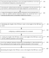
- FIG. 4 is a flow chart illustrating a method for feeding back CSI according to a yet another embodiment of the disclosure. It should be noted that, the method for feeding back the CSI of embodiments of the disclosure may be performed by the network-side device. As illustrated in FIG. 4 , the method for feeding back the CSI may include but is not limited to the following.
- a length of a TD basis vector or a length of a DD basis vector is determined.
- the network-side device may implicitly determine the length of the TD basis vector or the length of the DD basis vector based on a relevant parameter configured by the network-side device.
- the network-side device may determine the length of the TD basis vector or the length of the DD basis vector based on information such as Doppler offset information and a Doppler extension reported by the terminal.
- the terminal receives CSI-RS resources configured by the network-side device and performs CSI measurement processing by employing the CSI-RS resources to estimate the Doppler offset information and the Doppler extension.
- the terminal may report estimated Doppler offset information and a estimated Doppler extension to the network-side device, such that the network-side device may determine the length of the TD basis vector or the length of the DD basis vector based on the estimated Doppler offset information and the estimated Doppler extension.
- a codebook parameter is configured for a terminal.
- the length of the TD basis vector or the length of the DD basis vector and the codebook parameter are sent to the terminal.
- the network-side device sends the length of the TD basis vector or the length of the DD basis vector and the codebook parameter to the terminal, such that the terminal determines codebook indication information corresponding to a data transmission layer based on the length of the TD basis vector or the length of the DD basis vector and the codebook parameter.
- the terminal may receive the codebook parameter and the length of the TD basis vector configured by the network-side device (such as a base station), and determine the codebook indication information corresponding to the data transmission layer based on the codebook parameter and the length of the TD basis vector.
- the codebook indication information may at least include one or more combinations of: a matrix combined by at least one SD basis vector, a combination coefficient matrix, a matrix combined by at least one FD basis vector, or a matrix combined by at least one TD basis vector.
- the length of the TD basis vector is used to determine the TD basis vector employed in a codebook, and the TD basis vector is introduced on the basis of a Rel-16 or 17 Type II codebook.
- the terminal may receive the codebook parameter and the length of the DD basis vector configured by the network-side device (such as the base station), and determine the codebook indication information corresponding to the data transmission layer based on the codebook parameter and the length of the DD basis vector.
- the codebook indication information may at least include, but not be limited to, one or more combinations of the matrix combined by the at least one SD basis vector, the combination coefficient matrix, the matrix combined by the at least one FD basis vector, or a matrix combined by at least one DD basis vector.
- the length of the DD basis vector is used to determine the DD basis vector employed in the codebook, and the DD basis vector is introduced on the basis of the Rel-16 or 17 Type II codebook.
- codebook indication information corresponding to a data transmission layer determined by the terminal based on the length and the codebook parameter is received.
- the terminal sends the codebook indication information to the network-side device, such that the network-side device may receive the codebook indication information sent by the terminal.
- precoding matrixes corresponding to different time instances are determined based on the codebook indication information.
- a codebook structure formula may be employed to calculate the precoding matrixes corresponding to different time instances based on the codebook indication information, or a PMI prediction algorithm may be employed to predict the precoding matrixes corresponding to different time instances.
- the codebook indication information may include a matrix combined by multiple SD basis vectors, the combination coefficient matrix, a matrix combined by multiple FD basis vectors, and a matrix combined by multiple TD basis vectors.
- the network-side device may, based on the codebook indication information, calculate the precoding matrixes corresponding to different time instances by employing a codebook structure W f ⁇ ⁇ W 1 W 2 W t H , or predict the precoding matrixes corresponding to different time instances by employing the PMI prediction algorithm, where W 1 represents the matrix combined by the multiple SD basis vectors or a unit matrix combined by at least one unit vector, W 2 represents the combination coefficient matrix, W f represents the matrix combined by the multiple FD basis vectors, and W, represents the matrix combined by multiple TD basis vectors.
- the codebook indication information may include the matrix combined by the multiple SD basis vectors, the combination coefficient matrix, the matrix combined by the multiple FD basis vectors, and a matrix combined by multiple DD basis vectors.
- the network-side device may, based on the codebook indication information, calculate the precoding matrixes corresponding to different time instances by employing a codebook structure W 1 W ⁇ 2 ( W f ⁇ W d ) H , or predict the precoding matrixes corresponding to different time instances by employing the PMI prediction algorithm, where W 1 represents the matrix combined by the multiple SD basis vectors or the unit matrix combined by the at least one unit vector, W 2 represents the combination coefficient matrix, W f represents the matrix combined by the multiple FD basis vectors, and W d represents the matrix combined by the multiple DD basis vectors.
- the length of the TD basis vector or the length of the DD basis vector may be determined, such that the TD basis vector or the DD basis vector employed in the codebook may be determined based on the length.
- a precoding calculation or prediction at a future time instance may be realized, such that a calculated preset code or a predicted preset code matches a channel at a future time instance.
- preset codes corresponding to different time instances may be determined, but also a redundant configuration of a codebook parameter or a redundant reporting of a codebook parameter may be avoided, thus reducing a signaling configuration overhead or a reporting feedback overhead.
- the network-side device may implicitly determine the length of the TD basis vector or the length of the DD basis vector based on the relevant parameter configured by the network-side device.
- the method for feeding back the CSI may include, but is not limited to, the following.
- a length of the TD basis vector or a length of the DD basis vector is determined based on a first parameter configured by the network-side device.
- a terminal may implicitly determine the length of the TD basis vector or the length of the DD basis vector based on the first parameter configured by the network-side device.
- the first parameter may include, but is not limited to, at least one of a number of CSI-RS resources, a number of CSI-RS resources within a CSI-RS measurement window, a size of a CSI-RS measurement window, an interval between time instances of adjacent CSI measurements, a number of CSI measurements, a number of CSI measurements within a CSI-RS measurement window, or a parameter W.
- the CSI-RS measurement window configured by the network-side device is to facilitate description that one or more channel measurements is performed for the CSI-RS resources within a certain time, and there may be a possibility that the CSI-RS measurement window is not configured by the network-side device.
- the first parameter is the number of CSI-RS resources or the number of CSI-RS resources within the CSI-RS measurement window
- the length of the TD basis vector or the length of the DD basis vector may be determined based on the number of CSI-RS resources or the number of CSI-RS resources within the CSI-RS measurement window.
- the length of the TD basis vector or the length of the DD basis vector is equal to the number of CSI-RS resources or the number of CSI-RS resources within the CSI-RS measurement window configured by the network-side device.
- the number N CSI-RS of CSI-RS resources configured by the network-side device is 4.
- the length N 4 of the TD basis vector or the length N 4 of the DD basis vector is 4.
- the number N CSI-RS of the CSI-RS resources within the CSI-RS measurement window configured by the network-side device is 6.
- the length N 4 of the TD basis vector or the length N 4 of the DD basis vector is 6.
- the length of the TD basis vector or the length of the DD basis vector is equal to Q 1 times of the number of CSI-RS resources configured by the network-side device, where Q 1 is a positive integer. For example, Q 1 is 1, and the number N CSI-RS of CSI-RS resources configured by the network-side device is 4. Then it may be determined that the length N 4 of the TD basis vector or the length N 4 of the DD basis vector is 4.
- the length of the TD basis vector or the length of the DD basis vector is equal to Q 1 times of the number of CSI-RS resources within the CSI-RS measurement window configured by the network-side device, where Q 1 is a positive integer.
- Q 1 is 1, and the number N CSI-RS of CSI-RS resources within the CSI-RS measurement window configured by the network-side device is 6.
- the length N 4 of the TD basis vector or the length N 4 of the DD basis vector is 6.
- the length of the TD basis vector or the length of the DD basis vector is equal to N CSI ⁇ RS C u Q 1 , where Q 1 is a positive integer, N CSI-RS represents the number of CSI-RS resources or the number of CSI-RS resources within the CSI-RS measurement window configured by the network-side device, and C u represents a compression unit in a TD.
- Q 1 is 1, the number N CSI-RS of CSI-RS resources configured by the network-side device is 4, and the C u is 2ms.
- the N CSI-RS CSI-RS resources when the number N CSI-RS of CSI-RS resources is greater than 1, the N CSI-RS CSI-RS resources may be in the same time domain type or different time domain types.
- the time domain type may be periodic, semi-persistent, and non-periodic types.
- the N CSI-RS CSI-RS resources when the number N CSI-RS of CSI-RS resources is greater than 1, the N CSI-RS CSI-RS resources may also be CSI-RS resources with different functions.
- a CSI-RS resource is configured as a CSI-RS resource for channel acquisition, and the remaining CSI-RS resources are configured as CSI-RS resources for time-frequency tracking.
- the first parameter is the size of the CSI-RS measurement window and the interval between the time instances of the adjacent CSI measurements. Then the length of the TD basis vector or the length of the DD basis vector may be determined based on the size of the CSI-RS measurement window and the interval between the time instances of the adjacent CSI measurements configured by the network-side device.
- the length of the TD basis vector or the length of the DD basis vector is equal to W meas ⁇ 1 d + 1 , where W meas represents the size of the CSI-RS measurement window, and d represents the interval between the time instances of the adjacent CSI measurements, d represents a maximum interval or a minimum interval between adjacent CSI measurements, or d represents an average of intervals of multiple adjacent CSI measurements.
- the first parameter is the number of CSI measurements or the number of CSI measurements within the CSI-RS measurement window. Then the length of the TD basis vector or the length of the DD basis vector may be determined based on the number of CSI measurements or the number of CSI measurements within the CSI-RS measurement window configured by the network-side device.
- the length of the TD basis vector or the length of the DD basis vector is equal to the number of CSI measurements or the number of CSI measurements within the CSI-RS measurement window configured by the network-side device.
- the number B of CSI measurements configured by the network-side device is 2.
- the length N 4 of the TD basis vector or the length N 4 of the DD basis vector is 2.
- the number B of CSI measurements within the CSI-RS measurement window configured by the network-side device is 2.
- the length N 4 of the TD basis vector or the length N 4 of the DD basis vector is 2.
- the length of the TD basis vector or the length of the DD basis vector is equal to Q 2 times of the number of CSI measurements configured by the network-side device, where Q 2 is a positive integer.
- the length of the TD basis vector or the length of the DD basis vector is equal to Q 2 times of the number of CSI measurements within the CSI-RS measurement window configured by the network-side device, where Q 2 is a positive integer.
- the length of the TD basis vector or the length of the DD basis vector is equal to B C u Q 2 , where Q 2 is a positive integer, B represents the number of CSI measurements or the number of CSI measurements within the CSI-RS measurement window configured by the network-side device, and C u represents a compression unit in the TD.
- the Q 2 is 1, the number B of CSI measurements or the number B of CSI measurements within the CSI-RS measurement window configured by the network-side device is 4, and the C u is 2ms.
- the first parameter is the parameter W. Then the length of the TD basis vector or the length of the DD basis vector may be determined based on the parameter W configured by the network-side device.
- W mod C u 0
- C u represents the compression unit in the TD
- mod represents a modulo function.
- the length N 4 of the TD basis vector or the length N 4 of the DD basis vector is 2.
- W mod C u 0, ⁇ represents ceiling, and ⁇ represents flooring.
- the parameter W is determined by at least one of following parameters 1) to 4):
- the parameter W represents a time length between a time slot corresponding to a time instance when a first CSI-RS resource is received for a CSI measurement and a time slot corresponding to a time instance when the right boundary of the CSI reporting window is located, and a unit of the length of the time is one time slot.
- the parameter W represents a time length between the time slot corresponding to the right boundary or the left boundary of the CSI-RS measurement window and a time slot corresponding to a time instance when the right boundary of the CSI reporting window is located.
- the parameter W represents a time length between the time slot corresponding to the CSI reference resource and a time slot corresponding to a time instance when the right boundary of the CSI reporting window is located
- values of N CSI-RS , B, d, Q 1 , Q 2 , W meas , and W meas mentioned above may be reported by the terminal, configured by the network-side device, or pre-defined by the terminal and the network-side device.
- the network-side device also needs to determine the compression unit C u of the TD.
- the compression unit C u may be determined in any of the following ways.
- the compression unit C u may be ⁇ T c , where ⁇ is an integer less than or equal to 1, and T c represents a channel coherence time.
- the coherence time T c 1 f d , where f d represents a Doppler extension of the channel.
- the compression unit C u may be a measurement period of the CSI-RS resource.
- the compression unit C u may be ⁇ d 1 , where ⁇ is an integer greater than or equal to 1, and d 1 represents the interval between the adjacent CSI measurements.
- d 1 may represent the interval between the adjacent CSI measurements, and values of d 1 and ⁇ may be employed to determine the compression unit C u .
- the compression unit C u may be ⁇ d 2 , where ⁇ is an integer greater than or equal to 1, and d 2 represents a maximum interval or a minimum interval between adjacent CSI measurements, or d 2 may also represent an average of intervals of multiple adjacent CSI measurements.
- d 2 may represent a maximum interval or a minimum interval between the adjacent CSI measurements, and values of d 2 and ⁇ may be employed to determine the compression unit C u .
- the terminal moves at a velocity of 27 Km/h, and a system carrier frequency of a cell where the UE is located is 4 GHz.
- the meaning of the W may be represented by any one of the above meanings.
- the values of ⁇ and ⁇ above may be reported by the terminal, configured by the network-side device, or predefined by the terminal and the network-side device.
- f d mentioned above may be reported to the network-side device by the terminal.
- a codebook parameter is configured for a terminal. Actions at block 502 may be respectively realized by employing any one of embodiments of the disclosure, which is not limited in embodiments of the disclosure and is not described in detail.
- the length of the TD basis vector or the length of the DD basis vector and the codebook parameter are sent to the terminal.
- Actions at block 503 may be respectively realized by employing any one of embodiments of the disclosure, which is not limited in embodiments of the disclosure and is not described in detail.
- codebook indication information corresponding to a data transmission layer determined by the terminal based on the length and the codebook parameter is received.
- Actions at block 504 may be respectively realized by employing any one of embodiments of the disclosure, which is not limited in embodiments of the disclosure and is not described in detail.
- precoding matrixes corresponding to different time instances are determined based on the codebook indication information.
- the precoding matrixes corresponding to different time instances are determined by employing a codebook structure or a PMI prediction algorithm based on the codebook indication information and a way of determining the length of the TD basis vector or the length of the DD basis vector.
- the precoding matrixes are obtained in different ways, such as employing the prediction algorithm to predict the precoding matrixes, or directly employing the codebook structure to calculate the precoding matrixes.
- the network-side device (such as a base station) configures a non-periodic CSI-RS resource set to the terminal (UE), and the non-periodic CSI-RS resource set includes four non-periodic CSI-RS resources.
- Downlink channel information at four different time instances within one CSI-RS measurement window is measured based on the four non-periodic CSI-RS resources, and an interval of adjacent CSI-RS resources is d.
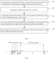
- FIG. 6 illustrates a relationship between a CSI-RS measurement and a CSI reporting in a TD, where a measurement time instance of the first CSI-RS resource is t 0 , and a measurement time instance of a last CSI-RS resource is t 0 +3.
- the UE Based on the downlink channels measured at the CSI-RS resources at the four different time instances and based on the codebook parameter configured by the base station, the UE calculates W 1 combined by the multiple SD basis vectors, the combination coefficient W 2 , W f combined by the multiple FD basis vectors, and W t or W d combined by the multiple TD basis vectors or DD basis vectors in the codebook.
- the UE reports these parameters to the base station at time t 0 +n, and the base station calculates the precoding matrixes corresponding to time instances with the length N 4 by employing W f * ⁇ W 1 W 2 W t H or W 1 W ⁇ 2 ( W f ⁇ W d ) H .
- the base station may employ the PMI prediction algorithm to calculate precoding matrixes corresponding to different time instances with a time range from t 0 +3 to t 0 + l .
- the length N 4 of the TD basis vector or the length N 4 of the DD basis vector is defined as W CSI C u , where W CSI represents a length of the CSI reporting window and C u represents the compression unit in the TD.
- the length N 4 is configured for the UE by the base station via a radio resource control (RRC) signaling, and the UE reports S (S>1) selected basis vectors with a length N 4 to the base station. Then the base station may employ the above codebook algorithm to directly calculate the precoding matrixes corresponding to different time instances within the CSI reporting window.
- RRC radio resource control
- the precoding matrixes corresponding to N 4 time instances may be obtained by W f ⁇ ⁇ W 1 W 2 W t H or W 1 W ⁇ 2 (W f ⁇ W d ) H , where W 1 and W f follow a conventional calculation way of the Rel-16 or 17 Type II, and W d or W t selects the V basis vectors from the codebook combined by the basis vectors with the length N 4 .
- the length of the TD basis vector or the length of the DD basis vector may be determined, and then the TD basis vector or the DD basis vector employed in the codebook is determined by employing the length.
- a precoding calculation or prediction at a future time instance may be realized, such that a calculated preset code or a predicted preset code matches a channel at a future time instance.
- preset codes corresponding to different time instances may be determined, but also a redundant configuration of the codebook parameter or a redundant reporting of the codebook parameter may be avoided, thus reducing a signaling configuration overhead or a reporting feedback overhead.
- the method is introduced from the perspective of terminal and network-side device.
- the terminal and the network-side device may include a hardware structure and a software module in order to realize the above functions in the form of a hardware structure, a software module, or a hardware structure plus a software module.
- One of these functions may be performed by a hardware structure, a software module, or a hardware structure plus a software module.
- FIG. 7 is a block diagram illustrating a communication device 70 according to an embodiment of the disclosure.
- the communication device 70 illustrated in FIG. 7 may include a receiving and sending module 701 and a processing module 702.
- the receiving and sending module 701 may include a sending module and/or a receiving module.
- the sending module is configured to achieve a sending function
- the receiving module is configured to achieve a receiving function
- the receiving and sending module 701 may achieve the sending function and/or the receiving function.
- the communication device 70 may be a terminal, a device in a terminal, or a device used in combination with a terminal. Or, the communication device 70 may be a network-side device, a device within a network-side device, or a device used in combination with a network-side device.
- the communication device 70 is the terminal.
- the processing module 702 is configured to determine codebook indication information corresponding to a data transmission layer based on a length of a TD basis vector or a length of a DD basis vector, and a codebook parameter configured by a network-side device; and the receiving and sending module 701 is configured to send CSI including the codebook indication information to the network-side device, in which the codebook indication information indicates the network-side device to determine precoding matrixes corresponding to different time instances.
- the processing module 702 is specifically configured to: determine the length of the TD basis vector or the length of the DD basis vector; and determine the codebook indication information corresponding to the data transmission layer based on the length and the codebook parameter configured by the network-side device.
- the processing module 702 is specifically configured to determine the length of the TD basis vector or the length of the DD basis vector based on a first parameter configured by the network-side device.
- the first parameter is a number of CSI-RS resources or a number of CSI-RS resources within a CSI-RS measurement window.
- the processing module 702 is specifically configured to determine that the length of the TD basis vector or the length of the DD basis vector is equal to the number of CSI-RS resources or the number of CSI-RS resources within the CSI-RS measurement window configured by the network-side device; determine that the length of the TD basis vector or the length of the DD basis vector is equal to Q 1 times of the number of CSI-RS resources configured by the network-side device; determine that the length of the TD basis vector or the length of the DD basis vector is equal to Q 1 times of the number of CSI-RS resources within the CSI-RS measurement window configured by the network-side device; or determine that the length of the TD basis vector or the length of the DD basis vector is equal to N CSI ⁇ RS C u Q 1 , where Q 1 is a positive integer, N CSI-RS represents the number of CSI-RS resources
- the first parameter is a size of a CSI-RS measurement window and an interval between time instances of adjacent CSI measurements.
- the processing module 702 is specifically configured to determine that the length of the TD basis vector or the length of the DD basis vector is equal to W meas ⁇ 1 d + 1 , where W meas represents the size of the CSI-RS measurement window, and d represents the interval between the time instances of the adjacent CSI measurements, a maximum interval or a minimum interval between adjacent CSI measurements, or an average of intervals of multiple adjacent CSI measurements.
- the first parameter is a number of CSI measurements or a number of CSI measurements within a CSI-RS measurement window.
- the processing module 702 is specifically configured to determine that the length of the TD basis vector or the length of the DD basis vector is equal to the number of CSI-RS measurements or the number of CSI-RS measurements within the CSI-RS measurement window configured by the network-side device; determine that the length of the TD basis vector or the length of the DD basis vector is equal to Q 2 times of the number of CSI measurements configured by the network-side device; determine that the length of the TD basis vector or the length of the DD basis vector is equal to Q 2 times of the number of CSI measurements within the CSI-RS measurement window configured by the network-side device; or determine that the length of the TD basis vector or the length of the DD basis vector is equal to B C u Q 2 , where Q 2 is a positive integer, B represents the number of CSI measurements or the number of CSI measurements within the CSI-RS measurement window configured by the network-
- the first parameter is a parameter W.
- the processing module 702 is further configured to determine the compression unit C u in the TD.
- the compression unit C u is ⁇ T c , where ⁇ is an integer less than or equal to 1, and T c represents a channel coherence time; the compression unit C u is a measurement period of the CSI-RS resource; the compression unit C u is ⁇ d 1 , where ⁇ is an integer greater than or equal to 1, and d 1 represents the interval between the adjacent CSI measurements; or the compression unit C u is ⁇ d 2 , where ⁇ is an integer greater than or equal to 1, and d 2 represents the maximum interval or the minimum interval between the adjacent CSI measurements, or the average of the intervals of the multiple adjacent CSI measurements.
- the processing module 702 is specifically configured to determine the length of the TD basis vector or the length of the DD basis vector based on Doppler offset information and a Doppler extension estimated based on a CSI-RS by the terminal.
- the processing module 701 is further configured to receive the length of the TD basis vector or the length of the DD basis vector configured by the network-side device.
- the codebook indication information at least includes one or more combinations of: a matrix combined by at least one SD basis vector, a combination coefficient matrix, a matrix combined by at least one FD basis vector, or a matrix combined by at least one TD basis vector or at least one DD basis vector.
- the communication device 70 is the network-side device.
- the processing module 702 is configured to determine a length of a TD basis vector or a length of a DD basis vector; the processing module 702 is further configured to configure a codebook parameter for a terminal; the receiving and sending module 701 is configured to send the length of the TD basis vector or the length of the DD basis vector and the codebook parameter to the terminal; the receiving and sending module 701 is further configured to receive codebook indication information corresponding to a data transmission layer determined by the length and the codebook parameter of the terminal; and the processing module 702 is further configured to determine precoding matrixes corresponding to different time instances based on the codebook indication information.
- the processing module 702 is specifically configured to determine the length of the TD basis vector or the length of the DD basis vector based on a first parameter configured by the network-side device.
- the first parameter is a number of CSI-RS resources or a number of CSI-RS resources within a CSI-RS measurement window.
- the processing module 702 is specifically configured to determine that the length of the TD basis vector or the length of the DD basis vector is equal to the number of CSI-RS resources or the number of CSI-RS resources within the CSI-RS measurement window configured by the network-side device; determine that the length of the TD basis vector or the length of the DD basis vector is equal to Q 1 times of the number of CSI-RS resources configured by the network-side device; determine that the length of the TD basis vector or the length of the DD basis vector is equal to Q 1 times of the number of CSI-RS resources within the CSI-RS measurement window configured by the network-side device; or determine that the length of the TD basis vector or the length of the DD basis vector is equal to N CSI ⁇ RS C u Q 1 , where Q 1 is a positive integer, N CSI-RS represents the number of CSI-RS resources
- the first parameter is a size of a CSI-RS measurement window and an interval between time instances of adjacent CSI measurements.
- the processing module 702 is specifically configured to determine that the length of the TD basis vector or the length of the DD basis vector is equal to W meas ⁇ 1 d + 1 , where W meas represents the size of the CSI-RS measurement window, and d represents the interval between the time instances of the adjacent CSI measurements, a maximum interval or a minimum interval between adjacent CSI measurements, or an average of intervals of multiple adjacent CSI measurements.
- the first parameter is a number of CSI measurements or a number of CSI measurements within a CSI-RS measurement window.
- the processing module 702 is specifically configured to determine that the length of the TD basis vector or the length of the DD basis vector is equal to the number of CSI-RS measurements or the number of CSI-RS measurements within the CSI-RS measurement window configured by the network-side device; determine that the length of the TD basis vector or the length of the DD basis vector is equal to Q 2 times of the number of CSI measurements configured by the network-side device; determine that the length of the TD basis vector or the length of the DD basis vector is equal to Q 2 times of the number of CSI measurements within the CSI-RS measurement window configured by the network-side device; or determine that the length of the TD basis vector or the length of the DD basis vector is equal to B C u Q 2 , where Q 2 is a positive integer, B represents the number of CSI measurements or the number of CSI measurements within the CSI-RS measurement window configured by the network-
- the first parameter is a parameter W.
- the processing module 702 is further configured to determine the compression unit C u in the TD.
- the compression unit C u is ⁇ T c , where ⁇ is an integer less than or equal to 1, and T c represents a channel coherence time; the compression unit C u is a measurement period of the CSI-RS resource; the compression unit C u is ⁇ d 1 , where ⁇ is an integer greater than or equal to 1, and d 1 represents the interval between the adjacent CSI measurements; or the compression unit C u is ⁇ d 2 , where ⁇ is an integer greater than or equal to 1, and d 2 represents the maximum interval or the minimum interval between the adjacent CSI measurement time instances, or the average of the intervals of the multiple adjacent CSI measurements.
- the processing module 702 is specifically configured to determine the length of the TD basis vector or the length of the DD basis vector based on Doppler offset information and a Doppler extension reported by the terminal.
- the processing module 702 is specifically configured to determine precoding matrixes corresponding to different time instances by employing a codebook structure or a PMI prediction algorithm based on the codebook indication information and a way of determining the length of the TD basis vector or the length of the DD basis vector.
- FIG. 8 is a block diagram illustrating a communication device according to another embodiment of the disclosure.
- the communication device 80 may be a network-side device, a terminal, or a chip, a chip system, a processor, etc. that supports the network-side device to implement the above method, or a chip, a chip system, or a processor, etc. that supports the terminal to implement the above method.
- the device may be used to implement the method in the above method embodiments.
- the communication device 80 may include one or more processors 801.
- the processor 801 may be a general-purpose processor or a special-purpose processor, for example, a baseband processor or a central processing unit.
- the baseband processor may be configured to process communication protocols and communication data
- the central processing unit may be configured to control the communication device (such as a base station, a baseband chip, a terminal, a terminal chip, a DU or CU, etc.), to execute a computer program, and to process computer program data.
- the communication device 80 may also include one or more memory 802 for storing a computer program 804.
- the computer program 804 is executed by the processor 801, the communication device 80 is caused to perform the method in the above method embodiments.
- data may also be stored in the memory 802.
- the communication device 80 and the memory 802 may be separate or integrated together.
- the communication device 80 may also include a transceiver 805 and an antenna 806.
- the transceiver 805 may be called a transceiver unit, a transceiver machine or a transceiver circuit, etc., to implement a receiving and sending function.
- the transceiver 805 may include a receiver and a sender.
- the receiver may be called a receiving machine or a receiving circuit, etc. to implement a receiving function; and the sender may be called a sending machine or a sending circuit, etc. to implement a sending function.
- the communication device 80 may also include one or more interface circuits 807.
- the interface circuit 807 is configured to receive code instructions and transmit the code instructions to the processor 801.
- the communication device 80 is caused to perform the method in the above method embodiments.
- the communication device 80 is a terminal.
- the processor 801 is configured to perform actions at block 201 in FIG. 2 , and actions at block 301 and block 302 in FIG. 3 .
- the transceiver 805 is configured to perform actions at block 202 in FIG. 2 , and actions at block 303 in FIG. 3 .
- the communication device 80 is the network-side device:
- the transceiver 805 is configured to perform actions at block 401, block 402, and block 405 in FIG.
- the processor 801 is configured to perform actions at block 403 and block 404 in FIG. 4 , and to perform actions at block 503 and block 504 in FIG. 5 .
- the processor 801 may include a transceiver for implementing the receiving and sending function.
- the transceiver may be a transceiver circuit, an interface, or an interface circuit.
- the transceiver circuit, interface, or interface circuit for performing the receiving and sending function may be separate or integrated.
- the transceiver circuit, interface or interface circuit may be configured to read and write code or data, or the transceiver circuit, interface or interface circuit may be configured for the transmission and delivering of signals.
- a computer program may be stored in the processor 801.
- the communication device 80 is caused to perform the method in the above method embodiments.
- the computer program may be solidified in the processor 801.
- the processor 801 may be implemented by hardware.
- the communication device 80 includes a circuit that may realize the sending or receiving or communicating function in the above method embodiments.
- the processor and transceiver in the disclosure may be implemented in an integrated circuit (IC), an analog IC, a radio frequency integrated circuit (RFIC), a mixed-signal IC, an application specific integrated circuit (ASIC), a printed circuit board (PCB), an electronic equipment, etc.
- the processor and transceiver may also be manufactured with various IC process technologies, such as a complementary metal oxide semiconductor (CMOS), nMetal-oxide-semiconductor (NMOS), a positive channel metal oxide semiconductor (PMOS), a bipolar junction transistor (BJT), a bipolar CMOS (BiCMOS), silicon germanium (SiGe), gallium arsenide (GaAs), etc.
- CMOS complementary metal oxide semiconductor
- NMOS nMetal-oxide-semiconductor
- PMOS positive channel metal oxide semiconductor
- BJT bipolar junction transistor
- BiCMOS bipolar CMOS
- SiGe silicon germanium
- GaAs gallium arsenide
- the communication device in the above embodiments may be the network-side device or the terminal, but the scope of the communication device in the disclosure is not limited to this, and the structure of the communication device may not be limited by FIG. 8 .
- the communication device may be an independent device or part of a larger device.
- the communication device may be:
- the communication device may be the chip or the chip system
- the chip illustrated in FIG. 9 includes a processor 901 and an interface 903. There may be one or more processors 901, and there may be one or more interfaces 902.
- the processor 901 is configured to determine codebook indication information corresponding to a data transmission layer based on a length of a TD basis vector or a length of a DD basis vector, and a codebook parameter configured by a network-side device; the interface 902 is configured to send CSI including the codebook indication information to the network-side device, in which the codebook indication information indicates the network-side device to determine precoding matrixes corresponding to different time instances.
- the processor 901 is specifically configured to determine the length of the TD basis vector or the length of the DD basis vector; and determine the codebook indication information corresponding to the data transmission layer based on the length and the codebook parameter configured by the network-side device.
- the processor 901 is specifically configured to determine the length of the TD basis vector or the length of the DD basis vector based on a first parameter configured by the network-side device.
- the first parameter is a number of CSI-RS resources or a number of CSI-RS resources within a CSI-RS measurement window.
- the processer 901 is specifically configured to determine that the length of the TD basis vector or the length of the DD basis vector is equal to the number of CSI-RS resources or the number of CSI-RS resources within the CSI-RS measurement window configured by the network-side device; determine that the length of the TD basis vector or the length of the DD basis vector is equal to Q 1 times of the number of CSI-RS resources configured by the network-side device; determine that the length of the TD basis vector or the length of the DD basis vector is equal to Q 1 times of the number of CSI-RS resources within the CSI-RS measurement window configured by the network-side device; or determine that the length of the TD basis vector or the length of the DD basis vector is equal to N CSI ⁇ RS C u Q 1 , where Q 1 is a positive integer, N CSI-RS represents the number of CSI-RS resources
- the first parameter is a size of a CSI-RS measurement window and an interval between time instances of adjacent CSI measurements.
- the processer 901 is specifically configured to determine that the length of the TD basis vector or the length of the DD basis vector is equal to W meas ⁇ 1 d + 1 , where W meas represents the size of the CSI-RS measurement window, and d represents the interval between the time instances of the adjacent CSI measurements, d represents a maximum interval or a minimum interval between adjacent CSI measurements, or d represents an average of intervals of multiple adjacent CSI measurements.
- the first parameter is a number of CSI measurements or a number of CSI measurements within a CSI-RS measurement window.
- the processer 901 is specifically configured to determine that the length of the TD basis vector or the length of the DD basis vector is equal to the number of CSI measurements or the number of CSI measurements within the CSI-RS measurement window configured by the network-side device; determine that the length of the TD basis vector or the length of the DD basis vector is equal to Q 2 times of the number of CSI measurements configured by the network-side device; determine that the length of the TD basis vector or the length of the DD basis vector is equal to Q 2 times of the number of CSI measurements within the CSI-RS measurement window configured by the network-side device; or determine that the length of the TD basis vector or the length of the DD basis vector is equal to B C u Q 2 , where Q 2 is a positive integer, B represents the number of CSI measurements or the number of CSI measurements within the CSI-RS measurement window configured by the network-side device, and
- the first parameter is a parameter W.
- the processer 901 is further configured to determine the compression unit C u in the TD.
- the compression unit C u is ⁇ T c , where ⁇ is an integer less than or equal to 1, and T c represents a channel coherence time; the compression unit C u is a measurement period of the CSI-RS resource; the compression unit C u is ⁇ d 1 , where ⁇ is an integer greater than or equal to 1, and d 1 represents the interval between the time instances of the adjacent CSI measurements; or the compression unit C u is ⁇ d 2 , where ⁇ is an integer greater than or equal to 1, and d 2 represents the maximum interval or the minimum interval between the adjacent CSI measurements, or d 2 may also represents the average of the intervals of the multiple adjacent CSI measurements.
- the processer 901 is specifically configured to determine the length of the TD basis vector or the length of the DD basis vector based on Doppler offset information and a Doppler extension estimated by the terminal employing a CSI-RS.
- the interface 902 is further configured to receive the length of the TD basis vector or the length of the DD basis vector configured by the network-side device.
- the codebook indication information at least includes one or more combinations of: a matrix combined by at least one SD basis vector, a combination coefficient matrix, a matrix combined by at least one FD basis vector, or a matrix combined by at least one TD basis vector or at least one DD basis vector.
- the processor 901 is configured to determine a length of a TD basis vector or a length of a DD basis vector; the processor 901 further configures a codebook parameter for a terminal; the interface 902 is configured to send the length of the TD basis vector or the length of the DD basis vector and the codebook parameter to the terminal; the interface 902 is further configured to receive codebook indication information corresponding to a data transmission layer determined by the terminal based on the length and the codebook parameter; and the processor 901 is further configured to determine precoding matrixes corresponding to different time instances based on the codebook indication information.
- the processor 901 is configured to determine the length of the TD basis vector or the length of the DD basis vector based on a first parameter configured by the network-side device.
- the first parameter is a number of CSI-RS resources or a number of CSI-RS resources within a CSI-RS measurement window.
- the processer 901 is specifically configured to determine that the length of the TD basis vector or the length of the DD basis vector is equal to the number of CSI-RS resources or the number of CSI-RS resources within the CSI-RS measurement window configured by the network-side device; determine that the length of the TD basis vector or the length of the DD basis vector is equal to Q 1 times of the number of CSI-RS resources configured by the network-side device; determine that the length of the TD basis vector or the length of the DD basis vector is equal to Q 1 times of the number of CSI-RS resources within the CSI-RS measurement window configured by the network-side device; or determine that the length of the TD basis vector or the length of the DD basis vector is equal to N CSI ⁇ RS C u Q 1 , where Q 1 is a positive integer, N CSI-RS represents the number of CSI-RS resources
- the first parameter is a size of a CSI-RS measurement window and an interval between time instances of adjacent CSI measurements.
- the processer 901 is specifically configured to determine that the length of the TD basis vector or the length of the DD basis vector is equal to W meas ⁇ 1 d + 1 where W meas represents the size of the CSI-RS measurement window, and d represents the interval between the time instances of the adjacent CSI measurements, d represents a maximum interval or a minimum interval between adjacent CSI measurements, or d represents an average of intervals of multiple adjacent CSI measurements.
- the first parameter is a number of CSI measurements or a number of CSI measurements within a CSI-RS measurement window.
- the processer 901 is specifically configured to determine that the length of the TD basis vector or the length of the DD basis vector is equal to the number of CSI-RS measurements or the number of CSI-RS measurements within the CSI-RS measurement window configured by the network-side device; determine that the length of the TD basis vector or the length of the DD basis vector is equal to Q 2 times of the number of CSI measurements configured by the network-side device; determine that the length of the TD basis vector or the length of the DD basis vector is equal to Q 2 times of the number of CSI measurements within the CSI-RS measurement window configured by the network-side device; or determine that the length of the TD basis vector or the length of the DD basis vector is equal to B C u Q 2 , where Q 2 is a positive integer, B represents the number of CSI measurements or the number of CSI measurements within the CSI-RS measurement window configured by the network-
- the first parameter is a parameter W.
- the processer 901 is further configured to determine the compression unit C u in the TD.
- the compression unit C u is ⁇ T c , where ⁇ is an integer less than or equal to 1, and T c represents a channel coherence time; the compression unit C u is a measurement period of the CSI-RS resource; the compression unit C u is ⁇ d 1 , where ⁇ is an integer greater than or equal to 1, and d 1 represents the interval between the time instances of the adjacent CSI measurements; or the compression unit C u is ⁇ d 2 , where ⁇ is an integer greater than or equal to 1, and d 2 represents the maximum interval or the minimum interval between the adjacent CSI measurements, or d 2 may also represents the average of the intervals of the multiple adjacent CSI measurements.
- the processer 901 is specifically configured to determine the length of the TD basis vector or the length of the DD basis vector based on Doppler offset information and a Doppler extension reported by the terminal.
- the processer 901 is specifically configured to determine precoding matrixes corresponding to different time instances by employing a codebook structure or a PMI prediction algorithm based on the codebook indication information and a way of determining the length of the TD basis vector or the length of the DD basis vector.
- the chip also includes a memory 903 for storing necessary computer programs and data.
- the embodiments of the disclosure also provide a communication system.
- the communication system includes a communication device as the terminal and a communication device as the network-side device in the embodiments illustrated in FIG. 7 , or, the system includes a communication device as the terminal and a communication device as the network-side device in the embodiments illustrated in FIG. 8 .
- the disclosure also provides a readable storage medium for storing instructions. When instructions are executed by a computer, a function of any one of the above method embodiments is realized.
- the disclosure also provides a computer program product.
- the computer program product is performed by a computer, a function of any one of the above method embodiments is realized.
- the functions may be wholly or partially realized by software, hardware, firmware, or any combination of them.
- the functions When realized by software, the functions may be realized in whole or in part in the form of a computer program product.
- the computer program product includes one or more computer programs. Procedures or functions according to embodiments of the disclosure are wholly or partially generated when the computer program is loaded and performed in a computer.
- the computer may be a general purpose computer, a special purpose computer, a computer network, or other programmable device.
- the computer program may be stored in a computer-readable storage medium or transmitted from one computer-readable storage medium to another.
- the computer program may be transmitted from one website, computer, server, or data center to another website, computer, server, or data center in a wire way (such as a coaxial cable, a fiber optic, a digital subscriber line (DSL)) or in a wireless way (such as infrared, wireless, microwave).
- the computer-readable storage medium may be any available medium that may be accessed by a computer, or a data storage device such as a server that integrates one or more of the available media, and a data center.
- the available medium media be a magnetic medium (such as a floppy disk, a hard disk and a magnetic tape), an optical medium (such as a digital video disk (DVD)), or a semiconductor medium (such as a solid state disk (SSD)).
- the term "at least one" in the disclosure may also be described as one or more, and the more may be two, three, four, or more, which is not limited in the disclosure.
- technical features in the type of technical features are distinguished by terms “first”, “second”, “third”, “A”, “B”, “C” and “D”, etc., and the technical features described by the terms “first”, “second”, “third”, “A”, “B”, “C” and “D”, etc. are not in a sequential order or in an order of size.
- Corresponding relationships indicated by tables in the disclosure may be configured or predefined. Values of information in the tables are only examples, and may be configured as other values, which are not limited in the disclosure. When the corresponding relationship between information and parameters is configured, there no need to configure all corresponding relationships indicated in tables. For example, in the tables of the disclosure, corresponding relationships indicated by some rows may not be configured. For another example, appropriate transformations and adjustments, such as splitting and merging, may be made based on the above tables. Names of parameters illustrated in headers of the tables may be other names understandable by the communication apparatus, and values or representations of the parameters may be other values or representations understandable by the communication apparatus. When the above tables are implemented, other data structures may be employed, for example, arrays, queues, containers, stacks, linear lists, pointers, linked lists, trees, graphs, structures, classes, heaps or hash tables may be employed.
- Predefined in the disclosure may be understood as defined, predefined, stored, prestored, pre-negotiated, pre-configured, solidified or pre-fired.
Landscapes
- Engineering & Computer Science (AREA)
- Signal Processing (AREA)
- Computer Networks & Wireless Communication (AREA)
- Physics & Mathematics (AREA)
- Mathematical Physics (AREA)
- Quality & Reliability (AREA)
- Computer Security & Cryptography (AREA)
- Mobile Radio Communication Systems (AREA)
Applications Claiming Priority (1)
| Application Number | Priority Date | Filing Date | Title |
|---|---|---|---|
| PCT/CN2022/103165 WO2024000529A1 (fr) | 2022-06-30 | 2022-06-30 | Procédé et appareil de renvoi d'informations d'état de canal |
Publications (2)
| Publication Number | Publication Date |
|---|---|
| EP4550737A1 true EP4550737A1 (fr) | 2025-05-07 |
| EP4550737A4 EP4550737A4 (fr) | 2025-08-27 |
Family
ID=89383862
Family Applications (1)
| Application Number | Title | Priority Date | Filing Date |
|---|---|---|---|
| EP22948631.1A Pending EP4550737A4 (fr) | 2022-06-30 | 2022-06-30 | Procédé et appareil de renvoi d'informations d'état de canal |
Country Status (5)
| Country | Link |
|---|---|
| EP (1) | EP4550737A4 (fr) |
| JP (1) | JP2025519948A (fr) |
| KR (1) | KR20250022866A (fr) |
| CN (1) | CN117643028A (fr) |
| WO (1) | WO2024000529A1 (fr) |
Cited By (1)
| Publication number | Priority date | Publication date | Assignee | Title |
|---|---|---|---|---|
| US20240322890A1 (en) * | 2021-01-06 | 2024-09-26 | Apple Inc. | Layer 1 and Layer 3 Measurement Coordination |
Family Cites Families (4)
| Publication number | Priority date | Publication date | Assignee | Title |
|---|---|---|---|---|
| EP3576312A1 (fr) * | 2018-05-30 | 2019-12-04 | FRAUNHOFER-GESELLSCHAFT zur Förderung der angewandten Forschung e.V. | Précodage doppler-delay et feedback csi basés sur un livre de codes pour systèmes de communications sans fil |
| CN114844536A (zh) * | 2019-06-06 | 2022-08-02 | 华为技术有限公司 | 一种信道测量方法和通信装置 |
| EP3855635A1 (fr) * | 2020-01-24 | 2021-07-28 | FRAUNHOFER-GESELLSCHAFT zur Förderung der angewandten Forschung e.V. | Rapports csi basés sur un livre de codes de sélection de ports de combinaison linéaire |
| CN113840324B (zh) * | 2020-06-24 | 2024-01-30 | 华为技术有限公司 | 一种测量上报方法及装置 |
-
2022
- 2022-06-30 KR KR1020257001783A patent/KR20250022866A/ko active Pending
- 2022-06-30 WO PCT/CN2022/103165 patent/WO2024000529A1/fr not_active Ceased
- 2022-06-30 JP JP2024575734A patent/JP2025519948A/ja active Pending
- 2022-06-30 CN CN202280002423.XA patent/CN117643028A/zh active Pending
- 2022-06-30 EP EP22948631.1A patent/EP4550737A4/fr active Pending
Cited By (2)
| Publication number | Priority date | Publication date | Assignee | Title |
|---|---|---|---|---|
| US20240322890A1 (en) * | 2021-01-06 | 2024-09-26 | Apple Inc. | Layer 1 and Layer 3 Measurement Coordination |
| US12549237B2 (en) * | 2021-01-06 | 2026-02-10 | Apple Inc. | Layer 1 and layer 3 measurement coordination |
Also Published As
| Publication number | Publication date |
|---|---|
| JP2025519948A (ja) | 2025-06-26 |
| WO2024000529A1 (fr) | 2024-01-04 |
| CN117643028A (zh) | 2024-03-01 |
| EP4550737A4 (fr) | 2025-08-27 |
| KR20250022866A (ko) | 2025-02-17 |
Similar Documents
| Publication | Publication Date | Title |
|---|---|---|
| US20240340989A1 (en) | Transmission configuration indicator (tci) state configuration method and apparatus | |
| EP4539405A1 (fr) | Procédé et appareil d'indication d'un état d'indication de configuration de transmission | |
| EP4694450A1 (fr) | Procédés de configuration de ressources de signal d'informations - référence d'état de canal (csi-rs), et appareils associés | |
| US20240297702A1 (en) | Channel state feedback method and apparatus | |
| US20240397308A1 (en) | Resource configuration method, apparatus and storage medium | |
| EP4489463A1 (fr) | Procédé et appareil de mesure | |
| EP4358441A1 (fr) | Procédé et appareil de communication | |
| EP4586564A1 (fr) | Procédé/appareil/dispositif de détermination d'informations, et support de stockage | |
| EP4550737A1 (fr) | Procédé et appareil de renvoi d'informations d'état de canal | |
| US20240224260A1 (en) | Resource multiplexing method and device thereof for direct distance measurement | |
| EP4550708A1 (fr) | Procédé de détermination de rétroaction d'informations d'état de canal (csi), et appareil associé | |
| US20260095361A1 (en) | Information reporting method and apparatus thereof | |
| EP4604465A1 (fr) | Procédé/appareil/dispositif de détermination d'informations et support d'enregistrement | |
| EP4597887A1 (fr) | Procédé et appareil de rapport d'indication de qualité de canal (cqi), dispositif et support d'enregistrement | |
| EP4557815A1 (fr) | Procédé et appareil de sélection, d'indication et de rapport de vecteur de base | |
| US20250219786A1 (en) | Method and apparatus for sending/receiving information for non-codebook based pusch | |
| EP4723723A1 (fr) | Procédé et appareil de mesure, et support d'enregistrement | |
| EP4447527A1 (fr) | Procédé et appareil d'indication d'intervalle de mesure | |
| US20250047428A1 (en) | Channel measurement method and apparatus therefor | |
| EP4362583A1 (fr) | Procédé d'attribution de ressources et appareil associé | |
| RU2849798C2 (ru) | Способ и устройство для обратной передачи информации о состоянии канала | |
| CN114026907A (zh) | 一种上行波束的测量方法及其装置 | |
| EP4604434A1 (fr) | Procédé et appareil de transmission de canal physique partagé descendant (pdsch) | |
| US20250386230A1 (en) | Measurement configuration method and apparatus, device, and storage medium | |
| US20250301355A1 (en) | Method and apparatus for transmitting information, device, and storage medium |
Legal Events
| Date | Code | Title | Description |
|---|---|---|---|
| STAA | Information on the status of an ep patent application or granted ep patent |
Free format text: STATUS: THE INTERNATIONAL PUBLICATION HAS BEEN MADE |
|
| PUAI | Public reference made under article 153(3) epc to a published international application that has entered the european phase |
Free format text: ORIGINAL CODE: 0009012 |
|
| STAA | Information on the status of an ep patent application or granted ep patent |
Free format text: STATUS: REQUEST FOR EXAMINATION WAS MADE |
|
| 17P | Request for examination filed |
Effective date: 20250110 |
|
| AK | Designated contracting states |
Kind code of ref document: A1 Designated state(s): AL AT BE BG CH CY CZ DE DK EE ES FI FR GB GR HR HU IE IS IT LI LT LU LV MC MK MT NL NO PL PT RO RS SE SI SK SM TR |
|
| REG | Reference to a national code |
Ref country code: DE Ref legal event code: R079 Free format text: PREVIOUS MAIN CLASS: H04L0027000000 Ipc: H04B0007045600 |
|
| A4 | Supplementary search report drawn up and despatched |
Effective date: 20250724 |
|
| RIC1 | Information provided on ipc code assigned before grant |
Ipc: H04B 7/0456 20170101AFI20250718BHEP Ipc: H04B 7/06 20060101ALI20250718BHEP Ipc: H04L 27/00 20060101ALI20250718BHEP Ipc: H04L 1/00 20060101ALI20250718BHEP Ipc: H04L 5/00 20060101ALI20250718BHEP |
|
| DAV | Request for validation of the european patent (deleted) | ||
| DAX | Request for extension of the european patent (deleted) |