EP4550650A1 - Initial driving device and method for solid-state transformer - Google Patents
Initial driving device and method for solid-state transformer Download PDFInfo
- Publication number
- EP4550650A1 EP4550650A1 EP22946031.6A EP22946031A EP4550650A1 EP 4550650 A1 EP4550650 A1 EP 4550650A1 EP 22946031 A EP22946031 A EP 22946031A EP 4550650 A1 EP4550650 A1 EP 4550650A1
- Authority
- EP
- European Patent Office
- Prior art keywords
- voltage converter
- converter
- voltage
- high voltage
- capacitor
- Prior art date
- Legal status (The legal status is an assumption and is not a legal conclusion. Google has not performed a legal analysis and makes no representation as to the accuracy of the status listed.)
- Pending
Links
Images

Classifications
-
- B—PERFORMING OPERATIONS; TRANSPORTING
- B60—VEHICLES IN GENERAL
- B60L—PROPULSION OF ELECTRICALLY-PROPELLED VEHICLES; SUPPLYING ELECTRIC POWER FOR AUXILIARY EQUIPMENT OF ELECTRICALLY-PROPELLED VEHICLES; ELECTRODYNAMIC BRAKE SYSTEMS FOR VEHICLES IN GENERAL; MAGNETIC SUSPENSION OR LEVITATION FOR VEHICLES; MONITORING OPERATING VARIABLES OF ELECTRICALLY-PROPELLED VEHICLES; ELECTRIC SAFETY DEVICES FOR ELECTRICALLY-PROPELLED VEHICLES
- B60L53/00—Methods of charging batteries, specially adapted for electric vehicles; Charging stations or on-board charging equipment therefor; Exchange of energy storage elements in electric vehicles
- B60L53/10—Methods of charging batteries, specially adapted for electric vehicles; Charging stations or on-board charging equipment therefor; Exchange of energy storage elements in electric vehicles characterised by the energy transfer between the charging station and the vehicle
- B60L53/14—Conductive energy transfer
-
- B—PERFORMING OPERATIONS; TRANSPORTING
- B60—VEHICLES IN GENERAL
- B60L—PROPULSION OF ELECTRICALLY-PROPELLED VEHICLES; SUPPLYING ELECTRIC POWER FOR AUXILIARY EQUIPMENT OF ELECTRICALLY-PROPELLED VEHICLES; ELECTRODYNAMIC BRAKE SYSTEMS FOR VEHICLES IN GENERAL; MAGNETIC SUSPENSION OR LEVITATION FOR VEHICLES; MONITORING OPERATING VARIABLES OF ELECTRICALLY-PROPELLED VEHICLES; ELECTRIC SAFETY DEVICES FOR ELECTRICALLY-PROPELLED VEHICLES
- B60L53/00—Methods of charging batteries, specially adapted for electric vehicles; Charging stations or on-board charging equipment therefor; Exchange of energy storage elements in electric vehicles
- B60L53/20—Methods of charging batteries, specially adapted for electric vehicles; Charging stations or on-board charging equipment therefor; Exchange of energy storage elements in electric vehicles characterised by converters located in the vehicle
- B60L53/22—Constructional details or arrangements of charging converters specially adapted for charging electric vehicles
-
- B—PERFORMING OPERATIONS; TRANSPORTING
- B60—VEHICLES IN GENERAL
- B60L—PROPULSION OF ELECTRICALLY-PROPELLED VEHICLES; SUPPLYING ELECTRIC POWER FOR AUXILIARY EQUIPMENT OF ELECTRICALLY-PROPELLED VEHICLES; ELECTRODYNAMIC BRAKE SYSTEMS FOR VEHICLES IN GENERAL; MAGNETIC SUSPENSION OR LEVITATION FOR VEHICLES; MONITORING OPERATING VARIABLES OF ELECTRICALLY-PROPELLED VEHICLES; ELECTRIC SAFETY DEVICES FOR ELECTRICALLY-PROPELLED VEHICLES
- B60L58/00—Methods or circuit arrangements for monitoring or controlling batteries or fuel cells, specially adapted for electric vehicles
- B60L58/10—Methods or circuit arrangements for monitoring or controlling batteries or fuel cells, specially adapted for electric vehicles for monitoring or controlling batteries
- B60L58/18—Methods or circuit arrangements for monitoring or controlling batteries or fuel cells, specially adapted for electric vehicles for monitoring or controlling batteries of two or more battery modules
- B60L58/20—Methods or circuit arrangements for monitoring or controlling batteries or fuel cells, specially adapted for electric vehicles for monitoring or controlling batteries of two or more battery modules having different nominal voltages
-
- H—ELECTRICITY
- H01—ELECTRIC ELEMENTS
- H01M—PROCESSES OR MEANS, e.g. BATTERIES, FOR THE DIRECT CONVERSION OF CHEMICAL ENERGY INTO ELECTRICAL ENERGY
- H01M10/00—Secondary cells; Manufacture thereof
- H01M10/42—Methods or arrangements for servicing or maintenance of secondary cells or secondary half-cells
- H01M10/425—Structural combination with electronic components, e.g. electronic circuits integrated to the outside of the casing
- H01M10/4264—Structural combination with electronic components, e.g. electronic circuits integrated to the outside of the casing with capacitors
-
- H—ELECTRICITY
- H01—ELECTRIC ELEMENTS
- H01M—PROCESSES OR MEANS, e.g. BATTERIES, FOR THE DIRECT CONVERSION OF CHEMICAL ENERGY INTO ELECTRICAL ENERGY
- H01M10/00—Secondary cells; Manufacture thereof
- H01M10/42—Methods or arrangements for servicing or maintenance of secondary cells or secondary half-cells
- H01M10/44—Methods for charging or discharging
-
- H—ELECTRICITY
- H02—GENERATION; CONVERSION OR DISTRIBUTION OF ELECTRIC POWER
- H02J—ELECTRIC POWER NETWORKS; CIRCUIT ARRANGEMENTS OR SYSTEMS FOR SUPPLYING OR DISTRIBUTING ELECTRIC POWER; SYSTEMS FOR STORING ELECTRIC ENERGY
- H02J7/00—Circuit arrangements for charging or discharging batteries or for supplying loads from batteries
- H02J7/02—Circuit arrangements for charging or discharging batteries or for supplying loads from batteries for charging batteries from AC mains by converters
-
- H—ELECTRICITY
- H02—GENERATION; CONVERSION OR DISTRIBUTION OF ELECTRIC POWER
- H02M—APPARATUS FOR CONVERSION BETWEEN AC AND AC, BETWEEN AC AND DC, OR BETWEEN DC AND DC, AND FOR USE WITH MAINS OR SIMILAR POWER SUPPLY SYSTEMS; CONVERSION OF DC OR AC INPUT POWER INTO SURGE OUTPUT POWER; CONTROL OR REGULATION THEREOF
- H02M1/00—Details of apparatus for conversion
- H02M1/36—Means for starting or stopping converters
-
- H—ELECTRICITY
- H02—GENERATION; CONVERSION OR DISTRIBUTION OF ELECTRIC POWER
- H02M—APPARATUS FOR CONVERSION BETWEEN AC AND AC, BETWEEN AC AND DC, OR BETWEEN DC AND DC, AND FOR USE WITH MAINS OR SIMILAR POWER SUPPLY SYSTEMS; CONVERSION OF DC OR AC INPUT POWER INTO SURGE OUTPUT POWER; CONTROL OR REGULATION THEREOF
- H02M3/00—Conversion of DC power input into DC power output
- H02M3/02—Conversion of DC power input into DC power output without intermediate conversion into AC
- H02M3/04—Conversion of DC power input into DC power output without intermediate conversion into AC by static converters
- H02M3/06—Conversion of DC power input into DC power output without intermediate conversion into AC by static converters using resistors or capacitors, e.g. potential divider
- H02M3/07—Conversion of DC power input into DC power output without intermediate conversion into AC by static converters using resistors or capacitors, e.g. potential divider using capacitors charged and discharged alternately by semiconductor devices with control electrode, e.g. charge pumps
-
- B—PERFORMING OPERATIONS; TRANSPORTING
- B60—VEHICLES IN GENERAL
- B60L—PROPULSION OF ELECTRICALLY-PROPELLED VEHICLES; SUPPLYING ELECTRIC POWER FOR AUXILIARY EQUIPMENT OF ELECTRICALLY-PROPELLED VEHICLES; ELECTRODYNAMIC BRAKE SYSTEMS FOR VEHICLES IN GENERAL; MAGNETIC SUSPENSION OR LEVITATION FOR VEHICLES; MONITORING OPERATING VARIABLES OF ELECTRICALLY-PROPELLED VEHICLES; ELECTRIC SAFETY DEVICES FOR ELECTRICALLY-PROPELLED VEHICLES
- B60L2210/00—Converter types
- B60L2210/10—DC to DC converters
-
- B—PERFORMING OPERATIONS; TRANSPORTING
- B60—VEHICLES IN GENERAL
- B60L—PROPULSION OF ELECTRICALLY-PROPELLED VEHICLES; SUPPLYING ELECTRIC POWER FOR AUXILIARY EQUIPMENT OF ELECTRICALLY-PROPELLED VEHICLES; ELECTRODYNAMIC BRAKE SYSTEMS FOR VEHICLES IN GENERAL; MAGNETIC SUSPENSION OR LEVITATION FOR VEHICLES; MONITORING OPERATING VARIABLES OF ELECTRICALLY-PROPELLED VEHICLES; ELECTRIC SAFETY DEVICES FOR ELECTRICALLY-PROPELLED VEHICLES
- B60L2210/00—Converter types
- B60L2210/30—AC to DC converters
-
- B—PERFORMING OPERATIONS; TRANSPORTING
- B60—VEHICLES IN GENERAL
- B60L—PROPULSION OF ELECTRICALLY-PROPELLED VEHICLES; SUPPLYING ELECTRIC POWER FOR AUXILIARY EQUIPMENT OF ELECTRICALLY-PROPELLED VEHICLES; ELECTRODYNAMIC BRAKE SYSTEMS FOR VEHICLES IN GENERAL; MAGNETIC SUSPENSION OR LEVITATION FOR VEHICLES; MONITORING OPERATING VARIABLES OF ELECTRICALLY-PROPELLED VEHICLES; ELECTRIC SAFETY DEVICES FOR ELECTRICALLY-PROPELLED VEHICLES
- B60L2210/00—Converter types
- B60L2210/40—DC to AC converters
-
- H—ELECTRICITY
- H02—GENERATION; CONVERSION OR DISTRIBUTION OF ELECTRIC POWER
- H02J—ELECTRIC POWER NETWORKS; CIRCUIT ARRANGEMENTS OR SYSTEMS FOR SUPPLYING OR DISTRIBUTING ELECTRIC POWER; SYSTEMS FOR STORING ELECTRIC ENERGY
- H02J2207/00—Details of circuit arrangements for charging or discharging batteries or supplying loads from batteries
- H02J2207/20—Charging or discharging characterised by the power electronics converter
Definitions
- the present invention relates to initial driving device and method of a solid-state transformer, and more specifically, to performing stable initial driving of a solid-state transformer.
- a voltage of 60 Hz, 25 kV is stepped down using a transformer to convert the voltage to a direct current (DC) voltage of a predetermined size for charging.
- the transformer and alternating current (AC)/DC converter account for a lot of weight, and are components that require weight reduction.
- a main transformer operates at a low frequency of 60 Hz, a value of inductance required for impedance matching is large, and thus many transformer windings should be wound or a lot of iron cores should be used, so that a weight and a volume are large and power density is relatively low.
- a device that converts low-frequency high-voltage input power to high-frequency voltage/current using a semiconductor element, and then converts the high-frequency voltage/current to a low DC voltage required for a vehicle after passing through a high-frequency transformer is referred to as a solid-state transformer (SST) or an intelligent transformer.
- SST solid-state transformer
- This solid-state transformer is gaining importance due to advantages such as a reduced system size, power quality compensation, and the like compared to existing low-frequency transformers, and research to perform stable initial operation has continued.
- an initial driving device of a solid-state transformer which determines whether a voltage of a secondary system power source is present and initially charges the solid-state transformer using the secondary system power source or chargeable external power source for initially driving a solid-state transformer which can be connected to a primary system power source was proposed.
- the present invention is directed to providing an initial driving device and method of a solid-state transformer capable of charging an internal capacitor of a solid-state transformer by itself without a separate external power source.
- the present invention is directed to providing an initial driving device and method of a solid-state transformer capable of reducing the overall number of solid-state transformer components and improving system reliability by charging an internal capacitor of the solid-state transformer using an existing battery instead of a separate external power source.
- One aspect of the present invention provides an initial driving device of a solid-state transformer including an alternating current (AC)/direct current (DC) converter configured to convert system power to direct current, a high voltage converter configured to convert an output of the AC/DC converter to a high voltage, a medium frequency transformer (MFT) configured to convert an output of the high voltage converter to a low voltage, a low voltage converter configured to convert an output of the MFT to a charging voltage of an electric vehicle or battery, and a controller configured to control operations of the AC/DC converter, the high voltage converter, the MFT, and the low voltage converter.
- AC alternating current
- DC direct current
- MFT medium frequency transformer
- the initial driving device of the solid-state transformer may further include a first power supply configured to supply power to the AC/DC converter, a second power supply configured to supply power to the high voltage converter, and a third power supply configured to supply power to the low voltage converter and the controller.
- first power supply and the second power supply may operate with a voltage of a capacitor charged in the high voltage converter.
- the third power supply may operate with a voltage of a capacitor charged in the low voltage converter configured to charge the battery.
- the third power supply may operate with a voltage charged in the battery during an initial operation.
- the controller may charge the capacitors in the high voltage converter and the low voltage converter using the low voltage converter connected to the battery on the basis of the voltage charged in the battery during the initial operation, and may charge the capacitors in the high voltage converter and the low voltage converter from system power during normal operation.
- the controller may charge a voltage of a high voltage converter capacitor and a voltage of a low voltage converter capacitor to an initial operating voltage in an initial charging section.
- the controller may require time for power of the high voltage converter to be normalized in a power supply initialization section, and thus may wait without performing charging of the voltage of the high voltage converter capacitor and the voltage of the low voltage converter capacitor until the initial operation is recognized.
- controller may perform the normal operation in a normal state control section to charge the voltage of the high voltage converter capacitor and the voltage of the low voltage converter capacitor.
- the controller may maintain the normal operation in a normal state reaching section.
- Another aspect of the present invention provides an initial driving method of a solid-state transformer including an initial charging operation of charging, by a controller, a voltage of a high voltage converter capacitor and a voltage of a low voltage converter capacitor to an initial operating voltage, a power supply initialization operation of waiting, by the controller, without performing charging of the voltage of the high voltage converter capacitor and the voltage of the low voltage converter capacitor until an initial operation of a high voltage converter is recognized, a normal state control operation of performing, by the controller, normal operation to charge the voltage of the high voltage converter capacitor and the voltage of the low voltage converter capacitor, and a normal state reaching operation of maintaining, by the controller, a normal operation.
- An initial driving device and method of a solid-state transformer according to the present invention has an advantage of being capable of charging an internal capacitor of a solid-state transformer by itself without a separate external power source.
- the initial driving device and method of the solid-state transformer according to the present invention has an advantage of being capable of reducing the overall number of solid-state transformer components and improving system reliability by charging the internal capacitor of the solid-state transformer using an existing battery instead of a separate external power source.
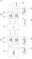
- FIG. 1 is a view illustrating an initial driving device of a solid-state transformer according to one embodiment of the present invention
- FIG. 2 is a detailed graph for describing FIG. 1 in detail.
- the initial driving device of the solid-state transformer is composed of an alternating current (AC)/direct current (DC) converter 100 which converts system power to direct current, a high voltage converter 200 which converts the output of the AC/DC converter 100 to a high voltage, a medium frequency transformer (MFT) 300 which converts the output of the high voltage converter 200 to a low voltage, a low voltage converter 400 which converts the output of the MFT 300 to a charging voltage of an electric vehicle or battery 800, and a controller 600 configured to control the operations of the AC/DC converter 100, the high voltage converter 200, the MFT 300, and the low voltage converter 400.
- AC alternating current
- DC direct current
- the initial driving device of the solid-state transformer of the present invention may further include a first power supply 510 which supplies power to the AC/DC converter 100, a second power supply 520 which supplies power to the high voltage converter 200, and a third power supply 700 which supplies power to the low voltage converter 400 and the controller 600.
- the first power supply 510 and the second power supply 520 may operate with a voltage of a capacitor charged in the high voltage converter 200
- the third power supply 700 may operate with a voltage of a capacitor charged in the low voltage converter 400 charged from the battery 800. Further, the third power supply 700 may operate with a voltage charged in the battery 800 during an initial operation.
- the controller 600 charges the capacitors in the high voltage converter 200 and the low voltage converter 400 using the low voltage converter 400 connected to the battery 800 on the basis of the voltage charged in the battery 800 during the initial operation. Further, the controller 600 charges the capacitors in the high voltage converter 200 and the low voltage converter 400 from the system power during a normal operation.
- FIG. 2 is a graph for describing the operation of the initial driving device of the solid-state transformer in FIG. 1
- the controller 600 of the present invention charges a voltage V810 of the high voltage converter capacitor and a voltage V820 of the low voltage converter capacitor to an initial operating voltage in an initial charging section P910.
- the controller 600 requires time for the power of the high voltage converter 200 to be normalized in a power supply initialization section P920, and thus waits without performing charging of the voltage V810 of the high voltage converter capacitor and the voltage V820 of the low voltage converter capacitor until the initial operation is recognized.
- controller 600 performs the normal operation in a normal state control section P930 to charge the voltage V810 of the high voltage converter capacitor and the voltage V820 of the low voltage converter capacitor.
- the controller 600 charges the voltage V810 of the high voltage converter capacitor and the voltage V820 of the low voltage converter capacitor to the initial operating voltage in the initial charging section P910, and in this case, may charge the capacitors of a first DC/DC converter 210, a second DC/DC converter 220, and a third DC/DC converter 410 to the initial operating voltage using a fourth DC/DC converter 420 on the basis of the power of the battery 800.
- the controller 600 of the present invention waits without performing the charging of the voltage V810 of the high voltage converter capacitor and the voltage V820 of the low voltage converter capacitor until the initial operation of the high voltage converter 200 is recognized in the power supply initialization section P920 because a time delay until the first power supply 510 and the second power supply 520, which use the capacitor voltages charged to the initial operating voltage as operating power, normally operate is required.
- the controller 600 performs the normal operation in the normal state control section P930 to charge the voltage V810 of the high voltage converter capacitor and the voltage V820 of the low voltage converter capacitor when the first power supply 510 and the second power supply 520 normally operate.
- the charging of the voltage V810 of the high voltage converter capacitor and the voltage V820 of the low voltage converter capacitor is performed with system power, and when the capacitors are charged to the normal operation, the controller 600 maintains normal operation in a normal state reaching section P940.
- the above-described initial driving device of the solid-state transformer according to the present invention may reduce the overall number of solid-state transformer components and improve system reliability by charging an internal capacitor of the solid-state transformer using the existing battery 800 instead of a separate external power source.
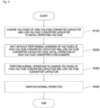
- FIG. 3 is an operation flow chart illustrating an initial driving method of the solid-state transformer according to one embodiment of the present invention.
- the initial driving method of the solid-state transformer includes an operation S100 of charging, by the controller 600 of the initial driving device of the solid-state transformer, the voltage V810 of the high voltage converter capacitor and the voltage V820 of the low voltage converter capacitor to the initial operating voltage, an operation S200 of waiting, by the controller 600, without performing the charging of the voltage V810 of the high voltage converter capacitor and the voltage V820 of the low voltage converter capacitor until the initial operation of the high voltage converter 200 is recognized, an operation S300 of performing, by the controller 600, a normal operation to charge the voltage V810 of the high voltage converter capacitor and the voltage V820 of the low voltage converter capacitor, and an operation S400 of maintaining, by the controller 600, the normal operation.
- the controller 600 charges the voltage V810 of the high voltage converter capacitor and the voltage V820 of the low voltage converter capacitor to the initial operating voltage in the initial charging operation S100, and in this case, may charge the capacitors of the first DC/DC converter 210, the second DC/DC converter 220, and the third DC/DC converter 410 to the initial operating voltage using the fourth DC/DC converter 420 on the basis of the power of the battery 800.
- the controller 600 of the present invention waits without performing the charging of the voltage V810 of the high voltage converter capacitor and the voltage V820 of the low voltage converter capacitor until the initial operation of the high voltage converter 200 is recognized in the power supply initialization operation S200 because a time delay until the first power supply 510 and the second power supply 520, which use the capacitor voltages charged to the initial operating voltage as operating power, normally operate is required.
- the controller 600 performs the normal operation in the normal state control operation S300 to charge the voltage V810 of the high voltage converter capacitor and the voltage V820 of the low voltage converter capacitor when the first power supply 510 and the second power supply 520 normally operate.
- the charging of the voltage V810 of the high voltage converter capacitor and the voltage V820 of the low voltage converter capacitor is performed with system power, and when the capacitors are charged to the normal operation, the controller 600 maintains the normal operation in the normal state reaching operation S400.
- the overall number of solid-state transformer components may be reduced and system reliability may be improved by charging the internal capacitor of the solid-state transformer using an existing battery instead of a separate external power source.
- the initial driving device and method of the solid-state transformer according to the present invention can charge the internal capacitor of the solid-state transformer by itself without a separate external power source, and can reduce the overall number of solid-state transformer components and improve system reliability by charging the internal capacitor of the solid-state transformer using an existing battery instead of a separate external power source.
- the present invention relates to initial driving device and method of a solid-state transformer, and may be used in the solid-state transformer field.
Landscapes
- Engineering & Computer Science (AREA)
- Power Engineering (AREA)
- Transportation (AREA)
- Mechanical Engineering (AREA)
- Chemical & Material Sciences (AREA)
- Electrochemistry (AREA)
- General Chemical & Material Sciences (AREA)
- Chemical Kinetics & Catalysis (AREA)
- Manufacturing & Machinery (AREA)
- Microelectronics & Electronic Packaging (AREA)
- Life Sciences & Earth Sciences (AREA)
- Sustainable Development (AREA)
- Sustainable Energy (AREA)
- Dc-Dc Converters (AREA)
Abstract
Description
- The present invention relates to initial driving device and method of a solid-state transformer, and more specifically, to performing stable initial driving of a solid-state transformer.
- Generally, in order to charge a vehicle battery of an electric vehicle, a voltage of 60 Hz, 25 kV is stepped down using a transformer to convert the voltage to a direct current (DC) voltage of a predetermined size for charging. The transformer and alternating current (AC)/DC converter account for a lot of weight, and are components that require weight reduction.
- Specifically, since a main transformer operates at a low frequency of 60 Hz, a value of inductance required for impedance matching is large, and thus many transformer windings should be wound or a lot of iron cores should be used, so that a weight and a volume are large and power density is relatively low.
- Accordingly, much studies have been conducted to reduce the weight of transformers and AC/DC converters operating at commercial frequencies, and in one of the studies, the weight and volume of the transformer are reduced using a semiconductor element to raise an operating frequency of the transformer to several kHz to several tens of kHz, which is a frequency much greater than 60 Hz.
- Like the above, a device that converts low-frequency high-voltage input power to high-frequency voltage/current using a semiconductor element, and then converts the high-frequency voltage/current to a low DC voltage required for a vehicle after passing through a high-frequency transformer is referred to as a solid-state transformer (SST) or an intelligent transformer.
- This solid-state transformer is gaining importance due to advantages such as a reduced system size, power quality compensation, and the like compared to existing low-frequency transformers, and research to perform stable initial operation has continued.
- For example, in
Korean Laid-Open Patent Publication No. 10-2017-0054340 - However, even in this case, there is a disadvantage in that an external power source should be separately applied for initial charging.
- The present invention is directed to providing an initial driving device and method of a solid-state transformer capable of charging an internal capacitor of a solid-state transformer by itself without a separate external power source.
- The present invention is directed to providing an initial driving device and method of a solid-state transformer capable of reducing the overall number of solid-state transformer components and improving system reliability by charging an internal capacitor of the solid-state transformer using an existing battery instead of a separate external power source.
- One aspect of the present invention provides an initial driving device of a solid-state transformer including an alternating current (AC)/direct current (DC) converter configured to convert system power to direct current, a high voltage converter configured to convert an output of the AC/DC converter to a high voltage, a medium frequency transformer (MFT) configured to convert an output of the high voltage converter to a low voltage, a low voltage converter configured to convert an output of the MFT to a charging voltage of an electric vehicle or battery, and a controller configured to control operations of the AC/DC converter, the high voltage converter, the MFT, and the low voltage converter.
- Here, the initial driving device of the solid-state transformer may further include a first power supply configured to supply power to the AC/DC converter, a second power supply configured to supply power to the high voltage converter, and a third power supply configured to supply power to the low voltage converter and the controller.
- Further, the first power supply and the second power supply may operate with a voltage of a capacitor charged in the high voltage converter.
- Here, the third power supply may operate with a voltage of a capacitor charged in the low voltage converter configured to charge the battery.
- Further, the third power supply may operate with a voltage charged in the battery during an initial operation.
- Here, the controller may charge the capacitors in the high voltage converter and the low voltage converter using the low voltage converter connected to the battery on the basis of the voltage charged in the battery during the initial operation, and may charge the capacitors in the high voltage converter and the low voltage converter from system power during normal operation.
- Further, the controller may charge a voltage of a high voltage converter capacitor and a voltage of a low voltage converter capacitor to an initial operating voltage in an initial charging section.
- Here, the controller may require time for power of the high voltage converter to be normalized in a power supply initialization section, and thus may wait without performing charging of the voltage of the high voltage converter capacitor and the voltage of the low voltage converter capacitor until the initial operation is recognized.
- Further, the controller may perform the normal operation in a normal state control section to charge the voltage of the high voltage converter capacitor and the voltage of the low voltage converter capacitor.
- In addition, the controller may maintain the normal operation in a normal state reaching section.
- Another aspect of the present invention provides an initial driving method of a solid-state transformer including an initial charging operation of charging, by a controller, a voltage of a high voltage converter capacitor and a voltage of a low voltage converter capacitor to an initial operating voltage, a power supply initialization operation of waiting, by the controller, without performing charging of the voltage of the high voltage converter capacitor and the voltage of the low voltage converter capacitor until an initial operation of a high voltage converter is recognized, a normal state control operation of performing, by the controller, normal operation to charge the voltage of the high voltage converter capacitor and the voltage of the low voltage converter capacitor, and a normal state reaching operation of maintaining, by the controller, a normal operation.
- An initial driving device and method of a solid-state transformer according to the present invention has an advantage of being capable of charging an internal capacitor of a solid-state transformer by itself without a separate external power source.
- Further, the initial driving device and method of the solid-state transformer according to the present invention has an advantage of being capable of reducing the overall number of solid-state transformer components and improving system reliability by charging the internal capacitor of the solid-state transformer using an existing battery instead of a separate external power source.
-
-
FIG. 1 is a view illustrating an initial driving device of a solid-state transformer according to one embodiment of the present invention. -
FIG. 2 is a graph for describing the operation of the initial driving device of the solid-state transformer inFIG. 1 . -
FIG. 3 is an operation flow chart illustrating an initial driving method of the solid-state transformer according to one embodiment of the present invention. - Specific embodiments for carrying out the present invention will be described with reference to the accompanying drawings.
- Since the present invention may be variously changed and have various embodiments, specific embodiments will be exemplified in the drawings and described in detail in the detailed description. This is not intended to limit the present invention to specific embodiments, and it may be understood that all changes, equivalents, and substitutions included in the spirit and technical scope of the present invention are included.
- Hereinafter, an initial driving device and method of a solid-state transformer according to the present invention will be described in detail with reference to the accompanying drawings.
-
FIG. 1 is a view illustrating an initial driving device of a solid-state transformer according to one embodiment of the present invention, andFIG. 2 is a detailed graph for describingFIG. 1 in detail. - Hereinafter, the initial driving device of the solid-state transformer according to one embodiment of the present invention will be described with reference to
FIGS. 1 and2 . - First, referring to
FIG. 1 , the initial driving device of the solid-state transformer according to one embodiment of the present invention is composed of an alternating current (AC)/direct current (DC)converter 100 which converts system power to direct current, ahigh voltage converter 200 which converts the output of the AC/DC converter 100 to a high voltage, a medium frequency transformer (MFT) 300 which converts the output of thehigh voltage converter 200 to a low voltage, alow voltage converter 400 which converts the output of theMFT 300 to a charging voltage of an electric vehicle orbattery 800, and acontroller 600 configured to control the operations of the AC/DC converter 100, thehigh voltage converter 200, theMFT 300, and thelow voltage converter 400. - Here, the initial driving device of the solid-state transformer of the present invention may further include a
first power supply 510 which supplies power to the AC/DC converter 100, asecond power supply 520 which supplies power to thehigh voltage converter 200, and athird power supply 700 which supplies power to thelow voltage converter 400 and thecontroller 600. - In this case, the
first power supply 510 and thesecond power supply 520 may operate with a voltage of a capacitor charged in thehigh voltage converter 200, and thethird power supply 700 may operate with a voltage of a capacitor charged in thelow voltage converter 400 charged from thebattery 800. Further, thethird power supply 700 may operate with a voltage charged in thebattery 800 during an initial operation. - Meanwhile, the
controller 600 charges the capacitors in thehigh voltage converter 200 and thelow voltage converter 400 using thelow voltage converter 400 connected to thebattery 800 on the basis of the voltage charged in thebattery 800 during the initial operation. Further, thecontroller 600 charges the capacitors in thehigh voltage converter 200 and thelow voltage converter 400 from the system power during a normal operation. -
FIG. 2 is a graph for describing the operation of the initial driving device of the solid-state transformer inFIG. 1 - As shown in
FIG. 2 , thecontroller 600 of the present invention charges a voltage V810 of the high voltage converter capacitor and a voltage V820 of the low voltage converter capacitor to an initial operating voltage in an initial charging section P910. - Here, the
controller 600 requires time for the power of thehigh voltage converter 200 to be normalized in a power supply initialization section P920, and thus waits without performing charging of the voltage V810 of the high voltage converter capacitor and the voltage V820 of the low voltage converter capacitor until the initial operation is recognized. - Further, the
controller 600 performs the normal operation in a normal state control section P930 to charge the voltage V810 of the high voltage converter capacitor and the voltage V820 of the low voltage converter capacitor. - In the present invention, the
controller 600 charges the voltage V810 of the high voltage converter capacitor and the voltage V820 of the low voltage converter capacitor to the initial operating voltage in the initial charging section P910, and in this case, may charge the capacitors of a first DC/DC converter 210, a second DC/DC converter 220, and a third DC/DC converter 410 to the initial operating voltage using a fourth DC/DC converter 420 on the basis of the power of thebattery 800. - Thereafter, the
controller 600 of the present invention waits without performing the charging of the voltage V810 of the high voltage converter capacitor and the voltage V820 of the low voltage converter capacitor until the initial operation of thehigh voltage converter 200 is recognized in the power supply initialization section P920 because a time delay until thefirst power supply 510 and thesecond power supply 520, which use the capacitor voltages charged to the initial operating voltage as operating power, normally operate is required. - Thereafter, the
controller 600 performs the normal operation in the normal state control section P930 to charge the voltage V810 of the high voltage converter capacitor and the voltage V820 of the low voltage converter capacitor when thefirst power supply 510 and thesecond power supply 520 normally operate. - In this case, the charging of the voltage V810 of the high voltage converter capacitor and the voltage V820 of the low voltage converter capacitor is performed with system power, and when the capacitors are charged to the normal operation, the
controller 600 maintains normal operation in a normal state reaching section P940. - The above-described initial driving device of the solid-state transformer according to the present invention may reduce the overall number of solid-state transformer components and improve system reliability by charging an internal capacitor of the solid-state transformer using the existing
battery 800 instead of a separate external power source. -
FIG. 3 is an operation flow chart illustrating an initial driving method of the solid-state transformer according to one embodiment of the present invention. - As shown in
FIG. 3 , the initial driving method of the solid-state transformer according to the present invention includes an operation S100 of charging, by thecontroller 600 of the initial driving device of the solid-state transformer, the voltage V810 of the high voltage converter capacitor and the voltage V820 of the low voltage converter capacitor to the initial operating voltage, an operation S200 of waiting, by thecontroller 600, without performing the charging of the voltage V810 of the high voltage converter capacitor and the voltage V820 of the low voltage converter capacitor until the initial operation of thehigh voltage converter 200 is recognized, an operation S300 of performing, by thecontroller 600, a normal operation to charge the voltage V810 of the high voltage converter capacitor and the voltage V820 of the low voltage converter capacitor, and an operation S400 of maintaining, by thecontroller 600, the normal operation. - Here, the
controller 600 charges the voltage V810 of the high voltage converter capacitor and the voltage V820 of the low voltage converter capacitor to the initial operating voltage in the initial charging operation S100, and in this case, may charge the capacitors of the first DC/DC converter 210, the second DC/DC converter 220, and the third DC/DC converter 410 to the initial operating voltage using the fourth DC/DC converter 420 on the basis of the power of thebattery 800. - Thereafter, the
controller 600 of the present invention waits without performing the charging of the voltage V810 of the high voltage converter capacitor and the voltage V820 of the low voltage converter capacitor until the initial operation of thehigh voltage converter 200 is recognized in the power supply initialization operation S200 because a time delay until thefirst power supply 510 and thesecond power supply 520, which use the capacitor voltages charged to the initial operating voltage as operating power, normally operate is required. - The
controller 600 performs the normal operation in the normal state control operation S300 to charge the voltage V810 of the high voltage converter capacitor and the voltage V820 of the low voltage converter capacitor when thefirst power supply 510 and thesecond power supply 520 normally operate. - In this case, the charging of the voltage V810 of the high voltage converter capacitor and the voltage V820 of the low voltage converter capacitor is performed with system power, and when the capacitors are charged to the normal operation, the
controller 600 maintains the normal operation in the normal state reaching operation S400. - In the above-described initial driving method of the solid-state transformer according to the present invention, the overall number of solid-state transformer components may be reduced and system reliability may be improved by charging the internal capacitor of the solid-state transformer using an existing battery instead of a separate external power source.
- Like the above, the initial driving device and method of the solid-state transformer according to the present invention can charge the internal capacitor of the solid-state transformer by itself without a separate external power source, and can reduce the overall number of solid-state transformer components and improve system reliability by charging the internal capacitor of the solid-state transformer using an existing battery instead of a separate external power source.
- The above description includes examples of one or more embodiments. Of course, it is not possible to describe all possible combinations of components or methods to describe the above-described embodiments, and it may be recognized by those skilled in the art that additional combinations and substitutions are possible. Accordingly, the described embodiments include all alternatives, modifications, and alterations that fall within the spirit and scope of the appended claims.
- The present invention relates to initial driving device and method of a solid-state transformer, and may be used in the solid-state transformer field.
Claims (11)
- An initial driving device of a solid-state transformer, comprising:an alternating current (AC)/direct current (DC) converter configured to convert system power to direct current;a high voltage converter configured to convert an output of the AC/DC converter to a high voltage;a medium frequency transformer (MFT) configured to convert an output of the high voltage converter to a low voltage;a low voltage converter configured to convert an output of the MFT to a charging voltage of an electric vehicle or battery; anda controller configured to control operations of the AC/DC converter, the high voltage converter, the MFT, and the low voltage converter.
- The initial driving device of claim 1, further comprising:a first power supply configured to supply power to the AC/DC converter;a second power supply configured to supply power to the high voltage converter; anda third power supply configured to supply power to the low voltage converter and the controller.
- The initial driving device of claim 2, wherein the first power supply and the second power supply operate with a voltage of a capacitor charged in the high voltage converter.
- The initial driving device of claim 2, wherein the third power supply operates with a voltage of a capacitor charged in the low voltage converter configured to charge the battery.
- The initial driving device of claim 2, wherein the third power supply operates with a voltage charged in the battery during an initial operation.
- The initial driving device of claim 1, wherein the controller charges capacitors in the high voltage converter and the low voltage converter using the low voltage converter connected to the battery on the basis of the voltage charged in the battery during an initial operation, and charges the capacitors in the high voltage converter and the low voltage converter from system power during a normal operation.
- The initial driving device of claim 1, wherein the controller charges a voltage of a high voltage converter capacitor and a voltage of a low voltage converter capacitor to an initial operating voltage in an initial charging section.
- The initial driving device of claim 1, wherein the controller requires time for power of the high voltage converter to be normalized in a power supply initialization section, and thus waits without performing charging of a voltage of a high voltage converter capacitor and a voltage of a low voltage converter capacitor until an initial operation is recognized.
- The initial driving device of claim 1, wherein the controller performs a normal operation in a normal state control section to charge a voltage of a high voltage converter capacitor and a voltage of a low voltage converter capacitor.
- The initial driving device of claim 1, wherein the controller maintains a normal operation in a normal state reaching section.
- An initial driving method of a solid-state transformer as a driving method of the solid-state transformer, comprising:an initial charging operation of charging, by a controller, a voltage of a high voltage converter capacitor and a voltage of a low voltage converter capacitor to an initial operating voltage;a power supply initialization operation of waiting, by the controller, without performing charging of the voltage of the high voltage converter capacitor and the voltage of the low voltage converter capacitor until an initial operation of a high voltage converter is recognized;a normal state control operation of performing, by the controller, a normal operation to charge the voltage of the high voltage converter capacitor and the voltage of the low voltage converter capacitor; anda normal state reaching operation of maintaining, by the controller, a normal operation.
Applications Claiming Priority (2)
| Application Number | Priority Date | Filing Date | Title |
|---|---|---|---|
| KR1020220081364A KR102714661B1 (en) | 2022-07-01 | 2022-07-01 | Apparatus for initial driving of solid state transformer and method thereof |
| PCT/KR2022/015254 WO2024005266A1 (en) | 2022-07-01 | 2022-10-11 | Initial driving device and method for solid-state transformer |
Publications (2)
| Publication Number | Publication Date |
|---|---|
| EP4550650A1 true EP4550650A1 (en) | 2025-05-07 |
| EP4550650A4 EP4550650A4 (en) | 2026-04-29 |
Family
ID=89380814
Family Applications (1)
| Application Number | Title | Priority Date | Filing Date |
|---|---|---|---|
| EP22946031.6A Pending EP4550650A4 (en) | 2022-07-01 | 2022-10-11 | STARTING DRIVE DEVICE AND METHOD FOR A SOLID BODY TRANSFORMER |
Country Status (4)
| Country | Link |
|---|---|
| US (1) | US20250083543A1 (en) |
| EP (1) | EP4550650A4 (en) |
| KR (1) | KR102714661B1 (en) |
| WO (1) | WO2024005266A1 (en) |
Family Cites Families (8)
| Publication number | Priority date | Publication date | Assignee | Title |
|---|---|---|---|---|
| KR101620441B1 (en) | 2009-06-17 | 2016-05-24 | 주식회사 아리스케일 | Method for multiple interpolation filters, and apparatus for encoding by using the same |
| JP6149207B2 (en) * | 2011-07-19 | 2017-06-21 | 富士電機株式会社 | Initial charging device for power converter |
| JP2015015829A (en) * | 2013-07-04 | 2015-01-22 | 住友電気工業株式会社 | Bidirectional ac/dc conversion device, inrush current prevention method and computer program |
| US9673695B1 (en) * | 2016-05-24 | 2017-06-06 | Eaton Corporation | System and method for intelligent circuit breaking in adjustable speed drives |
| KR101873113B1 (en) * | 2016-10-21 | 2018-08-02 | 한국전력공사 | Startup method of semiconductor transformer using subsidiary power and dc/dc converter |
| EP3796528B1 (en) * | 2019-09-20 | 2023-12-27 | ABB Schweiz AG | Current balancing in power semiconductors of a dc/dc converter |
| CN111342676B (en) * | 2020-03-17 | 2025-09-23 | 深圳威迈斯新能源(集团)股份有限公司 | A pre-chargeable DCDC conversion circuit |
| KR102450195B1 (en) * | 2020-11-12 | 2022-10-04 | 효성중공업 주식회사 | Startup method for Solid State Transformer and Converter using the same |
-
2022
- 2022-07-01 KR KR1020220081364A patent/KR102714661B1/en active Active
- 2022-10-11 US US18/571,730 patent/US20250083543A1/en active Pending
- 2022-10-11 EP EP22946031.6A patent/EP4550650A4/en active Pending
- 2022-10-11 WO PCT/KR2022/015254 patent/WO2024005266A1/en not_active Ceased
Also Published As
| Publication number | Publication date |
|---|---|
| KR102714661B1 (en) | 2024-10-15 |
| EP4550650A4 (en) | 2026-04-29 |
| US20250083543A1 (en) | 2025-03-13 |
| KR20240003592A (en) | 2024-01-09 |
| WO2024005266A1 (en) | 2024-01-04 |
Similar Documents
| Publication | Publication Date | Title |
|---|---|---|
| US11296533B2 (en) | Vehicle power supply device | |
| US20250167694A1 (en) | Switched capacitors for ac-dc applications | |
| JP2018148637A (en) | Charger and on-vehicle power supply | |
| KR100902507B1 (en) | Power control device and its operation method | |
| WO2015004948A1 (en) | Discharge control device | |
| US11387666B2 (en) | Dual stage battery charger | |
| EP4358382A1 (en) | Systems and methods for integrated boost in high voltage and low voltage power conversion for battery charger | |
| KR101717082B1 (en) | Bi-directional battery charger for an electric vehicle using cascaded transformers | |
| JP2017022805A (en) | Electric car | |
| KR20210018598A (en) | Electric power conversion system and control method therefor | |
| JPH07322524A (en) | Power supply circuit | |
| CN104247242A (en) | Output stage of a charging device | |
| US12525821B2 (en) | Wireless power transfer facility | |
| US12368367B2 (en) | Startup method of semiconductor transformer, and converter using same | |
| US9853551B2 (en) | Isolated DC-DC power conversion circuit | |
| US20250083543A1 (en) | Initial driving device and method of solid-state transformer | |
| JP2025181921A (en) | Charging device and charging method | |
| JP2013034279A (en) | Multi-phase converter circuit | |
| KR101190676B1 (en) | Bettary Quick charging device | |
| KR20200094810A (en) | Dc-dc converter for electric vehicle | |
| EP1870276A1 (en) | Electric vehicle control apparatus | |
| JP2021002902A (en) | Charger | |
| EP4712326A1 (en) | Ac/dc converter with 3-1 phase matrix converter, transformer, active rectifier and power compensation circuit for single-phase operation | |
| CN111193312A (en) | Charger and charging method | |
| EP4712324A1 (en) | Ac/dc converter with 3-1 phase matrix converter, transformer, active rectifier and power compensation circuit for single-phase operation |
Legal Events
| Date | Code | Title | Description |
|---|---|---|---|
| STAA | Information on the status of an ep patent application or granted ep patent |
Free format text: STATUS: UNKNOWN |
|
| STAA | Information on the status of an ep patent application or granted ep patent |
Free format text: STATUS: THE INTERNATIONAL PUBLICATION HAS BEEN MADE |
|
| PUAI | Public reference made under article 153(3) epc to a published international application that has entered the european phase |
Free format text: ORIGINAL CODE: 0009012 |
|
| STAA | Information on the status of an ep patent application or granted ep patent |
Free format text: STATUS: REQUEST FOR EXAMINATION WAS MADE |
|
| 17P | Request for examination filed |
Effective date: 20231218 |
|
| AK | Designated contracting states |
Kind code of ref document: A1 Designated state(s): AL AT BE BG CH CY CZ DE DK EE ES FI FR GB GR HR HU IE IS IT LI LT LU LV MC ME MK MT NL NO PL PT RO RS SE SI SK SM TR |
|
| DAV | Request for validation of the european patent (deleted) | ||
| DAX | Request for extension of the european patent (deleted) | ||
| REG | Reference to a national code |
Ref country code: DE Ref legal event code: R079 Free format text: PREVIOUS MAIN CLASS: H02M0001360000 Ipc: B60L0053220000 |
|
| A4 | Supplementary search report drawn up and despatched |
Effective date: 20260331 |
|
| RIC1 | Information provided on ipc code assigned before grant |
Ipc: B60L 53/22 20190101AFI20260325BHEP Ipc: B60L 53/14 20190101ALI20260325BHEP Ipc: B60L 58/20 20190101ALI20260325BHEP Ipc: H02M 1/36 20070101ALI20260325BHEP Ipc: H02M 3/07 20060101ALI20260325BHEP Ipc: H02J 7/02 20160101ALI20260325BHEP Ipc: H01M 10/42 20060101ALI20260325BHEP Ipc: H01M 10/44 20060101ALI20260325BHEP |