EP4550581A1 - Electrical device having wire installation mechanism - Google Patents
Electrical device having wire installation mechanism Download PDFInfo
- Publication number
- EP4550581A1 EP4550581A1 EP24202840.5A EP24202840A EP4550581A1 EP 4550581 A1 EP4550581 A1 EP 4550581A1 EP 24202840 A EP24202840 A EP 24202840A EP 4550581 A1 EP4550581 A1 EP 4550581A1
- Authority
- EP
- European Patent Office
- Prior art keywords
- release lever
- terminal
- wire
- external tool
- release
- Prior art date
- Legal status (The legal status is an assumption and is not a legal conclusion. Google has not performed a legal analysis and makes no representation as to the accuracy of the status listed.)
- Pending
Links
- 238000009434 installation Methods 0.000 title description 26
- 230000007246 mechanism Effects 0.000 title description 5
- 230000014759 maintenance of location Effects 0.000 claims description 14
- 238000013265 extended release Methods 0.000 claims description 11
- 238000003780 insertion Methods 0.000 description 4
- 230000037431 insertion Effects 0.000 description 4
- 230000000712 assembly Effects 0.000 description 2
- 238000000429 assembly Methods 0.000 description 2
- 230000008901 benefit Effects 0.000 description 2
- 239000002184 metal Substances 0.000 description 2
- 230000004048 modification Effects 0.000 description 2
- 238000012986 modification Methods 0.000 description 2
- 230000009471 action Effects 0.000 description 1
- 238000000576 coating method Methods 0.000 description 1
- 239000004020 conductor Substances 0.000 description 1
- 239000007769 metal material Substances 0.000 description 1
- 230000008439 repair process Effects 0.000 description 1
- 230000000717 retained effect Effects 0.000 description 1
- 230000035939 shock Effects 0.000 description 1
- 239000007787 solid Substances 0.000 description 1
- 238000004381 surface treatment Methods 0.000 description 1
Images






Classifications
-
- H—ELECTRICITY
- H01—ELECTRIC ELEMENTS
- H01R—ELECTRICALLY-CONDUCTIVE CONNECTIONS; STRUCTURAL ASSOCIATIONS OF A PLURALITY OF MUTUALLY-INSULATED ELECTRICAL CONNECTING ELEMENTS; COUPLING DEVICES; CURRENT COLLECTORS
- H01R4/00—Electrically-conductive connections between two or more conductive members in direct contact, i.e. touching one another; Means for effecting or maintaining such contact; Electrically-conductive connections having two or more spaced connecting locations for conductors and using contact members penetrating insulation
- H01R4/28—Clamped connections, spring connections
- H01R4/48—Clamped connections, spring connections utilising a spring, clip, or other resilient member
- H01R4/4809—Clamped connections, spring connections utilising a spring, clip, or other resilient member using a leaf spring to bias the conductor toward the busbar
- H01R4/4828—Spring-activating arrangements mounted on or integrally formed with the spring housing
- H01R4/4833—Sliding arrangements, e.g. sliding button
-
- H—ELECTRICITY
- H01—ELECTRIC ELEMENTS
- H01H—ELECTRIC SWITCHES; RELAYS; SELECTORS; EMERGENCY PROTECTIVE DEVICES
- H01H1/00—Contacts
- H01H1/58—Electric connections to or between contacts; Terminals
- H01H1/5844—Electric connections to or between contacts; Terminals making use of wire-gripping clips or springs
-
- H—ELECTRICITY
- H01—ELECTRIC ELEMENTS
- H01R—ELECTRICALLY-CONDUCTIVE CONNECTIONS; STRUCTURAL ASSOCIATIONS OF A PLURALITY OF MUTUALLY-INSULATED ELECTRICAL CONNECTING ELEMENTS; COUPLING DEVICES; CURRENT COLLECTORS
- H01R4/00—Electrically-conductive connections between two or more conductive members in direct contact, i.e. touching one another; Means for effecting or maintaining such contact; Electrically-conductive connections having two or more spaced connecting locations for conductors and using contact members penetrating insulation
- H01R4/28—Clamped connections, spring connections
- H01R4/48—Clamped connections, spring connections utilising a spring, clip, or other resilient member
- H01R4/4809—Clamped connections, spring connections utilising a spring, clip, or other resilient member using a leaf spring to bias the conductor toward the busbar
- H01R4/48185—Clamped connections, spring connections utilising a spring, clip, or other resilient member using a leaf spring to bias the conductor toward the busbar adapted for axial insertion of a wire end
- H01R4/4819—Clamped connections, spring connections utilising a spring, clip, or other resilient member using a leaf spring to bias the conductor toward the busbar adapted for axial insertion of a wire end the spring shape allowing insertion of the conductor end when the spring is unbiased
Definitions
- the present invention generally relates to the field of switch plate assembly. More specifically, the present invention related to an electrical device having convenient wiring provisions for wall switches, sockets, receptacles and the like.
- switch or socket plates are generally made with visible screws. However, switch or socket plates having mounting screws visible are not mostly likable, especially switch or socket plates made of metal with decorative surface treatments. Due to the structural limitation of conventional switch or socket plate assemblies are commonly made of plastic to hide mounting screws. Most of the conventional switch plate assemblies are either made of non-metallic materials to hide mounting screws or made of metal with exposed mounting screws on front surfaces.
- a terminal spring and release lever parts are main components of such conventional screwless installation system.
- the terminal spring is provided inside a switch or socket assembly which rigidly holds stripped solid or flexible wire and providing anti reversing arrester for the wire.
- the release lever is provided outside of the switch or socket assembly and accessible by hand to actuate the terminal spring to take out the wire from the switch or socket assembly. The breakage of the release lever happens when unavoidable drop or accident of the switch or socket assembly.
- the principal object of the embodiments herein is to provide electrical device for wall switches, sockets, receptacles and the like.
- the proposed electrical device ensures rigid wire termination, hassle free installation and eliminates discontinuity of the current to appliances to provide safe and secured installation system to the users.
- One particular object of the embodiments herein is to provide the electrical device that provides easy insertion of stripped wire with covered and tool operated release lever in the switch or socket assembly to reduced installation time.
- Yet another object of the embodiments herein is to provide release levers in different shape and size eliminates the existing problem and ensure safe and durable operation.
- the different size of stripped wires with respect to operating current of the switch or socket is entered through the different size of wire entry holes in switch base case of the electrical device.
- Yet another object of the embodiments herein is to perform sliding operation of release levers using an external tool like screw driver.
- the external tool is guided to head touch the release lever and pushes the release lever to perform the sliding operation over a terminal spring. Further, the sliding operation of the release lever pushes the terminal spring downwards to create a gap between the terminal spring and the terminal cage.
- the present invention provides an electrical device having hassle free provisions for electrical wire installation.
- the electrical device includes a rocker assembly, a switch assembly connected to the rocker assembly and a plunger connected to the rocker assembly and the switch assembly.
- the rocker assembly includes an outer rocker, and an inner rocker connected to the outer rocker.
- the switch assembly includes a plurality of release levers, a switch top case, a switch base case, a switch base case having an external tool slot connected to the plurality of release levers and a wire entry slot adapted to receive a stripped wire, a terminal cage with a terminal spring connected to the plurality of release levers, a common terminal connected to the terminal cage, and a moving terminal connected between the common terminal and the plunger.
- An external tool is guided to perform a sliding operation over the terminal spring.
- the sliding operation of the release lever pushes the terminal spring downwards to create a gap between the terminal spring and the terminal cage.
- the stripped wire has contact with the terminal spring.
- the stripped wire slips on head of the terminal spring and pushes the terminal spring down to enter inside to terminal cage until stopped by a length of the stripped wire.
- the inner rocker includes flexible arms each of which compress terminal pressure points, a rectangular slot for the terminal cage connected between the flexible arms, a circular slot for screw entry, a lever slot for the release lever, a top wire stopper connected to the rectangular slot, side wire stoppers connected to the top wire stopper, and a wire squeezer punch profile connected to rectangular slot.
- the wire squeezer punch profile squeezes and holds of the stripped wire.
- the stripped wire has contact with the terminal spring.
- the stripped wire slips on head of the terminal spring and pushes the terminal spring down to enter inside to terminal cage until stopped by the top wire stopper or side wire stoppers.
- the plurality of release levers comprises a floating release lever, a hanged release lever, and a pivoted head release lever.
- the floating release lever includes a wedge to receive the external tool on an inclined face and operating the external tool for releasing the stripped wire, a hammer head observes force exerted by the external tool and operates the terminal spring to release the stripped wire, a CAM Sliding profile member has sliding moment on the terminal spring, and a linear sliding profile member for sliding and retention of sliding axis of the release lever.
- the release lever slides over the terminal spring using the CAM Sliding profile member and the release lever slides over the terminal spring.
- the hanged lever includes a wedge to receive the external tool on an inclined face and operating the external tool for releasing the stripped wire, a hammer head observes force exerted by the external tool and operates the terminal spring to release the stripped wire, a CAM Sliding profile member has sliding moment on the terminal spring, a hanging hinge retention of the release lever after uninstallation of the stripped wire.
- the release lever slides over the terminal spring using the CAM Sliding profile member, and a support lever connected to the at least one release lever and the wedge.
- the hanging hinge is provided between the external tool slot and the common terminal, and the support lever provides support the at least one release lever based on a shape of the release lever, and the support lever comprises one of a straight profile and a zigzag profile.
- the pivoted head release lever includes a wedge to receive the external tool on an inclined face and operating the external tool for releasing the stripped wire, a hammer head observes force exerted by the external tool and operates the terminal spring to release the stripped wire, a CAM Sliding profile member has sliding moment on the terminal spring.
- the release lever slides over the terminal spring using the CAM Sliding profile member, a hanging hinge retention of the release lever after uninstallation of the stripped wire, a support lever connected to the release lever and the wedge, and a release lever movement stopper to stop movement of the release lever during the sliding operation.
- the hanging hinge is provided between the external tool slot and the common terminal.
- the support lever provides support the release lever based on a shape of the release lever.
- the support lever comprises one of a straight profile and a zigzag profile.
- the terminal spring is connected to an extended-release lever.
- the extended-release lever comprises a wire crushing profile.
- the outer rocker includes terminal holders provided at a centre plate of the outer rocker and a hold and support member provided at top and bottom of the outer rocker. The holder provides the sliding operation to the release lever in the switch assembly.
- the switch top case includes a release lever guide member that guides the release lever during a release operation of the stripped wire, and a release lever holder connected to the release lever guide.
- the release lever holder hinged between the switch base case and the common terminal.
- FIGS. 1 through 15 where similar reference characters denote corresponding features consistently throughout the figures, there are shown preferred implementations. Further, for the sake of simplicity, and without limitation, the same numbers are used throughout the drawings to reference like features and components. The implementations herein will be better understood from the following description with reference to the drawings.
- socket and switch are used interchangeably.
- the term socket can include only socket or socket with switch.
- the term switch can include only switch or switch with socket.
- FIGS. 1(a) and 2(a) illustrates an assembled view of an electrical device (2) fixed in a conventional mounting box (3) provided inside a mounting wall (1), according to embodiments as disclosed herein.
- the proposed electrical device (2) can be easily mounted inside the mounting conventional box (3) which are provided in the mounting wall (1).
- the proposed electrical device (2) can be a switch assembly (10) as shown in the
- FIGS. 1(b) and 2(b) illustrates an exploded view of the electrical device (2) fixed in the conventional mounting box (3) provided inside the mounting wall (1), accordingly to embodiments as disclosed herein.
- the conventional mounting box (3) adopted to be fixed inside the mounting wall.
- a fixing frame (4) is connected to the conventional mounting box (3) using mounting screws (5).
- the proposed electrical device (2) are adopted to be installed inside the conventional mounting box (3).
- a cover frame (6) is attached on surface of the mounting wall (1).
- the cover frame (6) is fixed on the fixing frame (4) to get better look.
- FIG. 3 illustrates a cross sectional view of the electrical device (2), accordingly to embodiments as disclosed herein.
- the electrical device (2) includes a rocker assembly (7), a switch assembly (10) (or referred as socket assembly (10)) connected to the rocker assembly (7), and a plunger (11) connected to the rocker assembly (7) and the switch assembly (10).
- the rocker assembly (7) comprising an outer rocker (8), and an inner rocker (9) connected to the outer rocker (8).
- the switch assembly (10) includes one or more release levers (12), a switch top case (13), a switch base case (14), a terminal cage (17), a common terminal (19), and a moving terminal (20).
- the switch base case (14) is connected to the switch top case (13).
- the switch base case (14) includes an external tool slot (15) connected to the one or more release levers (12) and wire entry slots (16) adapted to receive a stripped wire (21).
- the terminal cage (17) is provided with a terminal spring (18) connected to the plurality of release levers (12).
- the common terminal (19) is connected to the terminal cage (17).
- the moving terminal (20) is connected between the common terminal (19) and the plunger (11).
- An external tool (22) is guided to push the at least one release lever (12) of the plurality of release levers (12) and perform a sliding operation over the terminal spring (18).
- the wire entry slots (16) are provided in both screw and screwless assembly to guide and have wire the switch assembly (10) in distinct size based on the requirement of the operating current rating of the switch and socket.
- the stripped wire (21) has contact with the terminal spring (18) that slips on head of the terminal spring (18) and pushes the terminal spring (18) down to enter inside the terminal cage (17) until stopped by a length of the stripped wire (21).
- the sliding operation of the at least one release lever (12) pushes the terminal spring (18) downwards to create a gap between the terminal spring (18) and the terminal cage (17).
- the proposed disclosure provides the release levers (12), the terminal spring (18) and the contact terminals such as the common terminal (19) and the moving terminal (20) based solution to solve the existing problem and bringing better solution to the screwless installation.
- the release lever (12) has designed in distinctive style like a floating release lever (12), a hanged release lever (12), a hanged release lever (12), and a pivoted head release lever. All the variants of designs have kept in closed enclosure.
- These release levers (12) are assembled with switch/socket top and switch/socket base casing.
- the external tool slot (15) provided in all the switch/socket assembly in different direction/location to operate the release lever (12) by the external tool (22) like a screwdriver.
- the slots provided with respect to the different wire entries like top, back, front, or bottom and right or left side wire entries likewise the external tool (22) access and operation is one in the top, back, front, or bottom and the right or left side. Modification on the hinge of the release lever (12) is to make better interface with the parts in the switch or socket assembly (10).
- the release lever (12) is designed with wedge (31) to slide in the switch assembly (10) when operated with the external tool (22) and hammer head to press the terminal spring (18).
- the terminal spring (18) is designed with different profile to provide spring back action, wire holding with bended head to be pressed by head of the release lever (12) during the sliding operation.
- the contact terminals (19 and 20) are designed with different cross section and style to accommodate the release lever (12) and the terminal spring (18).
- the contact terminals (19 and 20) are compatible for both screw and screwless wire terminations.
- Features in the new contact terminals contact terminals (19 and 20) are designed with consideration of the conductive cross section of the terminals with current ratings. The same contact terminals (19 and 20) can used for different current ratings with coatings and different conductive material if required.
- new release levers (12) are designed, the terminal spring (18) and the contact terminals (19 and 20) with consideration of the functional requirements.
- the proposed disclosure ensures safety in assembly, the electrical device (2), and installation.
- the continuous current supply has delivered to the switch/socket and other functions.
- the installation time reduced and led the cost benefit to the end customer in terms of less installation time and replacing the damaged parts.
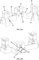
- FIG. 4(a) illustrates a front view of the inner rocker (9), according to embodiments disclosed herein.
- FIG. 4(b) illustrates a rear view of the inner rocker (9), according to embodiments disclosed herein.
- FIG. 4(c) illustrates a section view of the inner rocker (9), according to embodiments disclosed herein.
- the inner rocker (9) includes flexible arms (23), rectangular slot (24), circular slot (25), lever slot (26), top wire stopper (27), side wire stoppers (28), wire squeezer punch profile (29) and terminal pressure points (30).
- the flexible arms (23) each of which compress terminal pressure points.
- the rectangular slot (24) for the terminal cage (17) is connected between the flexible arms (23).
- the common contact terminal has provisions to the screwless terminal holding in the switch assembly (10).
- the circular slot (25) is used for screw entry.
- the common contact terminal has provisions to the screw terminal holding in the switch assembly (10).
- the lever slot (26) is for the at least one release lever.
- the lever slot (26) is to have the main member of the screwless mechanism called release lever which is used to release the wire during uninstallation or repair of the switch assembly (10).
- the top wire stopper (27) is connected to the rectangular slot (24) and is used to stop excessive of the stripped wire (21) in the switch assembly (10).
- the side wire stoppers (28) are connected to the top wire stopper (27). This feature stops and secures the switch assembly (10) from unavoidable touch between the stripped wire (21) and plastic parts in the switch assembly (10).
- the stripped wire (21) has contact with the terminal spring (18).
- the stripped wire (21) slips on head of the terminal spring (18) and pushes the terminal spring (18) down to enter inside to terminal cage (17) until stopped by the top wire stopper (27) or the side wire stoppers (28).
- the wire squeezer punch profile (29) is connected to rectangular slot (24).
- the wire squeezer punch profile (29) squeezes and holds of the stripped wire (21). This punch profile is used to squeeze and ensure robust holding of the stripped wire (21) in the screw and screwless installation.
- the proposed punch profile creates the different shape and curve in the installed stripped wire (21) to make more robust holding in the wire termination.
- FIGS. 5(a)-5(b) illustrates the floating release lever (12), according to embodiments disclosed herein.
- the floating release lever includes a wedge (31), a hammer head (32), a CAM sliding profile member (33), and a linear sliding profile member (34).
- the wedge (31) receives the external tool (22) on an inclined face and operating the external tool (22) for releasing the stripped wire (21).
- the wedge (31) acts as cam profile in the floating release lever. This receives the external tool (22) on its inclined face and operating the screwless terminal while releasing the stripped wire (21).
- the external tool slot (15) is used in the switch base case (14). The external tool slot (15) directs the external tool (22) to the wedge (31) of the release lever (12) and proving reactive force to the external tool (22) in the sliding operation.
- the hammer head (32) is connected to the wedge (31).
- the hammer head (32) observes force exerted by the external tool (22) and operates the terminal spring (18) to release the stripped wire (21).
- the hammer head (32) is a strongest portion in the part. This part observes operation force exerted by the external tool (22) and operates the terminal spring (18) to release the stripped wire (21).
- the CAM sliding profile member (33) is connected to the wedge (31) and the hammer head (32).
- the CAM sliding profile member (33) has sliding moment on the terminal spring (18).
- the release lever (12) slides over the terminal spring (18) using the CAM sliding profile member (33).
- the floating release lever exactly has cam shaped profile feature which has sliding moment on the terminal spring (18) and supports for the smooth operation during the wire uninstallation in the switch assembly (10).
- the linear sliding profile member (34) is provided for sliding and retention of sliding axis of the at least one release lever (12), wherein the release lever (12) slides over the terminal spring (18).
- the linear sliding profile is to be supported on the flat face of the base casing of the switch assembly (10).
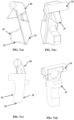
- FIG. 6(a) illustrates a perspective view of a hanged release lever with straight profile, according to embodiments disclosed herein.
- FIG. 6(b) illustrates a side view of the hanged release lever with straight profile, according to embodiments disclosed herein.
- the hanged release lever includes a wedge (31), a hammer head (32), a CAM sliding profile member (33), a hanging hinge (35) and a support lever (36).
- the wedge (31) receives the external tool (22) on an inclined face and operating the external tool (22) for releasing the stripped wire (21).
- the wedge (31) acts as cam profile in the hanged release lever. This receives the external tool (22) on its inclined face and operating the screwless terminal while releasing the stripped wire (21).
- the external tool slot (15) directs the external tool (22) to the wedge (31) of the release lever (12) and proving reactive force to the external tool (22) in the sliding operation.
- the hammer head (32) is connected to the wedge (31).
- the hammer head (32) observes force exerted by the external tool (22) and operates the terminal spring (18) to release the stripped wire (21).
- the hammer head (32) is a strongest portion in the part. This part observes operation force exerted by the external tool (22) and operates the terminal spring (18) to release the stripped wire (21).
- the CAM sliding profile member (33) is connected to the wedge (31) and the hammer head (32).
- the CAM sliding profile member (33) has sliding moment on the terminal spring (18).
- the release lever (12) slides over the terminal spring (18) using the CAM sliding profile member (33).
- the hanged release lever exactly has cam shaped profile feature which has sliding moment on the terminal spring (18) and supports for the smooth operation during the wire uninstallation in the switch assembly (10).
- the hanging hinge (35) is connected to the wedge (31).
- the hanging hinge (35) is provided for retention of the release lever (12) after uninstallation of the stripped wire (21).
- the hanging hinge (35) is provided between the external tool slot (15) and the common terminal (19). This feature hanged and acting as hinge to ensure the retention of the release lever (12) after the wire uninstallation in the switch assembly (10).
- the hanging hinge (35) is held between the switch top case (13) and the contact terminals (19 and 20).
- the support lever (36) is connected to the hanging hinge (35) and the wedge (31).
- the support lever (36) provides support the at least one release lever (12) based on a shape of the at least one release lever (12).
- the support lever (36) has a straight profile as shown in the FIG. 6(b) .
- the support lever (36) has a zigzag profile as shown in the FIGS. 6(c)-6(d).
- FIG. 6(c) illustrate a perspective view of a hanged release lever with zigzag profile, according to embodiments disclosed herein.
- FIG. 6(d) illustrates a side view of the hanged release lever with zigzag profile, according to embodiments disclosed herein.
- the support lever (36) brings the flexibility in the sliding operation of the release lever (12) and supporting the retention of the release lever (12). This feature may be the straight profile and other shape based on the requirement of flexibility to the sliding operation of the release lever (12).
- FIGS. 7(a)-7(d) illustrate a pivoted head release lever, according to embodiments disclosed herein.
- the pivoted head release lever includes a wedge (31), a hammer head (32), a CAM sliding profile member (33), a hanging hinge (35) a support lever (36), and a release lever movement stopper (37).
- the wedge (31), as indicated in FIG. 7(c) receives the external tool (22) on an inclined face and operating the external tool (22) for releasing the stripped wire (21).
- the wedge (31) acts as cam profile in the pivoted head release lever. This receives the external tool (22) on its inclined face and operating the screwless terminal while releasing the stripped wire (21).
- the external tool slot (15) directs the external tool (22) to the wedge (31) of the release lever (12) and proving reactive force to the external tool (22) in the sliding operation.
- the hammer head (32), as shown in FIGS. 7(a) and 7(c) is connected to the wedge (31).
- the hammer head (32) observes force exerted by the external tool (22) and operates the terminal spring (18) to release the stripped wire (21).
- the hammer head (32) is a strongest portion in the part. This part observes operation force exerted by the external tool (22) and operates the terminal spring (18) to release the stripped wire (21).
- the CAM sliding profile member (33) is connected to the wedge (31) and the hammer head (32).
- the CAM sliding profile member (33) has sliding moment on the terminal spring (18).
- the release lever (12) slides over the terminal spring (18) using the CAM sliding profile member (33).
- the pivoted head release lever exactly has cam shaped profile feature which has sliding moment on the terminal spring (18) and supports for the smooth operation during the wire uninstallation in the switch assembly (10).
- the hanging hinge (35) is provided for retention of the release lever (12) after uninstallation of the stripped wire (21).
- the hanging hinge (35) is provided between the external tool slot (15) and the common terminal (19). This feature hanged and acting as hinge to ensure the retention of the release lever (12) after the wire uninstallation in the switch assembly (10).
- the hanging hinge (35) is held between the switch top case (13) and the contact terminals (19 and 20).
- the support lever (36) is connected to the hanging hinge (35) and the wedge (31).
- the support lever (36) provides support the at least one release lever (12) based on a shape of the at least one release lever (12).
- the support lever (36) has a straight profile or any other shape based on the requirement of flexibility to operate the release lever (12).
- the support lever (36) brings the flexibility in the sliding operation of the release lever (12) and supporting the retention of the release lever (12). This feature may be the straight profile and other shape based on the requirement of flexibility to the sliding operation of the release lever (12).
- the release lever movement stopper (37) is connected to the hanging hinge (35).
- the release lever movement stopper (37) stops movement of the at least one release lever (12) during the sliding operation to make robustness in the function during the wire insertion. If the release lever movement stopper (37) is not provided the release lever (12) move in opposite direction downside to wire entry and there may be loss or collapse in the connection.
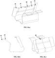
- FIGS. 8(a)-8(c) illustrates the terminal spring (18) is connected to an extended-release lever (38), according to embodiments as disclosed herein.
- the terminal spring (18) is connected to the extended-release lever (38) having a wire crushing profile (39) and a release lever sliding profile (40).
- the extended-release lever (38) reduces plastic part.
- the terminal spring (18) includes a locking profile (41) and push feature (42) to push wire upside to make robust fixation.
- the extended-release lever (38) is the extended portion of the terminal spring (18), and this feature reduces the one more part in the switch assembly (10) to release the stripped wire (21).
- the extended-release lever (38) can be accessed directly through the external tool slot (15) in the switch base case (14) to release the stripped wire (21).
- FIG. 9(a) illustrates a front view of the outer rocker (8), according to embodiments as disclosed herein.
- the outer rocker (8) includes a socket or switch centre plate (43).
- FIGS. 9(b)-9(c) illustrates a rear view of the outer rocker (8), according to embodiments as disclosed herein.
- the outer rocker (8) comprises terminal holders (44) and a hold and support member (45).
- the terminal holders (44) are provided at the centre plate (43) of the outer rocker (8).
- the terminal holders (44) provide the sliding operation to the at least one release lever (12) in the switch assembly (10).
- the hold and support member (45) are provided at top and bottom of the outer rocker (8). In an embodiment, the hold and support member (45) are provided for the hinged lever.
- the floating and hanging release levers supported and guided directly in the contact terminal slot. In order to provide better support from z axis the supports brought for the top and base casing of the socket assembly. This feature supports and provides the sliding operation to the release lever (12) in the screwless terminal assembly.
- FIG. 10 illustrates a front perspective view of the switch base case (14), according to embodiments as disclosed herein.
- the switch base case (14) includes the external tool slot (15) connected to the one or more release levers (12) and the wire entry slots (16) adapted to receive the stripped wire (21). To operate the release levers (12) in the safe with proper guidance these slots used in the switch base case (14).
- the external tool slot (15) slots direct the screwdriver to the wedge portion of the release lever (12) and proving reactive force to the screwdriver in the sliding operation.
- the wire entry slots (16) are there in both screw and screwless assembly to guide and have wire the switch base case (14) in distinct size based on the requirement of the operating current rating of the switch and socket.
- FIG. 11(a) illustrates a front perspective view of the switch base case (14), according to embodiments as disclosed herein.
- the switch base case (14) includes the external tool slot (15) connected to the one or more release levers (12) and the wire entry slots (16) adapted to receive the stripped wire (21).
- FIG. 11(b) illustrates a rear perspective view of the switch base case (14), according to embodiments as disclosed herein.
- the switch base case (14) includes the terminal holders (44).
- FIG. 12 illustrates a perspective view of the switch top case (13), according to embodiments as disclosed herein.
- the switch top case (13) includes release lever holders (46) that guide the at least one release lever (12) during a release operation of the stripped wire (21), wherein the release lever holders (46) are hinged between the switch base case (14) and the common terminal (19).
- FIGS. 13(a) illustrates a section view of the switch base case (14) with a hanged release lever (47), according to embodiments as disclosed herein.
- the switch base case (14) includes casing (48, 49).
- FIG. 13(b) illustrates a section view of the switch base case (14) with a floating release lever (50) with a floating release lever holder (51), according to embodiments as disclosed herein.
- FIGS. 14(a)-14(e) illustrates working principal of the proposed electrical device (2), according to embodiments as disclosed herein.
- An electrical device (2) is provided as illustrated in the FIG. 14(a) .
- the stripped wire (21) is inserted in the switch base case (14) through the wire entry slots (16) as shows in the FIG. 14(b) .
- the FIG. 14(c) illustrates the electrical device (2) with the stripped wire inserted condition.
- An interference (53) between the stripped wire (21) and the terminal spring (18) is provided based on the upward push (52).
- the FIG. 14(d) illustrates pushing of the external tool (22) in the external tool slot (15) to actuate the release lever (12).
- the release lever (12) is actuated by the external tool (22) and the release lever (12) is compress the terminal spring (18) and thus the interference (53) is removed between the stripped wire (21) and the terminal spring (18).
- the FIG. 14(e) illustrates the stripped wire (21) is easily removed from the switch base case (14). Original positions (55) of the release lever (12), the terminal spring (18) are retained after the stripped wire (21) is released. The stripped wire (21) has reduced or bulged diameter with squeezed mark (54) by the terminal spring (18).
- the sharp edge of the terminal spring (18) retracts to reach its original position and creates the pressure to crush the stripped wires (21) between the terminal spring (18) and screwless terminal cage (17).
- the installer or end user cannot remove the wire for the screwless terminal since it is strongly held between the terminal spring (18) and the terminal cage (17).
- To remove the stripped wires (21) without damage to the stripped wires (21) and the release levers (12) are operated by the external tool (22). Further, installer/end user is to use prescribed size of the external tool (22) such as screwdriver and insert into the external tool slot (15) in the switch base case (14) of the switch or socket. Properly guided screwdriver head touches head of the release lever (12) and pushes the release lever (12) further because of the force applied by the installer/end user.
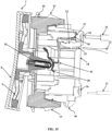
- FIG. 15 illustrates a cross sectional view of the electrical device (2) in which position of external tool slot is changed, accordingly to embodiments as disclosed herein.
- the external tool slot (15) is provided after the wire entry slots (16). The other functionality remains same as described above.
- the proposed the electrical device (2) is advantages to protect the release levers by the switch/socket casing that ensure the long life of the release levers.
- the release levers are not damaged during and post installation of the switch/socket.
- Multiple variety of options can be implemented in the product and solution in this safe and secured assembly and operation of the release lever as described above. Insertion and removal of the wires in the different current applications are easy and secured.
- unexpected disconnection of the wire from the system is eliminated.
- the continuous current supply to systems is maintained with more safe and secured way.
- the proposed the electrical device (2) reduces the installation time and installation cost and less no of parts to create rigid screwless installation system.
Landscapes
- Physics & Mathematics (AREA)
- Electromagnetism (AREA)
- Connections Arranged To Contact A Plurality Of Conductors (AREA)
Abstract
The present invention relates to an electrical device (2) including a rocker assembly (7), a switch assembly (10), and a plunger (11) connected to the rocker assembly (7) and the switch assembly (10). The switch assembly (10) includes a plurality of release levers (12), a switch top case (13), a switch base case (14) connected to the switch top case (13), a terminal cage (17) with a terminal spring (18) connected to the plurality of release levers (12), a common terminal (19) connected to the terminal cage (17), and a moving terminal (20). The switch base case (14) comprises an external tool slot (15) connected to the plurality of release levers (12) and a wire entry slots (16) adapted to receive a stripped wire (21). An external tool (22) is guided to push the release lever (12) and perform a sliding operation over the terminal spring (18).
Description
- The present invention generally relates to the field of switch plate assembly. More specifically, the present invention related to an electrical device having convenient wiring provisions for wall switches, sockets, receptacles and the like.
- Conventional switch or socket plates are generally made with visible screws. However, switch or socket plates having mounting screws visible are not mostly likable, especially switch or socket plates made of metal with decorative surface treatments. Due to the structural limitation of conventional switch or socket plate assemblies are commonly made of plastic to hide mounting screws. Most of the conventional switch plate assemblies are either made of non-metallic materials to hide mounting screws or made of metal with exposed mounting screws on front surfaces.
- Further, conventional installation systems are provided based on different markets and countries and they have different cable sizes. A terminal spring and release lever parts are main components of such conventional screwless installation system. The terminal spring is provided inside a switch or socket assembly which rigidly holds stripped solid or flexible wire and providing anti reversing arrester for the wire. The release lever is provided outside of the switch or socket assembly and accessible by hand to actuate the terminal spring to take out the wire from the switch or socket assembly. The breakage of the release lever happens when unavoidable drop or accident of the switch or socket assembly.
- In the conventional screwless installation systems, when the release lever is pressed by cables which are provided inside installation box after installation of the switch or socket, leads to disconnect the wire from the switch or socket. This disconnection of the wire primes the discontinuity of current to appliances and devices leading to unexpected problem to the users. This kind of problem are generally observed during the installation and consumes more time to properly install the system. Further, the existing release lever design in to be operated by hand, and there exists a chance of misguidance and misalignment in the mechanism and may result in shock hazard.
- With a view therefore to overcome the drawbacks associated with present mechanisms associated with conventional electrical devices and its installation systems for insertion and removal of electrical wires from the wiring terminals of the electrical devices, the inventors felt the need to devise a novel electrical device and installation mechanism for safe and secured installation to the users.
- The principal object of the embodiments herein is to provide electrical device for wall switches, sockets, receptacles and the like. The proposed electrical device ensures rigid wire termination, hassle free installation and eliminates discontinuity of the current to appliances to provide safe and secured installation system to the users. One particular object of the embodiments herein is to provide the electrical device that provides easy insertion of stripped wire with covered and tool operated release lever in the switch or socket assembly to reduced installation time.
- Yet another object of the embodiments herein is to provide release levers in different shape and size eliminates the existing problem and ensure safe and durable operation. The different size of stripped wires with respect to operating current of the switch or socket is entered through the different size of wire entry holes in switch base case of the electrical device.
- Yet another object of the embodiments herein is to perform sliding operation of release levers using an external tool like screw driver. The external tool is guided to head touch the release lever and pushes the release lever to perform the sliding operation over a terminal spring. Further, the sliding operation of the release lever pushes the terminal spring downwards to create a gap between the terminal spring and the terminal cage.
- Accordingly, the present invention provides an electrical device having hassle free provisions for electrical wire installation. The electrical device includes a rocker assembly, a switch assembly connected to the rocker assembly and a plunger connected to the rocker assembly and the switch assembly. The rocker assembly includes an outer rocker, and an inner rocker connected to the outer rocker. The switch assembly includes a plurality of release levers, a switch top case, a switch base case, a switch base case having an external tool slot connected to the plurality of release levers and a wire entry slot adapted to receive a stripped wire, a terminal cage with a terminal spring connected to the plurality of release levers, a common terminal connected to the terminal cage, and a moving terminal connected between the common terminal and the plunger. An external tool is guided to perform a sliding operation over the terminal spring. The sliding operation of the release lever pushes the terminal spring downwards to create a gap between the terminal spring and the terminal cage.
- According to one embodiment of the invention, the stripped wire has contact with the terminal spring. The stripped wire slips on head of the terminal spring and pushes the terminal spring down to enter inside to terminal cage until stopped by a length of the stripped wire.
- In an embodiment, the inner rocker includes flexible arms each of which compress terminal pressure points, a rectangular slot for the terminal cage connected between the flexible arms, a circular slot for screw entry, a lever slot for the release lever, a top wire stopper connected to the rectangular slot, side wire stoppers connected to the top wire stopper, and a wire squeezer punch profile connected to rectangular slot. The wire squeezer punch profile squeezes and holds of the stripped wire.
- According to one embodiment of the invention, the stripped wire has contact with the terminal spring. The stripped wire slips on head of the terminal spring and pushes the terminal spring down to enter inside to terminal cage until stopped by the top wire stopper or side wire stoppers.
- In an embodiment, the plurality of release levers comprises a floating release lever, a hanged release lever, and a pivoted head release lever. The floating release lever includes a wedge to receive the external tool on an inclined face and operating the external tool for releasing the stripped wire, a hammer head observes force exerted by the external tool and operates the terminal spring to release the stripped wire, a CAM Sliding profile member has sliding moment on the terminal spring, and a linear sliding profile member for sliding and retention of sliding axis of the release lever. The release lever slides over the terminal spring using the CAM Sliding profile member and the release lever slides over the terminal spring.
- According to one embodiment of the invention, the hanged lever includes a wedge to receive the external tool on an inclined face and operating the external tool for releasing the stripped wire, a hammer head observes force exerted by the external tool and operates the terminal spring to release the stripped wire, a CAM Sliding profile member has sliding moment on the terminal spring, a hanging hinge retention of the release lever after uninstallation of the stripped wire. The release lever slides over the terminal spring using the CAM Sliding profile member, and a support lever connected to the at least one release lever and the wedge. The hanging hinge is provided between the external tool slot and the common terminal, and the support lever provides support the at least one release lever based on a shape of the release lever, and the support lever comprises one of a straight profile and a zigzag profile.
- In an embodiment, the pivoted head release lever includes a wedge to receive the external tool on an inclined face and operating the external tool for releasing the stripped wire, a hammer head observes force exerted by the external tool and operates the terminal spring to release the stripped wire, a CAM Sliding profile member has sliding moment on the terminal spring. The release lever slides over the terminal spring using the CAM Sliding profile member, a hanging hinge retention of the release lever after uninstallation of the stripped wire, a support lever connected to the release lever and the wedge, and a release lever movement stopper to stop movement of the release lever during the sliding operation. The hanging hinge is provided between the external tool slot and the common terminal. The support lever provides support the release lever based on a shape of the release lever. The support lever comprises one of a straight profile and a zigzag profile.
- According to one embodiment of the invention, the terminal spring is connected to an extended-release lever. The extended-release lever comprises a wire crushing profile. The outer rocker includes terminal holders provided at a centre plate of the outer rocker and a hold and support member provided at top and bottom of the outer rocker. The holder provides the sliding operation to the release lever in the switch assembly.
- In an embodiment, the switch top case includes a release lever guide member that guides the release lever during a release operation of the stripped wire, and a release lever holder connected to the release lever guide. The release lever holder hinged between the switch base case and the common terminal.
- Embodiment of the invention will now be described by way of example only with reference to the accompanying drawings in which:
-
FIGS. 1(a) and2(a) illustrates an assembled view of an electrical device fixed in conventional mounting box provided inside a mounting wall, according to embodiments as disclosed herein; -
FIGS. 1(b) and2(b) illustrates an exploded view of the electrical device fixed in the conventional mounting box provided inside the mounting wall, accordingly to embodiments as disclosed herein; -
FIG. 3 illustrates a cross sectional view of the electrical device, accordingly to embodiments as disclosed herein; -
FIG. 4(a) illustrates a front view of an inner rocker, according to embodiments disclosed herein; -
FIG. 4(b) illustrates a rear view of the inner rocker, according to embodiments disclosed herein; -
FIG. 4(c) illustrates a section view of the inner rocker, according to embodiments disclosed herein; -
FIGS. 5(a)-5(b) illustrates a floating release lever, according to embodiments disclosed herein; -
FIG. 6(a) illustrates a perspective view of a hanged release lever with straight profile, according to embodiments disclosed herein; -
FIG. 6(b) illustrates a side view of the hanged release lever with straight profile, according to embodiments disclosed herein; -
FIG. 6(c) illustrates a perspective view of a hanged release lever with zigzag profile, according to embodiments disclosed herein; -
FIG. 6(d) illustrates a side view of the hanged release lever with zigzag profile, according to embodiments disclosed herein; -
FIGS. 7(a)-7(d) illustrates a pivoted head release lever, according to embodiments disclosed herein; -
FIGS. 8(a)-8(c) illustrates the terminal spring is connected to an extended-release lever, according to embodiments as disclosed herein; -
FIG. 9(a) illustrates a front view of an outer rocker, according to embodiments as disclosed herein; -
FIGS. 9(b)-9(c) illustrates a rear view of the outer rocker, according to embodiments as disclosed herein; -
FIG. 10 illustrates a front perspective the view of switch assembly, according to embodiments as disclosed herein; -
FIG. 11(a) illustrates a front perspective view of the switch assembly, according to embodiments as disclosed herein; -
FIG. 11(b) illustrates a rear perspective view of the switch assembly, according to embodiments as disclosed herein; -
FIG. 12 illustrates a perspective view of switch top case, according to embodiments, as disclosed herein; -
FIG. 13(a) illustrates a section view of the switch assembly with a hanged release lever, according to embodiments as disclosed herein; -
FIG. 13(b) illustrates a section view of the switch assembly with a floating release lever with a floating release lever holder, according to embodiments as disclosed herein; -
FIGS. 14(a)-14(e) illustrates working principal of the proposed electrical device, according to embodiments as disclosed herein; and -
FIG. 15 illustrates a cross sectional view of the electrical device in which position of external tool slot is changed, accordingly to embodiments as disclosed herein. - In the following, numerous specific details are set forth to provide a thorough description of embodiment. Those skilled in the art will recognize and appreciate that, despite of the detailed nature of the exemplary embodiment provided herein; changes and modifications may be applied to said embodiment without limiting or departing from the generally intended scope.
- With reference to
FIGS. 1 through 15 , where similar reference characters denote corresponding features consistently throughout the figures, there are shown preferred implementations. Further, for the sake of simplicity, and without limitation, the same numbers are used throughout the drawings to reference like features and components. The implementations herein will be better understood from the following description with reference to the drawings. - Throughout the disclosure the terms socket and switch are used interchangeably. The term socket can include only socket or socket with switch. Similarly, the term switch can include only switch or switch with socket.
-
FIGS. 1(a) and2(a) illustrates an assembled view of an electrical device (2) fixed in a conventional mounting box (3) provided inside a mounting wall (1), according to embodiments as disclosed herein. The proposed electrical device (2) can be easily mounted inside the mounting conventional box (3) which are provided in the mounting wall (1). In an embodiment, the proposed electrical device (2) can be a switch assembly (10) as shown in the -
FIG. 1(a) or a socket assembly as shown in theFIG. 2(a) .FIGS. 1(b) and2(b) illustrates an exploded view of the electrical device (2) fixed in the conventional mounting box (3) provided inside the mounting wall (1), accordingly to embodiments as disclosed herein. As shown in theFIGS. 1(b) and2(b) , the conventional mounting box (3) adopted to be fixed inside the mounting wall. A fixing frame (4) is connected to the conventional mounting box (3) using mounting screws (5). The proposed electrical device (2) are adopted to be installed inside the conventional mounting box (3). At the end of the installation, a cover frame (6) is attached on surface of the mounting wall (1). The cover frame (6) is fixed on the fixing frame (4) to get better look. -
FIG. 3 illustrates a cross sectional view of the electrical device (2), accordingly to embodiments as disclosed herein. The electrical device (2) includes a rocker assembly (7), a switch assembly (10) (or referred as socket assembly (10)) connected to the rocker assembly (7), and a plunger (11) connected to the rocker assembly (7) and the switch assembly (10). The rocker assembly (7) comprising an outer rocker (8), and an inner rocker (9) connected to the outer rocker (8). The switch assembly (10) includes one or more release levers (12), a switch top case (13), a switch base case (14), a terminal cage (17), a common terminal (19), and a moving terminal (20). The switch base case (14) is connected to the switch top case (13). The switch base case (14) includes an external tool slot (15) connected to the one or more release levers (12) and wire entry slots (16) adapted to receive a stripped wire (21). The terminal cage (17) is provided with a terminal spring (18) connected to the plurality of release levers (12). The common terminal (19) is connected to the terminal cage (17). The moving terminal (20) is connected between the common terminal (19) and the plunger (11). An external tool (22) is guided to push the at least one release lever (12) of the plurality of release levers (12) and perform a sliding operation over the terminal spring (18). - In an embodiment, the wire entry slots (16) are provided in both screw and screwless assembly to guide and have wire the switch assembly (10) in distinct size based on the requirement of the operating current rating of the switch and socket. In an embodiment, the stripped wire (21) has contact with the terminal spring (18) that slips on head of the terminal spring (18) and pushes the terminal spring (18) down to enter inside the terminal cage (17) until stopped by a length of the stripped wire (21). In an embodiment, the sliding operation of the at least one release lever (12) pushes the terminal spring (18) downwards to create a gap between the terminal spring (18) and the terminal cage (17). The proposed disclosure provides the release levers (12), the terminal spring (18) and the contact terminals such as the common terminal (19) and the moving terminal (20) based solution to solve the existing problem and bringing better solution to the screwless installation.
- The proposed solution is applicable and adaptable to all low voltage lighting applications. In an embodiment, the release lever (12) has designed in distinctive style like a floating release lever (12), a hanged release lever (12), a hanged release lever (12), and a pivoted head release lever. All the variants of designs have kept in closed enclosure. These release levers (12) are assembled with switch/socket top and switch/socket base casing. The external tool slot (15) provided in all the switch/socket assembly in different direction/location to operate the release lever (12) by the external tool (22) like a screwdriver. The slots provided with respect to the different wire entries like top, back, front, or bottom and right or left side wire entries likewise the external tool (22) access and operation is one in the top, back, front, or bottom and the right or left side. Modification on the hinge of the release lever (12) is to make better interface with the parts in the switch or socket assembly (10).
- The release lever (12) is designed with wedge (31) to slide in the switch assembly (10) when operated with the external tool (22) and hammer head to press the terminal spring (18). The terminal spring (18) is designed with different profile to provide spring back action, wire holding with bended head to be pressed by head of the release lever (12) during the sliding operation. The contact terminals (19 and 20) are designed with different cross section and style to accommodate the release lever (12) and the terminal spring (18). In the switch assembly (10), the contact terminals (19 and 20) are compatible for both screw and screwless wire terminations. Features in the new contact terminals contact terminals (19 and 20) are designed with consideration of the conductive cross section of the terminals with current ratings. The same contact terminals (19 and 20) can used for different current ratings with coatings and different conductive material if required.
- In the proposed disclosure, new release levers (12) are designed, the terminal spring (18) and the contact terminals (19 and 20) with consideration of the functional requirements. Through the proposed disclosure, the existing problem has cleared studied and solved with the proposed solutions. The proposed disclosure ensures safety in assembly, the electrical device (2), and installation. The continuous current supply has delivered to the switch/socket and other functions. The installation time reduced and led the cost benefit to the end customer in terms of less installation time and replacing the damaged parts.
-
FIG. 4(a) illustrates a front view of the inner rocker (9), according to embodiments disclosed herein.FIG. 4(b) illustrates a rear view of the inner rocker (9), according to embodiments disclosed herein.FIG. 4(c) illustrates a section view of the inner rocker (9), according to embodiments disclosed herein. The inner rocker (9) includes flexible arms (23), rectangular slot (24), circular slot (25), lever slot (26), top wire stopper (27), side wire stoppers (28), wire squeezer punch profile (29) and terminal pressure points (30). - The flexible arms (23) each of which compress terminal pressure points. The rectangular slot (24) for the terminal cage (17) is connected between the flexible arms (23). The common contact terminal has provisions to the screwless terminal holding in the switch assembly (10). The circular slot (25) is used for screw entry. The common contact terminal has provisions to the screw terminal holding in the switch assembly (10). The lever slot (26) is for the at least one release lever. The lever slot (26) is to have the main member of the screwless mechanism called release lever which is used to release the wire during uninstallation or repair of the switch assembly (10).
- The top wire stopper (27) is connected to the rectangular slot (24) and is used to stop excessive of the stripped wire (21) in the switch assembly (10). The side wire stoppers (28) are connected to the top wire stopper (27). This feature stops and secures the switch assembly (10) from unavoidable touch between the stripped wire (21) and plastic parts in the switch assembly (10). In an embodiment, the stripped wire (21) has contact with the terminal spring (18). The stripped wire (21) slips on head of the terminal spring (18) and pushes the terminal spring (18) down to enter inside to terminal cage (17) until stopped by the top wire stopper (27) or the side wire stoppers (28). The wire squeezer punch profile (29) is connected to rectangular slot (24). The wire squeezer punch profile (29) squeezes and holds of the stripped wire (21). This punch profile is used to squeeze and ensure robust holding of the stripped wire (21) in the screw and screwless installation. The proposed punch profile creates the different shape and curve in the installed stripped wire (21) to make more robust holding in the wire termination.
- The proposed disclosure includes with wiring devices switches, socket outlet and any connected devices which intake power supply through wide varieties of flexible and rigid cables. In the switches and socket outlets, terminals which holds plug pins or transmit or make and break the contacts are provided. In the proposed invention, flexible feature which holds plug pin firmly and exerts specified force requirement on the plug pin to withstand no of cycle of operation including screwless terminations are provided.
FIGS. 5(a)-5(b) illustrates the floating release lever (12), according to embodiments disclosed herein. The floating release lever includes a wedge (31), a hammer head (32), a CAM sliding profile member (33), and a linear sliding profile member (34). - The wedge (31) receives the external tool (22) on an inclined face and operating the external tool (22) for releasing the stripped wire (21). The wedge (31) acts as cam profile in the floating release lever. This receives the external tool (22) on its inclined face and operating the screwless terminal while releasing the stripped wire (21). To operate the release levers (12) in the safe with proper guidance, the external tool slot (15) is used in the switch base case (14). The external tool slot (15) directs the external tool (22) to the wedge (31) of the release lever (12) and proving reactive force to the external tool (22) in the sliding operation.
- The hammer head (32) is connected to the wedge (31). The hammer head (32) observes force exerted by the external tool (22) and operates the terminal spring (18) to release the stripped wire (21). The hammer head (32) is a strongest portion in the part. This part observes operation force exerted by the external tool (22) and operates the terminal spring (18) to release the stripped wire (21).
- The CAM sliding profile member (33) is connected to the wedge (31) and the hammer head (32). The CAM sliding profile member (33) has sliding moment on the terminal spring (18). The release lever (12) slides over the terminal spring (18) using the CAM sliding profile member (33). In an embodiment, the floating release lever exactly has cam shaped profile feature which has sliding moment on the terminal spring (18) and supports for the smooth operation during the wire uninstallation in the switch assembly (10).
- The linear sliding profile member (34) is provided for sliding and retention of sliding axis of the at least one release lever (12), wherein the release lever (12) slides over the terminal spring (18). When the release lever (12) slides over head of the terminal spring (18) like cam and follow the linear sliding profile to ensure the sliding and retention of sliding axis of the release lever (12). The linear sliding profile is to be supported on the flat face of the base casing of the switch assembly (10).
-
FIG. 6(a) illustrates a perspective view of a hanged release lever with straight profile, according to embodiments disclosed herein.FIG. 6(b) illustrates a side view of the hanged release lever with straight profile, according to embodiments disclosed herein. The hanged release lever includes a wedge (31), a hammer head (32), a CAM sliding profile member (33), a hanging hinge (35) and a support lever (36). - The wedge (31), as shown in
FIGS. 6(b) and6(d) , receives the external tool (22) on an inclined face and operating the external tool (22) for releasing the stripped wire (21). The wedge (31) acts as cam profile in the hanged release lever. This receives the external tool (22) on its inclined face and operating the screwless terminal while releasing the stripped wire (21). The external tool slot (15) directs the external tool (22) to the wedge (31) of the release lever (12) and proving reactive force to the external tool (22) in the sliding operation. - It is also seen that the hammer head (32) is connected to the wedge (31). The hammer head (32) observes force exerted by the external tool (22) and operates the terminal spring (18) to release the stripped wire (21). The hammer head (32) is a strongest portion in the part. This part observes operation force exerted by the external tool (22) and operates the terminal spring (18) to release the stripped wire (21).
- It can be also seen in
FIGS. 6(a)-6(d) , the CAM sliding profile member (33) is connected to the wedge (31) and the hammer head (32). The CAM sliding profile member (33) has sliding moment on the terminal spring (18). The release lever (12) slides over the terminal spring (18) using the CAM sliding profile member (33). In an embodiment, the hanged release lever exactly has cam shaped profile feature which has sliding moment on the terminal spring (18) and supports for the smooth operation during the wire uninstallation in the switch assembly (10). The hanging hinge (35) is connected to the wedge (31). The hanging hinge (35) is provided for retention of the release lever (12) after uninstallation of the stripped wire (21). The hanging hinge (35) is provided between the external tool slot (15) and the common terminal (19). This feature hanged and acting as hinge to ensure the retention of the release lever (12) after the wire uninstallation in the switch assembly (10). The hanging hinge (35) is held between the switch top case (13) and the contact terminals (19 and 20). - The support lever (36) is connected to the hanging hinge (35) and the wedge (31). The support lever (36) provides support the at least one release lever (12) based on a shape of the at least one release lever (12). In an embodiment, the support lever (36) has a straight profile as shown in the
FIG. 6(b) . In an embodiment, the support lever (36) has a zigzag profile as shown in theFIGS. 6(c)-6(d). FIG. 6(c) illustrate a perspective view of a hanged release lever with zigzag profile, according to embodiments disclosed herein.FIG. 6(d) illustrates a side view of the hanged release lever with zigzag profile, according to embodiments disclosed herein. The support lever (36) brings the flexibility in the sliding operation of the release lever (12) and supporting the retention of the release lever (12). This feature may be the straight profile and other shape based on the requirement of flexibility to the sliding operation of the release lever (12). -
FIGS. 7(a)-7(d) illustrate a pivoted head release lever, according to embodiments disclosed herein. The pivoted head release lever includes a wedge (31), a hammer head (32), a CAM sliding profile member (33), a hanging hinge (35) a support lever (36), and a release lever movement stopper (37). The wedge (31), as indicated inFIG. 7(c) receives the external tool (22) on an inclined face and operating the external tool (22) for releasing the stripped wire (21). The wedge (31) acts as cam profile in the pivoted head release lever. This receives the external tool (22) on its inclined face and operating the screwless terminal while releasing the stripped wire (21). The external tool slot (15) directs the external tool (22) to the wedge (31) of the release lever (12) and proving reactive force to the external tool (22) in the sliding operation. - The hammer head (32), as shown in
FIGS. 7(a) and 7(c) is connected to the wedge (31). The hammer head (32) observes force exerted by the external tool (22) and operates the terminal spring (18) to release the stripped wire (21). The hammer head (32) is a strongest portion in the part. This part observes operation force exerted by the external tool (22) and operates the terminal spring (18) to release the stripped wire (21). The CAM sliding profile member (33) is connected to the wedge (31) and the hammer head (32). The CAM sliding profile member (33) has sliding moment on the terminal spring (18). The release lever (12) slides over the terminal spring (18) using the CAM sliding profile member (33). In an embodiment, the pivoted head release lever exactly has cam shaped profile feature which has sliding moment on the terminal spring (18) and supports for the smooth operation during the wire uninstallation in the switch assembly (10). - The hanging hinge (35), as depicted in
FIGS. 7(b) and 7(d) , is connected to the wedge (31). The hanging hinge (35) is provided for retention of the release lever (12) after uninstallation of the stripped wire (21). The hanging hinge (35) is provided between the external tool slot (15) and the common terminal (19). This feature hanged and acting as hinge to ensure the retention of the release lever (12) after the wire uninstallation in the switch assembly (10). The hanging hinge (35) is held between the switch top case (13) and the contact terminals (19 and 20). - The support lever (36) is connected to the hanging hinge (35) and the wedge (31). The support lever (36) provides support the at least one release lever (12) based on a shape of the at least one release lever (12). In an embodiment, the support lever (36) has a straight profile or any other shape based on the requirement of flexibility to operate the release lever (12). The support lever (36) brings the flexibility in the sliding operation of the release lever (12) and supporting the retention of the release lever (12). This feature may be the straight profile and other shape based on the requirement of flexibility to the sliding operation of the release lever (12).
- The release lever movement stopper (37) is connected to the hanging hinge (35). The release lever movement stopper (37) stops movement of the at least one release lever (12) during the sliding operation to make robustness in the function during the wire insertion. If the release lever movement stopper (37) is not provided the release lever (12) move in opposite direction downside to wire entry and there may be loss or collapse in the connection.
-
FIGS. 8(a)-8(c) illustrates the terminal spring (18) is connected to an extended-release lever (38), according to embodiments as disclosed herein. The terminal spring (18) is connected to the extended-release lever (38) having a wire crushing profile (39) and a release lever sliding profile (40). The extended-release lever (38) reduces plastic part. - In an embodiment, the terminal spring (18) includes a locking profile (41) and push feature (42) to push wire upside to make robust fixation. The extended-release lever (38) is the extended portion of the terminal spring (18), and this feature reduces the one more part in the switch assembly (10) to release the stripped wire (21). The extended-release lever (38) can be accessed directly through the external tool slot (15) in the switch base case (14) to release the stripped wire (21).
-
FIG. 9(a) illustrates a front view of the outer rocker (8), according to embodiments as disclosed herein. The outer rocker (8) includes a socket or switch centre plate (43).FIGS. 9(b)-9(c) illustrates a rear view of the outer rocker (8), according to embodiments as disclosed herein. - The outer rocker (8) comprises terminal holders (44) and a hold and support member (45). The terminal holders (44) are provided at the centre plate (43) of the outer rocker (8). The terminal holders (44) provide the sliding operation to the at least one release lever (12) in the switch assembly (10). The hold and support member (45) are provided at top and bottom of the outer rocker (8). In an embodiment, the hold and support member (45) are provided for the hinged lever. The floating and hanging release levers supported and guided directly in the contact terminal slot. In order to provide better support from z axis the supports brought for the top and base casing of the socket assembly. This feature supports and provides the sliding operation to the release lever (12) in the screwless terminal assembly.
-
FIG. 10 illustrates a front perspective view of the switch base case (14), according to embodiments as disclosed herein. The switch base case (14) includes the external tool slot (15) connected to the one or more release levers (12) and the wire entry slots (16) adapted to receive the stripped wire (21). To operate the release levers (12) in the safe with proper guidance these slots used in the switch base case (14). The external tool slot (15) slots direct the screwdriver to the wedge portion of the release lever (12) and proving reactive force to the screwdriver in the sliding operation. Further, the wire entry slots (16) are there in both screw and screwless assembly to guide and have wire the switch base case (14) in distinct size based on the requirement of the operating current rating of the switch and socket. -
FIG. 11(a) illustrates a front perspective view of the switch base case (14), according to embodiments as disclosed herein. The switch base case (14) includes the external tool slot (15) connected to the one or more release levers (12) and the wire entry slots (16) adapted to receive the stripped wire (21).FIG. 11(b) illustrates a rear perspective view of the switch base case (14), according to embodiments as disclosed herein. The switch base case (14) includes the terminal holders (44). -
FIG. 12 illustrates a perspective view of the switch top case (13), according to embodiments as disclosed herein. The switch top case (13) includes release lever holders (46) that guide the at least one release lever (12) during a release operation of the stripped wire (21), wherein the release lever holders (46) are hinged between the switch base case (14) and the common terminal (19).FIGS. 13(a) illustrates a section view of the switch base case (14) with a hanged release lever (47), according to embodiments as disclosed herein. The switch base case (14) includes casing (48, 49).FIG. 13(b) illustrates a section view of the switch base case (14) with a floating release lever (50) with a floating release lever holder (51), according to embodiments as disclosed herein. -
FIGS. 14(a)-14(e) illustrates working principal of the proposed electrical device (2), according to embodiments as disclosed herein. An electrical device (2) is provided as illustrated in theFIG. 14(a) . The stripped wire (21) is inserted in the switch base case (14) through the wire entry slots (16) as shows in theFIG. 14(b) . TheFIG. 14(c) illustrates the electrical device (2) with the stripped wire inserted condition. Upward push (52) to make robust wire fixation by squeezing the stripped wire (21). An interference (53) between the stripped wire (21) and the terminal spring (18) is provided based on the upward push (52). TheFIG. 14(d) illustrates pushing of the external tool (22) in the external tool slot (15) to actuate the release lever (12). The release lever (12) is actuated by the external tool (22) and the release lever (12) is compress the terminal spring (18) and thus the interference (53) is removed between the stripped wire (21) and the terminal spring (18). TheFIG. 14(e) illustrates the stripped wire (21) is easily removed from the switch base case (14). Original positions (55) of the release lever (12), the terminal spring (18) are retained after the stripped wire (21) is released. The stripped wire (21) has reduced or bulged diameter with squeezed mark (54) by the terminal spring (18). - Unlike to conventional system, by introducing the different release levers in different shape and size eliminates the existing problem and ensure the safe and durable operation. The different size of the stripped wires (21) with respect to the operating current of the switch/socket is entered through the different size of the stripped wires (21) entry the wire entry slots (16) in the switch base case (14) of the switch or socket. Once the stripped wire (21) has contact with the terminal spring (18), the stripped wire (21) slips on head of the terminal spring (18) and pushes the terminal spring (18) down to enter inside to contact terminal/terminal cage (17) until stopped by the wire stopper or stripped length of the stripped wire (21). The sharp edge of the terminal spring (18) retracts to reach its original position and creates the pressure to crush the stripped wires (21) between the terminal spring (18) and screwless terminal cage (17). The installer or end user cannot remove the wire for the screwless terminal since it is strongly held between the terminal spring (18) and the terminal cage (17). To remove the stripped wires (21) without damage to the stripped wires (21) and the release levers (12) are operated by the external tool (22). Further, installer/end user is to use prescribed size of the external tool (22) such as screwdriver and insert into the external tool slot (15) in the switch base case (14) of the switch or socket. Properly guided screwdriver head touches head of the release lever (12) and pushes the release lever (12) further because of the force applied by the installer/end user.
- The release lever (12) tries to have sliding over the terminal spring (18) because of the cam and follower profile in both parts and the release lever (12) supported and guided in other axis and turning of the screwdriver by the installer/end user. The sliding operation of the release lever (12) pushes the terminal spring (18) downwards to create more gap between the terminal spring (18) and the terminal cage (17). The excess of the terminal cage (17) between them creates easy removal of the stripped wire (21) from the screwless terminal since the spring pressure removed by the release lever (12). Furthermore, the screwdriver is removed from the external tool slot (15) once the stripped wire (21) is released from the switch assembly (10).
FIG. 15 illustrates a cross sectional view of the electrical device (2) in which position of external tool slot is changed, accordingly to embodiments as disclosed herein. In an embodiment, the external tool slot (15) is provided after the wire entry slots (16). The other functionality remains same as described above. - Unlike the conventional socket or switch installation systems, the proposed the electrical device (2) is advantages to protect the release levers by the switch/socket casing that ensure the long life of the release levers. The release levers are not damaged during and post installation of the switch/socket. Also, there is no contact between the wire inside the installation box and the release lever. Multiple variety of options can be implemented in the product and solution in this safe and secured assembly and operation of the release lever as described above. Insertion and removal of the wires in the different current applications are easy and secured. In the proposed the electrical device (2), unexpected disconnection of the wire from the system is eliminated. The continuous current supply to systems is maintained with more safe and secured way. The proposed the electrical device (2) reduces the installation time and installation cost and less no of parts to create rigid screwless installation system.
- As already mentioned, the foregoing description is illustrative of the invention and not limitative to its scope, because it will be apparent to persons skilled in the art to devise other alternative embodiments without departing from the broad ambit of the disclosures made herein.
Part-List: Sr. No. Description Sr. No. Description 1 mounting wall 25 circular slot 2 electrical device 26 lever slot 3 conventional mounting box 27 top wire stopper 4 fixing frame 28 side wire stoppers 5 mounting screws 29 wire squeezer punch profile 6 cover frame 30 terminal pressure points 7 rocker assembly 31 wedge 8 outer rocker 32 hammer head 9 inner rocker 33 CAM sliding profile member 10 switch assembly 34 linear sliding profile member 11 plunger 35 hanging hinge 12 release levers 36 support lever 13 switch top case 37 release lever movement stopper 14 switch base case 38 extended- release lever 15 external tool slot 39 Wire crushing profile 16 wire entry slots 40 release lever sliding profile 17 terminal cage 41 locking profile 18 terminal spring 42 push feature 19 common terminal 43 centre plate 20 moving terminal 44 terminal holders 21 stripped wire 45 hold and support member 22 external tool 46 release lever holders 23 flexible arms 47 hanged release lever 24 rectangular slot 48, 49 casing 50 floating release lever 51 floating release lever holder 52 Upward push 53 interference 54 squeezed mark 55 position
Claims (12)
- An electrical device (2) comprising:- a rocker assembly (7) comprising an outer rocker (8), and an inner rocker (9) connected to the outer rocker (8);- a switch assembly (10) connected to the rocker assembly (7); and- a plunger (11) connected to the rocker assembly (7) and the switch assembly (10), wherein the switch assembly (10) comprising:- plurality of release levers (12),- a switch top case (13),- a switch base case (14) connected to the switch top case (13), wherein the switch base case (14) comprises an external tool slot (15) connected to the plurality of release levers (12) and a wire entry slots (16) adapted to receive a stripped wire (21),- a terminal cage (17) with a terminal spring (18) connected to the plurality of release levers (12),- a common terminal (19) connected to the terminal cage (17), and- a moving terminal (20) connected between the common terminal (19) and the plunger (11),wherein an external tool (22) is guided to push the at least one release lever (12) of the plurality of release levers (12) and perform a sliding operation over the terminal spring (18).
- The electrical device (2) as claimed in claim 1, wherein the stripped wire (21) has contact with the terminal spring (18) that slips on head of the terminal spring (18) and pushes the terminal spring (18) down to enter inside the terminal cage (17) until stopped by a length of the stripped wire (21).
- The electrical device (2) as claimed in claim 1 or 2, wherein the sliding operation of the at least one release lever (12) pushes the terminal spring (18) downwards to create a gap between the terminal spring (18) and the terminal cage (17).
- The electrical device (2) as claimed in any one of the preceding claims, wherein the inner rocker (9) comprises:- flexible arms (23) each of which compress terminal pressure points;- a rectangular slot (24) for the terminal cage (17) connected between the flexible arms (23);- a circular slot (25) for screw entry;- a lever slot (26) for the at least one release lever (12);- a top wire stopper (27) connected to the rectangular slot (24);- side wire stoppers (28) connected to the top wire stopper (27); and- a wire squeezer punch profile (29) connected to the rectangular slot (24), wherein the wire squeezer punch profile (29) squeezes and holds of the stripped wire (21).
- The electrical device (2) as claimed in claim 4, wherein the stripped wire (21) has contact with the terminal spring (18), and wherein the stripped wire (21) slips on head of the terminal spring (18) and pushes the terminal spring (18) down to enter inside to terminal cage (17) until stopped by the top wire stopper (27) or the side wire stoppers (28).
- The electrical device (2) as claimed in any one of the preceding claims, wherein the plurality of release levers (12) comprises a floating release lever, a hanged release lever, and a pivoted head release lever.
- The electrical device (2) as claimed in claim 6, wherein the floating release lever comprises:- a wedge (31) to receive the external tool (22) on an inclined face and operating the external tool (22) for releasing the stripped wire (21), wherein the external tool slot (15) directs the external tool (22) to the wedge (31) of the release lever (12) and proving reactive force to the external tool (22) in the sliding operation;- a hammer head (32) is connected to the wedge (31), wherein the hammer head (32) observes force exerted by the external tool (22) and operates the terminal spring (18) to release the stripped wire (21);- a CAM sliding profile member (33) connected to the wedge (31) and the hammer head (32), wherein the CAM sliding profile member (33) has sliding moment on the terminal spring (18), wherein the at least one release lever (12) slides over the terminal spring (18) slides using the CAM sliding profile member (33); and- a linear sliding profile member (34) for sliding and retention of sliding axis of the at least one release lever (12), wherein the at least one release lever (12) slides over the terminal spring (18).
- The electrical device (2) as claimed in claim 6 or 7, wherein the hanged release lever comprises:- a wedge (31) to receive the external tool (22) on an inclined face and operating the external tool (22) for releasing the stripped wire (21), wherein the external tool slot (15) directs the external tool (22) to the wedge (31) of the release lever (12) and proving reactive force to the external tool (22) in the sliding operation;- a hammer head (32) connected to the wedge (31), wherein the hammer head (32) observes force exerted by the external tool (22) and operates the terminal spring (18) to release the stripped wire (21);- a CAM sliding profile member (33) connected to the hammer head (32) and the wedge (31), wherein the CAM sliding profile member (33) has sliding moment on the terminal spring (18), wherein the at least one release lever (12) slides over the terminal spring (18) slides using the CAM sliding profile member (33);- a hanging hinge (35) connected to the wedge (31), wherein the handing hinge is provided for retention of the at least one release lever (12) after uninstallation of the stripped wire (21), wherein the hanging hinge (35) is provided between the external tool slot (15) and the common terminal (19); and- a support lever (36) connected to the hanging hinge (35) and the wedge (31), wherein the support lever (36) provides support the at least one release lever (12) based on a shape of the at least one release lever (12), and wherein the support lever (36) comprises one of a straight profile and a zigzag profile.
- The electrical device (2) as claimed in any one of the preceding claims 6 to 8, wherein the pivoted head release lever comprises:- a wedge (31) to receive the external tool (22) on an inclined face and operating the external tool (22) for releasing the stripped wire (21), wherein the external tool slot (15) directs the external tool (22) to the wedge (31) of the release lever (12) and proving reactive force to the external tool (22) in the sliding operation;- a hammer head (32) observes force exerted by the external tool (22) and operates the terminal spring (18) to release the stripped wire (21);- a CAM sliding profile member (33) has sliding moment on the terminal spring (18), wherein the at least one release lever (12) slides over the terminal spring (18) slides using the CAM sliding profile member (33);- a hanging hinge (35) retention of the at least one release lever (12) after uninstallation of the stripped wire (21), wherein the hanging hinge (35) is provided between the external tool slot (15) and the common terminal (19);- a support lever (36) connected to the hanging hinge (35) and the wedge (31), wherein the support lever (36) provides support the at least one release lever (12) based on a shape of the at least one release lever (12); and- a release lever movement stopper (37) connected to the hanging hinge (35), wherein the release lever movement stopper (37) stops movement of the at least one release lever (12) during the sliding operation.
- The electrical device (2) as claimed in claim 1, wherein the terminal spring (18) is connected to an extended-release lever (12), wherein the extended-release lever (38) comprises a wire crushing profile (39) and a release lever sliding profile (40).
- The electrical device (2) as claimed in any one of the preceding claims, wherein the outer rocker (8) comprises:
terminal holders (44) provided at a center plate (43) of the outer rocker (8), wherein the terminal holders (44) provide the sliding operation to the at least one release lever (12) in the switch assembly (10); and hold and support members (44) provided at top and bottom of the outer rocker (8). - The electrical device (2) as claimed in any one of the preceding claims, wherein the switch top case (13) comprises release lever holders (46) that guide the at least one release lever (12) during a release operation of the stripped wire (21), wherein the release lever holders (46) are hinged between the switch base case (14) and the common terminal (19).
Applications Claiming Priority (1)
| Application Number | Priority Date | Filing Date | Title |
|---|---|---|---|
| IN202331073901 | 2023-10-30 |
Publications (1)
| Publication Number | Publication Date |
|---|---|
| EP4550581A1 true EP4550581A1 (en) | 2025-05-07 |
Family
ID=92926213
Family Applications (1)
| Application Number | Title | Priority Date | Filing Date |
|---|---|---|---|
| EP24202840.5A Pending EP4550581A1 (en) | 2023-10-30 | 2024-09-26 | Electrical device having wire installation mechanism |
Country Status (1)
| Country | Link |
|---|---|
| EP (1) | EP4550581A1 (en) |
Citations (1)
| Publication number | Priority date | Publication date | Assignee | Title |
|---|---|---|---|---|
| EP2423937A2 (en) * | 2010-08-26 | 2012-02-29 | Schneider Electric Espana, S.A. | Switch for electrical installations |
-
2024
- 2024-09-26 EP EP24202840.5A patent/EP4550581A1/en active Pending
Patent Citations (1)
| Publication number | Priority date | Publication date | Assignee | Title |
|---|---|---|---|---|
| EP2423937A2 (en) * | 2010-08-26 | 2012-02-29 | Schneider Electric Espana, S.A. | Switch for electrical installations |
Similar Documents
| Publication | Publication Date | Title |
|---|---|---|
| CN101682128B (en) | Installation switchgear having a spring-loaded terminal arrangement | |
| EP3707783B1 (en) | Push-on socket | |
| EP0648001B1 (en) | Access flooring module | |
| US6494728B1 (en) | Safety electrical connection system | |
| US6368129B1 (en) | Electrical connector with outer and inner sleeves | |
| EP2747214B1 (en) | A releasing mechanism for disengagement of patch cord and individual port member | |
| US20020182938A1 (en) | DSX jack LED activation & grounding system | |
| CN101141030B (en) | Plug holder for at least one plug | |
| EP2240983B1 (en) | Locking electrical receptacle | |
| CN217484811U (en) | Server | |
| EP1531523B1 (en) | Lead connector for circuit board | |
| EP0812031A2 (en) | Device for the guided movement of connecting terminal screws for electrical apparatus | |
| EP1865577B1 (en) | Screwless, two-way binding post terminal | |
| CN213124949U (en) | Binding post connector | |
| CN209786209U (en) | Split type conductive clamping mechanism and wiring terminal with same | |
| CN113300168A (en) | Locking module and socket | |
| CN212277527U (en) | Socket convenient to plug is fixed | |
| KR20180110465A (en) | one touch typed concent | |
| CN220527243U (en) | Terminal assembly and high-voltage connector | |
| CN107104319B (en) | A kind of push type inserted sheet socket | |
| CN111816518B (en) | Binding post and circuit breaker | |
| CN214706289U (en) | Wiring terminal | |
| EP3059809B1 (en) | A plug comprising a pullout mechanism | |
| CN221282427U (en) | Socket structure, plug structure and socket assembly | |
| CN110931991A (en) | Split type conductive clamping mechanism and wiring terminal with same |
Legal Events
| Date | Code | Title | Description |
|---|---|---|---|
| PUAI | Public reference made under article 153(3) epc to a published international application that has entered the european phase |
Free format text: ORIGINAL CODE: 0009012 |
|
| STAA | Information on the status of an ep patent application or granted ep patent |
Free format text: STATUS: REQUEST FOR EXAMINATION WAS MADE |
|
| 17P | Request for examination filed |
Effective date: 20240926 |
|
| AK | Designated contracting states |
Kind code of ref document: A1 Designated state(s): AL AT BE BG CH CY CZ DE DK EE ES FI FR GB GR HR HU IE IS IT LI LT LU LV MC ME MK MT NL NO PL PT RO RS SE SI SK SM TR |