EP4550550A1 - Battery pack - Google Patents
Battery pack Download PDFInfo
- Publication number
- EP4550550A1 EP4550550A1 EP23830956.1A EP23830956A EP4550550A1 EP 4550550 A1 EP4550550 A1 EP 4550550A1 EP 23830956 A EP23830956 A EP 23830956A EP 4550550 A1 EP4550550 A1 EP 4550550A1
- Authority
- EP
- European Patent Office
- Prior art keywords
- terminal
- holder
- battery pack
- recess
- storage space
- Prior art date
- Legal status (The legal status is an assumption and is not a legal conclusion. Google has not performed a legal analysis and makes no representation as to the accuracy of the status listed.)
- Pending
Links
Images




Classifications
-
- H—ELECTRICITY
- H01—ELECTRIC ELEMENTS
- H01M—PROCESSES OR MEANS, e.g. BATTERIES, FOR THE DIRECT CONVERSION OF CHEMICAL ENERGY INTO ELECTRICAL ENERGY
- H01M50/00—Constructional details or processes of manufacture of the non-active parts of electrochemical cells other than fuel cells, e.g. hybrid cells
- H01M50/20—Mountings; Secondary casings or frames; Racks, modules or packs; Suspension devices; Shock absorbers; Transport or carrying devices; Holders
- H01M50/296—Mountings; Secondary casings or frames; Racks, modules or packs; Suspension devices; Shock absorbers; Transport or carrying devices; Holders characterised by terminals of battery packs
-
- H—ELECTRICITY
- H01—ELECTRIC ELEMENTS
- H01M—PROCESSES OR MEANS, e.g. BATTERIES, FOR THE DIRECT CONVERSION OF CHEMICAL ENERGY INTO ELECTRICAL ENERGY
- H01M50/00—Constructional details or processes of manufacture of the non-active parts of electrochemical cells other than fuel cells, e.g. hybrid cells
- H01M50/20—Mountings; Secondary casings or frames; Racks, modules or packs; Suspension devices; Shock absorbers; Transport or carrying devices; Holders
- H01M50/204—Racks, modules or packs for multiple batteries or multiple cells
- H01M50/207—Racks, modules or packs for multiple batteries or multiple cells characterised by their shape
-
- H—ELECTRICITY
- H01—ELECTRIC ELEMENTS
- H01M—PROCESSES OR MEANS, e.g. BATTERIES, FOR THE DIRECT CONVERSION OF CHEMICAL ENERGY INTO ELECTRICAL ENERGY
- H01M50/00—Constructional details or processes of manufacture of the non-active parts of electrochemical cells other than fuel cells, e.g. hybrid cells
- H01M50/20—Mountings; Secondary casings or frames; Racks, modules or packs; Suspension devices; Shock absorbers; Transport or carrying devices; Holders
- H01M50/218—Mountings; Secondary casings or frames; Racks, modules or packs; Suspension devices; Shock absorbers; Transport or carrying devices; Holders characterised by the material
- H01M50/22—Mountings; Secondary casings or frames; Racks, modules or packs; Suspension devices; Shock absorbers; Transport or carrying devices; Holders characterised by the material of the casings or racks
- H01M50/231—Mountings; Secondary casings or frames; Racks, modules or packs; Suspension devices; Shock absorbers; Transport or carrying devices; Holders characterised by the material of the casings or racks having a layered structure
-
- H—ELECTRICITY
- H01—ELECTRIC ELEMENTS
- H01M—PROCESSES OR MEANS, e.g. BATTERIES, FOR THE DIRECT CONVERSION OF CHEMICAL ENERGY INTO ELECTRICAL ENERGY
- H01M50/00—Constructional details or processes of manufacture of the non-active parts of electrochemical cells other than fuel cells, e.g. hybrid cells
- H01M50/20—Mountings; Secondary casings or frames; Racks, modules or packs; Suspension devices; Shock absorbers; Transport or carrying devices; Holders
- H01M50/298—Mountings; Secondary casings or frames; Racks, modules or packs; Suspension devices; Shock absorbers; Transport or carrying devices; Holders characterised by the wiring of battery packs
-
- H—ELECTRICITY
- H01—ELECTRIC ELEMENTS
- H01M—PROCESSES OR MEANS, e.g. BATTERIES, FOR THE DIRECT CONVERSION OF CHEMICAL ENERGY INTO ELECTRICAL ENERGY
- H01M50/00—Constructional details or processes of manufacture of the non-active parts of electrochemical cells other than fuel cells, e.g. hybrid cells
- H01M50/50—Current conducting connections for cells or batteries
- H01M50/572—Means for preventing undesired use or discharge
- H01M50/584—Means for preventing undesired use or discharge for preventing incorrect connections inside or outside the batteries
- H01M50/588—Means for preventing undesired use or discharge for preventing incorrect connections inside or outside the batteries outside the batteries, e.g. incorrect connections of terminals or busbars
-
- H—ELECTRICITY
- H01—ELECTRIC ELEMENTS
- H01M—PROCESSES OR MEANS, e.g. BATTERIES, FOR THE DIRECT CONVERSION OF CHEMICAL ENERGY INTO ELECTRICAL ENERGY
- H01M50/00—Constructional details or processes of manufacture of the non-active parts of electrochemical cells other than fuel cells, e.g. hybrid cells
- H01M50/50—Current conducting connections for cells or batteries
- H01M50/572—Means for preventing undesired use or discharge
- H01M50/584—Means for preventing undesired use or discharge for preventing incorrect connections inside or outside the batteries
- H01M50/59—Means for preventing undesired use or discharge for preventing incorrect connections inside or outside the batteries characterised by the protection means
- H01M50/593—Spacers; Insulating plates
-
- Y—GENERAL TAGGING OF NEW TECHNOLOGICAL DEVELOPMENTS; GENERAL TAGGING OF CROSS-SECTIONAL TECHNOLOGIES SPANNING OVER SEVERAL SECTIONS OF THE IPC; TECHNICAL SUBJECTS COVERED BY FORMER USPC CROSS-REFERENCE ART COLLECTIONS [XRACs] AND DIGESTS
- Y02—TECHNOLOGIES OR APPLICATIONS FOR MITIGATION OR ADAPTATION AGAINST CLIMATE CHANGE
- Y02E—REDUCTION OF GREENHOUSE GAS [GHG] EMISSIONS, RELATED TO ENERGY GENERATION, TRANSMISSION OR DISTRIBUTION
- Y02E60/00—Enabling technologies; Technologies with a potential or indirect contribution to GHG emissions mitigation
- Y02E60/10—Energy storage using batteries
Definitions
- the present disclosure relates to battery packs.
- a battery pack In an electrical device that uses a chargeable secondary battery such as a lithium-ion secondary battery, a battery pack is used in which two or more secondary battery cells are stored in such a manner that the secondary battery can be replaced (for example, Patent Literature (PTL) 1).
- PTL Patent Literature
- Such a battery pack requires an electrical contact to connect to a battery pack body or a charger that charges the battery pack.
- a connection terminal of the battery pack or charger is often elastic.
- connection terminal of the battery pack is made elastic.
- the connection terminal is set on a terminal holder in place to build a holder assembly, and then the holder assembly is fitted to the casing of the battery pack.
- the terminal holder may not be properly positioned with respect to the casing of the battery pack during assembling, which is problematic.
- One object of the present disclosure is to provide a battery pack that can be assembled even if the mounting position of a terminal on a terminal holder varies.
- a battery pack includes: one or more secondary battery cells each including electrodes that are positive and negative; a terminal that is made of metal and is electrically connected to the electrodes of the one or more secondary battery cells; a terminal holder integrated with the terminal; and an outer covering case that stores the one or more secondary battery cells and includes a holder storage space that stores the terminal holder.
- the outer covering case is a part of the holder storage space and includes a recess at a position opposite the terminal.
- a battery pack manufacturing method is a method for manufacturing a battery pack including: one or more secondary battery cells each including electrodes that are positive and negative; a terminal that is made of metal and is electrically connected to the electrodes of the one or more secondary battery cells; a terminal holder including a resin member and a metal piece protruding from a surface of the resin member, the terminal holder being integrated with the terminal; and an outer covering case that stores the one or more secondary battery cells and includes a holder storage space that stores the terminal holder.
- the method includes: joining the terminal to the metal piece by spot welding; and positioning the terminal holder in the holder storage space to assume a posture that causes a portion of the terminal to face a recess formed on a part of the holder storage space of the outer covering case.
- the terminal holder can be stored into the holder storage space.
- Embodiments of the present invention may be specified by configurations, features, and the like indicated below.
- a battery pack according to another embodiment of the present invention may be configured in any one of the aforementioned embodiments so that a protrusion is formed around the recess, and the terminal part abuts the protrusion.
- a battery pack according to another embodiment of the present invention may further include an insulating plate that is insulative and is disposed on a wall surface of the holder storage space, and the recess may be formed on the insulating plate.
- a plurality of paper sheets may be stacked to form the insulating plate in any one of the aforementioned embodiments.
- the insulating plate may include: a first surface on which the recess is formed; and a second surface extending at an angle from the first surface in any one of the aforementioned embodiments.
- the terminal holder may include: a resin member; and a metal piece protruding from a surface of the resin member, and the terminal part may be joined to the metal piece and integrated with the terminal holder in any one of the aforementioned embodiments.
- the terminal part may be joined to the metal piece by spot welding in any one of the aforementioned embodiments.
- the terminal part may be bent in an L shape, may be joined to the metal piece at one end, may be bent in a V shape at the other end, and may include a connection terminal that is connected to an external element in any one of the aforementioned embodiments.
- the same name and reference signs indicate the same or similar members, and detailed description thereof will be omitted, as appropriate.
- the elements included in the present invention may be realized by forming two or more elements out of the same member so that one member functions as two or more elements or by allocating the functions of one member to two or more members.
- the battery pack according to the present invention can be used as a power supply for portable electrical devices such as a radio, an electrical cleaner, and an electric tool, or as a backup power supply of a server for stationary energy storage usage or a power supply device for homes, offices, and factories, and can also be used as a power supply for driving an electric assisted bicycle or as a power supply for driving vehicles such as an electric scooter, an electric cart, a hybrid vehicle, and an electric vehicle, for example.
- a battery pack to be used as a power supply for portable radios will be described below.
- Fig. 1 to Fig. 3 illustrate battery pack 100 according to Embodiment 1 of the present invention.
- Fig. 1 is a perspective view of battery pack 100 according to Embodiment 1 of the present invention
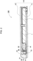
- Fig. 2 is a vertical cross-sectional view taken along line II-II in Fig. 1
- Fig. 3 is an enlarged cross-sectional view of relevant parts illustrated in Fig. 2 .
- Battery pack 100 illustrated in these figures includes one or more secondary battery cells 1, terminal part 20, terminal holder 30 connected to this terminal part 20, and outer covering case 10.
- Outer covering case 10 stores one or more secondary battery cells 1, a battery holder, and the like.
- the exterior of this outer covering case 10 is box-shaped, as illustrated in Fig. 1 .
- Outer covering case 10 is divided in half as upper case 12 and lower case 11, for example.
- This outer covering case 10 is made of a highly insulating material that is, for example, a resin such as polycarbonate and a polycarbonate-acrylonitrile butadiene styrene (PC-ABS) alloy.
- Holder storage space 15 that stores terminal holder 30 is provided inside outer covering case 10, as illustrated in the cross-sectional views in Fig. 2 and Fig. 3 .
- Holder storage space 15 is formed between wall part 13 formed on lower case 11 of outer covering case 10 and inner block 14 located inside outer covering case 10.
- Prismatic or cylindrical secondary battery cells can be used as one or more secondary battery cells 1.
- two prismatic secondary battery cells 1 are arranged side by side when in use.
- the number, positions, etc., of secondary battery cells 1 are not limited to those applied in this example and can be set to an arbitrary number, arbitrary positions, etc., as appropriate.
- Each of secondary battery cells 1 includes positive and negative electrodes.
- the positive and negative electrodes are preferably provided on one end surface of secondary battery cell 1.
- Known secondary batteries such as lithium-ion secondary batteries, nickel-hydrogen batteries, and nickel-cadmium batteries can be used, as appropriate, as secondary battery cells 1.
- Terminal holder 30 is integrated with terminal part 20, as illustrated in the cross-sectional view in Fig. 3 .
- Fig. 4 is a cross-sectional view of terminal holder 30
- Fig. 5 illustrates this terminal holder 30 being inserted into outer covering case 10
- Fig. 6 is a perspective view of terminal holder 30,
- Fig. 7 is an exploded perspective view of terminal holder 30.
- terminal holder 30 includes resin member 31 and metal piece 32.
- Resin member 31 is formed in the shape of a plate, as illustrated in Fig. 7 . Insert-molding is applied such that metal piece 32 protrudes from a surface of this plate-shaped resin member 31, as illustrated in Fig. 4 and Fig. 7 .
- terminal part 20 has one end electrically connected to the electrodes of one or more secondary battery cells 1 and the other end exposed to the outside to form connection terminal 21, which is connected to an external element, as illustrated in Fig. 2 .
- Terminal part 20 is formed of an electrically conductive, elastic material. This terminal part 20 is bent in an L shape, as illustrated in Fig. 7 ; as a result of being bent, terminal part 20 can easily exhibit elasticity.
- terminal part 20 has one end joined to metal piece 32 of terminal holder 30 and the other end bent in a V shape. Terminal part 20 having this structure constitutes connection terminal 21 that allows the abutment of the valley portion of the V shape.
- outer covering case 10 includes open window 16 so that a portion of connection terminal 21 out of terminal part 20 is exposed to the outside, as illustrated in the cross-sectional view in Fig. 3 .
- Terminal part 20 is formed by bending a metal plate.
- two terminal parts 20 corresponding to the positive electrode and the negative electrode are joined to two metal pieces 32 protruding from terminal holder 30.
- terminal part 20 which is made of metal
- metal piece 32 which is also made of metal
- Terminal part 20 and metal piece 32 are preferably joined together by welding.
- the metals can be easily joined together. These are more preferably joined together by spot welding in which laser light or the like is used.
- Terminal holder 30 to which terminal part 20 has been integrally joined in this manner is housed in holder storage space 15, as indicated by the dashed line in Fig. 5 .
- holder storage space 815 is formed between wall part 813 formed on outer covering case 819 and inner block 814 located inside outer covering case 810.
- terminal holder 830 may wobble, leading to reduced connection stability between connection terminal 821 and a terminal of a charger, an electrical device, or the like. Therefore, the inner shape of holder storage space 815 is designed so as to match the external shape of terminal holder 830, in other words, so as to prevent wobbling.
- terminal holder 30 with terminal part 20 joined thereto has a breadth greater than the design value, which may result in the failure to be stored into holder storage space 15.
- the position of connection terminal 21 of terminal part 20 is offset from the proper position, which is undesirable from the perspective of electrical connection stability.
- improving the accuracy of the position of connection between metal piece 32 and terminal part 20 is difficult due to the issues of manufacturing intersection or the like, and may also lead to reduced yield, for example, which is disadvantageous in terms of manufacturing cost.
- recess 41 is formed at a position of a part of holder storage space 15 of outer covering case 10 that is opposite to terminal part 20.
- recess 41 is formed on a part of the inner surface of wall part 13.
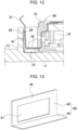
- terminal holder 30 when the breadth of terminal holder 30 with terminal part 20 joined thereto is less than the design value as illustrated in Fig. 10 , terminal holder 30 can be stored into holder storage space 15 as illustrated in Fig. 12 .
- the horizontal width thereof is set greater than at least the breadth of terminal part 20.
- the horizontal width is set great enough to allow the insertion of both of these two terminal parts 20.
- the number of recesses 41 to be formed is one, meaning that recess 41 can be easily formed, which is advantageous.
- recess 41 may be formed on insulating plate 40, which will be described later, at a position corresponding to each terminal part 20.
- the vertical length of recess 41 is set great enough to hold a portion of terminal part 20 in recess 41 when the breadth of terminal holder 30 with terminal part 20 joined thereto is greater than the design value as illustrated in Fig. 11 .
- the vertical length of recess 41 is also correlated with the thickness of protrusion 42, which will be described later, and is designed so that the angle of connection terminal 21 at the tip of terminal part 20 does not change significantly while a portion of terminal part 20 fits within recess 41.
- the vertical length of recess 41 and the thickness of protrusion 42 are designed so that angle ⁇ at which terminal part 20 is inclined with respect to the vertical direction is less than five degrees while terminal part 20 fits within recess 41.
- protrusion 42 is formed around recess 41.
- This protrusion 42 can guide terminal part 20 by abutment therewith and hold terminal part 20 so that connection terminal 21 is exposed through open window 16.
- causing terminal part 20 to abut protrusion 42 minimizes stability deterioration that occurs when recess 41 is provided on wall part 13, the area of contact with terminal part 20 is reduced, and a gap is formed between terminal part 20 and a portion of the inner surface of wall part 13.
- battery pack 100 additionally includes insulating plate 40.
- Insulating plate 40 is generally formed flat and recess 41 is formed in the middle thereof as illustrated in the perspective view in Fig. 13 .
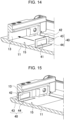
- insulating plate 40 By placing this insulating plate 40 on the inner surface of wall part 13 of holder storage space 15 as illustrated in Fig. 14 , it is possible to easily form recess 41 on outer covering case 10 as illustrated in Fig. 15 .
- wall part 13 of outer covering case 10 is designed in advance to have a thickness reduced by an amount corresponding to the thickness of insulating plate 40. Accordingly, it is possible to form recess 41 without changing the inner diameter of holder storage space 15.
- adhesive, a double-sided tape, or the like may be used to fix insulating plate 40 to wall part 13. In this situation, the thickness of wall part 13 is designed in consideration of the thickness of the adhesive, the double-sided tape, or the like.
- Insulating plate 40 is made of insulating material, making it possible to avoid unintended electrical conduction, short-circuiting, or the like while allowing the abutment of terminal part 20, which is made of metal. Insulating plate 40 can be formed as a stacked body. Thus, it is possible to easily form recess 41 by stacking, on a flat sheet, a sheet in which an opening has been formed in advance.
- the material of the sheet to be stacked may be paper, talc, or resin. Particularly, paper, which imposes less burdens on the environment, is favorable in terms of accessibility, recyclability, and the like.
- insulating plate 40 including recess 41 may be formed by resin molding.
- Insulating plate 40 may not only be formed flat, but also include first surface 43 on which recess 41 is formed and second surface 44 extending at an angle from this first surface 43, as illustrated in Fig. 13 . This makes it easy for insulating plate 40 to stand, as illustrated in Fig. 3 , etc., and also allows for improved handleability.
- recess 41 is formed by depressing first surface 43 of insulating plate 40 in the example illustrated in Fig. 3 , Fig. 13 , etc., but this configuration is not limiting; recess 41 may be formed by making an opening in insulating plate 40.
- This example is illustrated in Fig. 16 as battery pack 200 according to Embodiment 2.
- components that are substantially the same as those in Embodiment 1 described above will be assigned the same reference signs and detailed description thereof will be omitted.
- Insulating plate 40B illustrated in this figure is shaped to have an opening made by removing a portion thereof corresponding to recess 41B; when insulating plate 40B is disposed on wall part 13 of outer covering case 10, recess 41B is formed on the wall surface of holder storage space 15. With this configuration, the opening can be easily formed in insulating plate 40B, which is advantageous.
- a method for forming recess 41 on wall part 13 of outer covering case 10 may be providing wall part 13 that has been processed, other than providing another member such as insulating plate 40 described above.
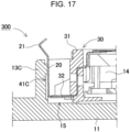
- This example is illustrated in the cross-sectional view in Fig. 17 as battery pack 300 according to Embodiment 3.
- Outer covering case 10 illustrated in Fig. 17 is formed by resin molding so that recess 41C is formed integrally with wall part 13C in advance.
- die cutting is complex, but can be realized using a slide mold or the like. With this configuration, it is not necessary to prepare another member such as an insulating plate and thus, the manufacturing process can be simplified, which is advantageous.
- the drawback is increased cost of the die.
- terminal part 20 is joined to metal piece 32 by spot welding.
- terminal holder 30 is positioned in holder storage space 15 to assume a posture that causes a portion of terminal part 20 to face recess 41 formed on a part of holder storage space 15 of outer covering case 10.
- the battery pack according to the present invention can be favorably used as a power supply for radios or a power supply for portable electrical devices such as an electrical cleaner and an electric tool, for example. Furthermore, the battery pack can also be used, as appropriate, as a power supply device for vehicles such as an electric assisted bicycle and an electric cart, for example.
Landscapes
- Chemical & Material Sciences (AREA)
- Chemical Kinetics & Catalysis (AREA)
- Electrochemistry (AREA)
- General Chemical & Material Sciences (AREA)
- Battery Mounting, Suspending (AREA)
- Connection Of Batteries Or Terminals (AREA)
- Sealing Battery Cases Or Jackets (AREA)
Abstract
Description
- The present disclosure relates to battery packs.
- In an electrical device that uses a chargeable secondary battery such as a lithium-ion secondary battery, a battery pack is used in which two or more secondary battery cells are stored in such a manner that the secondary battery can be replaced (for example, Patent Literature (PTL) 1). The battery pack connected to the electrical device or having been detached from the electrical device and fitted into a dedicated charger is charged.
- Such a battery pack requires an electrical contact to connect to a battery pack body or a charger that charges the battery pack. In order to ensure stable electrical connection at the electrical contact, a connection terminal of the battery pack or charger is often elastic.
- Suppose now that a connection terminal of the battery pack is made elastic. Upon attachment of such an elastic connection terminal to the battery pack, first, the connection terminal is set on a terminal holder in place to build a holder assembly, and then the holder assembly is fitted to the casing of the battery pack.
- However, with the conventional battery pack, if the mounting position of the connection terminal on the terminal holder varies when building the holder assembly, the terminal holder may not be properly positioned with respect to the casing of the battery pack during assembling, which is problematic.
- PTL 1: Unexamined
Japanese Patent Publication No. H06-333547 - One object of the present disclosure is to provide a battery pack that can be assembled even if the mounting position of a terminal on a terminal holder varies.
- A battery pack according to one embodiment of the present invention includes: one or more secondary battery cells each including electrodes that are positive and negative; a terminal that is made of metal and is electrically connected to the electrodes of the one or more secondary battery cells; a terminal holder integrated with the terminal; and an outer covering case that stores the one or more secondary battery cells and includes a holder storage space that stores the terminal holder. The outer covering case is a part of the holder storage space and includes a recess at a position opposite the terminal.
- A battery pack manufacturing method according to another embodiment of the present invention is a method for manufacturing a battery pack including: one or more secondary battery cells each including electrodes that are positive and negative; a terminal that is made of metal and is electrically connected to the electrodes of the one or more secondary battery cells; a terminal holder including a resin member and a metal piece protruding from a surface of the resin member, the terminal holder being integrated with the terminal; and an outer covering case that stores the one or more secondary battery cells and includes a holder storage space that stores the terminal holder. The method includes: joining the terminal to the metal piece by spot welding; and positioning the terminal holder in the holder storage space to assume a posture that causes a portion of the terminal to face a recess formed on a part of the holder storage space of the outer covering case.
- With the battery pack according to one embodiment of the present invention, even if the mounting position of the terminal on the terminal holder varies when integrating the terminal and the terminal holder, the terminal is inserted into a portion of the recess formed at the position opposite the terminal, thus the variations can be absorbed, and the terminal holder can be stored into the holder storage space.
-
- [
Fig. 1] Fig. 1 is a perspective view of a battery pack according toEmbodiment 1 of the present invention. - [
Fig. 2] Fig. 2 is a vertical cross-sectional view taken along line II-II inFig. 1 . - [
Fig. 3] Fig. 3 is an enlarged cross-sectional view of relevant parts illustrated inFig. 2 . - [
Fig. 4] Fig. 4 is a cross-sectional view illustrating a terminal holder illustrated inFig. 3 . - [
Fig. 5] Fig. 5 is an enlarged cross-sectional view illustrating a terminal holder being inserted into an outer covering case illustrated inFig. 3 . - [
Fig. 6] Fig. 6 is a perspective view of a terminal holder. - [
Fig. 7] Fig. 7 is an exploded perspective view of a terminal holder. - [
Fig. 8] Fig. 8 is an enlarged cross-sectional view of relevant parts of a battery pack according to a comparative example. - [
Fig. 9] Fig. 9 is a cross-sectional view illustrating the position of connection between a terminal holder and a terminal part illustrated inFig. 4 being offset to the left. - [
Fig. 10] Fig. 10 is a cross-sectional view illustrating the position of connection between a terminal holder and a terminal part illustrated inFig. 4 being offset to the right. - [
Fig. 11] Fig. 11 is an enlarged cross-sectional view illustrating a terminal holder illustrated inFig. 9 being inserted into an outer covering case. - [
Fig. 12] Fig. 12 is an enlarged cross-sectional view illustrating a terminal holder illustrated inFig. 10 being inserted into an outer covering case. - [
Fig. 13] Fig. 13 is a perspective view of an insulating plate. - [
Fig. 14] Fig. 14 is an exploded perspective view illustrating an insulating plate being placed on a wall part. - [
Fig. 15] Fig. 15 is an enlarged cross-sectional view illustrating an insulating plate having been placed on a wall part. - [
Fig. 16] Fig. 16 is an enlarged cross-sectional view of relevant parts of a battery pack according to Embodiment 2 of the present invention. - [
Fig. 17] Fig. 17 is an enlarged cross-sectional view of relevant parts of a battery pack according to Embodiment 2 of the present invention. - Embodiments of the present invention may be specified by configurations, features, and the like indicated below.
- A battery pack according to another embodiment of the present invention may be configured in any one of the aforementioned embodiments so that a protrusion is formed around the recess, and the terminal part abuts the protrusion.
- Furthermore, in any one of the aforementioned embodiments, a battery pack according to another embodiment of the present invention may further include an insulating plate that is insulative and is disposed on a wall surface of the holder storage space, and the recess may be formed on the insulating plate. With this configuration, it is possible to easily form the recess in the holder storage space of the outer covering case by adding another member including a recess to the outer covering case.
- Moreover, in a battery pack according to another embodiment of the present invention, a plurality of paper sheets may be stacked to form the insulating plate in any one of the aforementioned embodiments.
- Moreover, in a battery pack according to another embodiment of the present invention, the insulating plate may include: a first surface on which the recess is formed; and a second surface extending at an angle from the first surface in any one of the aforementioned embodiments.
- Moreover, in a battery pack according to another embodiment of the present invention, the terminal holder may include: a resin member; and a metal piece protruding from a surface of the resin member, and the terminal part may be joined to the metal piece and integrated with the terminal holder in any one of the aforementioned embodiments.
- Moreover, in a battery pack according to another embodiment of the present invention, the terminal part may be joined to the metal piece by spot welding in any one of the aforementioned embodiments.
- Moreover, in a battery pack according to another embodiment of the present invention, the terminal part may be bent in an L shape, may be joined to the metal piece at one end, may be bent in a V shape at the other end, and may include a connection terminal that is connected to an external element in any one of the aforementioned embodiments.
- Hereinafter, exemplary embodiments of the present invention will be described with reference to the drawings. Note that the exemplary embodiments described below are mere illustrations for embodying the technical idea of the present invention; the present invention is not limited to those described below. The present specification should not be considered limiting in any way the members recited in the claims to the members indicated in the exemplary embodiments. In particular, the dimensions, materials, shapes, relative positioning, etc., of components indicated in the exemplary embodiments are not intended to limit the scope of the present invention thereto, but are merely exemplary, unless specifically noted otherwise. Note that there are cases where the size, positional relationship, etc., of the members illustrated in the drawings are exaggerated for clarity of explanation. Furthermore, in the following description, the same name and reference signs indicate the same or similar members, and detailed description thereof will be omitted, as appropriate. Moreover, the elements included in the present invention may be realized by forming two or more elements out of the same member so that one member functions as two or more elements or by allocating the functions of one member to two or more members.
- The battery pack according to the present invention can be used as a power supply for portable electrical devices such as a radio, an electrical cleaner, and an electric tool, or as a backup power supply of a server for stationary energy storage usage or a power supply device for homes, offices, and factories, and can also be used as a power supply for driving an electric assisted bicycle or as a power supply for driving vehicles such as an electric scooter, an electric cart, a hybrid vehicle, and an electric vehicle, for example. As one exemplary embodiment of the present invention, a battery pack to be used as a power supply for portable radios will be described below.
-
Fig. 1 to Fig. 3 illustrate battery pack 100 according toEmbodiment 1 of the present invention. In these figures,Fig. 1 is a perspective view ofbattery pack 100 according toEmbodiment 1 of the present invention,Fig. 2 is a vertical cross-sectional view taken along line II-II inFig. 1 , andFig. 3 is an enlarged cross-sectional view of relevant parts illustrated inFig. 2 .Battery pack 100 illustrated in these figures includes one or moresecondary battery cells 1,terminal part 20,terminal holder 30 connected to thisterminal part 20, andouter covering case 10. - Outer covering
case 10 stores one or moresecondary battery cells 1, a battery holder, and the like. The exterior of thisouter covering case 10 is box-shaped, as illustrated inFig. 1 .Outer covering case 10 is divided in half asupper case 12 andlower case 11, for example. Thisouter covering case 10 is made of a highly insulating material that is, for example, a resin such as polycarbonate and a polycarbonate-acrylonitrile butadiene styrene (PC-ABS) alloy.Holder storage space 15 that storesterminal holder 30 is provided insideouter covering case 10, as illustrated in the cross-sectional views inFig. 2 andFig. 3 .Holder storage space 15 is formed betweenwall part 13 formed onlower case 11 ofouter covering case 10 andinner block 14 located insideouter covering case 10. - Prismatic or cylindrical secondary battery cells can be used as one or more
secondary battery cells 1. In the example illustrated inFig. 2 , two prismaticsecondary battery cells 1 are arranged side by side when in use. Note that the number, positions, etc., ofsecondary battery cells 1 are not limited to those applied in this example and can be set to an arbitrary number, arbitrary positions, etc., as appropriate. Each ofsecondary battery cells 1 includes positive and negative electrodes. The positive and negative electrodes are preferably provided on one end surface ofsecondary battery cell 1. Known secondary batteries such as lithium-ion secondary batteries, nickel-hydrogen batteries, and nickel-cadmium batteries can be used, as appropriate, assecondary battery cells 1. -
Terminal holder 30 is integrated withterminal part 20, as illustrated in the cross-sectional view inFig. 3 .Fig. 4 is a cross-sectional view ofterminal holder 30,Fig. 5 illustrates thisterminal holder 30 being inserted intoouter covering case 10,Fig. 6 is a perspective view ofterminal holder 30, andFig. 7 is an exploded perspective view ofterminal holder 30. As illustrated in these figures,terminal holder 30 includesresin member 31 andmetal piece 32.Resin member 31 is formed in the shape of a plate, as illustrated inFig. 7 . Insert-molding is applied such thatmetal piece 32 protrudes from a surface of this plate-shapedresin member 31, as illustrated inFig. 4 andFig. 7 . - Meanwhile,
terminal part 20 has one end electrically connected to the electrodes of one or moresecondary battery cells 1 and the other end exposed to the outside to formconnection terminal 21, which is connected to an external element, as illustrated inFig. 2 .Terminal part 20 is formed of an electrically conductive, elastic material. Thisterminal part 20 is bent in an L shape, as illustrated inFig. 7 ; as a result of being bent,terminal part 20 can easily exhibit elasticity. Furthermore,terminal part 20 has one end joined tometal piece 32 ofterminal holder 30 and the other end bent in a V shape.Terminal part 20 having this structure constitutesconnection terminal 21 that allows the abutment of the valley portion of the V shape. Furthermore,outer covering case 10 includesopen window 16 so that a portion ofconnection terminal 21 out ofterminal part 20 is exposed to the outside, as illustrated in the cross-sectional view inFig. 3 . -
Terminal part 20 is formed by bending a metal plate. In the example illustrated inFig. 6 and Fig. 7 , twoterminal parts 20 corresponding to the positive electrode and the negative electrode are joined to twometal pieces 32 protruding fromterminal holder 30. In this manner,terminal part 20, which is made of metal, is joined tometal piece 32, which is also made of metal, and is thus integrated withterminal holder 30.Terminal part 20 andmetal piece 32 are preferably joined together by welding. Thus, the metals can be easily joined together. These are more preferably joined together by spot welding in which laser light or the like is used.Terminal holder 30 to whichterminal part 20 has been integrally joined in this manner is housed inholder storage space 15, as indicated by the dashed line inFig. 5 . - If a mismatch occurs between the welding position and the design position when welding
terminal part 20 andmetal piece 32 together, there may be a situation where these cannot be stored intoholder storage space 15. As illustrated in the cross-sectional view ofbattery pack 800 according to the comparative example illustrated inFig. 8 ,holder storage space 815 is formed betweenwall part 813 formed on outer covering case 819 andinner block 814 located insideouter covering case 810. When there is a gap between the exterior ofterminal holder 830 and the inner surface ofholder storage space 815 whileterminal holder 830 is stored inholder storage space 815,terminal holder 830 may wobble, leading to reduced connection stability betweenconnection terminal 821 and a terminal of a charger, an electrical device, or the like. Therefore, the inner shape ofholder storage space 815 is designed so as to match the external shape ofterminal holder 830, in other words, so as to prevent wobbling. - When the position of connection between
metal piece 32 andterminal part 20 is offset from the proper design position to the left as indicated by the arrow inFig. 9 ,terminal holder 30 withterminal part 20 joined thereto has a breadth greater than the design value, which may result in the failure to be stored intoholder storage space 15. On the other hand, when the position of connection betweenmetal piece 32 andterminal part 20 is adjusted and ends up being offset from the proper design position further to the right as indicated by the arrow inFig. 10 , the position ofconnection terminal 21 ofterminal part 20 is offset from the proper position, which is undesirable from the perspective of electrical connection stability. However, improving the accuracy of the position of connection betweenmetal piece 32 andterminal part 20 is difficult due to the issues of manufacturing intersection or the like, and may also lead to reduced yield, for example, which is disadvantageous in terms of manufacturing cost. - In view of this, in
battery pack 100 according to the present exemplary embodiment,recess 41 is formed at a position of a part ofholder storage space 15 ofouter covering case 10 that is opposite toterminal part 20. In the example illustrated in the cross-sectional view inFig. 3 ,recess 41 is formed on a part of the inner surface ofwall part 13. With this configuration, even whenterminal holder 30 withterminal part 20 joined thereto has a breadth greater than the design value and cannot be simply stored intoholder storage space 15 as illustrated inFig. 9 , it is possible to storeterminal holder 30 intoholder storage space 15 by inserting a portion ofterminal part 20 intorecess 41 as illustrated inFig. 11 . In this manner, even when the position at whichterminal part 20 is fixed toterminal holder 30 varies, the variations can be absorbed atrecess 41 and thus, even thisterminal holder 30 can be stored intoholder storage space 15. - Furthermore, when the breadth of
terminal holder 30 withterminal part 20 joined thereto is less than the design value as illustrated inFig. 10 ,terminal holder 30 can be stored intoholder storage space 15 as illustrated inFig. 12 . - Regarding the size of
recess 41, the horizontal width thereof is set greater than at least the breadth ofterminal part 20. When twoterminal parts 20 for the positive electrode and the negative electrode are provided as illustrated inFig. 6 , the horizontal width is set great enough to allow the insertion of both of these twoterminal parts 20. As a result, the number ofrecesses 41 to be formed is one, meaning thatrecess 41 can be easily formed, which is advantageous. Note that when two or moreterminal parts 20 are provided,recess 41 may be formed on insulatingplate 40, which will be described later, at a position corresponding to eachterminal part 20. When two or more relativelysmall recesses 41 corresponding to the sizes of respectiveterminal parts 20 are formed in this manner, the strength of insulatingplate 40 can be maintained as compared to the configuration in which singlelarge recess 41 is formed. - The vertical length of
recess 41 is set great enough to hold a portion ofterminal part 20 inrecess 41 when the breadth ofterminal holder 30 withterminal part 20 joined thereto is greater than the design value as illustrated inFig. 11 . The vertical length ofrecess 41 is also correlated with the thickness ofprotrusion 42, which will be described later, and is designed so that the angle ofconnection terminal 21 at the tip ofterminal part 20 does not change significantly while a portion ofterminal part 20 fits withinrecess 41. In other words, when the vertical length ofrecess 41 is too small, the tilt angle ofterminal part 20 in abutment withprotrusion 42 is large and as a result, the position ofconnection terminal 21 is significantly offset. For example, the vertical length ofrecess 41 and the thickness ofprotrusion 42 are designed so that angle θ at whichterminal part 20 is inclined with respect to the vertical direction is less than five degrees whileterminal part 20 fits withinrecess 41. - As a result of providing
recess 41 on a portion of the inner surface ofwall part 13,protrusion 42 is formed aroundrecess 41. Thisprotrusion 42 can guideterminal part 20 by abutment therewith and holdterminal part 20 so thatconnection terminal 21 is exposed throughopen window 16. In other words, causingterminal part 20 toabut protrusion 42 minimizes stability deterioration that occurs whenrecess 41 is provided onwall part 13, the area of contact withterminal part 20 is reduced, and a gap is formed betweenterminal part 20 and a portion of the inner surface ofwall part 13. - In order to allow
recess 41 to be easily formed onwall part 13 ofholder storage space 15,battery pack 100 according toEmbodiment 1 additionally includes insulatingplate 40. Insulatingplate 40 is generally formed flat andrecess 41 is formed in the middle thereof as illustrated in the perspective view inFig. 13 . By placing this insulatingplate 40 on the inner surface ofwall part 13 ofholder storage space 15 as illustrated inFig. 14 , it is possible to easily formrecess 41 onouter covering case 10 as illustrated inFig. 15 . Note thatwall part 13 ofouter covering case 10 is designed in advance to have a thickness reduced by an amount corresponding to the thickness of insulatingplate 40. Accordingly, it is possible to formrecess 41 without changing the inner diameter ofholder storage space 15. Note that adhesive, a double-sided tape, or the like may be used to fix insulatingplate 40 to wallpart 13. In this situation, the thickness ofwall part 13 is designed in consideration of the thickness of the adhesive, the double-sided tape, or the like. - Insulating
plate 40 is made of insulating material, making it possible to avoid unintended electrical conduction, short-circuiting, or the like while allowing the abutment ofterminal part 20, which is made of metal. Insulatingplate 40 can be formed as a stacked body. Thus, it is possible to easily formrecess 41 by stacking, on a flat sheet, a sheet in which an opening has been formed in advance. The material of the sheet to be stacked may be paper, talc, or resin. Particularly, paper, which imposes less burdens on the environment, is favorable in terms of accessibility, recyclability, and the like. Furthermore, insulatingplate 40 includingrecess 41 may be formed by resin molding. - Insulating
plate 40 may not only be formed flat, but also includefirst surface 43 on whichrecess 41 is formed andsecond surface 44 extending at an angle from thisfirst surface 43, as illustrated inFig. 13 . This makes it easy for insulatingplate 40 to stand, as illustrated inFig. 3 , etc., and also allows for improved handleability. - Note that
recess 41 is formed by depressingfirst surface 43 of insulatingplate 40 in the example illustrated inFig. 3 ,Fig. 13 , etc., but this configuration is not limiting;recess 41 may be formed by making an opening in insulatingplate 40. This example is illustrated inFig. 16 asbattery pack 200 according to Embodiment 2. In this figure, components that are substantially the same as those inEmbodiment 1 described above will be assigned the same reference signs and detailed description thereof will be omitted. Insulatingplate 40B illustrated in this figure is shaped to have an opening made by removing a portion thereof corresponding to recess 41B; when insulatingplate 40B is disposed onwall part 13 ofouter covering case 10,recess 41B is formed on the wall surface ofholder storage space 15. With this configuration, the opening can be easily formed in insulatingplate 40B, which is advantageous. - A method for forming
recess 41 onwall part 13 ofouter covering case 10 may be providingwall part 13 that has been processed, other than providing another member such as insulatingplate 40 described above. This example is illustrated in the cross-sectional view inFig. 17 asbattery pack 300 according to Embodiment 3. In this figure, components that are substantially the same as those inEmbodiment 1 described above will be assigned the same reference signs and detailed description thereof will be omitted.Outer covering case 10 illustrated inFig. 17 is formed by resin molding so thatrecess 41C is formed integrally withwall part 13C in advance. In this situation, die cutting is complex, but can be realized using a slide mold or the like. With this configuration, it is not necessary to prepare another member such as an insulating plate and thus, the manufacturing process can be simplified, which is advantageous. The drawback is increased cost of the die. - A method for assembling
battery pack 100 described above will be described below. First,terminal part 20 is joined tometal piece 32 by spot welding. Next,terminal holder 30 is positioned inholder storage space 15 to assume a posture that causes a portion ofterminal part 20 to facerecess 41 formed on a part ofholder storage space 15 ofouter covering case 10. Thus, even if the mounting position ofterminal part 20 onterminal holder 30 varies when integratingterminal part 20 andterminal holder 30,terminal part 20 is inserted into a portion ofrecess 41 formed at the position oppositeterminal part 20, thus the variations can be absorbed, andterminal holder 30 can be stored intoholder storage space 15. - The battery pack according to the present invention can be favorably used as a power supply for radios or a power supply for portable electrical devices such as an electrical cleaner and an electric tool, for example. Furthermore, the battery pack can also be used, as appropriate, as a power supply device for vehicles such as an electric assisted bicycle and an electric cart, for example.
-
- 100, 200, 300, 800 battery pack
- 1 secondary battery cell
- 10 outer covering case
- 11 lower case
- 12 upper case
- 13, 13C wall part
- 14 inner block
- 15 holder storage space
- 16 open window
- 20 terminal part
- 21 connection terminal
- 30 terminal holder
- 31 resin member
- 32 metal piece
- 40, 40B insulating plate
- 41, 41B, 41C recess
- 42 protrusion
- 43 first surface
- 44 second surface
Claims (9)
- A battery pack comprising:one or more secondary battery cells each including electrodes that are positive and negative;a terminal that is made of metal and is electrically connected to the electrodes of the one or more secondary battery cells;a terminal holder integrated with the terminal; andan outer covering case that stores the one or more secondary battery cells and includes a holder storage space that stores the terminal holder, whereinthe outer covering case is a part of the holder storage space and includes a recess facing the terminal.
- The battery pack according to claim 1, further comprising:a protrusion around the recess, whereinthe terminal abuts the protrusion.
- The battery pack according to claim 1, further comprising:an insulating plate that is insulative and is disposed on a wall surface of the holder storage space, whereinthe recess is on the insulating plate.
- The battery pack according to claim 3, wherein
the insulating plate includes a plurality of paper sheets that are stacked. - The battery pack according to claim 3, wherein
the insulating plate includes:a first surface including the recess; anda second surface extending at an angle from the first surface. - The battery pack according to any one of claims 1 to 5, whereinthe terminal holder includes:a resin member; anda metal piece protruding from a surface of the resin member, andthe terminal is joined to the metal piece and integrated with the terminal holder.
- The battery pack according to claim 6, wherein
the terminal is joined to the metal piece by spot welding. - The battery pack according to claim 6, wherein
the terminal is bent in an L shape, is joined to the metal piece at one end, is bent in a V shape at an other end, and includes a connection terminal that is connected to an external element. - A method for manufacturing a battery pack including:one or more secondary battery cells each including electrodes that are positive and negative;a terminal that is made of metal and is electrically connected to the electrodes of the one or more secondary battery cells;a terminal holder including a resin member and a metal piece protruding from a surface of the resin member, the terminal holder being integrated with the terminal; andan outer covering case that stores the one or more secondary battery cells and includes a holder storage space that stores the terminal holder, the method comprising:joining the terminal to the metal piece by spot welding; andpositioning the terminal holder in the holder storage space to cause a portion of the terminal to face a recess on a part of the holder storage space of the outer covering case.
Applications Claiming Priority (2)
| Application Number | Priority Date | Filing Date | Title |
|---|---|---|---|
| JP2022105055 | 2022-06-29 | ||
| PCT/JP2023/020417 WO2024004506A1 (en) | 2022-06-29 | 2023-06-01 | Battery pack |
Publications (2)
| Publication Number | Publication Date |
|---|---|
| EP4550550A1 true EP4550550A1 (en) | 2025-05-07 |
| EP4550550A4 EP4550550A4 (en) | 2025-10-22 |
Family
ID=89382685
Family Applications (1)
| Application Number | Title | Priority Date | Filing Date |
|---|---|---|---|
| EP23830956.1A Pending EP4550550A4 (en) | 2022-06-29 | 2023-06-01 | BATTERY PACK |
Country Status (6)
| Country | Link |
|---|---|
| US (1) | US20250357612A1 (en) |
| EP (1) | EP4550550A4 (en) |
| JP (1) | JPWO2024004506A1 (en) |
| CN (1) | CN119404360A (en) |
| TW (1) | TW202412379A (en) |
| WO (1) | WO2024004506A1 (en) |
Family Cites Families (5)
| Publication number | Priority date | Publication date | Assignee | Title |
|---|---|---|---|---|
| JPH0416362Y2 (en) * | 1986-05-13 | 1992-04-13 | ||
| JPH06333547A (en) * | 1993-05-19 | 1994-12-02 | Sanyo Electric Co Ltd | Battery pack |
| JP2000277076A (en) * | 1999-03-26 | 2000-10-06 | Tookado:Kk | Battery pack electrode mounting structure |
| JP6191795B1 (en) * | 2017-02-10 | 2017-09-06 | ソニー株式会社 | Battery and connected equipment |
| WO2019057187A1 (en) * | 2017-09-22 | 2019-03-28 | 苏州宝时得电动工具有限公司 | Battery pack and electric tool assembly |
-
2023
- 2023-06-01 JP JP2024530589A patent/JPWO2024004506A1/ja active Pending
- 2023-06-01 EP EP23830956.1A patent/EP4550550A4/en active Pending
- 2023-06-01 CN CN202380049526.6A patent/CN119404360A/en active Pending
- 2023-06-01 WO PCT/JP2023/020417 patent/WO2024004506A1/en not_active Ceased
- 2023-06-01 US US18/877,287 patent/US20250357612A1/en active Pending
- 2023-06-13 TW TW112122015A patent/TW202412379A/en unknown
Also Published As
| Publication number | Publication date |
|---|---|
| JPWO2024004506A1 (en) | 2024-01-04 |
| WO2024004506A1 (en) | 2024-01-04 |
| CN119404360A (en) | 2025-02-07 |
| TW202412379A (en) | 2024-03-16 |
| US20250357612A1 (en) | 2025-11-20 |
| EP4550550A4 (en) | 2025-10-22 |
Similar Documents
| Publication | Publication Date | Title |
|---|---|---|
| US10625619B2 (en) | Battery module, battery pack comprising battery module, and vehicle comprising battery pack | |
| US11450930B2 (en) | Battery module and battery pack having same | |
| EP4730514A1 (en) | Battery module, battery pack including battery module, and vehicle including battery pack | |
| EP2811545B1 (en) | Battery module | |
| EP2498318B1 (en) | Battery pack | |
| EP2432048B1 (en) | Stacked cell and method for manufacturing same | |
| CN101689625B (en) | battery structure | |
| KR101649138B1 (en) | Rechargeable battery | |
| EP3561902A1 (en) | Battery module, battery pack comprising battery module, and vehicle comprising battery pack | |
| KR101275785B1 (en) | Secondary battery | |
| JP6454423B2 (en) | Battery cell and battery system | |
| KR20190007745A (en) | Battery pack | |
| KR20180032083A (en) | Rechageable battery | |
| EP3664185A1 (en) | Electric-equipment assembly and battery pack comprising same | |
| US11424516B2 (en) | Battery pack and production method for same | |
| JP5512152B2 (en) | Pack battery | |
| US20250357612A1 (en) | Battery pack | |
| EP3159959A1 (en) | Battery cell including battery case having projecting portion formed thereon corresponding to step-structured electrode assembly | |
| EP4106096B1 (en) | Connection member, battery cell, battery, and electrical device | |
| EP4597731A1 (en) | Electric device and method of manufacturing same | |
| JP2024138573A (en) | Battery module and manufacturing method thereof | |
| EP4645556A1 (en) | Battery pack and method for manufacturing same | |
| EP4489197B1 (en) | Battery pack | |
| CN219350588U (en) | Single battery and battery pack | |
| EP4489196A1 (en) | Battery pack |
Legal Events
| Date | Code | Title | Description |
|---|---|---|---|
| STAA | Information on the status of an ep patent application or granted ep patent |
Free format text: STATUS: THE INTERNATIONAL PUBLICATION HAS BEEN MADE |
|
| PUAI | Public reference made under article 153(3) epc to a published international application that has entered the european phase |
Free format text: ORIGINAL CODE: 0009012 |
|
| STAA | Information on the status of an ep patent application or granted ep patent |
Free format text: STATUS: REQUEST FOR EXAMINATION WAS MADE |
|
| 17P | Request for examination filed |
Effective date: 20250109 |
|
| AK | Designated contracting states |
Kind code of ref document: A1 Designated state(s): AL AT BE BG CH CY CZ DE DK EE ES FI FR GB GR HR HU IE IS IT LI LT LU LV MC ME MK MT NL NO PL PT RO RS SE SI SK SM TR |
|
| DAV | Request for validation of the european patent (deleted) | ||
| DAX | Request for extension of the european patent (deleted) | ||
| A4 | Supplementary search report drawn up and despatched |
Effective date: 20250918 |
|
| RIC1 | Information provided on ipc code assigned before grant |
Ipc: H01M 50/296 20210101AFI20250912BHEP Ipc: H01M 50/588 20210101ALI20250912BHEP Ipc: H01M 50/593 20210101ALI20250912BHEP Ipc: H01M 50/298 20210101ALI20250912BHEP Ipc: H01M 50/207 20210101ALI20250912BHEP |