EP4550495A1 - Battery module comprising elastic plate and battery pack comprising the same - Google Patents
Battery module comprising elastic plate and battery pack comprising the same Download PDFInfo
- Publication number
- EP4550495A1 EP4550495A1 EP24197496.3A EP24197496A EP4550495A1 EP 4550495 A1 EP4550495 A1 EP 4550495A1 EP 24197496 A EP24197496 A EP 24197496A EP 4550495 A1 EP4550495 A1 EP 4550495A1
- Authority
- EP
- European Patent Office
- Prior art keywords
- battery
- elastic plate
- buffer portion
- battery cell
- battery module
- Prior art date
- Legal status (The legal status is an assumption and is not a legal conclusion. Google has not performed a legal analysis and makes no representation as to the accuracy of the status listed.)
- Granted
Links
Images




Classifications
-
- H—ELECTRICITY
- H01—ELECTRIC ELEMENTS
- H01M—PROCESSES OR MEANS, e.g. BATTERIES, FOR THE DIRECT CONVERSION OF CHEMICAL ENERGY INTO ELECTRICAL ENERGY
- H01M50/00—Constructional details or processes of manufacture of the non-active parts of electrochemical cells other than fuel cells, e.g. hybrid cells
- H01M50/20—Mountings; Secondary casings or frames; Racks, modules or packs; Suspension devices; Shock absorbers; Transport or carrying devices; Holders
- H01M50/233—Mountings; Secondary casings or frames; Racks, modules or packs; Suspension devices; Shock absorbers; Transport or carrying devices; Holders characterised by physical properties of casings or racks, e.g. dimensions
- H01M50/242—Mountings; Secondary casings or frames; Racks, modules or packs; Suspension devices; Shock absorbers; Transport or carrying devices; Holders characterised by physical properties of casings or racks, e.g. dimensions adapted for protecting batteries against vibrations, collision impact or swelling
-
- H—ELECTRICITY
- H01—ELECTRIC ELEMENTS
- H01M—PROCESSES OR MEANS, e.g. BATTERIES, FOR THE DIRECT CONVERSION OF CHEMICAL ENERGY INTO ELECTRICAL ENERGY
- H01M10/00—Secondary cells; Manufacture thereof
- H01M10/04—Construction or manufacture in general
- H01M10/0468—Compression means for stacks of electrodes and separators
-
- H—ELECTRICITY
- H01—ELECTRIC ELEMENTS
- H01M—PROCESSES OR MEANS, e.g. BATTERIES, FOR THE DIRECT CONVERSION OF CHEMICAL ENERGY INTO ELECTRICAL ENERGY
- H01M10/00—Secondary cells; Manufacture thereof
- H01M10/04—Construction or manufacture in general
- H01M10/0481—Compression means other than compression means for stacks of electrodes and separators
-
- H—ELECTRICITY
- H01—ELECTRIC ELEMENTS
- H01M—PROCESSES OR MEANS, e.g. BATTERIES, FOR THE DIRECT CONVERSION OF CHEMICAL ENERGY INTO ELECTRICAL ENERGY
- H01M50/00—Constructional details or processes of manufacture of the non-active parts of electrochemical cells other than fuel cells, e.g. hybrid cells
- H01M50/10—Primary casings; Jackets or wrappings
- H01M50/147—Lids or covers
-
- H—ELECTRICITY
- H01—ELECTRIC ELEMENTS
- H01M—PROCESSES OR MEANS, e.g. BATTERIES, FOR THE DIRECT CONVERSION OF CHEMICAL ENERGY INTO ELECTRICAL ENERGY
- H01M50/00—Constructional details or processes of manufacture of the non-active parts of electrochemical cells other than fuel cells, e.g. hybrid cells
- H01M50/20—Mountings; Secondary casings or frames; Racks, modules or packs; Suspension devices; Shock absorbers; Transport or carrying devices; Holders
- H01M50/204—Racks, modules or packs for multiple batteries or multiple cells
-
- H—ELECTRICITY
- H01—ELECTRIC ELEMENTS
- H01M—PROCESSES OR MEANS, e.g. BATTERIES, FOR THE DIRECT CONVERSION OF CHEMICAL ENERGY INTO ELECTRICAL ENERGY
- H01M50/00—Constructional details or processes of manufacture of the non-active parts of electrochemical cells other than fuel cells, e.g. hybrid cells
- H01M50/20—Mountings; Secondary casings or frames; Racks, modules or packs; Suspension devices; Shock absorbers; Transport or carrying devices; Holders
- H01M50/204—Racks, modules or packs for multiple batteries or multiple cells
- H01M50/207—Racks, modules or packs for multiple batteries or multiple cells characterised by their shape
- H01M50/209—Racks, modules or packs for multiple batteries or multiple cells characterised by their shape adapted for prismatic or rectangular cells
-
- H—ELECTRICITY
- H01—ELECTRIC ELEMENTS
- H01M—PROCESSES OR MEANS, e.g. BATTERIES, FOR THE DIRECT CONVERSION OF CHEMICAL ENERGY INTO ELECTRICAL ENERGY
- H01M50/00—Constructional details or processes of manufacture of the non-active parts of electrochemical cells other than fuel cells, e.g. hybrid cells
- H01M50/20—Mountings; Secondary casings or frames; Racks, modules or packs; Suspension devices; Shock absorbers; Transport or carrying devices; Holders
- H01M50/258—Modular batteries; Casings provided with means for assembling
-
- H—ELECTRICITY
- H01—ELECTRIC ELEMENTS
- H01M—PROCESSES OR MEANS, e.g. BATTERIES, FOR THE DIRECT CONVERSION OF CHEMICAL ENERGY INTO ELECTRICAL ENERGY
- H01M50/00—Constructional details or processes of manufacture of the non-active parts of electrochemical cells other than fuel cells, e.g. hybrid cells
- H01M50/20—Mountings; Secondary casings or frames; Racks, modules or packs; Suspension devices; Shock absorbers; Transport or carrying devices; Holders
- H01M50/262—Mountings; Secondary casings or frames; Racks, modules or packs; Suspension devices; Shock absorbers; Transport or carrying devices; Holders with fastening means, e.g. locks
- H01M50/264—Mountings; Secondary casings or frames; Racks, modules or packs; Suspension devices; Shock absorbers; Transport or carrying devices; Holders with fastening means, e.g. locks for cells or batteries, e.g. straps, tie rods or peripheral frames
-
- H—ELECTRICITY
- H01—ELECTRIC ELEMENTS
- H01M—PROCESSES OR MEANS, e.g. BATTERIES, FOR THE DIRECT CONVERSION OF CHEMICAL ENERGY INTO ELECTRICAL ENERGY
- H01M50/00—Constructional details or processes of manufacture of the non-active parts of electrochemical cells other than fuel cells, e.g. hybrid cells
- H01M50/20—Mountings; Secondary casings or frames; Racks, modules or packs; Suspension devices; Shock absorbers; Transport or carrying devices; Holders
- H01M50/289—Mountings; Secondary casings or frames; Racks, modules or packs; Suspension devices; Shock absorbers; Transport or carrying devices; Holders characterised by spacing elements or positioning means within frames, racks or packs
- H01M50/291—Mountings; Secondary casings or frames; Racks, modules or packs; Suspension devices; Shock absorbers; Transport or carrying devices; Holders characterised by spacing elements or positioning means within frames, racks or packs characterised by their shape
-
- H—ELECTRICITY
- H01—ELECTRIC ELEMENTS
- H01M—PROCESSES OR MEANS, e.g. BATTERIES, FOR THE DIRECT CONVERSION OF CHEMICAL ENERGY INTO ELECTRICAL ENERGY
- H01M50/00—Constructional details or processes of manufacture of the non-active parts of electrochemical cells other than fuel cells, e.g. hybrid cells
- H01M50/20—Mountings; Secondary casings or frames; Racks, modules or packs; Suspension devices; Shock absorbers; Transport or carrying devices; Holders
- H01M50/289—Mountings; Secondary casings or frames; Racks, modules or packs; Suspension devices; Shock absorbers; Transport or carrying devices; Holders characterised by spacing elements or positioning means within frames, racks or packs
- H01M50/293—Mountings; Secondary casings or frames; Racks, modules or packs; Suspension devices; Shock absorbers; Transport or carrying devices; Holders characterised by spacing elements or positioning means within frames, racks or packs characterised by the material
-
- Y—GENERAL TAGGING OF NEW TECHNOLOGICAL DEVELOPMENTS; GENERAL TAGGING OF CROSS-SECTIONAL TECHNOLOGIES SPANNING OVER SEVERAL SECTIONS OF THE IPC; TECHNICAL SUBJECTS COVERED BY FORMER USPC CROSS-REFERENCE ART COLLECTIONS [XRACs] AND DIGESTS
- Y02—TECHNOLOGIES OR APPLICATIONS FOR MITIGATION OR ADAPTATION AGAINST CLIMATE CHANGE
- Y02E—REDUCTION OF GREENHOUSE GAS [GHG] EMISSIONS, RELATED TO ENERGY GENERATION, TRANSMISSION OR DISTRIBUTION
- Y02E60/00—Enabling technologies; Technologies with a potential or indirect contribution to GHG emissions mitigation
- Y02E60/10—Energy storage using batteries
Definitions
- the disclosure and implementations disclosed in this patent document generally relate to a battery module comprising an elastic plate and a battery pack comprising the same.
- a secondary battery may be charged and discharged, and thus may be applied to devices within various fields such as a digital camera, a mobile phone, a laptop personal computer (PC), a hybrid vehicle, an electric vehicle, and an energy storage system (ESS).
- the secondary battery may be a lithium-ion battery, a nickel-cadmium battery, a nickel-metal hydride battery, or a nickel-hydrogen battery.
- the secondary battery may be manufactured by a flexible pouch-type battery cell or a rigid prismatic or cylindrical can-type battery cell.
- the plurality of battery cells may be formed as a stacked cell assembly.
- the cell assembly may be disposed in a case to form a battery module, and the plurality of battery modules may be disposed in a pack housing to form a battery pack.
- the battery pack may be used in a variety of structures such as a vehicle or an energy storage system.
- a battery module may include a plurality of battery cells. However, such battery cells may be swollen due to overcharging, external impact, or aging. The size and shape of the battery module may be deformed and damaged due to the swelling of the battery cells.
- a compression pad disposed between the battery cells may be used to absorb swelling force of the battery cell.
- the compression pad may cause increased production costs and manufacturing time of the battery module.
- the present disclosure may be implemented in some embodiments to provide a battery module modified based on swelling of a battery cell to include an elastic plate capable of absorbing an impact, and a battery pack comprising the same.
- the present disclosure may be implemented in some embodiments to provide a battery module requiring no compression pad to thus achieve a reduced production cost, and a battery pack comprising the same.
- the present disclosure may be implemented in some embodiments to provide a battery module having a reduced assembly time by excluding an attachment process of a compression pad to a battery cell, and a battery pack comprising the same.
- the battery module and the battery pack in the present disclosure may be widely applied in a green technology field such as to an electric vehicle, a battery charging station, and other solar power generation and wind power generation, using the battery.
- the battery module and the battery pack in the present disclosure may suppress air pollution and greenhouse gas emissions to thus be used in an eco-friendly electric vehicle, a hybrid vehicle, or the like for ameliorating a climate change.
- a battery module includes: a plurality of battery cells; a plurality of end plates respectively disposed on both sides of the plurality of battery cells; and an elastic plate connected to the plurality of end plates, wherein the elastic plate includes a cover part covering sides of the plurality of battery cells, and a buffer portion extending from the cover part, and disposed between at least some of the plurality of battery cells.
- the plurality of battery cells may include a first battery cell and a second battery cell spaced apart from the first battery cell, and the buffer portion may include a first support region facing the first battery cell, a second support region facing the second battery cell, and a first bent region connecting the first support region and the second support region to each other.
- the elastic plate may include a second bent region connecting the first support region and the cover part to each other, and a third bent region connecting the second support region and the cover part to each other.
- the first support region may be spaced apart from the second support region, and the elastic plate may include a buffer space disposed between the first support region and the second support region, and configured to be deformed based on swelling of the battery cell.
- the end plate may include a protrusion having a hook
- the cover part may include a groove configured to accommodate the hook
- Each of the plurality of battery cells may include an electrode assembly, a case accommodating the electrode assembly, and a cap assembly connected to the case, and the case may include a first side, a second side opposite to the first side, and a third side extending from the first side to the second side and facing the buffer portion.
- the elastic plate may include a first elastic plate and a second elastic plate spaced apart from the first elastic plate.
- the plurality of battery cells may include a third battery cell forming one end in a first direction and a fourth battery cell forming the other end in a second direction opposite to the first direction, and the end plate may include a first end cover configured to provide pressure to the third battery cell in the second direction, and a second end cover configured to provide pressure to the fourth battery cell in the first direction.
- Two ends of the elastic plate may be respectively connected to the first end cover and the second end cover, and an elastic force may be provided to the first end cover and the second end cover in a direction in which the first end cover and the second end cover are close to each other.
- the cover part and the buffer portion may form an accommodation space surrounding at least some of the plurality of battery cells.
- the elastic plate may include stainless steel.
- a battery pack includes: a plurality of battery modules; and a pack frame accommodating the plurality of battery modules, wherein each of the plurality of battery modules includes a plurality of battery cells, an end plate disposed on each of both sides of the plurality of battery cells, and an elastic plate connected to the end plate, and the elastic plate includes a cover part covering sides of the plurality of battery cells, and a buffer portion extending from the cover part, and disposed between at least some of the plurality of battery cells.
- FIG. 1 is a perspective view of a battery cell according to an embodiment.
- a battery cell 100 may include a case 120 and a cap assembly 130.
- the battery cell 100 may be a secondary battery.
- the battery cell 100 may be a lithium ion battery, and is not limited thereto.
- the battery cell 100 may be a nickel-cadmium electric battery, a nickel-metal hydride battery, or a nickel-hydrogen battery, which may be charged and discharged.
- the case 120 may accommodate an electrode assembly (not shown) and an electrolyte.
- the electrode assembly 110 may include a cathode plate, an anode plate, and a separator.
- the separator may prevent contact between the cathode plate and the anode plate.
- the electrode assembly may be manufactured using a variety of methods. According to example embodiments, the electrode assembly may be formed by repeatedly disposing the cathode, the anode, and the separator. In some embodiments, the electrode assembly may be a winding type, a stacking type, a Z-fold type, or a stack-folding type.
- the case 120 may form at least a portion of an exterior of the battery cell 100.
- the case 120 may substantially have a shape of a rectangular parallelepiped, at least a portion of which is open.
- the case 120 may include a first side 120a, a second side 120b opposite to the first side 120a, and a third side 120c extending from the first side 120a to the second side 120b, and a bottom side 120d.
- the third side 120c may be substantially perpendicular to the first side 120a or the second side 120b.
- the bottom side 120d may be substantially perpendicular to the first side 120a, the second side 120b, or the third side 120c.
- the area or width of the third side 120c may be larger than the area or width of the first side 120a or that of the second side 120b.
- the first side 120a or the second side 120b may be referred to as a narrow side
- the third side 120c may be referred to as wide side.
- the case 120 may include aluminum and/or stainless steel.
- the case 120 may be referred to as a can or a housing.
- the cap assembly 130 may be combined with the case 120.
- the cap assembly 130 may be joined and connected to one end of the case.
- the cap assembly 130 may accommodate the electrode assembly and the electrolyte, together with the case 120.
- the cap assembly 130 may include a plurality of components.
- the cap assembly 130 may include a cap plate 135, which is combined with the case 120 to form a portion of the exterior of the battery cell 100.
- the cap assembly 130 may include terminals 131 and 132 electrically connected to the electrode assembly.
- the cap assembly 130 may include the first terminal 131 (e.g., cathode terminal) connected to the cathode plate of the electrode assembly and the second terminal 132 (e.g., anode terminal) connected to the anode plate of the electrode assembly.
- the first terminal 131 and the second terminal 132 may be exposed externally from the battery cell 100 through a hole formed in the cap plate 135.
- the cap assembly 130 may include a venting part 133 providing a path for discharging a gas occurring in the electrode assembly externally from the case 120.
- the venting part 133 may include a notch that is broken at a specified pressure or above.
- the venting part 133 may be formed at the cap plate 135.
- the cap assembly 130 may include an electrolyte sealing member 134.
- the electrolyte sealing member 134 may seal an electrolyte injection port formed at the cap plate 135.
- the electrolyte sealing member 134 may prevent the electrolyte from leaking out of the battery cell 100.
- the electrolyte sealing member 134 may include an electrolyte cap welded to the cap plate 135 and/or a locking ball inserted into the electrolyte injection port of the cap plate 135.
- the components of the cap assembly 130 described above are only an embodiment. Accordingly, some of the components of the cap assembly 130 may be omitted or other components not described herein may be added.
- the cap assembly 130 may include a current collector, an insulating plate, a resistance plate, a rivet terminal, and/or a gasket.
- FIG. 2 is a perspective view of a battery module according to an embodiment.
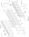
- FIG. 3 is an exploded perspective view of the battery module according to an embodiment.
- FIG. 4 is a perspective view of a battery cell fixation member according to an embodiment.
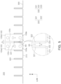
- FIG. 5 is a top view of a battery pack combined with the elastic plate according to an embodiment.
- a battery module 200 may include the plurality of battery cells 100, an end plate 210, and an elastic plate 300.
- the description of the battery cell 100 in FIG. 1 may be applied to the battery cell 100 in FIGS. 2 , 3 and/or 5.
- the plurality of battery cells 100 may be arranged to be parallel to each other.
- the plurality of battery cells 100 may be arranged in a first direction (e.g., +Y-axis direction).
- the plurality of battery cells 100 may include a first battery cell 100a and a second battery cell 100b close to the first battery cell 100a.
- the second battery cell 100b may be one of the battery cells 100 closest to the first battery cell 100a among the plurality of battery cells 100.
- the plurality of battery cells 100 may be arranged to be spaced from each other.
- the first battery cell 100a may be spaced apart from the second battery cell 100b by a specified gap G.
- the plurality of battery cells 100 may be staggered with each other.
- the battery cells 100 close to each other may be arranged so that the first terminal 131 and the second terminal 132 face different directions.
- the number of plurality of battery cells 100 shown in the present disclosure is exemplary.
- the end plate 210 may form at least a portion of an exterior of the battery module 200.
- the end plate 210 may cover a portion of the battery cell 100 disposed at the outermost portion of the plurality of battery cells 100.
- the plurality of battery cells 100 may include a third battery cell 100c forming one end in the first direction (e.g., +Y-direction) and a fourth battery cell 100d forming the other end in the second direction (e.g., -Y-direction) which is opposite to the first direction (+Y-direction).
- the end plate 210 may include a first end cover 211 covering at least a portion of the third battery cell 100c, and a second end cover 212 covering at least a portion of the fourth battery cell 100d.
- the first end cover 211 may be referred to as a front cover
- the second end cover 212 may be referred to as a rear cover.
- the end plate 210 may provide pressure (e.g., surface pressure) to the battery cell 100.
- the end plate 210 may be in contact with the third side 120c of the battery cell 100, and provide the pressure to the third side 120c.
- the first end cover 211 may provide the pressure to the third battery cell 100c in the second direction (-Y-direction).
- the second cover 212 may provide pressure to the fourth battery cell 100d in the first direction (+Y-direction). Swelling of the battery cell 100 may be reduced by the pressure provided by the end plate 210 to the battery cell 100.
- the battery module 200 may include the insulating plate (not shown) disposed between the end plate 210 and the battery cell 100.
- the elastic plate 300 may form at least a portion of the exterior of the battery module 200, and accommodate the plurality of battery cells 100, together with the end plate 210.
- the end plate 210 and the elastic plate 300 may surround the plurality of battery cells 100.
- the plurality of battery cells 100 may be provided with the pressure from all the sides by the end plate 210 and the elastic plate 300.
- the plurality of battery cells 100 may receive the pressure in the first direction (+Y-direction) and the second direction (-Y-direction) by the end plate 210, and receive the pressure in a third direction (+X-direction) and a fourth direction (-X-direction) by the elastic plate 300.
- the end plate 210 and the elastic plate 300 combined with the end plate 210 may be referred to as a battery cell fixation member 240. Positions of the plurality of battery cells 100 may be maintained or fixed by the end plate 210 and the elastic plate 300.
- the elastic plate 300 of the battery cell fixation member 240 may accommodate the battery cells 100.
- a cover part 310 and a buffer portion 320 may form an accommodation space AS surrounding the battery cell 100.
- the accommodate space AS may be an empty space at least partially surrounded by the cover part 310 and the buffer portion 320.
- the battery cell 100 may be inserted into the accommodation space AS, and the sides of the case 120 (e.g., first side 120a, second side 120b, and the third side 120c in FIG. 1 ) may be surrounded by the cover part 310 and the buffer portion 320.
- the accommodation space AS may be formed by a first elastic plate 300a and a second elastic plate 300b.
- a plurality of buffer portions 320 may be spaced apart from each other to have the accommodation space AS.
- Each of the plurality of battery cells 100 may be disposed between the plurality of buffer portions 320 close to each other.
- the positions of the plurality of battery cells 100 may be maintained by an elastic force of the end plate 210 and/or the plurality of buffer portions 320 and a frictional force between the case 120 and the buffer portion 320.
- the accommodation space AS may be formed by the end plate 210 and the elastic plate 300.
- the battery cell e.g., third battery cell 100c or fourth battery cell 100d
- disposed at the outermost portion of the plurality of battery cells 100 may be disposed in the accommodation space AS formed by the end plate 210 and the elastic plate 300.
- the elastic plate 300 may at least partially cover the sides of the plurality of battery cells 100.
- the elastic plate 300 may include a cover part 310 covering the sides of the plurality of battery cells 100.
- the cover part 310 may be in contact with the first side 120a or second side 120b of the battery cell 100.
- the cover part 310 of the first elastic plate 300a may be in contact with the first side 120a of the battery cell 100, and provide the pressure in the third direction (+X-direction) to the first side 120a.
- the cover part 310 of the second elastic plate 300b may be in contact with the second side 120b of the battery cell 100, and provide the pressure in the fourth direction (-X-direction) to the second side 120b.
- the plurality of cover parts 310 may be provided.
- the cover part 310 may be a portion of the elastic plate 300 connecting the plurality of buffer portions 320 to each other.
- the number of cover parts 310 may be proportional to the number of battery cells 100 of the battery module 200.
- the battery module 200 may include 2N cover parts 310.
- the elastic plate 300 may absorb at least a portion of a thickness change caused by the swelling of the plurality of battery cells 100.
- the elastic plate 300 may include the buffer portion 320 disposed between at least some of the plurality of battery cells 100.
- the buffer portion 320 may be contracted or compressed based on the thickness change in the battery cell 100.
- the buffer portion 320 may be deformed to thus prevent damage to the battery module 200.
- the buffer portion 320 may be referred to as a leaf spring, a fin, or a flat clip.
- the buffer portion 320 may be disposed between the battery cells 100 close to each other among the plurality of battery cells 100.
- the plurality of battery cells 100 may include the first battery cell 100a and the second battery cell 100b spaced apart from the first battery cell 100a.
- the first battery cell 100a may be a random battery cell among the plurality of battery cells 100
- the second battery cell 100b may be the battery cell 100 closest to the first battery cell 100a among the plurality of battery cells 100.
- the buffer portion 320 may be disposed in the gap G between the first battery cell 100a and the second battery cell 100b.
- the number of buffer portions 320 may be proportional to the number of battery cells 100 of the battery module 200.
- the battery module 200 in an embodiment that includes N battery cells 100, the battery module 200 may include 2(N-1) buffer portions 320.
- the number of band members 320 may be selectively designed.
- FIGS. 2 , 3 , and/or 4 show that the battery module 200 includes the buffer portion 320 disposed between the plurality of battery cells 100, and a structure of the battery module 200 is not limited thereto.
- at least some (e.g., two) of the battery cells 100 may be in contact with each other, and the buffer portion 320 may be disposed between every two of the battery cells 100.
- the buffer portion 320 may include a first support region 321 facing the first battery cell 100a and a second support region 322 facing the second battery cell 100b.
- the first support region 321 may be in contact with a portion of the third side 120c of the first battery cell 100a.
- the second support region 322 may be in contact with a portion of the third side 120c of the second battery cell 100b.
- the first support region 321 may be spaced apart from the second support region 322.
- the elastic plate 300 may include a buffer space BS disposed between the first support region 321 and the second support region 322.
- the buffer space BS of the buffer portion 320 may be deformed based on the swelling of the battery cell 100.
- a width d of the buffer space BS may be reduced when the battery cell 100 is swollen.
- the buffer space BS may reduce length deformation of the battery module 200 (e.g., its length in the Y-axis direction).
- the elastic plate 300 may absorb the swelling of the battery cell 100 and function as a damper by using a deformed shape of the buffer space BS.
- the width d of the buffer space BS may be shorter than the gap G between the battery cells 100.
- the elastic plate 300 may provide a flow path for cooling and/or heat dissipation of the battery cell 100.
- the buffer space BS of the elastic plate 300 may provide a path for air to flow.
- the battery cell 100 may dissipate heat by air flowing through the buffer space BS.
- the buffer portion 320 of the elastic plate 300 may increase a contact area between the battery module 200 and air.
- the elastic plate 300 may be made of a material for the heat dissipation.
- the elastic plate 300 may be made of an elastic material.
- the elastic plate 300 may include the stainless steel.
- the material of the elastic plate 300 is not limited to the stainless steel, as long as the elastic plate 300 uses a material that may provide elasticity and heat dissipation effects.
- the elastic plate 300 may include a heat treated material to improve its elasticity and shape memory.
- the elastic plate 300 may include the first elastic plate 300a and the second elastic plate 300b spaced apart from the first elastic plate 300a.
- the cover part 310 may include a first cover part 310a forming a portion of the first elastic plate 300a and a second cover part 310b forming a portion of the second elastic plate 300b.
- the buffer portion 320 may include a first buffer portion 320a forming a portion of the first elastic plate 300a and a second buffer portion 320b forming a portion of the second elastic plate 300b.
- the first elastic plate 300a may include the first cover part 310a covering one side of each of the plurality of battery cells 100 and the first buffer portion 320a extending from the first cover part 310a and disposed between at least some of the plurality of battery cells 100.
- the second elastic plate 300b may include the second cover part 310b covering the other side of each of the plurality of battery cells 100 and the second buffer portion 320b extending from the second cover part 310b and disposed between at least some of the
- the third side 120c of the battery cell 100 may be in contact with the buffer portion 320.
- the buffer portion 320 may extend to the center portion of the battery cell 100.
- an edge portion 121 of the third side 120c may be in contact with the first buffer portion 320a or the second buffer portion 320b.
- At least a portion of a center portion 122 of the third side 120c may be in contact with the first buffer portion 320a and the second buffer portion 320b.
- the center portion 122 having a large amount of change due to the swelling of the battery cell 100 may be in contact with the two buffer portions (e.g., first buffer portion 320a and second buffer portion 320b), thereby increasing buffering and/or damper effects of the elastic plate 300.
- the respective components of the elastic plates 300 may be integrated with each other.
- the buffer portion 320 may extend from the cover part 310.
- the buffer portion 320 may substantially have a "U" shape, and each of two ends of the buffer portion 320 may be connected to the cover part 310.
- the elastic plate 300 may be the leaf spring that is partially bent.
- the elastic plate 300 may include a plurality of bent regions 330.
- the elastic plate 300 may include a first bent region 331 connecting the first support region 321 and the second support region 322 to each other.
- the elastic plate 300 may include a second bent region 332 connecting the first support region 321 and the cover part 310 to each other and a third bent region 333 connecting the second support region 322 and the cover part 310 to each other.
- the bent region 330 may increase a deformation rate of the elastic plate 300.
- a distance between the first support region 321 and the second support region 322 may be changed, and the elastic plate 300 may function as a damper for at least partially absorbing the deformation of the battery cell 100.
- the elastic plate 300 may be referred to as a flat stair spring.
- the elastic plate 300 may provide the elastic force to the first end cover 211 and the second end cover 212 in a direction in which the first end cover 211 and the second end cover 212 are close to each other.
- two ends of the elastic plate 300 e.g., cover part 310 disposed on the outermost portions
- the elastic plate 300 may be contracted, and the first end cover 211 and the second end cover 212 may each provide the elastic force in a direction for pressing the battery cell 100.
- the battery module 200 may include a bus bar assembly (not shown).
- the bus bar assembly may be electrically connected to the terminals 131 and 132 of the battery cell 100.
- the bus bar assembly may include at least one connection terminal (not shown) for its electrical connection to the outside.
- the connection terminal may be electrically connected to a bus bar.
- the terminals 131 and 132 of the battery cell 100 may be electrically connected to the outside of the battery module 200 through the bus bar assembly.
- FIG. 6 is a perspective view of the battery pack according to an embodiment.
- a battery pack 400 may include the plurality of battery modules 200 and a pack frame 410 accommodating the plurality of battery modules 200.
- the description of the battery module 200 described above with reference to FIGS. 2 and 3 may be applied to the battery module 200 in FIG. 6 .
- a shape of the battery module 200 is partially omitted in FIG. 6 .
- the pack frame 410 may include a partition 414 crossing at least some of the plurality of battery modules 200.
- the accommodation space of the pack frame 410 may be partitioned into a plurality of spaces by the partition 414.
- the partition 414 may be installed across the accommodation space to reinforce rigidity of the pack frame 410.
- at least some of the plurality of partitions 414 may include venting holes for guiding paths of gas and/or flame occurring in the battery module 200.
- the partition 414 may face at least a portion of the elastic plate (e.g., elastic plate 300 in FIG. 2 ).
- a structure of the pack frame 410 in the present disclosure is exemplary, and may depend on a design of the battery pack 400.
- the battery pack 400 may include a duct member 460.
- a flow space where the gas and/or flame discharged from the battery module 200 flows may be formed in the duct member 460.
- the duct member 460 may be disposed in the pack frame 410.
- the flow space of the duct member 460 may be connected to the venting hole in the partition 414.
- the gas and/or flame occurring in the battery cell of the battery module 200 e.g., battery cell 100 in FIG. 1
- the gas and/or flame occurring in the battery cell of the battery module 200 may pass through the venting hole formed in the partition 414 and the flow space of the duct member 460 to thus be transmitted externally from the battery pack 400.
- the battery pack 400 may include a battery control unit 490 controlling the battery module 200.
- the battery control unit 490 may be disposed in the pack frame 410.
- the battery control unit 490 may include a battery management system (BMS).
- BMS battery management system
- a configuration of the battery control unit 490 is known in various forms, and a detailed description is thus omitted.
- the battery control unit 490 may be referred to as a processor.
Landscapes
- Chemical & Material Sciences (AREA)
- Chemical Kinetics & Catalysis (AREA)
- Electrochemistry (AREA)
- General Chemical & Material Sciences (AREA)
- Engineering & Computer Science (AREA)
- Manufacturing & Machinery (AREA)
- Battery Mounting, Suspending (AREA)
Abstract
Description
- The disclosure and implementations disclosed in this patent document generally relate to a battery module comprising an elastic plate and a battery pack comprising the same.
- Unlike a primary battery, a secondary battery may be charged and discharged, and thus may be applied to devices within various fields such as a digital camera, a mobile phone, a laptop personal computer (PC), a hybrid vehicle, an electric vehicle, and an energy storage system (ESS). The secondary battery may be a lithium-ion battery, a nickel-cadmium battery, a nickel-metal hydride battery, or a nickel-hydrogen battery.
- The secondary battery may be manufactured by a flexible pouch-type battery cell or a rigid prismatic or cylindrical can-type battery cell. The plurality of battery cells may be formed as a stacked cell assembly.
- The cell assembly may be disposed in a case to form a battery module, and the plurality of battery modules may be disposed in a pack housing to form a battery pack. The battery pack may be used in a variety of structures such as a vehicle or an energy storage system.
- A battery module may include a plurality of battery cells. However, such battery cells may be swollen due to overcharging, external impact, or aging. The size and shape of the battery module may be deformed and damaged due to the swelling of the battery cells.
- A compression pad disposed between the battery cells may be used to absorb swelling force of the battery cell. However, the compression pad may cause increased production costs and manufacturing time of the battery module.
- The present disclosure may be implemented in some embodiments to provide a battery module modified based on swelling of a battery cell to include an elastic plate capable of absorbing an impact, and a battery pack comprising the same.
- The present disclosure may be implemented in some embodiments to provide a battery module requiring no compression pad to thus achieve a reduced production cost, and a battery pack comprising the same.
- The present disclosure may be implemented in some embodiments to provide a battery module having a reduced assembly time by excluding an attachment process of a compression pad to a battery cell, and a battery pack comprising the same.
- The battery module and the battery pack in the present disclosure may be widely applied in a green technology field such as to an electric vehicle, a battery charging station, and other solar power generation and wind power generation, using the battery. In addition, the battery module and the battery pack in the present disclosure may suppress air pollution and greenhouse gas emissions to thus be used in an eco-friendly electric vehicle, a hybrid vehicle, or the like for ameliorating a climate change.
- In some embodiments of the present disclosure, a battery module includes: a plurality of battery cells; a plurality of end plates respectively disposed on both sides of the plurality of battery cells; and an elastic plate connected to the plurality of end plates, wherein the elastic plate includes a cover part covering sides of the plurality of battery cells, and a buffer portion extending from the cover part, and disposed between at least some of the plurality of battery cells.
- The plurality of battery cells may include a first battery cell and a second battery cell spaced apart from the first battery cell, and the buffer portion may include a first support region facing the first battery cell, a second support region facing the second battery cell, and a first bent region connecting the first support region and the second support region to each other.
- The elastic plate may include a second bent region connecting the first support region and the cover part to each other, and a third bent region connecting the second support region and the cover part to each other.
- The first support region may be spaced apart from the second support region, and the elastic plate may include a buffer space disposed between the first support region and the second support region, and configured to be deformed based on swelling of the battery cell.
- The buffer portion may be in contact with at least some of the plurality of battery cells, and the buffer space may provide a path for air to flow.
- The end plate may include a protrusion having a hook, and the cover part may include a groove configured to accommodate the hook.
- Each of the plurality of battery cells may include an electrode assembly, a case accommodating the electrode assembly, and a cap assembly connected to the case, and the case may include a first side, a second side opposite to the first side, and a third side extending from the first side to the second side and facing the buffer portion.
- The elastic plate may include a first elastic plate and a second elastic plate spaced apart from the first elastic plate.
- The first elastic plate may include a first cover part facing the first side, and a first buffer portion extending from the first cover part and disposed between the plurality of battery cells, the second elastic plate may include a second cover part facing the second side, and a second buffer portion extending from the second cover part and disposed between the plurality of battery cells, a portion of the first buffer portion may face a portion of the second buffer portion, and the third side may face the first buffer portion and the second buffer portion.
- The third side may include an edge portion and a center portion surrounded by the edge portion, the edge portion may be in contact with the first buffer portion or the second buffer portion, and at least a portion of the center portion may be in contact with the first buffer portion and the second buffer portion.
- The plurality of battery cells may include a third battery cell forming one end in a first direction and a fourth battery cell forming the other end in a second direction opposite to the first direction, and the end plate may include a first end cover configured to provide pressure to the third battery cell in the second direction, and a second end cover configured to provide pressure to the fourth battery cell in the first direction.
- Two ends of the elastic plate may be respectively connected to the first end cover and the second end cover, and an elastic force may be provided to the first end cover and the second end cover in a direction in which the first end cover and the second end cover are close to each other.
- The cover part and the buffer portion may form an accommodation space surrounding at least some of the plurality of battery cells.
- The elastic plate may include stainless steel.
- In some embodiments of the present disclosure, a battery pack includes: a plurality of battery modules; and a pack frame accommodating the plurality of battery modules, wherein each of the plurality of battery modules includes a plurality of battery cells, an end plate disposed on each of both sides of the plurality of battery cells, and an elastic plate connected to the end plate, and the elastic plate includes a cover part covering sides of the plurality of battery cells, and a buffer portion extending from the cover part, and disposed between at least some of the plurality of battery cells.
-
-
FIG. 1 is a perspective view of a battery cell according to an embodiment. -
FIG. 2 is a perspective view of a battery module according to an embodiment. -
FIG. 3 is an exploded perspective view of the battery module according to an embodiment. -
FIG. 4 is a perspective view of a battery cell fixation member according to an embodiment. -
FIG. 5 is a top view of a battery pack combined with the elastic plate according to an embodiment. -
FIG. 6 is a perspective view of the battery pack according to an embodiment. - Hereinafter, embodiments of the present disclosure are described in detail with reference to the accompanying drawings. However, the embodiments are only exemplary, and the present disclosure is not limited to the specific embodiments exemplary described.
- Terms or words used in the specification and claims described below are not to be construed as limited to their general or dictionary meanings. The terms or words will be interpreted as meanings and concepts consistent with the spirit of the present disclosure based on a principle that inventors may appropriately define the concepts of the terms in order to explain their inventions in the best mode.
- Therefore, the embodiments described in the specification and the configurations shown in the drawings only exemplify the some embodiments, and do not represent all of the spirits of the present disclosure. Therefore, the present disclosure should be construed as including all the various equivalents and substitutions included in the spirit and scope of the present disclosure at the time of filing this application.
- The description omits details of the known function and structure, which may obscure the gist of the present disclosure. Further, some components shown in the accompanying drawings are exaggerated, omitted, or schematically shown, and the size of each component does not exactly reflect its real size.
-
FIG. 1 is a perspective view of a battery cell according to an embodiment. - Referring to
FIG. 1 , abattery cell 100 may include acase 120 and acap assembly 130. Thebattery cell 100 may be a secondary battery. For example, thebattery cell 100 may be a lithium ion battery, and is not limited thereto. For example, thebattery cell 100 may be a nickel-cadmium electric battery, a nickel-metal hydride battery, or a nickel-hydrogen battery, which may be charged and discharged. - The
case 120 may accommodate an electrode assembly (not shown) and an electrolyte. The electrode assembly 110 may include a cathode plate, an anode plate, and a separator. The separator may prevent contact between the cathode plate and the anode plate. Those skilled in the art may understand that the electrode assembly may be manufactured using a variety of methods. According to example embodiments, the electrode assembly may be formed by repeatedly disposing the cathode, the anode, and the separator. In some embodiments, the electrode assembly may be a winding type, a stacking type, a Z-fold type, or a stack-folding type. - The
case 120 may form at least a portion of an exterior of thebattery cell 100. Thecase 120 may substantially have a shape of a rectangular parallelepiped, at least a portion of which is open. For example, thecase 120 may include afirst side 120a, asecond side 120b opposite to thefirst side 120a, and athird side 120c extending from thefirst side 120a to thesecond side 120b, and abottom side 120d. Thethird side 120c may be substantially perpendicular to thefirst side 120a or thesecond side 120b. Thebottom side 120d may be substantially perpendicular to thefirst side 120a, thesecond side 120b, or thethird side 120c. The area or width of thethird side 120c may be larger than the area or width of thefirst side 120a or that of thesecond side 120b. In an embodiment, thefirst side 120a or thesecond side 120b may be referred to as a narrow side, and thethird side 120c may be referred to as wide side. In an embodiment, thecase 120 may include aluminum and/or stainless steel. In an embodiment, thecase 120 may be referred to as a can or a housing. - The
cap assembly 130 may be combined with thecase 120. For example, thecap assembly 130 may be joined and connected to one end of the case. Thecap assembly 130 may accommodate the electrode assembly and the electrolyte, together with thecase 120. - The
cap assembly 130 may include a plurality of components. - The
cap assembly 130 may include acap plate 135, which is combined with thecase 120 to form a portion of the exterior of thebattery cell 100. - The
cap assembly 130 may includeterminals cap assembly 130 may include the first terminal 131 (e.g., cathode terminal) connected to the cathode plate of the electrode assembly and the second terminal 132 (e.g., anode terminal) connected to the anode plate of the electrode assembly. Thefirst terminal 131 and thesecond terminal 132 may be exposed externally from thebattery cell 100 through a hole formed in thecap plate 135. - The
cap assembly 130 may include a ventingpart 133 providing a path for discharging a gas occurring in the electrode assembly externally from thecase 120. The ventingpart 133 may include a notch that is broken at a specified pressure or above. The ventingpart 133 may be formed at thecap plate 135. - The
cap assembly 130 may include anelectrolyte sealing member 134. Theelectrolyte sealing member 134 may seal an electrolyte injection port formed at thecap plate 135. Theelectrolyte sealing member 134 may prevent the electrolyte from leaking out of thebattery cell 100. Theelectrolyte sealing member 134 may include an electrolyte cap welded to thecap plate 135 and/or a locking ball inserted into the electrolyte injection port of thecap plate 135. - The components of the
cap assembly 130 described above are only an embodiment. Accordingly, some of the components of thecap assembly 130 may be omitted or other components not described herein may be added. For example, thecap assembly 130 may include a current collector, an insulating plate, a resistance plate, a rivet terminal, and/or a gasket. -
FIG. 2 is a perspective view of a battery module according to an embodiment.FIG. 3 is an exploded perspective view of the battery module according to an embodiment.FIG. 4 is a perspective view of a battery cell fixation member according to an embodiment.FIG. 5 is a top view of a battery pack combined with the elastic plate according to an embodiment. - Referring to
FIGS. 2 ,3 ,4 , and/or 5, abattery module 200 may include the plurality ofbattery cells 100, anend plate 210, and anelastic plate 300. The description of thebattery cell 100 inFIG. 1 may be applied to thebattery cell 100 inFIGS. 2 ,3 and/or 5. - The plurality of
battery cells 100 may be arranged to be parallel to each other. The plurality ofbattery cells 100 may be arranged in a first direction (e.g., +Y-axis direction). In an embodiment, the plurality ofbattery cells 100 may include afirst battery cell 100a and asecond battery cell 100b close to thefirst battery cell 100a. Thesecond battery cell 100b may be one of thebattery cells 100 closest to thefirst battery cell 100a among the plurality ofbattery cells 100. The plurality ofbattery cells 100 may be arranged to be spaced from each other. For example, thefirst battery cell 100a may be spaced apart from thesecond battery cell 100b by a specified gap G. In an embodiment, the plurality ofbattery cells 100 may be staggered with each other. For example, thebattery cells 100 close to each other may be arranged so that thefirst terminal 131 and thesecond terminal 132 face different directions. The number of plurality ofbattery cells 100 shown in the present disclosure is exemplary. - The
end plate 210 may form at least a portion of an exterior of thebattery module 200. Theend plate 210 may cover a portion of thebattery cell 100 disposed at the outermost portion of the plurality ofbattery cells 100. For example, the plurality ofbattery cells 100 may include athird battery cell 100c forming one end in the first direction (e.g., +Y-direction) and afourth battery cell 100d forming the other end in the second direction (e.g., -Y-direction) which is opposite to the first direction (+Y-direction). Theend plate 210 may include afirst end cover 211 covering at least a portion of thethird battery cell 100c, and asecond end cover 212 covering at least a portion of thefourth battery cell 100d. In an embodiment, thefirst end cover 211 may be referred to as a front cover, and thesecond end cover 212 may be referred to as a rear cover. - The
end plate 210 may provide pressure (e.g., surface pressure) to thebattery cell 100. For example, theend plate 210 may be in contact with thethird side 120c of thebattery cell 100, and provide the pressure to thethird side 120c. In an embodiment, thefirst end cover 211 may provide the pressure to thethird battery cell 100c in the second direction (-Y-direction). Thesecond cover 212 may provide pressure to thefourth battery cell 100d in the first direction (+Y-direction). Swelling of thebattery cell 100 may be reduced by the pressure provided by theend plate 210 to thebattery cell 100. - In an embodiment (not shown), the
battery module 200 may include the insulating plate (not shown) disposed between theend plate 210 and thebattery cell 100. - The
elastic plate 300 may form at least a portion of the exterior of thebattery module 200, and accommodate the plurality ofbattery cells 100, together with theend plate 210. For example, theend plate 210 and theelastic plate 300 may surround the plurality ofbattery cells 100. For example, the plurality ofbattery cells 100 may be provided with the pressure from all the sides by theend plate 210 and theelastic plate 300. In an embodiment, the plurality ofbattery cells 100 may receive the pressure in the first direction (+Y-direction) and the second direction (-Y-direction) by theend plate 210, and receive the pressure in a third direction (+X-direction) and a fourth direction (-X-direction) by theelastic plate 300. - The
end plate 210 and theelastic plate 300 combined with theend plate 210 may be referred to as a batterycell fixation member 240. Positions of the plurality ofbattery cells 100 may be maintained or fixed by theend plate 210 and theelastic plate 300. For example, theelastic plate 300 of the batterycell fixation member 240 may accommodate thebattery cells 100. For example, acover part 310 and abuffer portion 320 may form an accommodation space AS surrounding thebattery cell 100. The accommodate space AS may be an empty space at least partially surrounded by thecover part 310 and thebuffer portion 320. - The
battery cell 100 may be inserted into the accommodation space AS, and the sides of the case 120 (e.g.,first side 120a,second side 120b, and thethird side 120c inFIG. 1 ) may be surrounded by thecover part 310 and thebuffer portion 320. The accommodation space AS may be formed by a firstelastic plate 300a and a secondelastic plate 300b. - A plurality of
buffer portions 320 may be spaced apart from each other to have the accommodation space AS. Each of the plurality ofbattery cells 100 may be disposed between the plurality ofbuffer portions 320 close to each other. The positions of the plurality ofbattery cells 100 may be maintained by an elastic force of theend plate 210 and/or the plurality ofbuffer portions 320 and a frictional force between thecase 120 and thebuffer portion 320. In an embodiment, the accommodation space AS may be formed by theend plate 210 and theelastic plate 300. The battery cell (e.g.,third battery cell 100c orfourth battery cell 100d) disposed at the outermost portion of the plurality ofbattery cells 100 may be disposed in the accommodation space AS formed by theend plate 210 and theelastic plate 300. - The
elastic plate 300 may at least partially cover the sides of the plurality ofbattery cells 100. For example, theelastic plate 300 may include acover part 310 covering the sides of the plurality ofbattery cells 100. Thecover part 310 may be in contact with thefirst side 120a orsecond side 120b of thebattery cell 100. Thecover part 310 of the firstelastic plate 300a may be in contact with thefirst side 120a of thebattery cell 100, and provide the pressure in the third direction (+X-direction) to thefirst side 120a. Thecover part 310 of the secondelastic plate 300b may be in contact with thesecond side 120b of thebattery cell 100, and provide the pressure in the fourth direction (-X-direction) to thesecond side 120b. The plurality ofcover parts 310 may be provided. For example, thecover part 310 may be a portion of theelastic plate 300 connecting the plurality ofbuffer portions 320 to each other. The number ofcover parts 310 may be proportional to the number ofbattery cells 100 of thebattery module 200. For example, in thebattery module 200 includingN battery cells 100, thebattery module 200 may include 2N coverparts 310. - The
elastic plate 300 may absorb at least a portion of a thickness change caused by the swelling of the plurality ofbattery cells 100. For example, theelastic plate 300 may include thebuffer portion 320 disposed between at least some of the plurality ofbattery cells 100. - The
buffer portion 320 may be contracted or compressed based on the thickness change in thebattery cell 100. Thebuffer portion 320 may be deformed to thus prevent damage to thebattery module 200. In an embodiment, thebuffer portion 320 may be referred to as a leaf spring, a fin, or a flat clip. In an embodiment, thebuffer portion 320 may be disposed between thebattery cells 100 close to each other among the plurality ofbattery cells 100. For example, the plurality ofbattery cells 100 may include thefirst battery cell 100a and thesecond battery cell 100b spaced apart from thefirst battery cell 100a. Thefirst battery cell 100a may be a random battery cell among the plurality ofbattery cells 100, and thesecond battery cell 100b may be thebattery cell 100 closest to thefirst battery cell 100a among the plurality ofbattery cells 100. Thebuffer portion 320 may be disposed in the gap G between thefirst battery cell 100a and thesecond battery cell 100b. - The number of
buffer portions 320 may be proportional to the number ofbattery cells 100 of thebattery module 200. For example, in thebattery module 200 in an embodiment that includesN battery cells 100, thebattery module 200 may include 2(N-1)buffer portions 320. - The number of
band members 320 may be selectively designed.FIGS. 2 ,3 , and/or 4 show that thebattery module 200 includes thebuffer portion 320 disposed between the plurality ofbattery cells 100, and a structure of thebattery module 200 is not limited thereto. For example, in an embodiment (not shown), at least some (e.g., two) of thebattery cells 100 may be in contact with each other, and thebuffer portion 320 may be disposed between every two of thebattery cells 100. - The
buffer portion 320 may include afirst support region 321 facing thefirst battery cell 100a and asecond support region 322 facing thesecond battery cell 100b. Thefirst support region 321 may be in contact with a portion of thethird side 120c of thefirst battery cell 100a. Thesecond support region 322 may be in contact with a portion of thethird side 120c of thesecond battery cell 100b. Thefirst support region 321 may be spaced apart from thesecond support region 322. For example, theelastic plate 300 may include a buffer space BS disposed between thefirst support region 321 and thesecond support region 322. The buffer space BS of thebuffer portion 320 may be deformed based on the swelling of thebattery cell 100. For example, a width d of the buffer space BS may be reduced when thebattery cell 100 is swollen. The buffer space BS may reduce length deformation of the battery module 200 (e.g., its length in the Y-axis direction). Theelastic plate 300 may absorb the swelling of thebattery cell 100 and function as a damper by using a deformed shape of the buffer space BS. The width d of the buffer space BS may be shorter than the gap G between thebattery cells 100. - In an embodiment, the
elastic plate 300 may provide a flow path for cooling and/or heat dissipation of thebattery cell 100. In an embodiment, the buffer space BS of theelastic plate 300 may provide a path for air to flow. Thebattery cell 100 may dissipate heat by air flowing through the buffer space BS. For example, thebuffer portion 320 of theelastic plate 300 may increase a contact area between thebattery module 200 and air. In an embodiment, theelastic plate 300 may be made of a material for the heat dissipation. Theelastic plate 300 may be made of an elastic material. For example, theelastic plate 300 may include the stainless steel. However, the material of theelastic plate 300 is not limited to the stainless steel, as long as theelastic plate 300 uses a material that may provide elasticity and heat dissipation effects. In an embodiment, theelastic plate 300 may include a heat treated material to improve its elasticity and shape memory. - The
elastic plate 300 may include the firstelastic plate 300a and the secondelastic plate 300b spaced apart from the firstelastic plate 300a. Thecover part 310 may include afirst cover part 310a forming a portion of the firstelastic plate 300a and asecond cover part 310b forming a portion of the secondelastic plate 300b. Thebuffer portion 320 may include afirst buffer portion 320a forming a portion of the firstelastic plate 300a and asecond buffer portion 320b forming a portion of the secondelastic plate 300b. The firstelastic plate 300a may include thefirst cover part 310a covering one side of each of the plurality ofbattery cells 100 and thefirst buffer portion 320a extending from thefirst cover part 310a and disposed between at least some of the plurality ofbattery cells 100. The secondelastic plate 300b may include thesecond cover part 310b covering the other side of each of the plurality ofbattery cells 100 and thesecond buffer portion 320b extending from thesecond cover part 310b and disposed between at least some of the plurality ofbattery cells 100. - The
third side 120c of thebattery cell 100 may be in contact with thebuffer portion 320. Thebuffer portion 320 may extend to the center portion of thebattery cell 100. For example, an edge portion 121 of thethird side 120c may be in contact with thefirst buffer portion 320a or thesecond buffer portion 320b. At least a portion of a center portion 122 of thethird side 120c may be in contact with thefirst buffer portion 320a and thesecond buffer portion 320b. The center portion 122 having a large amount of change due to the swelling of thebattery cell 100 may be in contact with the two buffer portions (e.g.,first buffer portion 320a andsecond buffer portion 320b), thereby increasing buffering and/or damper effects of theelastic plate 300. - The respective components of the
elastic plates 300 may be integrated with each other. For example, thebuffer portion 320 may extend from thecover part 310. In an embodiment, thebuffer portion 320 may substantially have a "U" shape, and each of two ends of thebuffer portion 320 may be connected to thecover part 310. Theelastic plate 300 may be the leaf spring that is partially bent. Theelastic plate 300 may include a plurality ofbent regions 330. For example, theelastic plate 300 may include a firstbent region 331 connecting thefirst support region 321 and thesecond support region 322 to each other. Theelastic plate 300 may include a secondbent region 332 connecting thefirst support region 321 and thecover part 310 to each other and a thirdbent region 333 connecting thesecond support region 322 and thecover part 310 to each other. Thebent region 330 may increase a deformation rate of theelastic plate 300. For example, as curvatures of the firstbent region 331, the secondbent region 332, and/or the thirdbent region 333 are changed, a distance between thefirst support region 321 and thesecond support region 322 may be changed, and theelastic plate 300 may function as a damper for at least partially absorbing the deformation of thebattery cell 100. In an embodiment, theelastic plate 300 may be referred to as a flat stair spring. - The
elastic plate 300 may be combined with theend plate 210. For example, theend plate 210 in an embodiment may include at least oneprotrusion 219 having a hook, and theelastic plate 300 may include at least onecombination groove 319 for accommodating theprotrusion 219. In an embodiment (not shown), theelastic plate 300 may include at least one protrusion having a hook, and theend plate 210 may include a combination groove for accommodating at least one protrusion. In an embodiment (not shown), theend plate 210 and theelastic plate 300 may be combined with each other by at least one fastening member (e.g., bolt) (not shown). - The
elastic plate 300 may provide the elastic force to thefirst end cover 211 and thesecond end cover 212 in a direction in which thefirst end cover 211 and thesecond end cover 212 are close to each other. For example, two ends of the elastic plate 300 (e.g., coverpart 310 disposed on the outermost portions) may respectively be connected to thefirst end cover 211 or thesecond end cover 212. Theelastic plate 300 may be contracted, and thefirst end cover 211 and thesecond end cover 212 may each provide the elastic force in a direction for pressing thebattery cell 100. - The
battery module 200 may include a bus bar assembly (not shown). The bus bar assembly may be electrically connected to theterminals battery cell 100. - The bus bar assembly may include at least one connection terminal (not shown) for its electrical connection to the outside. The connection terminal may be electrically connected to a bus bar. The
terminals battery cell 100 may be electrically connected to the outside of thebattery module 200 through the bus bar assembly. -
FIG. 6 is a perspective view of the battery pack according to an embodiment. - Referring to
FIG. 6 , abattery pack 400 may include the plurality ofbattery modules 200 and a pack frame 410 accommodating the plurality ofbattery modules 200. The description of thebattery module 200 described above with reference toFIGS. 2 and3 may be applied to thebattery module 200 inFIG. 6 . However, for convenience of explanation, a shape of thebattery module 200 is partially omitted inFIG. 6 . - The pack frame 410 may accommodate components of the battery pack 400 (e.g., battery module 200). The pack frame 410 may include a
bottom member 411 supporting thebattery module 200, apack cover 412 covering thebattery module 200, and apack side wall 413 connecting thebottom member 411 and thepack cover 412. Thebottom member 411 may support thebottom side 120d of thebattery cell 100. Thepack side wall 413 may face at least a portion of the elastic plate (e.g.,elastic plate 300 inFIG. 2 ). - The pack frame 410 may include a
partition 414 crossing at least some of the plurality ofbattery modules 200. For example, the accommodation space of the pack frame 410 may be partitioned into a plurality of spaces by thepartition 414. Thepartition 414 may be installed across the accommodation space to reinforce rigidity of the pack frame 410. In an embodiment, at least some of the plurality ofpartitions 414 may include venting holes for guiding paths of gas and/or flame occurring in thebattery module 200. Thepartition 414 may face at least a portion of the elastic plate (e.g.,elastic plate 300 inFIG. 2 ). A structure of the pack frame 410 in the present disclosure is exemplary, and may depend on a design of thebattery pack 400. - In an embodiment, the
battery pack 400 may include aduct member 460. A flow space where the gas and/or flame discharged from thebattery module 200 flows may be formed in theduct member 460. Theduct member 460 may be disposed in the pack frame 410. The flow space of theduct member 460 may be connected to the venting hole in thepartition 414. For example, the gas and/or flame occurring in the battery cell of the battery module 200 (e.g.,battery cell 100 inFIG. 1 ) may pass through the venting hole formed in thepartition 414 and the flow space of theduct member 460 to thus be transmitted externally from thebattery pack 400. - The
battery pack 400 may include abattery control unit 490 controlling thebattery module 200. Thebattery control unit 490 may be disposed in the pack frame 410. Thebattery control unit 490 may include a battery management system (BMS). A configuration of thebattery control unit 490 is known in various forms, and a detailed description is thus omitted. In an embodiment, thebattery control unit 490 may be referred to as a processor. - As set forth above, according to an embodiment of the present disclosure, it is possible to absorb the thickness change caused by the swelling of the battery cell, and reduce the damage to the battery module.
- According to an embodiment of the present disclosure, it is possible to reduce the production cost of the battery module or the battery pack.
- According to an embodiment of the present disclosure, it is possible to reduce the assembly time of the battery module or the battery pack.
Claims (15)
- A battery module comprising:a plurality of battery cells;a plurality of end plates respectively disposed on both sides of the plurality of battery cells; andan elastic plate connected to the plurality of end plates,wherein the elastic plate includesa cover part covering sides of the plurality of battery cells, anda buffer portion extending from the cover part, and disposed between at least some of the plurality of battery cells.
- The battery module of claim 1, wherein the plurality of battery cells include a first battery cell and a second battery cell spaced apart from the first battery cell, and
the buffer portion includes a first support region facing the first battery cell, a second support region facing the second battery cell, and a first bent region connecting the first support region and the second support region to each other. - The battery module of claim 2, wherein the elastic plate includesa second bent region connecting the first support region and the cover part to each other, anda third bent region connecting the second support region and the cover part to each other.
- The battery module of claim 2, wherein the first support region is spaced apart from the second support region, and
the elastic plate includes a buffer space disposed between the first support region and the second support region, and configured to be deformed based on swelling of the battery cell. - The battery module of claim 4, wherein the buffer portion is in contact with at least some of the plurality of battery cells, and
the buffer space provides a path for air to flow. - The battery module of any one of preceding claims, wherein the end plate includes a protrusion having a hook, and
the cover part includes a groove configured to accommodate the hook. - The battery module of any one of preceding claims, wherein each of the plurality of battery cells includes an electrode assembly, a case accommodating the electrode assembly, and a cap assembly connected to the case, and
the case includes a first side, a second side opposite to the first side, and a third side extending from the first side to the second side and facing the buffer portion. - The battery module of claim 7, wherein the elastic plate includes a first elastic plate and a second elastic plate spaced apart from the first elastic plate.
- The battery module of claim 8, wherein the first elastic plate includes a first cover part facing the first side, and a first buffer portion extending from the first cover part and disposed between at least some of the plurality of battery cells,the second elastic plate includes a second cover part facing the second side, and a second buffer portion extending from the second cover part and disposed between the plurality of battery cells,a portion of the first buffer portion faces a portion of the second buffer portion, andthe third side faces the first buffer portion and the second buffer portion.
- The battery module of claim 9, wherein the third side includes an edge portion and a center portion surrounded by the edge portion,the edge portion is in contact with the first buffer portion or the second buffer portion, andat least a portion of the portion is in contact with the first buffer portion and the second buffer portion.
- The battery module of any one of preceding claims, wherein the plurality of battery cells include a third battery cell forming one end in a first direction and a fourth battery cell forming the other end in a second direction opposite to the first direction, and
the end plate includes a first end cover configured to provide pressure to the third battery cell in the second direction, and a second end cover configured to provide pressure to the fourth battery cell in the first direction. - The battery module of claim 11, wherein two ends of the elastic plate are respectively connected to the first end cover and the second end cover, and
an elastic force is provided to the first end cover and the second end cover in a direction in which the first end cover and the second end cover are close to each other. - The battery module of any one of preceding claims, wherein the cover part and the buffer portion form an accommodation space surrounding at least some of the plurality of battery cells.
- The battery module of any one of preceding claims, wherein the elastic plate includes stainless steel.
- A battery pack comprising:a plurality of battery modules of claim 1; anda pack frame accommodating the plurality of battery modules.
Applications Claiming Priority (1)
| Application Number | Priority Date | Filing Date | Title |
|---|---|---|---|
| KR1020230147964A KR20250062717A (en) | 2023-10-31 | 2023-10-31 | Battery module comprising elastic plate and battery pack comprising the same |
Publications (2)
| Publication Number | Publication Date |
|---|---|
| EP4550495A1 true EP4550495A1 (en) | 2025-05-07 |
| EP4550495B1 EP4550495B1 (en) | 2026-02-25 |
Family
ID=92633188
Family Applications (1)
| Application Number | Title | Priority Date | Filing Date |
|---|---|---|---|
| EP24197496.3A Active EP4550495B1 (en) | 2023-10-31 | 2024-08-30 | Battery module comprising elastic plate and battery pack comprising the same |
Country Status (4)
| Country | Link |
|---|---|
| US (1) | US20250141007A1 (en) |
| EP (1) | EP4550495B1 (en) |
| KR (1) | KR20250062717A (en) |
| CN (1) | CN119921041A (en) |
Citations (1)
| Publication number | Priority date | Publication date | Assignee | Title |
|---|---|---|---|---|
| CN106785196A (en) * | 2016-12-09 | 2017-05-31 | 德阳九鼎智远知识产权运营有限公司 | A kind of Li-ion batteries piles of energy Homogeneouslly-radiating |
-
2023
- 2023-10-31 KR KR1020230147964A patent/KR20250062717A/en active Pending
-
2024
- 2024-08-27 US US18/816,005 patent/US20250141007A1/en active Pending
- 2024-08-29 CN CN202411198749.1A patent/CN119921041A/en active Pending
- 2024-08-30 EP EP24197496.3A patent/EP4550495B1/en active Active
Patent Citations (1)
| Publication number | Priority date | Publication date | Assignee | Title |
|---|---|---|---|---|
| CN106785196A (en) * | 2016-12-09 | 2017-05-31 | 德阳九鼎智远知识产权运营有限公司 | A kind of Li-ion batteries piles of energy Homogeneouslly-radiating |
Also Published As
| Publication number | Publication date |
|---|---|
| EP4550495B1 (en) | 2026-02-25 |
| US20250141007A1 (en) | 2025-05-01 |
| CN119921041A (en) | 2025-05-02 |
| KR20250062717A (en) | 2025-05-08 |
Similar Documents
| Publication | Publication Date | Title |
|---|---|---|
| US20190363392A1 (en) | Battery module and battery pack including same | |
| KR20170013005A (en) | Battery module, battery pack comprising the battery module and vehicle comprising the battery pack | |
| KR102411235B1 (en) | Battery pack with cell suppression | |
| US12212020B2 (en) | Cell module assembly and method of manufacturing the same | |
| US20230275287A1 (en) | Battery, power consumption device, and method and device for producing battery | |
| KR20140040327A (en) | Battery module having elastic pressing member | |
| US20230327231A1 (en) | Battery module and battery pack including the same | |
| KR102633457B1 (en) | Battery module assembly | |
| CN111183526B (en) | Battery pack including battery cell limiter | |
| EP4550495A1 (en) | Battery module comprising elastic plate and battery pack comprising the same | |
| KR20190090299A (en) | Method For Battery Module Having Bead Formed at Frame Structure and Battery Module Using the Same | |
| CN221201453U (en) | Battery device including separator | |
| US20230307740A1 (en) | Battery cell, battery, apparatus, and method and device for manufacturing battery cell | |
| US12482901B2 (en) | Battery module | |
| US20260011850A1 (en) | Band member, battery module, battery pack | |
| US20250141024A1 (en) | Battery Module Comprising End Plate Cap and Battery Pack Comprising the Same | |
| US20240194991A1 (en) | Battery module and battery pack including the same | |
| US20260121193A1 (en) | Battery module and battery pack including the same | |
| US20250007088A1 (en) | Battery device comprising thermal blocking member and fixing structure | |
| US20250273804A1 (en) | Secondary battery and battery module including secondary battery | |
| US20250149707A1 (en) | Battery module | |
| US20260011864A1 (en) | Battery module and battery pack | |
| US20250202060A1 (en) | Secondary battery with side insulator | |
| US20240332748A1 (en) | Battery device including busbar assembly and method of manufacturing the same | |
| US20240154231A1 (en) | Battery pack |
Legal Events
| Date | Code | Title | Description |
|---|---|---|---|
| PUAI | Public reference made under article 153(3) epc to a published international application that has entered the european phase |
Free format text: ORIGINAL CODE: 0009012 |
|
| STAA | Information on the status of an ep patent application or granted ep patent |
Free format text: STATUS: THE APPLICATION HAS BEEN PUBLISHED |
|
| AK | Designated contracting states |
Kind code of ref document: A1 Designated state(s): AL AT BE BG CH CY CZ DE DK EE ES FI FR GB GR HR HU IE IS IT LI LT LU LV MC ME MK MT NL NO PL PT RO RS SE SI SK SM TR |
|
| STAA | Information on the status of an ep patent application or granted ep patent |
Free format text: STATUS: REQUEST FOR EXAMINATION WAS MADE |
|
| 17P | Request for examination filed |
Effective date: 20250723 |
|
| RIC1 | Information provided on ipc code assigned before grant |
Ipc: H01M 10/04 20060101AFI20250731BHEP Ipc: H01M 50/202 20210101ALI20250731BHEP Ipc: H01M 50/209 20210101ALI20250731BHEP Ipc: H01M 50/242 20210101ALI20250731BHEP Ipc: H01M 50/289 20210101ALI20250731BHEP Ipc: H01M 50/291 20210101ALI20250731BHEP Ipc: H01M 50/204 20210101ALI20250731BHEP Ipc: H01M 50/293 20210101ALI20250731BHEP |
|
| GRAP | Despatch of communication of intention to grant a patent |
Free format text: ORIGINAL CODE: EPIDOSNIGR1 |
|
| STAA | Information on the status of an ep patent application or granted ep patent |
Free format text: STATUS: GRANT OF PATENT IS INTENDED |
|
| INTG | Intention to grant announced |
Effective date: 20250917 |
|
| GRAS | Grant fee paid |
Free format text: ORIGINAL CODE: EPIDOSNIGR3 |
|
| GRAA | (expected) grant |
Free format text: ORIGINAL CODE: 0009210 |
|
| STAA | Information on the status of an ep patent application or granted ep patent |
Free format text: STATUS: THE PATENT HAS BEEN GRANTED |
|
| AK | Designated contracting states |
Kind code of ref document: B1 Designated state(s): AL AT BE BG CH CY CZ DE DK EE ES FI FR GB GR HR HU IE IS IT LI LT LU LV MC ME MK MT NL NO PL PT RO RS SE SI SK SM TR |
|
| REG | Reference to a national code |
Ref country code: CH Ref legal event code: F10 Free format text: ST27 STATUS EVENT CODE: U-0-0-F10-F00 (AS PROVIDED BY THE NATIONAL OFFICE) Effective date: 20260225 Ref country code: GB Ref legal event code: FG4D |
|
| REG | Reference to a national code |
Ref country code: DE Ref legal event code: R096 Ref document number: 602024002808 Country of ref document: DE |
|
| REG | Reference to a national code |
Ref country code: IE Ref legal event code: FG4D |