EP4550491A1 - Folding device and folding method - Google Patents
Folding device and folding method Download PDFInfo
- Publication number
- EP4550491A1 EP4550491A1 EP23852822.8A EP23852822A EP4550491A1 EP 4550491 A1 EP4550491 A1 EP 4550491A1 EP 23852822 A EP23852822 A EP 23852822A EP 4550491 A1 EP4550491 A1 EP 4550491A1
- Authority
- EP
- European Patent Office
- Prior art keywords
- terrace
- folding
- protrusion
- pair
- clamping parts
- Prior art date
- Legal status (The legal status is an assumption and is not a legal conclusion. Google has not performed a legal analysis and makes no representation as to the accuracy of the status listed.)
- Pending
Links
Images






Classifications
-
- H—ELECTRICITY
- H01—ELECTRIC ELEMENTS
- H01M—PROCESSES OR MEANS, e.g. BATTERIES, FOR THE DIRECT CONVERSION OF CHEMICAL ENERGY INTO ELECTRICAL ENERGY
- H01M10/00—Secondary cells; Manufacture thereof
- H01M10/04—Construction or manufacture in general
- H01M10/0404—Machines for assembling batteries
-
- H—ELECTRICITY
- H01—ELECTRIC ELEMENTS
- H01M—PROCESSES OR MEANS, e.g. BATTERIES, FOR THE DIRECT CONVERSION OF CHEMICAL ENERGY INTO ELECTRICAL ENERGY
- H01M10/00—Secondary cells; Manufacture thereof
- H01M10/04—Construction or manufacture in general
- H01M10/0404—Machines for assembling batteries
- H01M10/0409—Machines for assembling batteries for cells with wound electrodes
-
- B—PERFORMING OPERATIONS; TRANSPORTING
- B29—WORKING OF PLASTICS; WORKING OF SUBSTANCES IN A PLASTIC STATE IN GENERAL
- B29C—SHAPING OR JOINING OF PLASTICS; SHAPING OF MATERIAL IN A PLASTIC STATE, NOT OTHERWISE PROVIDED FOR; AFTER-TREATMENT OF THE SHAPED PRODUCTS, e.g. REPAIRING
- B29C53/00—Shaping by bending, folding, twisting, straightening or flattening; Apparatus therefor
- B29C53/02—Bending or folding
- B29C53/04—Bending or folding of plates or sheets
-
- B—PERFORMING OPERATIONS; TRANSPORTING
- B65—CONVEYING; PACKING; STORING; HANDLING THIN OR FILAMENTARY MATERIAL
- B65H—HANDLING THIN OR FILAMENTARY MATERIAL, e.g. SHEETS, WEBS, CABLES
- B65H45/00—Folding thin material
- B65H45/02—Folding limp material without application of pressure to define or form crease lines
- B65H45/06—Folding webs
- B65H45/10—Folding webs transversely
-
- H—ELECTRICITY
- H01—ELECTRIC ELEMENTS
- H01M—PROCESSES OR MEANS, e.g. BATTERIES, FOR THE DIRECT CONVERSION OF CHEMICAL ENERGY INTO ELECTRICAL ENERGY
- H01M10/00—Secondary cells; Manufacture thereof
- H01M10/04—Construction or manufacture in general
- H01M10/0431—Cells with wound or folded electrodes
-
- H—ELECTRICITY
- H01—ELECTRIC ELEMENTS
- H01M—PROCESSES OR MEANS, e.g. BATTERIES, FOR THE DIRECT CONVERSION OF CHEMICAL ENERGY INTO ELECTRICAL ENERGY
- H01M50/00—Constructional details or processes of manufacture of the non-active parts of electrochemical cells other than fuel cells, e.g. hybrid cells
- H01M50/10—Primary casings; Jackets or wrappings
- H01M50/102—Primary casings; Jackets or wrappings characterised by their shape or physical structure
- H01M50/105—Pouches or flexible bags
-
- H—ELECTRICITY
- H01—ELECTRIC ELEMENTS
- H01M—PROCESSES OR MEANS, e.g. BATTERIES, FOR THE DIRECT CONVERSION OF CHEMICAL ENERGY INTO ELECTRICAL ENERGY
- H01M50/00—Constructional details or processes of manufacture of the non-active parts of electrochemical cells other than fuel cells, e.g. hybrid cells
- H01M50/20—Mountings; Secondary casings or frames; Racks, modules or packs; Suspension devices; Shock absorbers; Transport or carrying devices; Holders
- H01M50/204—Racks, modules or packs for multiple batteries or multiple cells
- H01M50/207—Racks, modules or packs for multiple batteries or multiple cells characterised by their shape
- H01M50/211—Racks, modules or packs for multiple batteries or multiple cells characterised by their shape adapted for pouch cells
-
- B—PERFORMING OPERATIONS; TRANSPORTING
- B65—CONVEYING; PACKING; STORING; HANDLING THIN OR FILAMENTARY MATERIAL
- B65H—HANDLING THIN OR FILAMENTARY MATERIAL, e.g. SHEETS, WEBS, CABLES
- B65H2301/00—Handling processes for sheets or webs
- B65H2301/40—Type of handling process
- B65H2301/45—Folding, unfolding
-
- B—PERFORMING OPERATIONS; TRANSPORTING
- B65—CONVEYING; PACKING; STORING; HANDLING THIN OR FILAMENTARY MATERIAL
- B65H—HANDLING THIN OR FILAMENTARY MATERIAL, e.g. SHEETS, WEBS, CABLES
- B65H2701/00—Handled material; Storage means
- B65H2701/10—Handled articles or webs
- B65H2701/19—Specific article or web
-
- Y—GENERAL TAGGING OF NEW TECHNOLOGICAL DEVELOPMENTS; GENERAL TAGGING OF CROSS-SECTIONAL TECHNOLOGIES SPANNING OVER SEVERAL SECTIONS OF THE IPC; TECHNICAL SUBJECTS COVERED BY FORMER USPC CROSS-REFERENCE ART COLLECTIONS [XRACs] AND DIGESTS
- Y02—TECHNOLOGIES OR APPLICATIONS FOR MITIGATION OR ADAPTATION AGAINST CLIMATE CHANGE
- Y02E—REDUCTION OF GREENHOUSE GAS [GHG] EMISSIONS, RELATED TO ENERGY GENERATION, TRANSMISSION OR DISTRIBUTION
- Y02E60/00—Enabling technologies; Technologies with a potential or indirect contribution to GHG emissions mitigation
- Y02E60/10—Energy storage using batteries
-
- Y—GENERAL TAGGING OF NEW TECHNOLOGICAL DEVELOPMENTS; GENERAL TAGGING OF CROSS-SECTIONAL TECHNOLOGIES SPANNING OVER SEVERAL SECTIONS OF THE IPC; TECHNICAL SUBJECTS COVERED BY FORMER USPC CROSS-REFERENCE ART COLLECTIONS [XRACs] AND DIGESTS
- Y02—TECHNOLOGIES OR APPLICATIONS FOR MITIGATION OR ADAPTATION AGAINST CLIMATE CHANGE
- Y02P—CLIMATE CHANGE MITIGATION TECHNOLOGIES IN THE PRODUCTION OR PROCESSING OF GOODS
- Y02P70/00—Climate change mitigation technologies in the production process for final industrial or consumer products
- Y02P70/50—Manufacturing or production processes characterised by the final manufactured product
Definitions
- the present invention relates to an apparatus and method for folding a terrace of a pouch type battery case.
- the lithium secondary battery may be classified into a can type, a prismatic type, a pouch type, and the like.
- pouch type secondary batteries are widely used in medium to large-sized battery modules due to advantages of having high energy density and of being easily stacked.
- a pouch type battery cell has a structure in which an electrode assembly is accommodated in a pouch type battery case, and a terrace of the battery case is sealed.
- a process of folding at least once the terrace from which an electrode lead does not protrude is performed in order to reduce energy density per volume of the battery cell and to improve sealability.
- the sealed terrace may be folded two times in the process, and this is generally termed a double side folding (DSF).
- the terrace is folded through a plurality of processes that are performed at different positions while the battery cell moves along a manufacturing line. Accordingly, the battery cell needs to be aligned in each of the plurality of processes, and thus there are problems that the battery cell is damaged by the aligning operation, folding consistency of the terrace is reduced, and the manufacturing line is complicated.
- An object of the present invention for solving the above problems is to provide a folding apparatus and folding method capable of folding a terrace multiple times in a state in which a pouch type battery cell is aligned once.
- a folding apparatus may fold a terrace of a pouch type battery cell.
- the folding apparatus may include: a pair of clamping parts facing each other with the terrace therebetween; and a folding mechanism disposed outside the pair of clamping parts to fold the terrace.
- Each of the clamping parts may include: a body that rotates around a rotary shaft parallel to the terrace; a first protrusion that protrudes from one side portion of the body and clamps the terrace; and a second protrusion protruding from the other side portion of the body, wherein, as the body rotates, the second protrusion clamps an inner portion of the terrace than the first protrusion does.
- the first protrusion may include an inclined surface that is provided to be inclined with respect to the terrace and is in contact with the terrace.
- the respective inclined surfaces of the pair of clamping parts may be provided to be parallel to each other.
- An area on which the inclined surface is in contact with the terrace may be greater than an area on which the second protrusion is in contact with the terrace.
- the clamping part may be provided to be movable so that a distance between the rotary shaft and the terrace varies.
- At least one of the pair of clamping parts may heat the terrace.
- the folding mechanism may include: a first body that moves so that when the first protrusion of the clamping part clamps the terrace, the terrace is folded toward the first protrusion; and a second body that moves so that when the pair of clamping parts are far away from the terrace, the terrace is further folded toward the first body.
- the clamping part may rotate so that the second protrusion clamps the terrace.
- the first body may additionally fold the terrace while moving.
- Each of the first body and the second body may be provided to be movable biaxially in a first direction, which is parallel to a thickness direction of the battery cell, and a second direction perpendicular to the first direction.
- At least one of the first body or the second body may heat the terrace.
- a folding method may fold a terrace of a pouch type battery cell.
- the folding method may include: clamping the terrace at both sides by respective first protrusions of a pair of clamping parts; folding the terrace by a first body disposed outside the pair of clamping parts; allowing the pair of clamping parts to be far away from the terrace; and moving a second body to face the first body with the terrace therebetween so as to further fold the terrace by the second body.
- a region, which is clamped by each of the first protrusions, of the terrace may be clamped to be inclined along an inclined surface of the first protrusion.
- the terrace may be folded toward an outer surface of the first protrusion of one of the pair of clamping parts in a direction opposite to the inclined surface.
- the terrace may be overlappingly folded between the first body and the second body.
- the folding method may further include: separating the first body and the second body from the terrace; rotating the pair of clamping parts so that respective second protrusions of the pair of clamping parts clamp an inner portion of the terrace than the first protrusions do; and additionally folding the terrace by the first body.
- the terrace may be folded toward an outer surface of the second protrusion of one of the pair of clamping parts.
- the terrace may be folded multiple times in the state in which the battery cell is aligned once. Accordingly, unlike the related art, the battery cell may be prevented from being damaged by the plurality of aligning operations.
- the stab on the outer appearance and the damage to the insulation resistance may be minimized.
- the folding consistency of the terrace may be improved, and the folding deviation between the products may be minimized.
- the battery cell may be simplified in terms of the configuration and the control of the manufacturing line.
- FIG. 1 is an assembly view of a pouch type battery cell.
- FIG. 2 is a plan view of a pouch type battery cell.
- a pouch type battery cell 1 (hereinafter referred to as the “battery cell”) may include an electrode assembly 10 and a pouch type battery case 20 (hereinafter referred to as the "pouch”) .
- the electrode assembly 10 may be provided by stacking a positive electrode and a negative electrode alternately with a separator therebetween. That is, the electrode assembly 10 may include the plurality of electrodes, and the separator interposed between the plurality of electrodes in order to insulates the plurality of electrodes from each other.
- the electrode assembly 10 together with an electrolyte may be accommodated in the pouch 20, and in more detail, in a pair of cup parts 22 to be described later.
- the electrode assembly 10 may include a stacked type, a jelly-roll-type, a stack and folding type, and the like, and the type thereof is not limited.
- the electrode assembly 10 may include an electrode tab 11.
- the electrode tab 11 may be connected to each of the positive electrode and the negative electrode of the electrode assembly 10, and protrude from the electrode assembly 10 to the outside so as to serve as a path through which an electron moves between the inside and the outside of the electrode assembly 10.
- the electrode tab 11 may be provided by cutting out a non-coating portion of an electrode current collector, or may be provided by connecting a separate conductive member to the non-coating portion through ultrasonic welding or the like.
- the electrode tab 11 may include a positive electrode tab 11a connected to the positive electrode, and a negative electrode tab 11b connected to the negative electrode.
- the positive electrode tab 11a and the negative electrode tab 11b may protrude in different directions of the electrode tab 11, but an embodiment of the present invention is not limited thereto.
- the positive electrode tab 11a and the negative electrode tab 11b may protrude in various directions such as protruding from one side in the same direction so as to be parallel to each other.
- An electrode lead 12 that supplies electricity to the outside of a secondary battery 1 may be connected to the electrode tab 11 of the electrode assembly 10 through spot welding or the like.
- the electrode lead 12 may have a portion surrounded by an insulation part 14.
- the insulation part 14 may be disposed to be limited on a terrace 24 or 25 on which a first case 21 and a second case 22 of the pouch 20 are thermally fused to each other. Accordingly, the insulation part 14 may insulate the electrode lead 12 from the pouch 20, and maintain sealing of the pouch 20.
- an insulation tape that is easily attached to the electrode lead 12 and has a relatively small thickness may be much used as the insulation part 14.
- an embodiment of the present invention is not limited thereto, and various members may be used as long as the members are capable of insulating the electrode lead 12.
- the electrode lead 12 may have one end connected to the electrode tab 11, and the other end protruding to the outside of the pouch 20.
- the electrode lead 12 may include a positive electrode lead 12a connected to the positive electrode tab 11a, and a negative electrode lead 12b connected to the negative electrode tab 11b.
- the electrode lead 12 may electrically connect the electrode assembly 10 to the outside.
- each of the positive electrode tab 11a and the negative electrode tab 11b protrudes in various directions each of the positive electrode lead 12a and the negative electrode lead 12b may also extend in various directions.
- the pouch 20 may accommodate the electrode assembly 10 therein, and may be provided by molding a laminate sheet.
- a portion of the laminate sheet may be stretched to provide a cup part 23 including an accommodation space S1 having a pocket shape so that the pouch 20 is manufactured.
- the pouch 20 may accommodate the electrode assembly 10 so that a portion of the electrode lead 12 is exposed, and then be sealed.
- This pouch 20 may include a pair of cases 21 and 22, and in more detail, the first case 21 and the second case 22.
- first case 21 is connected to one side of the second case 22
- second case 22 may also be separated from each other and manufactured separately.
- the cup part 23 may be provided in at least one of the first case 21 or the second case 22 so that the accommodating space S1 capable of accommodating the electrode assembly 10 is provided.
- the cup part 23 may have a recessed shape.
- the cup part 23 may include a bottom surface 23a and a circumferential surface 23b.
- the first case 21 and the second case 22 may be connected to each other through a bridge 26.
- the bridge 26 may be provided between a pair of cup parts 23.
- the bridge 26 may extend to be parallel to a full-length or full-width direction of the electrode assembly 10.
- an embodiment of the present invention is not limited thereto, and the first case 21 and the second case 22 may be provided to be separated from each other.
- Each of the cases 21 and 22 may include the terraces 24 and 25 disposed on a circumference of the cup part 23.
- the terraces 24 and 25 may include a first terrace 24 parallel to one of a full length and a full width of the electrode assembly 10, and a second terrace 25 parallel to the other.
- the second terrace 25 may be disposed at a side opposite to the bridge 26 on the basis of the cup part 23, and the first terrace 24 may connect an end of the second terrace 25 and an end of the bridge 26 to each other.
- the terraces 24 and 25 of the first case 21 and the terraces 24 and 25 of the second case 22 may be in contact with each other.
- the insulation part 14 of the electrode assembly 10 may be disposed between the terraces 24 or 25 of the pair of cases 21 and 22.
- the insulation part 14 may be disposed between the first terraces 24 of the pair of cases 21 and 22.
- the terraces 24 and 25 of the first case 21 and the terraces 24 and 25 of the second case 22 may be sealed to each other in a state of being in contact with each other.
- the pouch 20 may include a side folding part 30 provided by folding one of the terraces 24 and 25.
- a side folding part 30 provided by folding one of the terraces 24 and 25.
- one of the terraces 24 and 25, from which the electrode lead 12 does not protrude, may be folded to provide the side folding part 30.
- the second terraces 25 may be folded to provide the side folding part 30. That is, the side folding part 30 may be provided at the side opposite to the bridge 26.
- the side folding part 30 may be provided on each of both side portions of the battery cell 1.
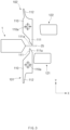
- FIG. 3 is a schematic view of a folding apparatus according to embodiment of the present invention.
- the folding apparatus may be an apparatus that provides the side folding part 30.
- the folding apparatus may fold one, from which the electrode lead 12 does not protrude, of the sealed terraces 24 and 25 of the battery cell 1.
- the folding apparatus may fold the second terrace 25.
- the terrace is denoted as a reference numeral "25" for convenience of explanation.
- the folding apparatus may include clamping parts 101 and 102 and folding mechanisms 121 and 122.
- the clamping parts 101 and 102 may be provided in a pair disposed to face each other with a portion of the terrace 25 disposed therebetween.
- the terrace 25 may pass between the clamping parts 101 and 102 to protrude to the outside.
- the pair of clamping parts 101 and 102 may include a first clamping part 101 disposed at one side of the terrace 25, and a second clamping part 102 disposed at the other side of the terrace 25.
- Each of the clamping parts 101 and 102 may be provided to be rotatable around a rotary shaft 110a.
- the rotary shaft 110a may be parallel to the terrace 25. As the terrace 25 is parallel to a full-length or full-width direction of the battery cell 1 as described above, the rotary shaft 110a may also be parallel to the full-length or full-width direction of the battery cell 1.
- Each of the clamping parts 101 and 102 may be provided to be movable so that a distance between the rotary shaft 110a and the terrace 25 varies. As one example, each of the clamping parts 101 and 102 may move to be parallel to a thickness direction of the battery cell 1 (direction parallel to a Y-axis in FIG. 3 ).
- Each of the clamping parts 101 and 102 may include a main body 110, a first protrusion 111, and a second protrusion 112.
- the main body 110 may rotate around the rotary shaft 110a.
- the rotary shaft 110a may extend so as to pass through a central portion of the main body 110.
- the main body 110 may extend to be parallel to the terrace 25.
- the main body 110 may have a predetermined width in the thickness direction of the battery cell 1 (direction parallel to the Y-axis in FIG. 3 ), and have a predetermined thickness in a protruding direction of the terrace 25 (direction parallel to an X-axis in FIG. 3 ).
- the first protrusion 111 may protrude from one side portion of the main body 110, and the second protrusion 112 may protrude from the other side portion of the main body 110.
- the first protrusion 111 may protrude toward the terrace 25
- the second protrusion 112 may protrude toward a side opposite to the terrace 25.
- the first protrusion 111 may clamp the terrace 25 (see FIG. 4 ).
- the first protrusion 111 may clamp the terrace 25.
- the initial state may mean a state before the main body 110 rotates.
- the terrace 25 may be clamped between the first protrusion 111 of the first clamping part 101 and the first protrusion 111 of the second clamping part 102.
- the first protrusion 111 may be provided to be inclined with respect to the terrace 25, and include an inclined surface 111a that is in contact with the terrace 25.
- the respective inclined surfaces 111a of the first protrusions 111 of the pair of clamping parts 101 and 102 may be provided to be parallel to each other. That is, the respective first protrusions 111 of the pair of clamping parts 101 and 102 may have an asymmetric shape. Thus, a portion of the terrace 25 may be folded and clamped to be inclined between the pair of inclined surfaces 111a.
- the second protrusion 112 may clamp an inner portion of the terrace 25 than the first protrusion 111 does (see FIG. 7 ).
- the second protrusion 112 may clamp an inner portion than the portion, which has been clamped by the first protrusion 111, of the terrace 25.
- the terrace 25 may be clamped between the second protrusion 112 of the first clamping part 101 and the second protrusion 112 of the second clamping part 102.
- An area on which the inclined surface 111a of the first protrusion 111 is in contact with the terrace 25 may be greater than an area on which the second protrusion 112 is in contact with the terrace 25.
- the folding mechanisms 121 and 122 may be disposed outside the pair of clamping parts 101 and 102 to fold the terrace 25.
- the folding mechanisms 121 and 122 may fold an outer portion of the terrace 25, which protrudes outward from the pair of clamping parts 101 and 102.
- the folding mechanisms 121 and 122 may include a first body 121 and a second body 122.
- Each of the first body 121 and the second body 122 may have an approximately block shape.
- the first body 121 may be disposed outside the first clamping part 101, and the second body 122 may be disposed outside the second clamping part 122.
- the first body 121 and the second body 122 may be disposed at both sides of the terrace 25, respectively.
- the first body 121 may be disposed at one side of the terrace 25 or a virtual boundary to which the terrace 25 is expanded, and the second body 122 may be disposed at the other side.
- Each of the first body 121 and the second body 122 may be provided to be movable biaxially in a first direction and a second direction perpendicular to the first direction.
- the first direction may be parallel to the thickness direction of the battery cell 1 (direction parallel to the Y-axis in FIG. 3 )
- the second direction may be parallel to the protruding direction of the terrace 25 (direction parallel to the X-axis in FIG. 3 ).
- At least one of the first clamping part 101, the second clamping part 102, the first body 121, or the second body 122 may heat the terrace 25.
- at least one of the pair of clamping parts 101 and 102 may heat the terrace 25.
- At least one of the first body 121 or the second body 122 may also heat the terrace 25.
- the first clamping part 101, the second clamping part 102, the first body 121, or the second body 122 may be in contact with the terrace 25 in a state of being heated to a high temperature.
- the high temperature is a temperature, which is remarkably higher than the room temperature, and may mean a temperature that may affect the moldability of the terrace 25. Accordingly, the terrace 25 may be easily folded, and the folded terrace 25 may be prevented from being spread again as much as possible.
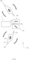
- FIGS. 4 to 8 are schematic views sequentially illustrating operations of a folding apparatus according to embodiment of the present invention.
- respective first protrusions 111 of a pair of clamping parts 101 and 102 may clamp a terrace 25 at both sides.
- the pair of clamping parts 101 and 102 may move so as to be close to each other.
- the pair of clamping parts 101 and 102 may move to be parallel to a thickness direction of a battery cell 1.
- each of the pair of clamping parts 101 and 102 may be in an initial state before rotating.
- a portion of the terrace 25 may be folded and clamped along an inclined surface 111a of each of the first protrusions 111.
- a portion, which is in contact with the inclined surface 111a, of the terrace 25 may be termed a first region
- a portion disposed outward from the first region may be termed a second region
- a portion disposed inward from the first region may be termed a third region.
- the second region and the third region may be provided to be different in height in the thickness direction of the battery cell 1, and the first region may be provided to be inclined and connect the second region to the third region.
- an embodiment of the present invention is not limited thereto, and may provide a modified example in which the first protrusion 111 does not include the inclined surface 111a that is inclined. In this case, even when the terrace 25 is clamped between the first protrusions 111 of the pair of clamping parts 101 and 102, the terrace 25 may be maintained to be flat without being folded.
- a first body 121 may move to fold the terrace 25.
- the first body 121 may move in the thickness of the battery cell 1, and may fold the second region of the terrace 25, which protrudes outward from the first protrusion 111.
- the first body 121 may move to be parallel to the thickness of the battery cell 1 so that the terrace 25 is folded toward the first protrusion 111.
- the first body 121 may move from the outside of the first clamping part 101 to the outside of the second clamping part 102, and may push and fold the terrace 25. As the first body 121 moves, the terrace 25 may be folded along an inner surface of the first body 121.
- the first body 121 may fold the terrace 25 so that the terrace 25 is inclined in a direction opposite to an inclination of the inclined surface 111a of the first protrusion 111.
- the first region of the terrace 25 may be provided to be inclined downward toward the outside along the inclined surface 111a, and the first body 121 may fold the second region of the terrace 25 so that the second region is inclined upward toward the outside.
- the terrace 25 may be folded at a first angle.
- the second region of the terrace 25 may be folded at the first angle (e.g., 90 degrees) on the basis of an initial position.
- the second region of the terrace 25, which protrudes outward from the first protrusion 111, may be folded to have an acute angle with respect to the first region clamped by the first protrusion 111.
- a portion that connects the first region and the second region of the terrace 25 to each other may form a first folding portion 25a.
- the first body 111 may fold the terrace 25 so that the first folding portion 25a has an acute angle. Accordingly, the first folding portion 25a may be more reliably folded, and spring-back in which the first folding portion 25a is spread again may be minimized.
- the pair of clamping parts 101 and 102 may be far away from the terrace 25, and the first body 121 may move to a preset standby position.
- the first body 121 may move so as to be in contact with the first region of the terrace 25 at one side of the terrace 25.
- the pair of clamping parts 101 and 102 may move so as to be far away from each other.
- the pair of clamping parts 101 and 102 may move in the thickness direction of the battery cell 1.
- a second protrusion 112 may rotate so as to face the terrace 25.
- the second body 122 may further fold the terrace 25.
- the second body 122 together with the first body 121 may further fold the terrace 25.
- the second body 122 may move to a position at which the second body 122 faces the first body 121 with the terrace 25 therebetween.
- the second body 122 may move from the outside to the inside.
- the second body 122 may fold the terrace 25 while moving in a direction (e.g., direction opposite to an X-axis) opposite to a protruding direction of the terrace 25.
- the terrace 25 may be pressed and folded between the second body 122 and the first body 121.
- the second body 122 may fold the second region of the terrace 25 so that the second region overlaps the first region.
- the terrace 25 may be further folded at a second angle (e.g., 180 degrees) that is greater than the first angle. That is, the first folding portion 25a of the terrace 25 may be further folded.
- a second angle e.g. 180 degrees
- the second region of the terrace 25 may be folded at the second angle (e.g., 180 degrees) on the basis of the initial position.
- the terrace 25 may be folded so that the second region overlaps the first region.
- first body 121 and the second body 122 may move to be far away from the terrace 25, the respective second protrusions 112 of the pair of clamping parts 101 and 102 may clamp the terrace 25 at both sides.
- the pair of clamping parts 101 and 102 may move so as to be close to each other in a rotated state.
- the pair of clamping parts 101 and 102 may move to be parallel to the thickness direction of the battery cell 1.
- the second protrusions 112 of the pair of clamping parts 101 and 102 may clamp the terrace 25, and in more detail, the third region of the terrace 25 at both the sides.
- the first body 121 may additionally fold the terrace 25 while moving.
- the first body 121 that has been far away from the terrace 25 may move to a preset folding position after the second protrusions 112 clamp the terrace 25.
- the first body 121 may move to the outside of the first clamping part 101, and in more detail, of the second protrusion 112 of the first clamping part 101.
- the first body 121 may further fold the overlappingly folded terrace 25 while moving in the thickness direction of the battery cell 1.
- the first body 121 may move from the outside of the second protrusion 112 of the first clamping part 101 to the outside of the second protrusion 112 of the second clamping part 102. As the first body 121 moves, the terrace 25 protruding outward from the second protrusion 112 may be folded along the inner surface of the first body 121. As the first body 121 moves, the terrace 25 protruding outward from the second protrusion 112 may be folded toward an outer surface of the second protrusion 112 of the second clamping part 102.
- a second folding portion 25b may be provided while the terrace 25 is additionally folded.
- the second folding portion 25b may connect a portion, which is clamped by the second protrusion 112, of the terrace 25 to a portion protruding outward from the second protrusion 112.
- the second folding portion 25b may be provided inward from the first folding portion 25a.
- the terrace 25 may be folded multiple times and molded as the side folding part 30 through the series of operations illustrated in FIGS. 4 to 8 .
- the operations may be performed while maintaining a state in which the battery cell 1, in more detail, the cup part 23 of the battery cell 1, is fixed by a fixing jig (not shown) or the like. That is, the folding apparatus according to an embodiment of the present invention may fold the terrace 25 multiple times in a state in which the battery cell 1 is aligned once.
- the battery cell 1 may be prevented from being damaged by a plurality of aligning operations, the folding consistency of the terrace 25 may be improved, and the manufacturing line is simplified.
- FIG. 9 is a flowchart of a folding method according to another embodiment of the present invention.
- the folding method may include clamping a terrace 25 at both sides by respective first protrusions 111 of a pair of clamping parts 101 and 102 (S10) (hereinafter referred to as the "first clamping process”), folding the terrace 25 by a first body 121 (S20) (hereinafter referred to as the "first folding process"), allowing the pair of clamping parts 101 and 102 to be far away from the terrace 25 (S30) (hereinafter referred to as the "first separating process”), and moving a second body 122 to face the first body 121 with the terrace 25 therebetween so as to further fold the terrace 25 by the second body 122 (S40) (hereinafter referred to as the "second folding process”).
- the respective first protrusions 111 of the pair of clamping parts 101 and 102 may clamp the terrace 25 of an aligned battery cell 1 at both the sides.
- a region, that is, the first region, which is clamped by each of the first protrusions 111, of the terrace 25 may be clamped to be inclined along an inclined surface 111a of the first protrusion 111.
- the terrace 25 may be folded toward an outer surface of the first protrusion 111 of one of the pair of clamping parts 101 and 102 in a direction opposite to the inclined surface 111a.
- the first body 121 may move from the outside of the first protrusion 111 of a first clamping part 101 to the outside of the first protrusion 111 of a second clamping part 102.
- the terrace 25 may be folded toward the outer surface of the first protrusion 111 of the second clamping part 102.
- a first folding portion 25a may be formed on the terrace 25. As the terrace 25 is folded in the direction opposite to the inclined surface 111a, the first folding portion 25a may have an acute angle.
- the pair of clamping parts 101 and 102 may be far away from the terrace 25.
- Each of the clamping parts 101 and 102 may be sufficiently far away from the terrace 25, and then rotate so that a second protrusion 112 faces the terrace 25.
- Each of the clamping parts 101 and 102 may rotate while moving, or may rotate after completely moving.
- the terrace 25 may be overlappingly folded between the first body 122 and the second body 121.
- the first body 121 may move to one side of the terrace 25 after the previous folding of the terrace 25, and the second body 122 may further fold the terrace 25 while moving to the other side of the terrace 25. That is, the first folding portion 25a may be further folded.
- the folding method may further include separating the first body 121 and the second body 122 from the terrace 25 (S50) (hereinafter referred to as the "second separating process”), rotating the pair of clamping parts 101 and 102 and clamping an inner portion of the terrace 25 by the second protrusion 112 than by the first protrusion 111 (S60) (hereinafter referred to as the "second clamping process”), and additionally folding the terrace 25 by the first body 121 (S70) (hereinafter referred to as the "additional folding process”) .
- the first body 121 and the second body 122 may be far away from the terrace 25.
- the first body 121 and the second body 122 may move so as not to interfere with the pair of clamping parts 101 and 102 in the subsequent second clamping process (S60).
- the second body 122 may farther move than the first body 121. This is because that the first body 121 needs to return to a preset folding position for the subsequent additional folding process (S70).
- the respective second protrusions 112 of the pair of clamping parts 101 and 102 may clamp the terrace 25 at both the sides.
- a portion, which is clamped by the second protrusions 112, of the terrace 25 may be disposed inward from the portion having clamped by the first protrusions 111 in the previous first clamping process (S10).
- the first body 121 that has been far away from the terrace 25 may move to the preset folding position, and then may additionally fold the terrace 25.
- the first body 121 may move from the outside of the second protrusion 112 of the first clamping part 101 to the outside of the second protrusion 112 of the second clamping part 102.
- the terrace 25 may be additionally folded so that the overlapping portion of the terrace 25 faces an outer surface of the second protrusion 112 of the second clamping part 102.
- a second folding portion 25b may be formed on the terrace 25.
- At least one of the first clamping part 101, the second clamping part 102, the first body 121, or the second body 122 may perform the first clamping process (S10) to the additional folding process (S70) in a state of being heated to a high temperature. Accordingly, the terrace 25 may be easily folded, and the folded terrace 25 may be prevented from being spread again as much as possible.
- Pouch type battery cell 25 Terrace 101: First clamping part 102: Second clamping part 110: Main body 110a: Rotary shaft 111: First protrusion 111a: Inclined surface 112: Second protrusion 121: First body 122: Second body
Landscapes
- Chemical & Material Sciences (AREA)
- Chemical Kinetics & Catalysis (AREA)
- Electrochemistry (AREA)
- General Chemical & Material Sciences (AREA)
- Engineering & Computer Science (AREA)
- Manufacturing & Machinery (AREA)
- Mechanical Engineering (AREA)
- Sealing Battery Cases Or Jackets (AREA)
- Secondary Cells (AREA)
Abstract
Description
- The present application claims the benefit of the priority of
Korean Patent Application No. 10-2022-0098868, filed on August 8, 2022 - The present invention relates to an apparatus and method for folding a terrace of a pouch type battery case.
- Recently, secondary batteries receive attention as power sources for electric vehicles (EV), hybrid electric vehicles (HEV) and the like, which are proposed as solutions to solve problems such as air pollution caused by existing gasoline vehicles, diesel vehicles, and the like, using fossil fuel.
- While a small-sized mobile device uses one or a few secondary batteries, a medium to large-sized device such as electric vehicle, uses a battery module, in which a plurality of secondary batteries are electrically connected to each other, or a battery pack, in which a plurality of battery modules are electrically connected to each other, due to the need for high output and large capacity.
- It can be said that one of the secondary batteries that attract the most interest among currently commercialized secondary batteries is a lithium secondary battery. According to the shape of an exterior material, the lithium secondary battery may be classified into a can type, a prismatic type, a pouch type, and the like. Among these batteries, pouch type secondary batteries are widely used in medium to large-sized battery modules due to advantages of having high energy density and of being easily stacked.
- A pouch type battery cell has a structure in which an electrode assembly is accommodated in a pouch type battery case, and a terrace of the battery case is sealed. A process of folding at least once the terrace from which an electrode lead does not protrude is performed in order to reduce energy density per volume of the battery cell and to improve sealability. As one example, the sealed terrace may be folded two times in the process, and this is generally termed a double side folding (DSF).
- According to the related art, the terrace is folded through a plurality of processes that are performed at different positions while the battery cell moves along a manufacturing line. Accordingly, the battery cell needs to be aligned in each of the plurality of processes, and thus there are problems that the battery cell is damaged by the aligning operation, folding consistency of the terrace is reduced, and the manufacturing line is complicated.
- An object of the present invention for solving the above problems is to provide a folding apparatus and folding method capable of folding a terrace multiple times in a state in which a pouch type battery cell is aligned once.
- A folding apparatus according to an embodiment of the present invention may fold a terrace of a pouch type battery cell. The folding apparatus may include: a pair of clamping parts facing each other with the terrace therebetween; and a folding mechanism disposed outside the pair of clamping parts to fold the terrace. Each of the clamping parts may include: a body that rotates around a rotary shaft parallel to the terrace; a first protrusion that protrudes from one side portion of the body and clamps the terrace; and a second protrusion protruding from the other side portion of the body, wherein, as the body rotates, the second protrusion clamps an inner portion of the terrace than the first protrusion does.
- The first protrusion may include an inclined surface that is provided to be inclined with respect to the terrace and is in contact with the terrace.
- The respective inclined surfaces of the pair of clamping parts may be provided to be parallel to each other.
- An area on which the inclined surface is in contact with the terrace may be greater than an area on which the second protrusion is in contact with the terrace.
- The clamping part may be provided to be movable so that a distance between the rotary shaft and the terrace varies.
- At least one of the pair of clamping parts may heat the terrace.
- The folding mechanism may include: a first body that moves so that when the first protrusion of the clamping part clamps the terrace, the terrace is folded toward the first protrusion; and a second body that moves so that when the pair of clamping parts are far away from the terrace, the terrace is further folded toward the first body.
- When the first body and the second body are far away from the terrace, the clamping part may rotate so that the second protrusion clamps the terrace.
- When the second protrusion of the clamping part clamps the terrace, the first body may additionally fold the terrace while moving.
- Each of the first body and the second body may be provided to be movable biaxially in a first direction, which is parallel to a thickness direction of the battery cell, and a second direction perpendicular to the first direction.
- At least one of the first body or the second body may heat the terrace.
- A folding method according to an embodiment of the present invention may fold a terrace of a pouch type battery cell. The folding method may include: clamping the terrace at both sides by respective first protrusions of a pair of clamping parts; folding the terrace by a first body disposed outside the pair of clamping parts; allowing the pair of clamping parts to be far away from the terrace; and moving a second body to face the first body with the terrace therebetween so as to further fold the terrace by the second body.
- A region, which is clamped by each of the first protrusions, of the terrace may be clamped to be inclined along an inclined surface of the first protrusion.
- In the folding of the terrace by the first body, the terrace may be folded toward an outer surface of the first protrusion of one of the pair of clamping parts in a direction opposite to the inclined surface.
- In the further folding of the terrace by the second body, the terrace may be overlappingly folded between the first body and the second body.
- The folding method may further include: separating the first body and the second body from the terrace; rotating the pair of clamping parts so that respective second protrusions of the pair of clamping parts clamp an inner portion of the terrace than the first protrusions do; and additionally folding the terrace by the first body.
- In the additionally folding of the terrace by the first body, the terrace may be folded toward an outer surface of the second protrusion of one of the pair of clamping parts.
- According to the preferred embodiments of the present invention, the terrace may be folded multiple times in the state in which the battery cell is aligned once. Accordingly, unlike the related art, the battery cell may be prevented from being damaged by the plurality of aligning operations.
- As the damage of the battery cell is minimized, the stab on the outer appearance and the damage to the insulation resistance may be minimized.
- Moreover, the folding consistency of the terrace may be improved, and the folding deviation between the products may be minimized.
- Furthermore, the battery cell may be simplified in terms of the configuration and the control of the manufacturing line.
- In addition, the effects may be included which could be easily predicted by those of ordinary skill in the art from the configurations according to the preferred embodiments of the present invention.
- The following drawings attached in this specification illustrate a preferred embodiment of the present invention and function to make further understood the technical spirit of the present invention along with the detailed description of the invention. The present invention should not be construed as being limited to only the drawings.
-
FIG. 1 is an assembly view of a pouch type battery cell. -
FIG. 2 is a plan view of a pouch type battery cell. -
FIG. 3 is a schematic view of a folding apparatus according to an embodiment of the present invention. -
FIGS. 4 to 8 are schematic views sequentially illustrating operations of a folding apparatus according to embodiment of the present invention. -
FIG. 9 is a flowchart of a folding method according to another embodiment of the present invention. - Hereinafter, preferred embodiments of the present invention will be described in detail with reference to the accompanying drawings to enable those of ordinary skill in the art to which the present invention pertains to easily carry out the present invention. The present invention may, however, be embodied in different forms and should not be construed as limited by the embodiments set forth herein.
- The parts unrelated to the description, or the detailed descriptions of related well-known art that may unnecessarily obscure subject matters of the present invention, will be ruled out in order to clearly describe the present invention. Like reference numerals refer to like elements throughout the whole specification.
- Moreover, terms or words used in this specification and claims should not be restrictively interpreted as ordinary meanings or dictionary-based meanings, but should be interpreted as meanings and concepts conforming to the scope of the present invention on the basis of the principle that an inventor can properly define the concept of a term to describe and explain his or her invention in the best ways.
-
FIG. 1 is an assembly view of a pouch type battery cell.FIG. 2 is a plan view of a pouch type battery cell. - A pouch type battery cell 1 (hereinafter referred to as the "battery cell") may include an
electrode assembly 10 and a pouch type battery case 20 (hereinafter referred to as the "pouch") . - The
electrode assembly 10 may be provided by stacking a positive electrode and a negative electrode alternately with a separator therebetween. That is, theelectrode assembly 10 may include the plurality of electrodes, and the separator interposed between the plurality of electrodes in order to insulates the plurality of electrodes from each other. Theelectrode assembly 10 together with an electrolyte may be accommodated in thepouch 20, and in more detail, in a pair ofcup parts 22 to be described later. - The
electrode assembly 10 may include a stacked type, a jelly-roll-type, a stack and folding type, and the like, and the type thereof is not limited. - The
electrode assembly 10 may include anelectrode tab 11. Theelectrode tab 11 may be connected to each of the positive electrode and the negative electrode of theelectrode assembly 10, and protrude from theelectrode assembly 10 to the outside so as to serve as a path through which an electron moves between the inside and the outside of theelectrode assembly 10. - The
electrode tab 11 may be provided by cutting out a non-coating portion of an electrode current collector, or may be provided by connecting a separate conductive member to the non-coating portion through ultrasonic welding or the like. - The
electrode tab 11 may include apositive electrode tab 11a connected to the positive electrode, and anegative electrode tab 11b connected to the negative electrode. Thepositive electrode tab 11a and thenegative electrode tab 11b may protrude in different directions of theelectrode tab 11, but an embodiment of the present invention is not limited thereto. For example, thepositive electrode tab 11a and thenegative electrode tab 11b may protrude in various directions such as protruding from one side in the same direction so as to be parallel to each other. - An
electrode lead 12 that supplies electricity to the outside of asecondary battery 1 may be connected to theelectrode tab 11 of theelectrode assembly 10 through spot welding or the like. Theelectrode lead 12 may have a portion surrounded by aninsulation part 14. Theinsulation part 14 may be disposed to be limited on aterrace first case 21 and asecond case 22 of thepouch 20 are thermally fused to each other. Accordingly, theinsulation part 14 may insulate theelectrode lead 12 from thepouch 20, and maintain sealing of thepouch 20. In general, an insulation tape that is easily attached to theelectrode lead 12 and has a relatively small thickness may be much used as theinsulation part 14. However, an embodiment of the present invention is not limited thereto, and various members may be used as long as the members are capable of insulating theelectrode lead 12. - The
electrode lead 12 may have one end connected to theelectrode tab 11, and the other end protruding to the outside of thepouch 20. Theelectrode lead 12 may include apositive electrode lead 12a connected to thepositive electrode tab 11a, and anegative electrode lead 12b connected to thenegative electrode tab 11b. - The
electrode lead 12 may electrically connect theelectrode assembly 10 to the outside. In addition, as each of thepositive electrode tab 11a and thenegative electrode tab 11b protrudes in various directions, each of thepositive electrode lead 12a and thenegative electrode lead 12b may also extend in various directions. - The
pouch 20 may accommodate theelectrode assembly 10 therein, and may be provided by molding a laminate sheet. In more detail, when drawing molding is performed on the laminate sheet having flexibility by using a die, a punch, and the like, a portion of the laminate sheet may be stretched to provide acup part 23 including an accommodation space S1 having a pocket shape so that thepouch 20 is manufactured. - The
pouch 20 may accommodate theelectrode assembly 10 so that a portion of theelectrode lead 12 is exposed, and then be sealed. Thispouch 20 may include a pair ofcases first case 21 and thesecond case 22. - Hereinafter, as illustrated in
FIG. 1 , a case in which one side of thefirst case 21 is connected to one side of thesecond case 22 will be described as an example. However, an embodiment of the present invention is not limited thereto, and thefirst case 21 and thesecond case 22 may also be separated from each other and manufactured separately. - The
cup part 23 may be provided in at least one of thefirst case 21 or thesecond case 22 so that the accommodating space S1 capable of accommodating theelectrode assembly 10 is provided. Thecup part 23 may have a recessed shape. Thecup part 23 may include abottom surface 23a and acircumferential surface 23b. - As illustrated in
FIG. 1 , thefirst case 21 and thesecond case 22 may be connected to each other through abridge 26. Thebridge 26 may be provided between a pair ofcup parts 23. Thebridge 26 may extend to be parallel to a full-length or full-width direction of theelectrode assembly 10. However, an embodiment of the present invention is not limited thereto, and thefirst case 21 and thesecond case 22 may be provided to be separated from each other. - Each of the
cases terraces cup part 23. In more detail, theterraces first terrace 24 parallel to one of a full length and a full width of theelectrode assembly 10, and asecond terrace 25 parallel to the other. - For example, the
second terrace 25 may be disposed at a side opposite to thebridge 26 on the basis of thecup part 23, and thefirst terrace 24 may connect an end of thesecond terrace 25 and an end of thebridge 26 to each other. - When the
bridge 26 is folded, theterraces first case 21 and theterraces second case 22 may be in contact with each other. Here, theinsulation part 14 of theelectrode assembly 10 may be disposed between theterraces cases insulation part 14 may be disposed between thefirst terraces 24 of the pair ofcases terraces first case 21 and theterraces second case 22 may be sealed to each other in a state of being in contact with each other. - The
pouch 20 may include aside folding part 30 provided by folding one of theterraces terraces electrode lead 12 does not protrude, may be folded to provide theside folding part 30. - For example, as illustrated in
FIG. 2 , when theelectrode lead 12 protrudes to the outside of thepouch 20 through thefirst terraces 24, thesecond terraces 25 may be folded to provide theside folding part 30. That is, theside folding part 30 may be provided at the side opposite to thebridge 26. When thefirst case 21 and thesecond case 22 are provided separately without being connected through thebridge 26, theside folding part 30 may be provided on each of both side portions of thebattery cell 1. -
FIG. 3 is a schematic view of a folding apparatus according to embodiment of the present invention. - The folding apparatus according to embodiment of the present invention may be an apparatus that provides the
side folding part 30. The folding apparatus may fold one, from which theelectrode lead 12 does not protrude, of the sealedterraces battery cell 1. For example, the folding apparatus may fold thesecond terrace 25. Hereinafter, the terrace is denoted as a reference numeral "25" for convenience of explanation. - The folding apparatus may include clamping
parts folding mechanisms - The clamping
parts terrace 25 disposed therebetween. Theterrace 25 may pass between the clampingparts parts first clamping part 101 disposed at one side of theterrace 25, and asecond clamping part 102 disposed at the other side of theterrace 25. - Each of the clamping
parts rotary shaft 110a. Therotary shaft 110a may be parallel to theterrace 25. As theterrace 25 is parallel to a full-length or full-width direction of thebattery cell 1 as described above, therotary shaft 110a may also be parallel to the full-length or full-width direction of thebattery cell 1. - Each of the clamping
parts rotary shaft 110a and theterrace 25 varies. As one example, each of the clampingparts FIG. 3 ). - Each of the clamping
parts main body 110, afirst protrusion 111, and asecond protrusion 112. - The
main body 110 may rotate around therotary shaft 110a. Therotary shaft 110a may extend so as to pass through a central portion of themain body 110. Themain body 110 may extend to be parallel to theterrace 25. In addition, themain body 110 may have a predetermined width in the thickness direction of the battery cell 1 (direction parallel to the Y-axis inFIG. 3 ), and have a predetermined thickness in a protruding direction of the terrace 25 (direction parallel to an X-axis inFIG. 3 ). - The
first protrusion 111 may protrude from one side portion of themain body 110, and thesecond protrusion 112 may protrude from the other side portion of themain body 110. For example, thefirst protrusion 111 may protrude toward theterrace 25, and thesecond protrusion 112 may protrude toward a side opposite to theterrace 25. - The
first protrusion 111 may clamp the terrace 25 (seeFIG. 4 ). In more detail, when themain body 110 is in an initial state, thefirst protrusion 111 may clamp theterrace 25. The initial state may mean a state before themain body 110 rotates. - The
terrace 25 may be clamped between thefirst protrusion 111 of thefirst clamping part 101 and thefirst protrusion 111 of thesecond clamping part 102. - The
first protrusion 111 may be provided to be inclined with respect to theterrace 25, and include aninclined surface 111a that is in contact with theterrace 25. The respectiveinclined surfaces 111a of thefirst protrusions 111 of the pair of clampingparts first protrusions 111 of the pair of clampingparts terrace 25 may be folded and clamped to be inclined between the pair ofinclined surfaces 111a. - The
second protrusion 112 may clamp an inner portion of theterrace 25 than thefirst protrusion 111 does (seeFIG. 7 ). In more detail, when themain body 110 is in a rotated state, thesecond protrusion 112 may clamp an inner portion than the portion, which has been clamped by thefirst protrusion 111, of theterrace 25. Theterrace 25 may be clamped between thesecond protrusion 112 of thefirst clamping part 101 and thesecond protrusion 112 of thesecond clamping part 102. - An area on which the
inclined surface 111a of thefirst protrusion 111 is in contact with theterrace 25 may be greater than an area on which thesecond protrusion 112 is in contact with theterrace 25. - The
folding mechanisms parts terrace 25. Thefolding mechanisms terrace 25, which protrudes outward from the pair of clampingparts - In more detail, the
folding mechanisms first body 121 and asecond body 122. Each of thefirst body 121 and thesecond body 122 may have an approximately block shape. - The
first body 121 may be disposed outside thefirst clamping part 101, and thesecond body 122 may be disposed outside thesecond clamping part 122. - The
first body 121 and thesecond body 122 may be disposed at both sides of theterrace 25, respectively. In more detail, thefirst body 121 may be disposed at one side of theterrace 25 or a virtual boundary to which theterrace 25 is expanded, and thesecond body 122 may be disposed at the other side. - Each of the
first body 121 and thesecond body 122 may be provided to be movable biaxially in a first direction and a second direction perpendicular to the first direction. For example, the first direction may be parallel to the thickness direction of the battery cell 1 (direction parallel to the Y-axis inFIG. 3 ), and the second direction may be parallel to the protruding direction of the terrace 25 (direction parallel to the X-axis inFIG. 3 ). - Hereinafter, respective operations of the
first body 121 and thesecond body 122 will be described in detail. - At least one of the
first clamping part 101, thesecond clamping part 102, thefirst body 121, or thesecond body 122 may heat theterrace 25. Preferably, at least one of the pair of clampingparts terrace 25. At least one of thefirst body 121 or thesecond body 122 may also heat theterrace 25. - In more detail, during the folding of the
terrace 25, at least one of thefirst clamping part 101, thesecond clamping part 102, thefirst body 121, or thesecond body 122 may be in contact with theterrace 25 in a state of being heated to a high temperature. The high temperature is a temperature, which is remarkably higher than the room temperature, and may mean a temperature that may affect the moldability of theterrace 25. Accordingly, theterrace 25 may be easily folded, and the foldedterrace 25 may be prevented from being spread again as much as possible. -
FIGS. 4 to 8 are schematic views sequentially illustrating operations of a folding apparatus according to embodiment of the present invention. - As illustrated in
FIG. 4 , respectivefirst protrusions 111 of a pair of clampingparts terrace 25 at both sides. In more detail, the pair of clampingparts parts battery cell 1. Here, each of the pair of clampingparts - Accordingly, a portion of the
terrace 25 may be folded and clamped along aninclined surface 111a of each of thefirst protrusions 111. For convenience of explanation, a portion, which is in contact with theinclined surface 111a, of theterrace 25 may be termed a first region, a portion disposed outward from the first region may be termed a second region, and a portion disposed inward from the first region may be termed a third region. In this case, the second region and the third region may be provided to be different in height in the thickness direction of thebattery cell 1, and the first region may be provided to be inclined and connect the second region to the third region. - However, an embodiment of the present invention is not limited thereto, and may provide a modified example in which the
first protrusion 111 does not include theinclined surface 111a that is inclined. In this case, even when theterrace 25 is clamped between thefirst protrusions 111 of the pair of clampingparts terrace 25 may be maintained to be flat without being folded. - As illustrated in
FIG. 5 , when thefirst protrusions 111 of the clampingparts terrace 25, afirst body 121 may move to fold theterrace 25. - In more detail, in a state in which the first region of the
terrace 25 is clamped between thefirst protrusions 111 of the pair of clampingparts first body 121 may move in the thickness of thebattery cell 1, and may fold the second region of theterrace 25, which protrudes outward from thefirst protrusion 111. - The
first body 121 may move to be parallel to the thickness of thebattery cell 1 so that theterrace 25 is folded toward thefirst protrusion 111. Thefirst body 121 may move from the outside of thefirst clamping part 101 to the outside of thesecond clamping part 102, and may push and fold theterrace 25. As thefirst body 121 moves, theterrace 25 may be folded along an inner surface of thefirst body 121. - The
first body 121 may fold theterrace 25 so that theterrace 25 is inclined in a direction opposite to an inclination of theinclined surface 111a of thefirst protrusion 111. For example, the first region of theterrace 25 may be provided to be inclined downward toward the outside along theinclined surface 111a, and thefirst body 121 may fold the second region of theterrace 25 so that the second region is inclined upward toward the outside. - Accordingly, the
terrace 25 may be folded at a first angle. In more detail, the second region of theterrace 25 may be folded at the first angle (e.g., 90 degrees) on the basis of an initial position. - In more detail, the second region of the
terrace 25, which protrudes outward from thefirst protrusion 111, may be folded to have an acute angle with respect to the first region clamped by thefirst protrusion 111. In this case, a portion that connects the first region and the second region of theterrace 25 to each other may form afirst folding portion 25a. - That is, as the
inclined surface 111a of thefirst protrusion 111 is provided to be inclined, thefirst body 111 may fold theterrace 25 so that thefirst folding portion 25a has an acute angle. Accordingly, thefirst folding portion 25a may be more reliably folded, and spring-back in which thefirst folding portion 25a is spread again may be minimized. - As illustrated in
FIG. 6 , after thefirst body 121 folds theterrace 25, the pair of clampingparts terrace 25, and thefirst body 121 may move to a preset standby position. In more detail, thefirst body 121 may move so as to be in contact with the first region of theterrace 25 at one side of theterrace 25. - The pair of clamping
parts parts battery cell 1. In a state in which the pair of clampingparts terrace 25, asecond protrusion 112 may rotate so as to face theterrace 25. - When the pair of clamping
parts terrace 25, thesecond body 122 may further fold theterrace 25. In more detail, thesecond body 122 together with thefirst body 121 may further fold theterrace 25. - The
second body 122 may move to a position at which thesecond body 122 faces thefirst body 121 with theterrace 25 therebetween. Thesecond body 122 may move from the outside to the inside. In more detail, thesecond body 122 may fold theterrace 25 while moving in a direction (e.g., direction opposite to an X-axis) opposite to a protruding direction of theterrace 25. - The
terrace 25 may be pressed and folded between thesecond body 122 and thefirst body 121. In more detail, thesecond body 122 may fold the second region of theterrace 25 so that the second region overlaps the first region. - Accordingly, the
terrace 25 may be further folded at a second angle (e.g., 180 degrees) that is greater than the first angle. That is, thefirst folding portion 25a of theterrace 25 may be further folded. - In more detail, the second region of the
terrace 25 may be folded at the second angle (e.g., 180 degrees) on the basis of the initial position. Preferably, theterrace 25 may be folded so that the second region overlaps the first region. - As illustrated in
FIG. 7 , when thefirst body 121 and thesecond body 122 are far away from theterrace 25, the clampingparts second protrusions 112 clamp theterrace 25. - In more detail, the
first body 121 and thesecond body 122 may move to be far away from theterrace 25, the respectivesecond protrusions 112 of the pair of clampingparts terrace 25 at both sides. The pair of clampingparts parts battery cell 1. - The
second protrusions 112 of the pair of clampingparts terrace 25, and in more detail, the third region of theterrace 25 at both the sides. - As illustrated in
FIG. 8 , when thesecond protrusions 112 of the clampingparts terrace 25, thefirst body 121 may additionally fold theterrace 25 while moving. - In more detail, the
first body 121 that has been far away from theterrace 25 may move to a preset folding position after thesecond protrusions 112 clamp theterrace 25. Thefirst body 121 may move to the outside of thefirst clamping part 101, and in more detail, of thesecond protrusion 112 of thefirst clamping part 101. - Thereafter, the
first body 121 may further fold the overlappingly foldedterrace 25 while moving in the thickness direction of thebattery cell 1. - The
first body 121 may move from the outside of thesecond protrusion 112 of thefirst clamping part 101 to the outside of thesecond protrusion 112 of thesecond clamping part 102. As thefirst body 121 moves, theterrace 25 protruding outward from thesecond protrusion 112 may be folded along the inner surface of thefirst body 121. As thefirst body 121 moves, theterrace 25 protruding outward from thesecond protrusion 112 may be folded toward an outer surface of thesecond protrusion 112 of thesecond clamping part 102. - Accordingly, a
second folding portion 25b may be provided while theterrace 25 is additionally folded. Thesecond folding portion 25b may connect a portion, which is clamped by thesecond protrusion 112, of theterrace 25 to a portion protruding outward from thesecond protrusion 112. Thesecond folding portion 25b may be provided inward from thefirst folding portion 25a. - As above, the
terrace 25 may be folded multiple times and molded as theside folding part 30 through the series of operations illustrated inFIGS. 4 to 8 . The operations may be performed while maintaining a state in which thebattery cell 1, in more detail, thecup part 23 of thebattery cell 1, is fixed by a fixing jig (not shown) or the like. That is, the folding apparatus according to an embodiment of the present invention may fold theterrace 25 multiple times in a state in which thebattery cell 1 is aligned once. - Accordingly, unlike the related art, there are advantages that the
battery cell 1 may be prevented from being damaged by a plurality of aligning operations, the folding consistency of theterrace 25 may be improved, and the manufacturing line is simplified. -
FIG. 9 is a flowchart of a folding method according to another embodiment of the present invention. - Hereinafter, a folding method using the folding apparatus described above will be described as another embodiment of the present invention.
- The folding method may include clamping a
terrace 25 at both sides by respectivefirst protrusions 111 of a pair of clampingparts 101 and 102 (S10) (hereinafter referred to as the "first clamping process"), folding theterrace 25 by a first body 121 (S20) (hereinafter referred to as the "first folding process"), allowing the pair of clampingparts second body 122 to face thefirst body 121 with theterrace 25 therebetween so as to further fold theterrace 25 by the second body 122 (S40) (hereinafter referred to as the "second folding process"). - In the first clamping process (S10), the respective
first protrusions 111 of the pair of clampingparts terrace 25 of an alignedbattery cell 1 at both the sides. A region, that is, the first region, which is clamped by each of thefirst protrusions 111, of theterrace 25 may be clamped to be inclined along aninclined surface 111a of thefirst protrusion 111. - The contents described above with reference to
FIG. 4 apply to the first clamping process (S10). - In the first folding process (S20), the
terrace 25 may be folded toward an outer surface of thefirst protrusion 111 of one of the pair of clampingparts inclined surface 111a. In more detail, thefirst body 121 may move from the outside of thefirst protrusion 111 of afirst clamping part 101 to the outside of thefirst protrusion 111 of asecond clamping part 102. According to the movement of thefirst body 121, theterrace 25 may be folded toward the outer surface of thefirst protrusion 111 of thesecond clamping part 102. Accordingly, afirst folding portion 25a may be formed on theterrace 25. As theterrace 25 is folded in the direction opposite to theinclined surface 111a, thefirst folding portion 25a may have an acute angle. - The contents described above with reference to
FIG. 5 apply to the first folding process (S20). - In the first separating process (S30), the pair of clamping
parts terrace 25. Each of the clampingparts terrace 25, and then rotate so that asecond protrusion 112 faces theterrace 25. Each of the clampingparts - In the second folding process (S40), the
terrace 25 may be overlappingly folded between thefirst body 122 and thesecond body 121. In more detail, thefirst body 121 may move to one side of theterrace 25 after the previous folding of theterrace 25, and thesecond body 122 may further fold theterrace 25 while moving to the other side of theterrace 25. That is, thefirst folding portion 25a may be further folded. - The contents described above with reference to
FIG. 6 apply to the first separating process (S30) and the second folding process (S40). - The folding method may further include separating the
first body 121 and thesecond body 122 from the terrace 25 (S50) (hereinafter referred to as the "second separating process"), rotating the pair of clampingparts terrace 25 by thesecond protrusion 112 than by the first protrusion 111 (S60) (hereinafter referred to as the "second clamping process"), and additionally folding theterrace 25 by the first body 121 (S70) (hereinafter referred to as the "additional folding process") . - In the second separating process (S50), the
first body 121 and thesecond body 122 may be far away from theterrace 25. Thefirst body 121 and thesecond body 122 may move so as not to interfere with the pair of clampingparts - The
second body 122 may farther move than thefirst body 121. This is because that thefirst body 121 needs to return to a preset folding position for the subsequent additional folding process (S70). - In the second clamping process (S60), the respective
second protrusions 112 of the pair of clampingparts terrace 25 at both the sides. A portion, which is clamped by thesecond protrusions 112, of theterrace 25 may be disposed inward from the portion having clamped by thefirst protrusions 111 in the previous first clamping process (S10). - The contents described above with reference to
FIG. 7 apply to the second separating process (S50) and the second clamping process (S60). - In the additional folding process (S70), the
first body 121 that has been far away from theterrace 25 may move to the preset folding position, and then may additionally fold theterrace 25. Thefirst body 121 may move from the outside of thesecond protrusion 112 of thefirst clamping part 101 to the outside of thesecond protrusion 112 of thesecond clamping part 102. Accordingly, theterrace 25 may be additionally folded so that the overlapping portion of theterrace 25 faces an outer surface of thesecond protrusion 112 of thesecond clamping part 102. Accordingly, asecond folding portion 25b may be formed on theterrace 25. - The contents described above with reference to
FIG. 8 apply to the additional folding process (S70). - At least one of the
first clamping part 101, thesecond clamping part 102, thefirst body 121, or thesecond body 122 may perform the first clamping process (S10) to the additional folding process (S70) in a state of being heated to a high temperature. Accordingly, theterrace 25 may be easily folded, and the foldedterrace 25 may be prevented from being spread again as much as possible. - The description of the present invention is intended to be illustrative, and various changes and modifications can be made by those of ordinary skill in the art to which the present invention pertains, without departing from the spirit and scope of the present invention as defined by the appended claims.
- Therefore, the embodiments set forth herein are to describe the technical spirit of the present invention and not to limit. The scope of the technical spirit of the present invention is not limited by the embodiments.
- Moreover, the protective scope of the present invention should be determined by reasonable interpretation of the appended claims and all technical concepts coming within the equivalency range of the present application should be interpreted to be in the scope of the right of the present application.
-
1: Pouch type battery cell 25: Terrace 101: First clamping part 102: Second clamping part 110: Main body 110a: Rotary shaft 111: First protrusion 111a: Inclined surface 112: Second protrusion 121: First body 122: Second body
Claims (17)
- A folding apparatus for folding a terrace of a pouch type battery cell, the folding apparatus comprising:a pair of clamping parts facing each other with the terrace therebetween; anda folding mechanism disposed outside the pair of clamping parts to fold the terrace,wherein each of the clamping parts comprises:a body configured to rotate around a rotary shaft parallel to the terrace;a first protrusion protruding from one side portion of the body and configured to clamp the terrace; anda second protrusion protruding from the other side portion of the body, wherein, as the body rotates, the second protrusion clamps an inner portion of the terrace than the first protrusion does.
- The folding apparatus of claim 1, wherein the first protrusion comprises an inclined surface that is provided to be inclined with respect to the terrace and is in contact with the terrace.
- The folding apparatus of claim 2, wherein the respective inclined surfaces of the pair of clamping parts are provided to be parallel to each other.
- The folding apparatus of claim 2, wherein an area on which the inclined surface is in contact with the terrace is greater than an area on which the second protrusion is in contact with the terrace.
- The folding apparatus of claim 1, wherein the clamping part is provided to be movable so that a distance between the rotary shaft and the terrace varies.
- The folding apparatus of claim 1, wherein at least one of the pair of clamping parts is configured to heat the terrace.
- The folding apparatus of claim 1, wherein the folding mechanism comprises:a first body configured to move so that when the first protrusion of the clamping part clamps the terrace, the terrace is folded toward the first protrusion; anda second body configured to move so that when the pair of clamping parts are far away from the terrace, the terrace is further folded toward the first body.
- The folding apparatus of claim 7, wherein, when the first body and the second body are far away from the terrace, the clamping part rotates so that the second protrusion clamps the terrace.
- The folding apparatus of claim 8, wherein, when the second protrusion of the clamping part clamps the terrace, the first body is configured to additionally fold the terrace while moving.
- The folding apparatus of claim 7, wherein each of the first body and the second body is provided to be movable biaxially in a first direction, which is parallel to a thickness direction of the battery cell, and a second direction perpendicular to the first direction.
- The folding apparatus of claim 1, wherein at least one of the first body or the second body is configured to heat the terrace.
- A folding method for folding a terrace of a pouch type battery cell, the folding method comprising:clamping the terrace at both sides by respective first protrusions of a pair of clamping parts;folding the terrace by a first body disposed outside the pair of clamping parts;allowing the pair of clamping parts to be far away from the terrace; andmoving a second body to face the first body with the terrace therebetween so as to further fold the terrace by the second body.
- The folding method of claim 12, wherein a region, which is clamped by each of the first protrusions, of the terrace is clamped to be inclined along an inclined surface of the first protrusion.
- The folding method of claim 13, wherein, in the folding of the terrace by the first body, the terrace is folded toward an outer surface of the first protrusion of one of the pair of clamping parts in a direction opposite to the inclined surface.
- The folding method of claim 12, wherein, in the further folding of the terrace by the second body, the terrace is overlappingly folded between the first body and the second body.
- The folding method of claim 12, further comprising:separating the first body and the second body from the terrace;rotating the pair of clamping parts so that respective second protrusions of the pair of clamping parts clamp an inner portion of the terrace than the first protrusions do; andadditionally folding the terrace by the first body.
- The folding method of claim 16, wherein, in the additionally folding of the terrace by the first body, the terrace is folded toward an outer surface of the second protrusion of one of the pair of clamping parts.
Applications Claiming Priority (2)
| Application Number | Priority Date | Filing Date | Title |
|---|---|---|---|
| KR1020220098868A KR20240020602A (en) | 2022-08-08 | 2022-08-08 | Folding apparatus and method |
| PCT/KR2023/011066 WO2024034941A1 (en) | 2022-08-08 | 2023-07-28 | Folding device and folding method |
Publications (2)
| Publication Number | Publication Date |
|---|---|
| EP4550491A1 true EP4550491A1 (en) | 2025-05-07 |
| EP4550491A4 EP4550491A4 (en) | 2026-03-11 |
Family
ID=89852035
Family Applications (1)
| Application Number | Title | Priority Date | Filing Date |
|---|---|---|---|
| EP23852822.8A Pending EP4550491A4 (en) | 2022-08-08 | 2023-07-28 | FOLDING DEVICE AND FOLDING METHOD |
Country Status (6)
| Country | Link |
|---|---|
| US (1) | US20260038864A1 (en) |
| EP (1) | EP4550491A4 (en) |
| JP (1) | JP7797764B2 (en) |
| KR (1) | KR20240020602A (en) |
| CN (1) | CN119605007A (en) |
| WO (1) | WO2024034941A1 (en) |
Family Cites Families (6)
| Publication number | Priority date | Publication date | Assignee | Title |
|---|---|---|---|---|
| JP2001160379A (en) | 1999-12-01 | 2001-06-12 | Toshiba Battery Co Ltd | Exterior molding equipment for film exterior type batteries |
| KR20180010563A (en) * | 2016-07-21 | 2018-01-31 | 충북대학교 산학협력단 | 2nd Pouch Side Continuous Folding System |
| KR101974443B1 (en) * | 2018-04-09 | 2019-05-02 | 김영훈 | Terrace automatic folding device of secondary battery cell |
| KR102403858B1 (en) * | 2019-09-30 | 2022-06-02 | 에스케이온 주식회사 | Folding apparatus and method for pouch case of battery cell |
| KR102148997B1 (en) * | 2019-12-03 | 2020-08-28 | 주식회사 와이에이치티 | Folding apparature of folding system for folding terrace of secondary battery cell |
| KR102104319B1 (en) * | 2020-01-23 | 2020-04-24 | 주식회사 와이에이치티 | Heater press apparature included in folding system for heat pressurizing to terrace of secondary battery cell |
-
2022
- 2022-08-08 KR KR1020220098868A patent/KR20240020602A/en active Pending
-
2023
- 2023-07-28 WO PCT/KR2023/011066 patent/WO2024034941A1/en not_active Ceased
- 2023-07-28 EP EP23852822.8A patent/EP4550491A4/en active Pending
- 2023-07-28 JP JP2025504401A patent/JP7797764B2/en active Active
- 2023-07-28 US US19/099,117 patent/US20260038864A1/en active Pending
- 2023-07-28 CN CN202380056613.4A patent/CN119605007A/en active Pending
Also Published As
| Publication number | Publication date |
|---|---|
| US20260038864A1 (en) | 2026-02-05 |
| KR20240020602A (en) | 2024-02-15 |
| EP4550491A4 (en) | 2026-03-11 |
| JP2025526520A (en) | 2025-08-14 |
| CN119605007A (en) | 2025-03-11 |
| WO2024034941A1 (en) | 2024-02-15 |
| JP7797764B2 (en) | 2026-01-14 |
Similar Documents
| Publication | Publication Date | Title |
|---|---|---|
| US11935997B2 (en) | Pouch exterior for secondary battery, pouch-type secondary battery using the pouch exterior, and method of manufacturing the pouch-type secondary battery | |
| JP2024534980A (en) | Electrode assembly and manufacturing method thereof, battery cell, battery and power consuming device | |
| WO2019121332A1 (en) | Pouch cell and method of manufacturing same | |
| US10992005B2 (en) | Deep pouch cell and method of manufacturing same | |
| US20220102816A1 (en) | Secondary battery | |
| EP4539220A1 (en) | Pouch-type battery cell, and method for manufacturing same | |
| US20230178861A1 (en) | Secondary battery | |
| US20170207483A1 (en) | Battery cell | |
| CN112670677A (en) | Battery unit for electric vehicle and method for manufacturing same | |
| EP4471970A1 (en) | Secondary battery | |
| JP2008123955A (en) | Method for manufacturing current collector and method for manufacturing power storage device | |
| US12519162B2 (en) | Battery cell and method of manufacturing the same | |
| KR101112450B1 (en) | Secondary Battery of Improved Sealability | |
| CN116487674A (en) | secondary battery | |
| US20260038864A1 (en) | Folding Apparatus and Folding Method | |
| KR20240020603A (en) | Folding apparatus and method | |
| JP7529632B2 (en) | Secondary battery | |
| WO2019054620A1 (en) | Battery cell and method for manufacturing electrode lead | |
| US20260112678A1 (en) | Battery cell manufacturing apparatus and method | |
| US20260135134A1 (en) | Apparatus for manufacturing battery cell | |
| US20250337003A1 (en) | Battery and method for manufacturing the battery | |
| US20240332687A1 (en) | Battery cell, manufacturing device for battery cell and manufacturing method of battery cell | |
| US20260045530A1 (en) | Strip terminal alignment device and method of manufacturing rechargeable battery using the same | |
| EP4517945A1 (en) | Pouch-type battery case, pouch-type secondary battery comprising same, method for manufacturing pouch-type battery case, and molding jig for manufacturing pouch-type battery case | |
| EP4726833A1 (en) | Secondary battery pressing device and secondary battery pressing method using same |
Legal Events
| Date | Code | Title | Description |
|---|---|---|---|
| STAA | Information on the status of an ep patent application or granted ep patent |
Free format text: STATUS: THE INTERNATIONAL PUBLICATION HAS BEEN MADE |
|
| PUAI | Public reference made under article 153(3) epc to a published international application that has entered the european phase |
Free format text: ORIGINAL CODE: 0009012 |
|
| STAA | Information on the status of an ep patent application or granted ep patent |
Free format text: STATUS: REQUEST FOR EXAMINATION WAS MADE |
|
| 17P | Request for examination filed |
Effective date: 20250131 |
|
| AK | Designated contracting states |
Kind code of ref document: A1 Designated state(s): AL AT BE BG CH CY CZ DE DK EE ES FI FR GB GR HR HU IE IS IT LI LT LU LV MC ME MK MT NL NO PL PT RO RS SE SI SK SM TR |
|
| DAV | Request for validation of the european patent (deleted) | ||
| DAX | Request for extension of the european patent (deleted) | ||
| A4 | Supplementary search report drawn up and despatched |
Effective date: 20260205 |
|
| RIC1 | Information provided on ipc code assigned before grant |
Ipc: H01M 10/04 20060101AFI20260130BHEP Ipc: H01M 50/211 20210101ALI20260130BHEP Ipc: B65H 45/10 20060101ALI20260130BHEP |