EP4550481A1 - Porous catalyst layer made of low dispersity porous spherical carbon particles and metal nanoparticles supported thereon, membrane-electrode assemblies made therefrom and their use - Google Patents
Porous catalyst layer made of low dispersity porous spherical carbon particles and metal nanoparticles supported thereon, membrane-electrode assemblies made therefrom and their use Download PDFInfo
- Publication number
- EP4550481A1 EP4550481A1 EP23207554.9A EP23207554A EP4550481A1 EP 4550481 A1 EP4550481 A1 EP 4550481A1 EP 23207554 A EP23207554 A EP 23207554A EP 4550481 A1 EP4550481 A1 EP 4550481A1
- Authority
- EP
- European Patent Office
- Prior art keywords
- porous
- catalyst layer
- metal
- metal nanoparticle
- carbon particles
- Prior art date
- Legal status (The legal status is an assumption and is not a legal conclusion. Google has not performed a legal analysis and makes no representation as to the accuracy of the status listed.)
- Pending
Links
Images



Classifications
-
- H—ELECTRICITY
- H01—ELECTRIC ELEMENTS
- H01M—PROCESSES OR MEANS, e.g. BATTERIES, FOR THE DIRECT CONVERSION OF CHEMICAL ENERGY INTO ELECTRICAL ENERGY
- H01M4/00—Electrodes
- H01M4/86—Inert electrodes with catalytic activity, e.g. for fuel cells
- H01M4/90—Selection of catalytic material
- H01M4/92—Metals of platinum group
- H01M4/925—Metals of platinum group supported on carriers, e.g. powder carriers
- H01M4/926—Metals of platinum group supported on carriers, e.g. powder carriers on carbon or graphite
-
- C—CHEMISTRY; METALLURGY
- C25—ELECTROLYTIC OR ELECTROPHORETIC PROCESSES; APPARATUS THEREFOR
- C25B—ELECTROLYTIC OR ELECTROPHORETIC PROCESSES FOR THE PRODUCTION OF COMPOUNDS OR NON-METALS; APPARATUS THEREFOR
- C25B1/00—Electrolytic production of inorganic compounds or non-metals
- C25B1/01—Products
- C25B1/02—Hydrogen or oxygen
- C25B1/04—Hydrogen or oxygen by electrolysis of water
-
- C—CHEMISTRY; METALLURGY
- C25—ELECTROLYTIC OR ELECTROPHORETIC PROCESSES; APPARATUS THEREFOR
- C25B—ELECTROLYTIC OR ELECTROPHORETIC PROCESSES FOR THE PRODUCTION OF COMPOUNDS OR NON-METALS; APPARATUS THEREFOR
- C25B11/00—Electrodes; Manufacture thereof not otherwise provided for
- C25B11/02—Electrodes; Manufacture thereof not otherwise provided for characterised by shape or form
- C25B11/03—Electrodes; Manufacture thereof not otherwise provided for characterised by shape or form perforated or foraminous
-
- C—CHEMISTRY; METALLURGY
- C25—ELECTROLYTIC OR ELECTROPHORETIC PROCESSES; APPARATUS THEREFOR
- C25B—ELECTROLYTIC OR ELECTROPHORETIC PROCESSES FOR THE PRODUCTION OF COMPOUNDS OR NON-METALS; APPARATUS THEREFOR
- C25B11/00—Electrodes; Manufacture thereof not otherwise provided for
- C25B11/04—Electrodes; Manufacture thereof not otherwise provided for characterised by the material
- C25B11/051—Electrodes formed of electrocatalysts on a substrate or carrier
- C25B11/054—Electrodes comprising electrocatalysts supported on a carrier
-
- C—CHEMISTRY; METALLURGY
- C25—ELECTROLYTIC OR ELECTROPHORETIC PROCESSES; APPARATUS THEREFOR
- C25B—ELECTROLYTIC OR ELECTROPHORETIC PROCESSES FOR THE PRODUCTION OF COMPOUNDS OR NON-METALS; APPARATUS THEREFOR
- C25B11/00—Electrodes; Manufacture thereof not otherwise provided for
- C25B11/04—Electrodes; Manufacture thereof not otherwise provided for characterised by the material
- C25B11/051—Electrodes formed of electrocatalysts on a substrate or carrier
- C25B11/055—Electrodes formed of electrocatalysts on a substrate or carrier characterised by the substrate or carrier material
- C25B11/057—Electrodes formed of electrocatalysts on a substrate or carrier characterised by the substrate or carrier material consisting of a single element or compound
- C25B11/065—Carbon
-
- C—CHEMISTRY; METALLURGY
- C25—ELECTROLYTIC OR ELECTROPHORETIC PROCESSES; APPARATUS THEREFOR
- C25B—ELECTROLYTIC OR ELECTROPHORETIC PROCESSES FOR THE PRODUCTION OF COMPOUNDS OR NON-METALS; APPARATUS THEREFOR
- C25B11/00—Electrodes; Manufacture thereof not otherwise provided for
- C25B11/04—Electrodes; Manufacture thereof not otherwise provided for characterised by the material
- C25B11/051—Electrodes formed of electrocatalysts on a substrate or carrier
- C25B11/073—Electrodes formed of electrocatalysts on a substrate or carrier characterised by the electrocatalyst material
- C25B11/075—Electrodes formed of electrocatalysts on a substrate or carrier characterised by the electrocatalyst material consisting of a single catalytic element or catalytic compound
- C25B11/081—Electrodes formed of electrocatalysts on a substrate or carrier characterised by the electrocatalyst material consisting of a single catalytic element or catalytic compound the element being a noble metal
-
- C—CHEMISTRY; METALLURGY
- C25—ELECTROLYTIC OR ELECTROPHORETIC PROCESSES; APPARATUS THEREFOR
- C25B—ELECTROLYTIC OR ELECTROPHORETIC PROCESSES FOR THE PRODUCTION OF COMPOUNDS OR NON-METALS; APPARATUS THEREFOR
- C25B9/00—Cells or assemblies of cells; Constructional parts of cells; Assemblies of constructional parts, e.g. electrode-diaphragm assemblies; Process-related cell features
- C25B9/17—Cells comprising dimensionally-stable non-movable electrodes; Assemblies of constructional parts thereof
- C25B9/19—Cells comprising dimensionally-stable non-movable electrodes; Assemblies of constructional parts thereof with diaphragms
- C25B9/23—Cells comprising dimensionally-stable non-movable electrodes; Assemblies of constructional parts thereof with diaphragms comprising ion-exchange membranes in or on which electrode material is embedded
-
- H—ELECTRICITY
- H01—ELECTRIC ELEMENTS
- H01M—PROCESSES OR MEANS, e.g. BATTERIES, FOR THE DIRECT CONVERSION OF CHEMICAL ENERGY INTO ELECTRICAL ENERGY
- H01M4/00—Electrodes
- H01M4/86—Inert electrodes with catalytic activity, e.g. for fuel cells
- H01M4/8605—Porous electrodes
- H01M4/8621—Porous electrodes containing only metallic or ceramic material, e.g. made by sintering or sputtering
-
- H—ELECTRICITY
- H01—ELECTRIC ELEMENTS
- H01M—PROCESSES OR MEANS, e.g. BATTERIES, FOR THE DIRECT CONVERSION OF CHEMICAL ENERGY INTO ELECTRICAL ENERGY
- H01M4/00—Electrodes
- H01M4/86—Inert electrodes with catalytic activity, e.g. for fuel cells
- H01M4/8636—Inert electrodes with catalytic activity, e.g. for fuel cells with a gradient in another property than porosity
-
- H—ELECTRICITY
- H01—ELECTRIC ELEMENTS
- H01M—PROCESSES OR MEANS, e.g. BATTERIES, FOR THE DIRECT CONVERSION OF CHEMICAL ENERGY INTO ELECTRICAL ENERGY
- H01M4/00—Electrodes
- H01M4/86—Inert electrodes with catalytic activity, e.g. for fuel cells
- H01M4/8647—Inert electrodes with catalytic activity, e.g. for fuel cells consisting of more than one material, e.g. consisting of composites
- H01M4/8657—Inert electrodes with catalytic activity, e.g. for fuel cells consisting of more than one material, e.g. consisting of composites layered
-
- H—ELECTRICITY
- H01—ELECTRIC ELEMENTS
- H01M—PROCESSES OR MEANS, e.g. BATTERIES, FOR THE DIRECT CONVERSION OF CHEMICAL ENERGY INTO ELECTRICAL ENERGY
- H01M4/00—Electrodes
- H01M4/86—Inert electrodes with catalytic activity, e.g. for fuel cells
- H01M4/88—Processes of manufacture
- H01M4/8803—Supports for the deposition of the catalytic active composition
- H01M4/8807—Gas diffusion layers
-
- H—ELECTRICITY
- H01—ELECTRIC ELEMENTS
- H01M—PROCESSES OR MEANS, e.g. BATTERIES, FOR THE DIRECT CONVERSION OF CHEMICAL ENERGY INTO ELECTRICAL ENERGY
- H01M4/00—Electrodes
- H01M4/86—Inert electrodes with catalytic activity, e.g. for fuel cells
- H01M4/88—Processes of manufacture
- H01M4/8825—Methods for deposition of the catalytic active composition
-
- H—ELECTRICITY
- H01—ELECTRIC ELEMENTS
- H01M—PROCESSES OR MEANS, e.g. BATTERIES, FOR THE DIRECT CONVERSION OF CHEMICAL ENERGY INTO ELECTRICAL ENERGY
- H01M4/00—Electrodes
- H01M4/86—Inert electrodes with catalytic activity, e.g. for fuel cells
- H01M4/90—Selection of catalytic material
- H01M4/9075—Catalytic material supported on carriers, e.g. powder carriers
- H01M4/9083—Catalytic material supported on carriers, e.g. powder carriers on carbon or graphite
-
- H—ELECTRICITY
- H01—ELECTRIC ELEMENTS
- H01M—PROCESSES OR MEANS, e.g. BATTERIES, FOR THE DIRECT CONVERSION OF CHEMICAL ENERGY INTO ELECTRICAL ENERGY
- H01M8/00—Fuel cells; Manufacture thereof
- H01M8/10—Fuel cells with solid electrolytes
- H01M2008/1095—Fuel cells with polymeric electrolytes
-
- H—ELECTRICITY
- H01—ELECTRIC ELEMENTS
- H01M—PROCESSES OR MEANS, e.g. BATTERIES, FOR THE DIRECT CONVERSION OF CHEMICAL ENERGY INTO ELECTRICAL ENERGY
- H01M4/00—Electrodes
- H01M4/86—Inert electrodes with catalytic activity, e.g. for fuel cells
- H01M4/8663—Selection of inactive substances as ingredients for catalytic active masses, e.g. binders, fillers
- H01M4/8668—Binders
-
- H—ELECTRICITY
- H01—ELECTRIC ELEMENTS
- H01M—PROCESSES OR MEANS, e.g. BATTERIES, FOR THE DIRECT CONVERSION OF CHEMICAL ENERGY INTO ELECTRICAL ENERGY
- H01M4/00—Electrodes
- H01M4/86—Inert electrodes with catalytic activity, e.g. for fuel cells
- H01M4/88—Processes of manufacture
- H01M4/8825—Methods for deposition of the catalytic active composition
- H01M4/8828—Coating with slurry or ink
-
- H—ELECTRICITY
- H01—ELECTRIC ELEMENTS
- H01M—PROCESSES OR MEANS, e.g. BATTERIES, FOR THE DIRECT CONVERSION OF CHEMICAL ENERGY INTO ELECTRICAL ENERGY
- H01M4/00—Electrodes
- H01M4/86—Inert electrodes with catalytic activity, e.g. for fuel cells
- H01M4/88—Processes of manufacture
- H01M4/8825—Methods for deposition of the catalytic active composition
- H01M4/8828—Coating with slurry or ink
- H01M4/8832—Ink jet printing
-
- H—ELECTRICITY
- H01—ELECTRIC ELEMENTS
- H01M—PROCESSES OR MEANS, e.g. BATTERIES, FOR THE DIRECT CONVERSION OF CHEMICAL ENERGY INTO ELECTRICAL ENERGY
- H01M4/00—Electrodes
- H01M4/86—Inert electrodes with catalytic activity, e.g. for fuel cells
- H01M4/88—Processes of manufacture
- H01M4/8825—Methods for deposition of the catalytic active composition
- H01M4/8828—Coating with slurry or ink
- H01M4/8835—Screen printing
-
- H—ELECTRICITY
- H01—ELECTRIC ELEMENTS
- H01M—PROCESSES OR MEANS, e.g. BATTERIES, FOR THE DIRECT CONVERSION OF CHEMICAL ENERGY INTO ELECTRICAL ENERGY
- H01M4/00—Electrodes
- H01M4/86—Inert electrodes with catalytic activity, e.g. for fuel cells
- H01M4/88—Processes of manufacture
- H01M4/8825—Methods for deposition of the catalytic active composition
- H01M4/8842—Coating using a catalyst salt precursor in solution followed by evaporation and reduction of the precursor
-
- H—ELECTRICITY
- H01—ELECTRIC ELEMENTS
- H01M—PROCESSES OR MEANS, e.g. BATTERIES, FOR THE DIRECT CONVERSION OF CHEMICAL ENERGY INTO ELECTRICAL ENERGY
- H01M4/00—Electrodes
- H01M4/86—Inert electrodes with catalytic activity, e.g. for fuel cells
- H01M4/88—Processes of manufacture
- H01M4/8825—Methods for deposition of the catalytic active composition
- H01M4/8857—Casting, e.g. tape casting, vacuum slip casting
-
- H—ELECTRICITY
- H01—ELECTRIC ELEMENTS
- H01M—PROCESSES OR MEANS, e.g. BATTERIES, FOR THE DIRECT CONVERSION OF CHEMICAL ENERGY INTO ELECTRICAL ENERGY
- H01M4/00—Electrodes
- H01M4/86—Inert electrodes with catalytic activity, e.g. for fuel cells
- H01M4/88—Processes of manufacture
- H01M4/8825—Methods for deposition of the catalytic active composition
- H01M4/886—Powder spraying, e.g. wet or dry powder spraying, plasma spraying
-
- Y—GENERAL TAGGING OF NEW TECHNOLOGICAL DEVELOPMENTS; GENERAL TAGGING OF CROSS-SECTIONAL TECHNOLOGIES SPANNING OVER SEVERAL SECTIONS OF THE IPC; TECHNICAL SUBJECTS COVERED BY FORMER USPC CROSS-REFERENCE ART COLLECTIONS [XRACs] AND DIGESTS
- Y02—TECHNOLOGIES OR APPLICATIONS FOR MITIGATION OR ADAPTATION AGAINST CLIMATE CHANGE
- Y02E—REDUCTION OF GREENHOUSE GAS [GHG] EMISSIONS, RELATED TO ENERGY GENERATION, TRANSMISSION OR DISTRIBUTION
- Y02E60/00—Enabling technologies; Technologies with a potential or indirect contribution to GHG emissions mitigation
- Y02E60/30—Hydrogen technology
- Y02E60/50—Fuel cells
Definitions
- the present invention relates to metal nanoparticle loaded porous catalyst layers for use in membrane-electrode assemblies, their method of production and their use in membrane-electrode assemblies.
- the invention further concerns proton or anion exchange membrane fuel cells and electrolysers making use of the porous catalyst layers according to the invention.
- MEAs Membrane electrode assemblies play a central role in the field of electrochemical energy conversion, including proton and anion exchange membrane (PEM, AEM) fuel cells and electrolysers. They form the electrochemical core of these technologies and determine the achieved performance indicators, such as for example power density or hydrogen production rate.
- MEAs consist of different closely joined components: an anode gas diffusion layer (GDL), an anode catalyst layer (ACL), a PEM or AEM, a cathode catalyst layer (CCL) and a cathode GDL.
- the GDLs may further include a microporous layer (MPL).
- MPL microporous layer
- MEAs can be processed and assembled in two ways.
- a PEM or AEM can be coated on one side with the anode catalyst, resulting in an ACL.
- the other side is coated with the cathode catalyst, resulting in a CCL.
- the closely joined layer structure between ACL, PEM or AEM and CCL is called a catalyst coated membrane (CCM).
- CCM catalyst coated membrane
- the CCM is then provided with the microporous and gas diffusion layers on both sides and pressed.
- a different approach is based on coating the anodeside and cathode-side microporous and gas diffusion layers with anode and cathode catalyst layers (ACL and CCL), resulting in anode and cathode gas diffusion electrodes.
- the three-dimensional structure (percolation, tortuosity, porosity, ionomer to carbon content) of the catalyst layers is an important factor in the final performance of a PEM/AEM-based electrochemical energy conversion system, i.e. a hydrogen PEM/AEM fuel cell or a PEM/AEM water electrolyser.
- the catalyst layers comprise constituent particles (ordinarily carbon particles) that are bound together by ion-conducting polymers (socalled ionomers), which act as electrolytes and binders in the catalyst layers and between the catalyst layers and the membrane.
- the constituent particles are loaded with a catalytic species which imparts catalytic activity to the constituent particles, thereby forming a catalyst particle, which upon assembly may subsequently give rise to a catalyst layer.
- the catalyst layers may for example be produced from inks or pastes containing a solvent, an ionomer and the corresponding constituent particles using various coating techniques. This results in porous catalyst layers or electrodes in which the porosity is determined, for example, by interparticle packing of the constituent particles and the aggregation behaviour of these particles.
- An optimised porous structure of the catalyst layer reconciles the requirements for high interparticle conductivity through contacted packing of the constituent particles and rapid ion transport through continuous percolation of the ionomer around the constituent particles and to the membrane, as well as rapid gas and water transport through highly porous morphologies of the catalyst particle/ionomer agglomerates.
- the most important structure-determining building block of the three-dimensional porous catalyst layer is the (carbon) support, which determines the morphology of the catalyst particles, and comprises catalytically active species (e.g. Pt nanoparticles in the case of fuel cells and electrolysis technology).
- PEM/AEM fuel cell anodes and cathodes consist of metal nanoparticles that are finely distributed on the surface or in the pores of conductive carbon supports (carbon black), such as Black Pearls(R), Vulcan(R), Ketjenblack(R) (see e.g. Wang et al. in "Achievements, challenges and perspectives on cathode catalysts in proton exchange membrane fuel cells for transportation” (Nature Catalysis 2019, 2, 578 - 589; https://doi.org/10.1038/s41929-019-0304-9 )).
- carbon black conductive carbon supports
- All these carbon supports have high dispersity primary particle sizes ( ⁇ 100 nm), which aggregate into larger undefined porous secondary particles.
- the porosity and 3D porous structure of catalyst layers in CCMs or gas diffusion electrodes (GDE) depend significantly on the following parameters: the constituent particle size, the constituent particle size distribution, the constituent particle morphology as well as the constituent particle agglomeration and stability of possible agglomerates in dispersion media, i.e. the single particle dispersibility. These factors determine the constituent particle percolation and packing resulting in the catalyst layer, which in this case defines the interparticle porosity in the layer.
- the intraparticle porosity if present, defines an additional porosity and hierarchy level in the catalyst layers and determines where the catalytically active metal nanoparticles are located; outside the constituent particles in the case of non-porous primary particles, inside the constituent particles in the case of highly porous primary particles.
- EP 3 828 133 A1 discloses the use of mesoporous carbon as a catalyst support for an air electrode catalyst carrier in a polymer electrolyte fuel cell.
- the structure of the mesoporous carbon was irregular and obtained electrode structures were not reproducible, as shown be SEM imaging.
- the solution to the described problems according to the present invention is to use metal nanoparticle loaded low dispersity porous carbon particles (with adjustable pore and particle sizes), starting from low dispersity porous spherical carbon particles with adjustable pore and particle sizes. This allows the manufacture of three-dimensional (3D)- percolated metal nanoparticle-loaded porous catalyst layers with adjustable interparticle and intraparticle porosity based thereon.
- the present invention is embodied by a porous catalyst layer comprising a metal nanoparticle loaded porous carbon structure, wherein the porous carbon structure is assembled from porous spherical carbon particles with a particle size dispersity ⁇ of 1.2 or less, and with a templated pore size with a templated pore size dispersity ⁇ ' of 1.2 or less.
- the particle size dispersity ⁇ and/or the templated pore size dispersity ⁇ ' of the porous spherical carbon particles employed to assemble the porous catalyst of the present invention may be 1.1 or less.
- the structure and morphology of the porous catalyst layer may be controlled.
- the particle size dispersity of the carbon structure within the catalyst corresponds to the particle size dispersity of the spherical carbon support particles.
- the intraparticle porosity of the carbon particles within the catalyst layer also corresponds to the intraparticle porosity of the carbon support particles.
- the porous spherical carbon particles may have particle diameters of 10 nm to 5000 nm, preferably of 25 nm to 2500 nm or of 50 nm to 500 nm, and wherein the templated pore sizes are from 1 nm to 1000 nm, preferably from 2 nm to 500 nm or from 5 nm to 100 nm.
- the use of these particle diameters and templated pore sizes may result in the porous carbon structure having a specific surface area of 25 m 2 ⁇ g -1 to 3000 m 2 ⁇ g -1 , or from 200 m 2 ⁇ g -1 to 1500 m 2 ⁇ g -1 , and pore volumes of 0.1 cm 3 ⁇ g -1 to 5.0 cm 3 ⁇ g -1 , or from 0.25 cm 3 ⁇ g -1 to 3.0 cm 3 ⁇ g -1 .
- the porous carbon structure may have a metal nanoparticle loading of 1 to 95 wt.-%, based on the total weight of the metal nanoparticle loaded porous carbon structure.
- the loading may be 5 to 90 wt.-%, or 10 to 85 wt.-%, or 15 to 80 wt.-%, or 20 to 75 wt.-%, or 25 to 70 wt.-%, or 30 to 65 wt.-%, or 35 to 60 wt.-%, or 40 to 55 wt.-%, or 45 to 50 wt.-%.
- the catalytic activity of the porous catalyst layer according to the invention may be adapted in line with the metal nanoparticle loading.
- the metal nanoparticles may be selected from nanoparticles made of a single metallic or metalloid element, including transition metals, or alloys comprising different metallic and/or metalloid elements.
- the metal nanoparticle may be any nanoparticle of a metal from the Groups 1, 2, 12, 13, 14, 15, or 16 of the Periodic table of the elements, or any transition metal from the Groups 3, 4, 5, 6, 7, 8, 9, 10, 11, or 12 of the Periodic table of the elements, or any metal from the lanthanide of actinide series, or any metalloid from the Groups 13, 14, 15, 16, or 17 of the Periodic table of the elements.
- the metal nanoparticle may be an alloy of any two or more metal and/or metalloid elements from the Groups as indicated above.
- the metal nanoparticles loaded on the porous carbon structure may have identical or different metallic compositions.
- the metal nanoparticles of the porous catalyst layer may have a diameter in any dimension of no more than 100 nm, for example from 1 nm to 75 nm, or from 2 nm to 60 nm, or from 3 nm to 40 nm, or from 4 nm to 25 nm, or from 5 nm to 20 nm, or from 7 nm to 15 nm, or from 8 nm to 10 nm.
- the porous carbon structure may have an interparticle pore volume from 15% to 60%, for example from 20% to 55%, or from 25% to 50%, or preferably from 26% to 48%.
- Interparticle pore volume refers to the volume of the porous carbon structure which is left void between individual porous spherical carbon particles after assembly. Depending on the intended use of the porous carbon structure, the interparticle pore volume may be selected to achieve best possible results.
- a ratio of intraparticle pore volume to interparticle pore volume may be from 0.05 to 3.0, preferably from 0.1 to 2.0, more preferably from 0.7 to 1.9.
- Intraparticle pore volume derives from the volume of the templated pores of the porous spherical carbon particles employed to assemble the porous carbon structure according to the invention, whereas interparticle volume refers to the volume of the porous carbon structure which is left void between individual porous spherical carbon particles after assembly.
- the ratio of intraparticle pore volume to interparticle pore volume is derived from cumulative pore volume (obtained by QSDFT computation from N 2 physisorption) and density measurement of the porous carbon structure (obtained by pycnometry), under assumption of a filling ratio of 74% for perfect packing of spherical carbon particles.
- the ratio of intraparticle pore volume to interparticle pore volume may be selected to achieve best possible results.
- Also part of the present invention is a method of production for a porous catalyst layer of the invention.
- the method comprises the steps of (i) providing low dispersity porous spherical carbon particles as described above, loaded with metal nanoparticles; (ii) mixing the provided metal nanoparticle loaded porous spherical carbon particles with one or more additives (especially a polymeric electrolyte); (iii) applying the obtained mixture onto a substrate to form a layer of metal nanoparticle loaded porous carbon structure; (iv) drying and/or curing the applied mixture to form a dry layer of metal nanoparticle loaded porous carbon structure; and (v) optionally calendering the dry layer of metal nanoparticle loaded porous carbon structure.
- Fig. 4 shows nitrogen physisorption measurements at 77 K of KB and MPNC-7-130 on a 3P Instruments machine with (a) isotherms and (b) calculated pore size distribution via a quenched solid density functional theory model (QSDFT adsorption branch of N 2 at 77 K on carbon, taking into account slit/spherical/cylindrical pores). The measurements clearly show the defined mesoporosity of the MPNC sample.
- Part (c) shows the surface area (BET, Brunauer-Emmett-Teller) of KB and MPNC-7-130 with 785 and 876 m 2 g -1 , respectively.
- the electrode active material was used as cathode electrocatalyst and deposited on a PEM.
- 100 mg of electrocatalyst was homogenized in 4.97 g of DI-water, 1.24 g of isopropanol and 0.77 g of ionomer dispersion (5 wt.-% in isopropanol), resulting in an I/C weight ratio of 0.65.
- the ink was placed in an ice-bath and mixed for 60 minutes with a tip sonicator (Hielscher UIS250L) at 480W.
- the dispersed ink was loaded into a spray coater (Sonaer Sono-Cell) and sprayed centrally through an N 2 driven 60 kHz nozzle onto the membrane (5 ⁇ 5 cm), which was placed on an 80°C hot plate. A 2 ⁇ 2 cm mask was applied to obtain a defined cell area of 4 cm 2 .
- the targeted cathode mass loading of 0.4 mg Pt/cm 2 was determined gravimetrically and by micro-X-ray fluorescence (M4 Tornado of Bruker Nano GmbH).
- the electrochemical characterization of the porous catalyst layers, implemented in a CCM/MEA was performed on a test bench (Scribner Associates, Model 850e).
- the test protocol can be found in the following Table 1: Table 1.
- Applied fuel cell test protocol Protocol sequence Operating conditions 1. Conditioning (Break-in) 60 cycles between 0.2 V and 0.5 V for 30 s each, 80°C, 96% r.H., 100 kPa abs 2.
- Voltage recovery Anode 0.25 l/min H 2
- Cathode 1.00 l/min 21% O 2 , 55°C, 100% r.H., 100 kPa abs , 180 cycles between 0.08 and 0.12, 20 s each 4.
- Polarization curve under O 2 /H 2 (Determination of mass activity) UI-curve Anode: 0.25 l/min H 2
- Cathode 0.50 l/min 100% O 2 , 80°C, 96% r.H., 100 kPa abs , galvanostatic 5.
- a polarization curve in O 2 was used to study the cathodic kinetics (mass activity) of the porous catalyst layer.
- the mass activity in A/g Pt was calculated by dividing the current at 0.9 V by the Pt mass on the cathode side. Thereby the currents were corrected by ohmic losses and the cross-over current Ic (step 7).
- the polarization curve step 5 applied lower relative humidities under air representing more realistic fuel cell conditions.
- step 6 cyclic voltammograms (step 6) were recorded to calculate the ECSA in m 2 /g pt by integrating the I c corrected charge of hydrogen underpotential deposition and normalizing it to 210 ⁇ C/cm 2 , which corresponds to a polycrystalline Pt surface covered with the theoretically maximum amount of hydrogen.
- the power density of the MEA is calculated by multiplying the applied current with the measured cell potential.
- Pt/MPNC-7-130 shows increased voltages over the entire current density region than a Pt/KB electrocatalyst based on a prior art carbon support with same Pt loading and particle size. Mass activity is shown in (b). ECSA is shown in (c). Peak power density is shown in (d). These reveal increased performance indicators of novel Pt/MPNC-7-130 based porous catalyst layer in all categories.
- the MEAs that use Pt/MPNC-7-130 instead of Pt/KB at the cathode show a higher performance in the activity range (0.9 V), which may be due to an improved ionomer distribution/connection. Higher performance is also seen in the high current density range, which may be due to better mass transport in the catalyst layer.
- electrodes based on Pt/MPNC-based catalysts or based on MPNC carbon supports show improved performance over the Pt/KB prior art.
Landscapes
- Chemical & Material Sciences (AREA)
- Chemical Kinetics & Catalysis (AREA)
- Electrochemistry (AREA)
- Engineering & Computer Science (AREA)
- Materials Engineering (AREA)
- General Chemical & Material Sciences (AREA)
- Organic Chemistry (AREA)
- Metallurgy (AREA)
- Manufacturing & Machinery (AREA)
- Inorganic Chemistry (AREA)
- Composite Materials (AREA)
- Ceramic Engineering (AREA)
- Catalysts (AREA)
- Inert Electrodes (AREA)
Abstract
The present invention relates to porous catalyst layers comprising a metal nanoparticle loaded porous carbon structure, wherein the porous carbon structure is assembled from porous spherical carbon particles with a particle size dispersity (Ð) of 1.2 or less, and with a templated pore size with a templated pore size dispersity (Ð') of 1.2 or less. The invention further relates to the method of production of such porous catalyst layer, electrodes obtained from such porous catalyst layers and their use in fuel cells or electrolysers.
Description
- The present invention relates to metal nanoparticle loaded porous catalyst layers for use in membrane-electrode assemblies, their method of production and their use in membrane-electrode assemblies. The invention further concerns proton or anion exchange membrane fuel cells and electrolysers making use of the porous catalyst layers according to the invention.
- Membrane electrode assemblies (MEAs) play a central role in the field of electrochemical energy conversion, including proton and anion exchange membrane (PEM, AEM) fuel cells and electrolysers. They form the electrochemical core of these technologies and determine the achieved performance indicators, such as for example power density or hydrogen production rate. MEAs consist of different closely joined components: an anode gas diffusion layer (GDL), an anode catalyst layer (ACL), a PEM or AEM, a cathode catalyst layer (CCL) and a cathode GDL. The GDLs may further include a microporous layer (MPL).
- MEAs can be processed and assembled in two ways. On the one hand, a PEM or AEM can be coated on one side with the anode catalyst, resulting in an ACL. The other side is coated with the cathode catalyst, resulting in a CCL. The closely joined layer structure between ACL, PEM or AEM and CCL is called a catalyst coated membrane (CCM). The CCM is then provided with the microporous and gas diffusion layers on both sides and pressed. A different approach is based on coating the anodeside and cathode-side microporous and gas diffusion layers with anode and cathode catalyst layers (ACL and CCL), resulting in anode and cathode gas diffusion electrodes. To assemble an MEA, these are then pressed together with a PEM or AEM. The three-dimensional structure (percolation, tortuosity, porosity, ionomer to carbon content) of the catalyst layers is an important factor in the final performance of a PEM/AEM-based electrochemical energy conversion system, i.e. a hydrogen PEM/AEM fuel cell or a PEM/AEM water electrolyser.
- The catalyst layers (ACL and CCL) comprise constituent particles (ordinarily carbon particles) that are bound together by ion-conducting polymers (socalled ionomers), which act as electrolytes and binders in the catalyst layers and between the catalyst layers and the membrane. The constituent particles are loaded with a catalytic species which imparts catalytic activity to the constituent particles, thereby forming a catalyst particle, which upon assembly may subsequently give rise to a catalyst layer. The catalyst layers may for example be produced from inks or pastes containing a solvent, an ionomer and the corresponding constituent particles using various coating techniques. This results in porous catalyst layers or electrodes in which the porosity is determined, for example, by interparticle packing of the constituent particles and the aggregation behaviour of these particles.
- Suter et. al., in the review article "Engineering Catalyst Layers for Next-Generation Polymer Electrolyte Fuel Cells: A Review of Design, Materials, and Methods" (Adv. Energy Matter. 2021, 11, 2101025; https://doi.org/10.1002/aenm.202101025), have shown that the extent of interparticle porosity in the catalyst layer, i.e. the porosity between the constituent particles, is determined by the morphology of the constituent particles themselves (primary particles) and their secondary aggregates, significantly influenced by the morphology of the carbon support, by the ionomer, the composition of the catalyst ink or paste and the coating process. Similar relationships have also been described Liu et al. in the review article "Effect of Catalyst Ink and Formation Process on the Multiscale Structure of Catalyst Layers in PEM Fuel Cells" (Appl. Sci. 2022, 12, 3776; https://www.mdpi.com/2076-3417/12/8/3776).
- An optimised porous structure of the catalyst layer reconciles the requirements for high interparticle conductivity through contacted packing of the constituent particles and rapid ion transport through continuous percolation of the ionomer around the constituent particles and to the membrane, as well as rapid gas and water transport through highly porous morphologies of the catalyst particle/ionomer agglomerates. The most important structure-determining building block of the three-dimensional porous catalyst layer is the (carbon) support, which determines the morphology of the catalyst particles, and comprises catalytically active species (e.g. Pt nanoparticles in the case of fuel cells and electrolysis technology).
- State-of-the-art catalysts for PEM/AEM fuel cell anodes and cathodes as well as PEM/AEM electrolyser cathodes consist of metal nanoparticles that are finely distributed on the surface or in the pores of conductive carbon supports (carbon black), such as Black Pearls(R), Vulcan(R), Ketjenblack(R) (see e.g. Wang et al. in "Achievements, challenges and perspectives on cathode catalysts in proton exchange membrane fuel cells for transportation" (Nature Catalysis 2019, 2, 578 - 589; https://doi.org/10.1038/s41929-019-0304-9)).
- All these carbon supports have high dispersity primary particle sizes (< 100 nm), which aggregate into larger undefined porous secondary particles. The porosity and 3D porous structure of catalyst layers in CCMs or gas diffusion electrodes (GDE) depend significantly on the following parameters: the constituent particle size, the constituent particle size distribution, the constituent particle morphology as well as the constituent particle agglomeration and stability of possible agglomerates in dispersion media, i.e. the single particle dispersibility. These factors determine the constituent particle percolation and packing resulting in the catalyst layer, which in this case defines the interparticle porosity in the layer. The intraparticle porosity, if present, defines an additional porosity and hierarchy level in the catalyst layers and determines where the catalytically active metal nanoparticles are located; outside the constituent particles in the case of non-porous primary particles, inside the constituent particles in the case of highly porous primary particles.
- Both interparticle and intraparticle porosity levels are essential to optimise mass transport of reactants and products in the catalyst layers and thus influence the performance but also longevity of the systems.
- State-of-the-art metal nanoparticle-based catalysts for PEM/AEM fuel cell anodes and cathodes as well as PEM/AEM electrolyser cathodes are based on very highly disperse carbon supports with broad particle size distributions, as mentioned before, and thus have a very broad constituent particle size distribution themselves. This leads to catalyst layers based on these having an uncontrolled porosity, which is therefore poorly reproducible and cannot be adjusted to maximum performance, as the carrier carbons have highly disperse particle sizes due to their manufacturing processes. Thus, no controlled or tailored bottom-up 3D catalyst layer/electrode design is possible based on the currently available state-of-the-art catalysts, since the state-of-the-art catalysts consist of state-of-the-art high dispersity non-adjustable carbon materials; independent of the catalytically active metal nanoparticles supported on these carbons.
- When catalysts composed of these carbons are manufactured or integrated into CCMs, GDEs or MEAs, undefined porous catalyst layers are created in which the porosity is determined by the packing of the constituent particles or the secondary catalyst aggregates. Due to the high dispersity of the constituent particles, the 3D porous structure of the catalyst layers is not adjustable, poorly reproducible and in many cases (if the electrode thickness is too high) only partially accessible for gases, protons, hydroxide anions etc. Furthermore, the mass transport in the catalyst layers can hardly be optimised, since the porosity in the catalyst layer is programmed by the constituent particle morphology and size after processing, which severely limits the performance of such non-optimised CCMs/GDEs/MEAs, especially at high current densities. Finally, if the constituent particles are very small, their tight packing upon formation of a catalyst layer leads to low interparticular porosity, thereby further limiting accessibility for gases, protons, hydroxide anions etc. This limits the achievable power for PEM/AEM fuel cells and the achievable hydrogen productivity for PEM/AEM electrolysers.
- Joo et al., in "Preparation of mesoporous carbon templated by silica particles for use as a catalyst support in polymer electrolyte membrane fuel cells" (Catalysis Today 111 (2006), 171 - 175) disclose Pt-loaded mesoporous carbon catalysts. However, the catalysts have irregular morphology, as shown by TEM imaging.
- Shu et al., in "Hierarchically mesoporous carbon spheres coated with a single atomic Fe-N-C layer for balancing activity and mass transfer in fuel cells" (Carbon Energy. 4 (2022) 1 - 11) disclose the formation of iron-loaded mesoporous carbon spheres, consisting of hierarchically porous carbon spheres (HPCS) as the core and a single Fe atom-doped m-phenylenediamine coating layer (Fe-mPDA) as functional shells. However, the particle size dispersity of these structures was large and therefore it was not possible to produce regularly structured catalyst layers.
-
EP 3 828 133 A1 discloses the use of mesoporous carbon as a catalyst support for an air electrode catalyst carrier in a polymer electrolyte fuel cell. In this case also, the structure of the mesoporous carbon was irregular and obtained electrode structures were not reproducible, as shown be SEM imaging. - Choi et al., in "Single-Step Fabrication of a Multiscale Porous Catalyst Layer by the Emulsion Template Method for Low Pt-Loaded Proton Exchange Membrane Fuel Cells" (ACS Appl. Energy Mater. 2021, 4, 4, 4012 - 4020) disclose the use of emulsion template methods for single-step fabrication of multiscale porous catalyst layers with macropores and mesopores.
- Wang et al., in "Controlled Synthesis of N-Doped Carbon Nanospheres with Tailored Mesopores through Self-Assembly of Colloidal Silica" (Angew. Chem. Int. Ed. 2015, 54, 15191 - 15196) discloses composite particles obtained by oxidative polymerisation of aniline in the presence of silica templates. However, there is no disclosure of deposition of metal nanoparticles, nor of a defined electrode structuring.
- The state of the art therefore constitutes a problem.
- The present invention is defined in the appended claims.
- The solution to the described problems according to the present invention is to use metal nanoparticle loaded low dispersity porous carbon particles (with adjustable pore and particle sizes), starting from low dispersity porous spherical carbon particles with adjustable pore and particle sizes. This allows the manufacture of three-dimensional (3D)- percolated metal nanoparticle-loaded porous catalyst layers with adjustable interparticle and intraparticle porosity based thereon.
- In particular, the present invention is embodied by a porous catalyst layer comprising a metal nanoparticle loaded porous carbon structure, wherein the porous carbon structure is assembled from porous spherical carbon particles with a particle size dispersity Ð of 1.2 or less, and with a templated pore size with a templated pore size dispersity Ð' of 1.2 or less. In one preferred embodiment, the particle size dispersity Ð and/or the templated pore size dispersity Ð' of the porous spherical carbon particles employed to assemble the porous catalyst of the present invention may be 1.1 or less.
- Thus, by adjusting the shape and size as well as the intraparticle porosity of the carbon particles and the 3D interparticle porosity between the metal nanoparticle-loaded carbon particles in the catalyst layer, the structure and morphology of the porous catalyst layer may be controlled. The particle size dispersity of the carbon structure within the catalyst corresponds to the particle size dispersity of the spherical carbon support particles. The intraparticle porosity of the carbon particles within the catalyst layer also corresponds to the intraparticle porosity of the carbon support particles. This results in highly defined hierarchical 3D porous catalyst layers with adjustable porosity. While the presence of the metal nanoparticle loading within the porous catalyst layer structure may influence the actual porosity of the structure, this change in porosity does not significantly affect its properties. It follows that the properties of the catalyst layers in mass transport can be specifically controlled via the properties of the carbon supports and the metal nanoparticle loaded catalysts derived from them, in order to generate increased performance values in PEM/AEM fuel cells and PEM/AEM electrolysers.
- This approach thus systematically enables optimisation of reproducibility, adjustment of the porosity and an improvement of the mass transport in CCMs, GDEs or MEAs. Optimised mass transport enables higher current densities to be achieved in PEM/AEM fuel cells and PEM/AEM electrolysis cells, i.e. higher power densities or hydrogen productivities.
- According to one embodiment of the present invention, the porous spherical carbon particles may have particle diameters of 10 nm to 5000 nm, preferably of 25 nm to 2500 nm or of 50 nm to 500 nm, and wherein the templated pore sizes are from 1 nm to 1000 nm, preferably from 2 nm to 500 nm or from 5 nm to 100 nm. The use of these particle diameters and templated pore sizes may result in the porous carbon structure having a specific surface area of 25 m2·g-1 to 3000 m2·g-1, or from 200 m2·g-1 to 1500 m2·g-1, and pore volumes of 0.1 cm3·g-1 to 5.0 cm3·g-1, or from 0.25 cm3·g-1 to 3.0 cm3·g-1.
- According to one embodiment of the present invention, the porous carbon structure may have a metal nanoparticle loading of 1 to 95 wt.-%, based on the total weight of the metal nanoparticle loaded porous carbon structure. For example the loading may be 5 to 90 wt.-%, or 10 to 85 wt.-%, or 15 to 80 wt.-%, or 20 to 75 wt.-%, or 25 to 70 wt.-%, or 30 to 65 wt.-%, or 35 to 60 wt.-%, or 40 to 55 wt.-%, or 45 to 50 wt.-%. Depending on the intended use, the catalytic activity of the porous catalyst layer according to the invention may be adapted in line with the metal nanoparticle loading.
- According to one embodiment of the present invention, the metal nanoparticles may be selected from nanoparticles made of a single metallic or metalloid element, including transition metals, or alloys comprising different metallic and/or metalloid elements. For example, the metal nanoparticle may be any nanoparticle of a metal from the
Groups Groups - According to one embodiment of the present invention, the metal nanoparticles of the porous catalyst layer may have a diameter in any dimension of no more than 100 nm, for example from 1 nm to 75 nm, or from 2 nm to 60 nm, or from 3 nm to 40 nm, or from 4 nm to 25 nm, or from 5 nm to 20 nm, or from 7 nm to 15 nm, or from 8 nm to 10 nm.
- According to one embodiment of the present invention, the porous carbon structure may have an interparticle pore volume from 15% to 60%, for example from 20% to 55%, or from 25% to 50%, or preferably from 26% to 48%. Interparticle pore volume refers to the volume of the porous carbon structure which is left void between individual porous spherical carbon particles after assembly. Depending on the intended use of the porous carbon structure, the interparticle pore volume may be selected to achieve best possible results.
- According to one embodiment of the present invention, a ratio of intraparticle pore volume to interparticle pore volume may be from 0.05 to 3.0, preferably from 0.1 to 2.0, more preferably from 0.7 to 1.9. Intraparticle pore volume derives from the volume of the templated pores of the porous spherical carbon particles employed to assemble the porous carbon structure according to the invention, whereas interparticle volume refers to the volume of the porous carbon structure which is left void between individual porous spherical carbon particles after assembly. The ratio of intraparticle pore volume to interparticle pore volume is derived from cumulative pore volume (obtained by QSDFT computation from N2 physisorption) and density measurement of the porous carbon structure (obtained by pycnometry), under assumption of a filling ratio of 74% for perfect packing of spherical carbon particles. Depending on the intended use of the porous carbon structure, the ratio of intraparticle pore volume to interparticle pore volume may be selected to achieve best possible results.
- Also part of the present invention is a method of production for a porous catalyst layer of the invention. The method comprises the steps of (i) providing low dispersity porous spherical carbon particles as described above, loaded with metal nanoparticles; (ii) mixing the provided metal nanoparticle loaded porous spherical carbon particles with one or more additives (especially a polymeric electrolyte); (iii) applying the obtained mixture onto a substrate to form a layer of metal nanoparticle loaded porous carbon structure; (iv) drying and/or curing the applied mixture to form a dry layer of metal nanoparticle loaded porous carbon structure; and (v) optionally calendering the dry layer of metal nanoparticle loaded porous carbon structure.
- According to one embodiment of the invention, the mixing step (ii) includes addition of a dispersion medium to form an ink or a paste, and step (iii) is carried out by 3D-printing, slot-die coating, ink-jet printing, doctor-blading, spray coating, spin-coating or dip-coating.
- Also part of the present invention is a membrane electrode assembly comprising one or more catalyst layers consisting of or comprising a metal nanoparticle loaded porous carbon structure according to the present invention.
- According to one embodiment of the invention, the catalyst layers of the membrane electrode assembly may further include one or more binders such as for example polymeric binders and/or ionomers.
- Finally, also encompassed by the present invention is the use of a porous catalyst layer or of a membrane electrode assembly according to the invention in an electrochemical energy conversion device such as a PEM/AEM fuel cell or a PEM/AEM electrolyser.
- The invention will be further illustrated by reference to the following figures:
-
Fig. 1 is a schematic representation of an MEA layered structure; -
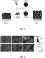
Fig. 2 is a schematic representation comparing prior art high dispersity particle sizes (left), which lead to undefined electrode structures, to low dispersity particle sizes according to the present invention (right), which enable the production of defined and reproducible porous catalyst layers; -
Fig. 3 shows SEM images of carbon support materials in SE (secondary electron) mode of the prior art (a, b, c) and according to the present invention (e, f, g), with the respective particle size distributions shown (d, h); -
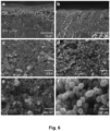
Fig. 4 shows results of nitrogen physisorption measurements at 77 K of the prior art and according to the present invention on a 3P Instruments machine with (a) isotherms, (b) calculated pore size distribution via a QSDFT model, and (c) the BET surface area of Ketjenblack and MPNC-7-130 with 785 and 876 m2g-1, respectively; -
Fig. 5 shows XRD (b) on a Bruker D8 Discover of the prior art and according to the present invention, and SEM images of the prior art (c, d, g, h) and the present invention (a, e, f, I, j) in both SE (secondary electron) mode and TE (transmission electron mode); -
Fig. 6 shows SEM images of the coatings prepared from the electrocatalyst material-based inks of the prior art (a, c, e) and according to the present invention (b, d, f); -
Fig. 7 shows polarization curves (a), mass activity (b), electrochemical surface area (ECSA) (c) and peak power density (d) of the prior art and according to the present invention. - It is understood that the following description and references to the figures concern exemplary embodiments of the present invention and shall not be limiting the scope of the claims.
- For a better understanding of the invention, the following explanations of the terminology used herein are considered useful. In the context of the present invention, the following definitions apply:
- "Porous catalyst layer" as used in the present application means a percolated structure suitable for use in a catalyst coated membrane. For example, a porous catalyst layer may comprise a supported metal catalyst for enhancing reaction rates and electronic conduction, an ionomer for ion conduction, and voids for reactant gas and water transport.
- "Porous carbon structure" as used in the present application means a structure comprising a solid stable assembly of percolated carbon particles, wherein individual assembled carbon particles are specifically arranged in space with respect to each other, and wherein voids between individual carbon particles form an interparticular porosity. As used herein, porous carbon structures may comprise additional species besides the percolated carbon particles, such as heteroatoms, doping agents, additives, binders, and other species.
- "Particle diameter", also referred to as particle size, indicates the spatial extent of a single particle. Particle diameters are determined by counting out the particle diameters on electron micrographs obtained by scanning (transmission) electron microscopy with a sufficient large number of particles (at least 200 particles). Non-spherical particles (for example elliptical particles) are described by their minimum and maximum diameter.
- "Particle-diameter dispersity Ð ("D stroke") is based on the IUPAC definition of dispersity given in Pure Appl. Chem., Vol. 83, No. 12, pp. 2251-2259, 2011. Particle diameter dispersity Ð measures the width of a particle-diameter distribution and is given by

- "Pore size" (pore width) means the distance between two opposite walls of the pore. According to IUPAC nomenclature (Pure & Appl. Chem. Vol. 66, No. 8, pp. 1739-1758, 1994) micropores have width smaller than 2 nm, mesopores have width between 2 and 50 nm, macropores have widths larger than 50 nm.
- "Templated pore size" means the diameter of a spherical template employed for the pore formation in spherical porous carbon particles as used in the present invention. Polymerisation of a carbon precursor in the presence of nanometer-sized spherical templates leads to the formation of carbon-template composites. Removal of the template material leaves nanometer-sized pores within the polymeric carbon structures. The pores may be interconnected, and therefore the pores will not exclusively have spherical shapes, but they may take the shape of juxtaposed spheres with varying intersectional diameters. Therefore, "templated pore size" may differ from measured pore size, and the templated pore size dispersity may differ from the measured pore size dispersity. The templated pore size dispersity Ð' corresponds to the particle diameter dispersity of the templates employed to form the pores.
- "Nanoparticle" means a particle of any shape with dimensions in the 1 nm to 100 nm range. Tubes and fibers with only two dimensions below 100 nm are also nanoparticles (see Pure Appl. Chem., 84, 2, 377 - 410).
- The present invention according to the appended claims provides metal nanoparticle loaded low dispersity porous carbon particles with adjustable particle and pore sizes for building 3D-percolated catalyst layers based thereon, in which the interparticle porosity is defined by the arrangement of the metal nanoparticle loaded low dispersity spherical carbon particles, and the intraparticle porosity is defined by the intraparticle porosity of the metal nanoparticle loaded low dispersity spherical carbon particles.
- Prior to the conception of the present invention, such an approach did not exist in the field of MEA or CCM or GDE production for fuel cells and electrolysers, because there were hardly any scaled and commercial metal nanoparticle loaded low dispersity porous carbon particles available, in which the carbon particle size and pore size could be adjusted to build up the catalyst layers according to the present invention. Building a controllable hierarchical 3D porosity in catalyst layers with state-of-the-art particles was thus not possible.
- As shown in
Fig. 2 , high dispersity carbon particles lead to irregular and non-reproducible active electrodes, whereas low dispersity carbon particles lead to regular and reproducible active electrodes. According to the prior art, a highly defined structuring of catalyst layers was not possible for carbon supports. The present invention allows access to controllable metal nanoparticle loaded porous catalyst layers that can increase power density or hydrogen productivity in the field of fuel cells and electrolysers by improving mass transport. Based on the optimised interparticle and intraparticle porosity within the catalyst layer, the entire electrode becomes electrochemically accessible, which is not necessarily the case with conventional unstructured electrodes. This leads to better performance of the 3D-structured electrode with the same amount of the active expensive catalyst material, or, alternatively, allows the reduction of the expensive active catalyst metal with the same performance. - Furthermore, the reproducibility of the electrode is improved, as metal nanoparticle loaded low dispersity spherical carbon particles or carbon supports are used to build 3D-structured electrodes. The morphological properties of the catalyst layer ultimately depend heavily on the morphological properties of the low dispersity carbon particle (adjustable templated pore size and spherical particle size, dispersity). Further adjustable properties of the low dispersity carbon particles, i.e. the microstructuring of the carbon particles, enable further adjustment possibilities of the electrode, such as conductivity, wettability, corrosion resistance. In fuel cell catalysis as detailed in the exemplary section, the metal nanoparticle loaded 3D-porous catalyst layers of metal nanoparticle loaded monodisperse porous carbon particles show the improvements in mass transport and catalysis to a state-of-the-art Pt loaded carbon material. Here, the catalytically active species is kept the same on both support systems to study the effect of the support.
- It should be noted that the present invention may comprise any combination of the features and/or limitations referred to herein, except for combinations of such features which are mutually exclusive. The foregoing description is directed to particular embodiments of the present invention for the purpose of illustrating it. It will be apparent, however, to one skilled in the art, that many modifications and variations to the embodiments described herein are possible. All such modifications and variations are intended to be within the scope of the present invention, as defined in the appended claims.
- An electrocatalyst is composed of a carbon support and platinum in which the carbon supports are Ketjenblack® EC300J (KB) and mesoporous N-doped carbon (MPNC) nanospheres. KB was purchased from Nouryon whereas MPNC was synthesized based on a previous report (see Example 1 below). The active material used in this exemplary embodiment are Pt nanoparticles. The synthesis reactants H2PtCl6 6H2O (Grade: Premion) and ethylene glycol (≥ 99%) were purchased from AlfaAesar and Sigma-Aldrich, respectively. For the electrode ink, isopropanol (≥ 99,5%) and 800EW ionomer were purchased from Carl Roth and 3M, repectively. A Fumatech fumapem® FS715RFS, 715 EW, 15 µm membrane and a Freudenberg H14Cx GDL were used for fuel cell tests. For the anode side of fuel cell tests, a Pt based catalyst TEC10E50E (TKK) was purchased from Tanaka Kikinzoku Kogyo. O2, H2 and N2 with a gas purity of 99.999% were purchased from Sauerstoffinierke Friedrichshafen.
- The synthesis of MPNC nanospheres has been reported previously by Melke et al. in "Electrochemical stability of silica-templated polyaniline-derived mesoporous N-doped carbons for the design of Pt-based oxygen reduction reaction catalysts (Carbon 146, 2019, 44 - 59; https://doi.org/10.1016/j.carbon.2019.01.057) and in "Investigating the Effect of Microstructure and Surface Functionalization of Mesoporous N-Doped Carbons on V4+/V5+ Kinetics (ACS Appl. Energy Mater. 2020, 3, 12, 11627 - 11640; https://dx.doi.org/10.1021/acsaem.0c01489). Aniline is polymerized in an oxidative polymerisation in the presence of nanosized SiO2 particles, in order to form a polymer-SiO2 composite. Then, the polymer-SiO2 composite is carbonized at 1000°C under N2, the template is removed by chemical etching and the sample is washed. A final heat-treatment step at 500°C under inert atmosphere is applied.
-
Fig. 3 shows SEM images of the carbon support materials in SE (secondary electron) mode of (a, b, c) KB and of (e, f, g) MPNC-7-130. SEM image measurements were carried out using a Field Emission Gun High Resolution SEM SU8220 (Hitachi). The particle size distributions of (d) KB and (h) MPNC-7-130 were determined using multiple images recorded with a magnification of 200kx and 50kx, respectively. -
Fig. 4 shows nitrogen physisorption measurements at 77 K of KB and MPNC-7-130 on a 3P Instruments machine with (a) isotherms and (b) calculated pore size distribution via a quenched solid density functional theory model (QSDFT adsorption branch of N2 at 77 K on carbon, taking into account slit/spherical/cylindrical pores). The measurements clearly show the defined mesoporosity of the MPNC sample. Part (c) shows the surface area (BET, Brunauer-Emmett-Teller) of KB and MPNC-7-130 with 785 and 876 m2g-1, respectively. - The synthesis of Pt nanoparticles on KB and low dispersity MPNC nanospheres with a templated pore size of 7 nm, a mean particle size of 126 nm and carbonized at 1000°C (MPNC-7-130) is based on a state-of-the-art ethylene glycol route: 350 mg carbon support was dispersed in 200 ml ethylene glycol and homogenized by vigorous stirring. H2PtCl6 6H2O was dissolved in 100 ml water and subsequently added to the carbon suspension. Thereby, a specific amount of Pt precursors was used to obtain a Pt mass loading of 40 wt.-%, based on the total mass of Pt and carbon. The suspension was stirred at 120°C for 2 h and cooled to room temperature for 1 h. Finally, the samples were washed with boiling water until the supernatant was neutral and dried under vacuum at 80°C.
-
Fig. 5 shows a low-magnification SEM image (a) of Pt/MPNC-7-130, and XRD (b) on a Bruker D8 Discover of electrocatalysts Pt/KB and Pt/MPNC-7-130 revealing the same XRD pattern and hence same Pt crystallite size (2.3 nm by Scherrer equation), as well as SEM images of electrocatalysts Pt/KB (in SE (secondary electron) mode c, g and TE (transmission electron) mode d, h) and Pt/MPNC-7-130 (in SE mode e, i and TE mode f, j). SEM image measurements were carried out using a Field Emission Gun High Resolution SEM SU8220 (Hitachi) equipped with a SE and TE detector. - The electrode active material was used as cathode electrocatalyst and deposited on a PEM. 100 mg of electrocatalyst was homogenized in 4.97 g of DI-water, 1.24 g of isopropanol and 0.77 g of ionomer dispersion (5 wt.-% in isopropanol), resulting in an I/C weight ratio of 0.65. The ink was placed in an ice-bath and mixed for 60 minutes with a tip sonicator (Hielscher UIS250L) at 480W. The dispersed ink was loaded into a spray coater (Sonaer Sono-Cell) and sprayed centrally through an N2 driven 60 kHz nozzle onto the membrane (5 × 5 cm), which was placed on an 80°C hot plate. A 2 × 2 cm mask was applied to obtain a defined cell area of 4 cm2. The targeted cathode mass loading of 0.4 mg Pt/cm2 was determined gravimetrically and by micro-X-ray fluorescence (M4 Tornado of Bruker Nano GmbH).
- For the ink of the anode side, 400 mg of TKK, with 19.89 g of DI water, 4.97 g of isopropanol and 3.11 g of ionomer dispersion (5 wt.-% in isopropanol) were homogenized and sprayed onto the other side of the membrane by the same process. However, the loading of the anode was set to 0.1 mg Pt/cm2. GDLs and a PTFE gaskets (thickness 130 µm) were applied to each of the two electrodes in order to ensure homogenous gas distribution and avoid gas leakage, respectively. The resulting MEA was clamped between a meander-type flow field and a fuel cell fixture (5 Nm, Scribner Associates).
- The electrochemical characterization of the porous catalyst layers, implemented in a CCM/MEA was performed on a test bench (Scribner Associates, Model 850e). The test protocol can be found in the following Table 1:
Table 1. Applied fuel cell test protocol Protocol sequence Operating conditions 1. Conditioning (Break-in) 60 cycles between 0.2 V and 0.5 V for 30 s each, 80°C, 96% r.H., 100 kPaabs 2. Polarization curve under O2/H2 UI-curve Anode: 0.25 l/min H2, Cathode: 0.50 l/ min 100% O2, 80°C, 96% r.H., 100 kPaabs, galvanostatic3. Voltage recovery Anode: 0.25 l/min H2, Cathode: 1.00 l/min 21% O2, 55°C, 100% r.H., 100 kPaabs, 180 cycles between 0.08 and 0.12, 20 s each 4. Polarization curve under O2/H2 (Determination of mass activity) UI-curve Anode: 0.25 l/min H2, Cathode: 0.50 l/ min 100% O2, 80°C, 96% r.H., 100 kPaabs, galvanostatic5. Polarization curve under Air (21% O2)/H2 UI-curve Anode: 0.25 l/min H2, Cathode: 0.50 l/min 21% O2, 80°C, 50% r.H., 100 kPaabs, galvanostatic 6. Cyclic voltammetry (Determination of ECSA*) Anode: 0.20 l/min H2, Cathode: no flow, 35°C, 96% r.H., scan rate: 50 mV/s, range: 0.05 - 0.80 V 7. Liner sweep voltammetry (Determination of cross-over current Ic) Anode: 0.20 l/min H2, Cathode: 0.05 l/min N2, 35°C, 96% r.H., scan rate: 1 mV/s, range: 0.00 - 0.60 V *ECSA = electrochemical active surface area - After the conditioning of the MEA (step 1) and activation in O2 (Steps 2 and 3), a polarization curve in O2 (step 4) was used to study the cathodic kinetics (mass activity) of the porous catalyst layer. The mass activity in A/gPt was calculated by dividing the current at 0.9 V by the Pt mass on the cathode side. Thereby the currents were corrected by ohmic losses and the cross-over current Ic (step 7). The polarization curve step 5 applied lower relative humidities under air representing more realistic fuel cell conditions. Finally, cyclic voltammograms (step 6) were recorded to calculate the ECSA in m2/gpt by integrating the Ic corrected charge of hydrogen underpotential deposition and normalizing it to 210 µC/cm2, which corresponds to a polycrystalline Pt surface covered with the theoretically maximum amount of hydrogen. The power density of the MEA is calculated by multiplying the applied current with the measured cell potential.
- The results are shown in
Fig. 7 . Polarization curves (a) of porous catalyst layer material under the following conditions: Anode: 0.25 l/min H2, Cathode: 0.50 l/min 21% O2, 80°C, 50% r.H., 100 kPaabs. Pt/MPNC-7-130 shows increased voltages over the entire current density region than a Pt/KB electrocatalyst based on a prior art carbon support with same Pt loading and particle size. Mass activity is shown in (b). ECSA is shown in (c). Peak power density is shown in (d). These reveal increased performance indicators of novel Pt/MPNC-7-130 based porous catalyst layer in all categories. The MEAs that use Pt/MPNC-7-130 instead of Pt/KB at the cathode show a higher performance in the activity range (0.9 V), which may be due to an improved ionomer distribution/connection. Higher performance is also seen in the high current density range, which may be due to better mass transport in the catalyst layer. Thus, electrodes based on Pt/MPNC-based catalysts or based on MPNC carbon supports show improved performance over the Pt/KB prior art.
Claims (13)
- Porous catalyst layer comprising a metal nanoparticle loaded porous carbon structure, wherein the said porous carbon structure is assembled from porous spherical carbon particles with a particle size dispersity (Ð) of 1.2 or less, and with a templated pore size with a templated pore size dispersity (Ð') of 1.2 or less.
- Porous catalyst layer according to claim 1, wherein the said porous spherical carbon particles have particle diameters of 10 nm to 5000 nm, preferably of 25 nm to 2500 nm or of 50 nm to 500 nm, and wherein the templated pore sizes are from 1 nm to 1000 nm, preferably from 2 nm to 500 nm or from 5 nm to 100 nm.
- Porous catalyst layer according to claim 1 or 2, wherein the porous carbon structure has a metal nanoparticle loading of 1 to 95 wt.-%, such as for example 5 to 90 wt. %, or 10 to 85 wt. %, or 15 to 80 wt. %, or 20 to 75 wt. %, or 25 to 70 wt. %, or 30 to 65 wt. %, or 35 to 60 wt. %, or 40 to 55 wt. %, or 45 to 50 wt. %, based on the total weight of the metal nanoparticle loaded porous carbon structure.
- Porous catalyst layer according to any one of claims 1 to 3, wherein the metal is a metal selected from the Groups 1, 2, 12, 13, 14, 15, or 16 of the Periodic table of the elements, or a transition metal selected from the Groups 3, 4, 5, 6, 7, 8, 9, 10, 11, or 12 of the Periodic table of the elements, or a metal from the lanthanide of actinide series, or a metalloid from the Groups 13, 14, 15, 16, or 17 of the Periodic table of the elements, or wherein the metal is an alloy of any two or more metal and/or metalloid elements as defined above.
- Porous catalyst layer according to any one of claims 1 to 4, wherein the metal nanoparticles have a diameter in any dimension of no more than 100 nm, for example from 1 nm to 75 nm, or from 2 nm to 60 nm, or from 3 nm to 40 nm, or from 4 nm to 25 nm, or from 5 nm to 20 nm, or from 7 nm to 15 nm, or from 8 nm to 10 nm.
- Porous catalyst layer according to any one of claims 1 to 5, wherein the porous carbon structure has an interparticle pore volume is from 15% to 60%, for example from 20% to 55%, or from 25% to 50%, or preferably from 26% to 48%.
- Porous catalyst layer according to any one of claims 1 to 6, wherein a ratio of intraparticle pore volume to interparticle pore volume is from 0.05 to 3.0, preferably from 0.1 to 2.0, more preferably from 0.7 to 1.9.
- Porous catalyst layer according to any one of claims 1 to 7, wherein the particle size dispersity (Ð) of the porous spherical carbon particles and/or the templated pore size dispersity (Ð') of the porous spherical carbon particles is 1.1 or less.
- Method of production for the porous catalyst layer of any one of the previous claims, comprising the steps of(i) providing low dispersity porous spherical carbon particles as defined in any one of claims 1 to 8, loaded with metal nanoparticles;(ii) mixing the provided metal nanoparticle loaded porous spherical carbon particles with one or more additives;(iii) applying the obtained mixture onto a substrate to form a layer of metal nanoparticle loaded porous carbon structure;(iv) drying and/or curing the applied mixture to form a dry layer of metal nanoparticle loaded porous carbon structure; and(v) optional calendering of the dry layer of metal nanoparticle loaded porous carbon structure.
- Method of production according to claim 9, wherein the mixing step (ii) includes addition of a dispersion medium to form an ink or a paste, and wherein step (iii) is carried out by 3D-printing, slot-die coating, ink-jet printing, doctor-blading, spray coating, spin-coating or dip-coating.
- Membrane electrode assembly comprising one or more catalyst layers consisting of or comprising a metal nanoparticle loaded porous carbon structure of any one of claims 1 to 8.
- Membrane electrode assembly according to claim 11, wherein the one or more catalyst layers include one or more binders such as for example polymeric binders and/or ionomers.
- Use of a porous catalyst layer of any one of claims 1 to 8 or of a membrane electrode assembly of any one of claims 11 or 12 in an electrochemical energy conversion device such as a PEM/AEM fuel cell or a PEM/AEM electrolyser.
Priority Applications (2)
| Application Number | Priority Date | Filing Date | Title |
|---|---|---|---|
| EP23207554.9A EP4550481A1 (en) | 2023-11-02 | 2023-11-02 | Porous catalyst layer made of low dispersity porous spherical carbon particles and metal nanoparticles supported thereon, membrane-electrode assemblies made therefrom and their use |
| PCT/EP2024/080894 WO2025093714A1 (en) | 2023-11-02 | 2024-10-31 | Porous catalyst layer made of low dispersity porous spherical carbon particles and metal nanoparticles supported thereon, membrane-electrode assemblies made therefrom and their use |
Applications Claiming Priority (1)
| Application Number | Priority Date | Filing Date | Title |
|---|---|---|---|
| EP23207554.9A EP4550481A1 (en) | 2023-11-02 | 2023-11-02 | Porous catalyst layer made of low dispersity porous spherical carbon particles and metal nanoparticles supported thereon, membrane-electrode assemblies made therefrom and their use |
Publications (1)
| Publication Number | Publication Date |
|---|---|
| EP4550481A1 true EP4550481A1 (en) | 2025-05-07 |
Family
ID=88690315
Family Applications (1)
| Application Number | Title | Priority Date | Filing Date |
|---|---|---|---|
| EP23207554.9A Pending EP4550481A1 (en) | 2023-11-02 | 2023-11-02 | Porous catalyst layer made of low dispersity porous spherical carbon particles and metal nanoparticles supported thereon, membrane-electrode assemblies made therefrom and their use |
Country Status (2)
| Country | Link |
|---|---|
| EP (1) | EP4550481A1 (en) |
| WO (1) | WO2025093714A1 (en) |
Citations (1)
| Publication number | Priority date | Publication date | Assignee | Title |
|---|---|---|---|---|
| EP3828133A1 (en) | 2019-11-29 | 2021-06-02 | Toyota Jidosha Kabushiki Kaisha | Mesoporous carbon and manufacturing method of the same, and polymer electrolyte fuel cell |
-
2023
- 2023-11-02 EP EP23207554.9A patent/EP4550481A1/en active Pending
-
2024
- 2024-10-31 WO PCT/EP2024/080894 patent/WO2025093714A1/en active Pending
Patent Citations (1)
| Publication number | Priority date | Publication date | Assignee | Title |
|---|---|---|---|---|
| EP3828133A1 (en) | 2019-11-29 | 2021-06-02 | Toyota Jidosha Kabushiki Kaisha | Mesoporous carbon and manufacturing method of the same, and polymer electrolyte fuel cell |
Non-Patent Citations (14)
| Title |
|---|
| "Investigating the Effect of Microstructure and Surface Functionalization of Mesoporous N-Doped Carbons on V4+/V5+ Kinetics", ACS APPL. ENERGY MATER, vol. 3, no. 12, 2020, pages 11627 - 11640, Retrieved from the Internet <URL:https://dx.doi.org/10.1021/acsaem.Oc01489> |
| "Particle-diameter dispersity fl (''D stroke'') is based on the IUPAC definition of dispersity given", PURE APPL. CHEM, vol. 83, no. 12, 2011, pages 2251 - 2259 |
| CHOI ET AL.: "Single-Step Fabrication of a Multiscale Porous Catalyst Layer by the Emulsion Template Method for Low Pt-Loaded Proton Exchange Membrane Fuel Cells", ACS APPL. ENERGY MATER, vol. 4, no. 4, 2021, pages 4012 - 4020 |
| JOO ET AL.: "Preparation of mesoporous carbon templated by silica particles for use as a catalyst support in polymer electrolyte membrane fuel cells", CATALYSIS TODAY, vol. 111, 2006, pages 171 - 175, XP025116726, DOI: 10.1016/j.cattod.2005.10.021 |
| LIU ET AL.: "Effect of Catalyst Ink and Formation Process on the Multiscale Structure of Catalyst Layers in PEM Fuel Cells", APPL. SC, vol. 12, 2022, pages 3776, Retrieved from the Internet <URL:https://www.mdpi.com/2076-3417/12/8/3776> |
| MELKE ET AL.: "Electrochemical stability of silica-templated polyaniline-derived mesoporous N-doped carbons for the design of Pt-based oxygen reduction reaction catalysts", CARBON, vol. 146, 2019, pages 44 - 59, Retrieved from the Internet <URL:https://doi.org/10.1016/j.carbon.2019.01.057> |
| MELKE JULIA ET AL: "Electrochemical stability of silica-templated polyaniline-derived mesoporous N-doped carbons for the design of Pt-based oxygen reduction reaction catalysts", CARBON, vol. 146, 19 January 2019 (2019-01-19), GB, pages 44 - 59, XP093142882, ISSN: 0008-6223, DOI: 10.1016/j.carbon.2019.01.057 * |
| MELKE JULIA ET AL: "Investigating the Effect of Microstructure and Surface Functionalization of Mesoporous N-Doped Carbons on V 4+ /V 5+ Kinetics", ACS APPLIED ENERGY MATERIALS, vol. 3, no. 12, 18 November 2020 (2020-11-18), pages 11627 - 11640, XP093142796, ISSN: 2574-0962, DOI: 10.1021/acsaem.0c01489 * |
| PURE & APPL. CHEM, vol. 66, no. 8, 1994, pages 1739 - 1758 |
| PURE APPL. CHEM, vol. 84, no. 2, pages 377 - 410 |
| SHU ET AL.: "Hierarchically mesoporous carbon spheres coated with a single atomic Fe-N-C layer for balancing activity and mass transfer in fuel cells", CARBON ENERGY, vol. 4, 2022, pages 1 - 11 |
| SUTER: "Engineering Catalyst Layers for Next-Generation Polymer Electrolyte Fuel Cells: A Review of Design, Materials, and Methods", ADV. ENERGY MATTER, vol. 11, 2021, pages 2101025, Retrieved from the Internet <URL:https://doi.org/10.1002/aenm.202101025> |
| WANG ET AL.: "Achievements, challenges and perspectives on cathode catalysts in proton exchange membrane fuel cells for transportation", NATURE CATALYSIS, vol. 2, 2019, pages 578 - 589, Retrieved from the Internet <URL:https://doi.rg/10.1038/41929-019-0304-9> |
| WANG ET AL.: "Controlled Synthesis of N-Doped Carbon Nanospheres with Tailored Mesopores through Self-Assembly of Colloidal Silica", ANGEW. CHEM. INT. ED, vol. 54, 2015, pages 15191 - 15196 |
Also Published As
| Publication number | Publication date |
|---|---|
| WO2025093714A1 (en) | 2025-05-08 |
Similar Documents
| Publication | Publication Date | Title |
|---|---|---|
| US11271219B2 (en) | Electrode catalyst, composition for forming gas diffusion electrode, gas diffusion electrode, membrane electrode assembly and fuel cell stack | |
| CN104094460B (en) | Electrode catalyst layer for fuel cell | |
| EP3446781B1 (en) | Electrocatalyst, membrane electrode assembly using said electrocatalyst, and fuel cell | |
| CA2925618C (en) | Carbon powder for catalyst, catalyst, electrode catalyst layer, membrane electrode assembly, and fuel cell using the carbon powder | |
| US8309276B2 (en) | Process for preparing of a catalyst solution for fuel cell and a membrane electrode assembly using the same | |
| Wei et al. | High performance polymer electrolyte membrane fuel cells (PEMFCs) with gradient Pt nanowire cathodes prepared by decal transfer method | |
| EP3567665A1 (en) | Catalyst layer for fuel cell and production method therefor | |
| EP3648213A1 (en) | Solid polymer-type fuel cell catalyst carrier, method for manufacturing solid polymer-type fuel cell catalyst carrier, catalyst layer for solid polymer-type fuel cell, and fuel cell | |
| Jayawickrama et al. | Enhanced platinum utilization efficiency of polymer-coated carbon black as an electrocatalyst in polymer electrolyte membrane fuel cells | |
| Su et al. | Ionomer content effects on the electrocatalyst layer with in-situ grown Pt nanowires in PEMFCs | |
| Bandapati et al. | Platinum utilization in proton exchange membrane fuel cell and direct methanol fuel cell | |
| Zhao et al. | Highly active carbon nanotube-supported Pd electrocatalyst for oxidation of formic acid prepared by etching copper template method | |
| US11217796B2 (en) | Electrode catalyst for fuel cell and method of production of same | |
| EP3416221B1 (en) | Method for preparing membrane-electrode assembly | |
| Sevjidsuren et al. | Effect of different support morphologies and Pt particle sizes in electrocatalysts for fuel cell applications | |
| Sepp et al. | Enhanced stability of symmetrical polymer electrolyte membrane fuel cell single cells based on novel hierarchical microporous-mesoporous carbon supports | |
| KR101982744B1 (en) | Catalyst for fuel cell and method of manufacturing the same, and membrane-electrode assmbly and method of manufacturing the same | |
| WO2025093714A1 (en) | Porous catalyst layer made of low dispersity porous spherical carbon particles and metal nanoparticles supported thereon, membrane-electrode assemblies made therefrom and their use | |
| EP4549383A1 (en) | Low dispersity porous spherical carbon particles with active material supported thereon, porous layers made therefrom, their preparation and their use | |
| Pedram et al. | Microscopy studies of the catalyst inks for pem fuel cells | |
| Sepp et al. | Activity and stability of carbide derived carbon supports in PEMFC application | |
| Vaarmets et al. | Accelerated durability tests for Pt-nanoclusters modified carbide derived carbons catalysts in acidic solution | |
| KR102554270B1 (en) | Nanoparticle 3D structure deposition method using electrophoretic deposition method and electrode for hydrogen evolution reaction prepared thereby | |
| Chang et al. | Rambutan-like CNT-Al2O3 scaffolds for high-performance cathode catalyst layers of polymer electrolyte fuel cells | |
| JP2005190712A (en) | Catalyst-supporting electrode, MEA for fuel cell and fuel cell |
Legal Events
| Date | Code | Title | Description |
|---|---|---|---|
| PUAI | Public reference made under article 153(3) epc to a published international application that has entered the european phase |
Free format text: ORIGINAL CODE: 0009012 |
|
| STAA | Information on the status of an ep patent application or granted ep patent |
Free format text: STATUS: THE APPLICATION HAS BEEN PUBLISHED |
|
| AK | Designated contracting states |
Kind code of ref document: A1 Designated state(s): AL AT BE BG CH CY CZ DE DK EE ES FI FR GB GR HR HU IE IS IT LI LT LU LV MC ME MK MT NL NO PL PT RO RS SE SI SK SM TR |
|
| STAA | Information on the status of an ep patent application or granted ep patent |
Free format text: STATUS: REQUEST FOR EXAMINATION WAS MADE |
|
| 17P | Request for examination filed |
Effective date: 20251107 |