EP4550410A1 - Unit - Google Patents
Unit Download PDFInfo
- Publication number
- EP4550410A1 EP4550410A1 EP23830910.8A EP23830910A EP4550410A1 EP 4550410 A1 EP4550410 A1 EP 4550410A1 EP 23830910 A EP23830910 A EP 23830910A EP 4550410 A1 EP4550410 A1 EP 4550410A1
- Authority
- EP
- European Patent Office
- Prior art keywords
- cooler
- coolant
- fiber bodies
- fiber
- coolant water
- Prior art date
- Legal status (The legal status is an assumption and is not a legal conclusion. Google has not performed a legal analysis and makes no representation as to the accuracy of the status listed.)
- Withdrawn
Links
Images


Classifications
-
- H—ELECTRICITY
- H05—ELECTRIC TECHNIQUES NOT OTHERWISE PROVIDED FOR
- H05K—PRINTED CIRCUITS; CASINGS OR CONSTRUCTIONAL DETAILS OF ELECTRIC APPARATUS; MANUFACTURE OF ASSEMBLAGES OF ELECTRICAL COMPONENTS
- H05K7/00—Constructional details common to different types of electric apparatus
- H05K7/20—Modifications to facilitate cooling, ventilating, or heating
- H05K7/2089—Modifications to facilitate cooling, ventilating, or heating for power electronics, e.g. for inverters for controlling motor
- H05K7/20927—Liquid coolant without phase change
-
- H—ELECTRICITY
- H05—ELECTRIC TECHNIQUES NOT OTHERWISE PROVIDED FOR
- H05K—PRINTED CIRCUITS; CASINGS OR CONSTRUCTIONAL DETAILS OF ELECTRIC APPARATUS; MANUFACTURE OF ASSEMBLAGES OF ELECTRICAL COMPONENTS
- H05K7/00—Constructional details common to different types of electric apparatus
- H05K7/20—Modifications to facilitate cooling, ventilating, or heating
- H05K7/20218—Modifications to facilitate cooling, ventilating, or heating using a liquid coolant without phase change in electronic enclosures
- H05K7/20254—Cold plates transferring heat from heat source to coolant
-
- H—ELECTRICITY
- H10—SEMICONDUCTOR DEVICES; ELECTRIC SOLID-STATE DEVICES NOT OTHERWISE PROVIDED FOR
- H10W—GENERIC PACKAGES, INTERCONNECTIONS, CONNECTORS OR OTHER CONSTRUCTIONAL DETAILS OF DEVICES COVERED BY CLASS H10
- H10W40/00—Arrangements for thermal protection or thermal control
- H10W40/40—Arrangements for thermal protection or thermal control involving heat exchange by flowing fluids
- H10W40/47—Arrangements for thermal protection or thermal control involving heat exchange by flowing fluids by flowing liquids, e.g. forced water cooling
-
- B—PERFORMING OPERATIONS; TRANSPORTING
- B60—VEHICLES IN GENERAL
- B60R—VEHICLES, VEHICLE FITTINGS, OR VEHICLE PARTS, NOT OTHERWISE PROVIDED FOR
- B60R16/00—Electric or fluid circuits specially adapted for vehicles and not otherwise provided for; Arrangement of elements of electric or fluid circuits specially adapted for vehicles and not otherwise provided for
- B60R16/02—Electric or fluid circuits specially adapted for vehicles and not otherwise provided for; Arrangement of elements of electric or fluid circuits specially adapted for vehicles and not otherwise provided for electric constitutive elements
- B60R16/03—Electric or fluid circuits specially adapted for vehicles and not otherwise provided for; Arrangement of elements of electric or fluid circuits specially adapted for vehicles and not otherwise provided for electric constitutive elements for supply of electrical power to vehicle subsystems or for
Definitions
- the present invention relates to a unit.
- Patent Document 1 discloses a cooling member in which metal fibers are filled in an accommodating body and cooling is performed using a high thermal conductivity of the metal fibers.
- Patent Document 1 JP 2019-009433 A
- An object of the present invention is to provide a novel structure of a use form of a fiber body based on the above concepts.
- a unit includes an electric circuit unit, a cooler through which a coolant passes, and a fiber body, the electric circuit unit is cooled by the cooler, and the fiber body has a portion disposed at a coolant inlet of the cooler.
- turbulence is generated in a cooler, and the cooling efficiency of an electric circuit unit through the coolant can be improved by providing a fiber body at a coolant inlet. Accordingly, it is possible to provide a novel structure of a use form of a fiber body.
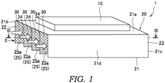
- FIG. 1 is a perspective view of the water-cooled electric circuit unit 1.
- FIG. 2 is a view taken along an arrow II in FIG. 1 .
- FIG. 3 is a cross-sectional view taken along a line III-III in FIG. 1 .
- the power module 10 includes a plurality of switching elements (not shown) such as an insulated gate bipolar transistor (IGBT) constituting an inverter circuit that controls a rotating electrical machine (not shown) serving as a drive source of a vehicle.
- the power module 10 is in contact with the cooler 20 and is cooled by the cooler 20.
- the contact is a concept including not only direct contact but also indirect contact (thermal contact) with a metal plate or the like having high thermal conductivity interposed therebetween.
- the cooler 20 cools the power module 10 that generates heat during operation.
- coolant water as a coolant for cooling the power module 10 passes.
- the coolant is not limited to the coolant water, and may be another liquid such as coolant oil.
- the cooler 20 includes a main body 21, inlets 22 as a coolant inlet, outlets 23 as a coolant outlet, and a plurality of partition plates 24.
- the main body 21 is formed in a substantially rectangular parallelepiped shape.
- the main body 21 includes a top surface 21a and four side surfaces 21b, 21c, 21d, and 21e (see FIG. 3 ).
- a coolant water passage 25 serving as a coolant passage is defined in the main body 21.
Landscapes
- Engineering & Computer Science (AREA)
- Microelectronics & Electronic Packaging (AREA)
- Physics & Mathematics (AREA)
- Thermal Sciences (AREA)
- Cooling Or The Like Of Semiconductors Or Solid State Devices (AREA)
- Cooling Or The Like Of Electrical Apparatus (AREA)
Abstract
Description
- The present invention relates to a unit.
-
Patent Document 1 discloses a cooling member in which metal fibers are filled in an accommodating body and cooling is performed using a high thermal conductivity of the metal fibers. - Patent Document 1:
JP 2019-009433 A - As a result of diligent studies, the present inventors have found that when a coolant passes through fibers, turbulence is generated, and cooling is promoted by an effect of the turbulence. Furthermore, it has been found that when the coolant passes through a surface of the fibers, turbulence is generated due to disorder of the surface of the fibers, and the cooling is promoted by an effect of the turbulence. According to the findings, it means that the cooling performance can be enhanced regardless of the material of a fiber body, and the fiber body can be used in a form completely different from concepts described in
Patent Document 1. - An object of the present invention is to provide a novel structure of a use form of a fiber body based on the above concepts.
- According to an aspect of the present invention, a unit includes an electric circuit unit, a cooler through which a coolant passes, and a fiber body, the electric circuit unit is cooled by the cooler, and the fiber body has a portion disposed at a coolant inlet of the cooler.
- According to an aspect of the present invention, turbulence is generated in a cooler, and the cooling efficiency of an electric circuit unit through the coolant can be improved by providing a fiber body at a coolant inlet. Accordingly, it is possible to provide a novel structure of a use form of a fiber body.
-
- [
FIG. 1] FIG. 1 is a perspective view of a unit according to an embodiment of the present invention. - [
FIG. 2] FIG. 2 is a view taken along an arrow II inFIG. 1 . - [
FIG. 3] FIG. 3 is a cross-sectional view taken along a line III-III inFIG. 1 . - [
FIG. 4] FIG. 4 is a perspective view of a unit according to a modification of the embodiment of the present invention. - [
FIG. 5] FIG. 5 is a view taken along an arrow V inFIG. 4 . - [
FIG. 6] FIG. 6 is a cross-sectional view taken along a line VI-VI inFIG. 4 . - Hereinafter, a water-cooled
electric circuit unit 1 as a unit according to an embodiment of the present invention will be described with reference to the drawings. - First, the water-cooled
electric circuit unit 1 will be described with reference toFIGS. 1 to 3 . -
FIG. 1 is a perspective view of the water-cooledelectric circuit unit 1.FIG. 2 is a view taken along an arrow II inFIG. 1 .FIG. 3 is a cross-sectional view taken along a line III-III inFIG. 1 . - As shown in
FIG. 1 , the water-cooledelectric circuit unit 1 includes apower module 10 as an electric circuit unit, acooler 20, andfiber bodies 30. - The
power module 10 includes a plurality of switching elements (not shown) such as an insulated gate bipolar transistor (IGBT) constituting an inverter circuit that controls a rotating electrical machine (not shown) serving as a drive source of a vehicle. Thepower module 10 is in contact with thecooler 20 and is cooled by the cooler 20. The contact is a concept including not only direct contact but also indirect contact (thermal contact) with a metal plate or the like having high thermal conductivity interposed therebetween. - The
cooler 20 cools thepower module 10 that generates heat during operation. In the cooler 20, coolant water as a coolant for cooling thepower module 10 passes. The coolant is not limited to the coolant water, and may be another liquid such as coolant oil. Thecooler 20 includes amain body 21,inlets 22 as a coolant inlet,outlets 23 as a coolant outlet, and a plurality ofpartition plates 24. - The
main body 21 is formed in a substantially rectangular parallelepiped shape. Themain body 21 includes atop surface 21a and fourside surfaces FIG. 3 ). Acoolant water passage 25 serving as a coolant passage is defined in themain body 21. - As shown in
FIGS. 1 and2 , apower module 10 is provided on thetop surface 21a. As shown inFIG. 3 , theside surface 21b and theside surface 21c are provided to face each other. Theside surface 21d and theside surface 21e are provided to face each other, and are provided to connect theside surface 21b and theside surface 21c. - Each
inlet 22 opens to theside surface 21b of themain body 21. Coolant water that flows into thecoolant water passage 25 and cools thepower module 10 is introduced from theinlet 22. - Each
outlet 23 opens to theside surface 21c of themain body 21. Coolant water that flows out of thecoolant water passage 25 after cooling thepower module 10 in thecoolant water passage 25 is led out from theoutlet 23. - As shown in
FIG. 1 , the plurality of (here, three)partition plates 24 are provided, and thecoolant water passage 25 is divided into a plurality of (here, four)parallel passages 25a. Each of theparallel passages 25a is formed to have a substantially rectangular flow passage cross section. Thepartition plates 24 are provided between a pair ofside surfaces main body 21. Thepartition plates 24 are arranged at equal intervals between the pair ofside surfaces - As shown in
FIG. 3 , thefiber body 30 is formed in a substantially rectangular shape. Thefiber bodies 30 are provided along the flow of the coolant water, that is, parallel to a liquid flow direction. Thefiber bodies 30 are provided in a range from theinlets 22 in thecoolant water passage 25 to a predetermined length. That is, thefiber bodies 30 have a portion disposed in theinlets 22 of the cooler 20. Thefiber bodies 30 are attached to inner surfaces of theside surfaces main body 21 and both surfaces of thepartition plates 24. Accordingly, thefiber bodies 30 are provided on both side surfaces of all theparallel passages 25a. - Each of the
fiber bodies 30 is, for example, a copper fiber, but may be another metal fiber, a carbon fiber, a resin fiber, or the like. Since the coolant water passes along surfaces of thefiber bodies 30, turbulence is generated in the coolant water due to disorder of the surfaces caused by the fibers. - As described above, by providing the
fiber bodies 30 in theinlets 22, turbulence is caused inside the cooler 20, and the cooling efficiency of thepower module 10 via the coolant water can be improved. Accordingly, it is possible to provide a novel structure of a use form of thefiber body 30. As the cooling efficiency is improved, a cooler having equivalent cooling performance can be reduced in size. - Since the coolant water flows along the surface sides of the
fiber bodies 30, turbulence can be generated by thefiber bodies 30, and the pressure loss of the coolant water can be reduced. Thus, the energy required to circulate the coolant water can be reduced. - The
fiber bodies 30 are disposed to overlap only a part of thepower module 10 as viewed in an intersecting direction intersecting the liquid flow direction in which the coolant water flows in thecooler 20. That is, thepower module 10 has a portion offset from thefiber bodies 30. - In consideration of the turbulence effect, turbulence is generated at a downstream side of the
fiber bodies 30 offset from thefiber bodies 30. Therefore, by disposing thepower module 10 to have a portion offset from thefiber bodies 30, thepower module 10 can be overlapped with a turbulence generation region, and the cooling efficiency can be improved. - That is, since the turbulence generated in the coolant water is propagated to the downstream side, it is possible to improve the cooling efficiency in a range reaching the downstream side by simply providing the
fiber bodies 30 in theinlets 22. - As shown in
FIG. 3 , when the length of thepower module 10 is large with respect to the turbulence generated in the coolant water by thefiber bodies 30, thefiber bodies 30 may be further provided in the middle of thecoolant water passage 25. In this way, by intermittently providing the plurality offiber bodies 30 along the flow of the coolant water in thecoolant water passage 25, turbulence can be generated in the coolant water over the entire length direction of thepower module 10. - Next, the water-cooled
electric circuit unit 1 as a unit according to a modification of the embodiment of the present invention will be described with reference toFIGS. 4 to 6 . In the following modifications, differences from the above-described embodiment are mainly described, and configurations having similar functions are denoted by the same reference numerals and the description thereof is omitted. -
FIG. 4 is a perspective view of the water-cooledelectric circuit unit 1.FIG. 5 is a view taken along an arrow V inFIG. 4 .FIG. 6 is a cross-sectional view taken along a line VI-VI inFIG. 4 . - As shown in
FIGS. 4 and5 , the water-cooledelectric circuit unit 1 includes thepower module 10 as an electric circuit unit, the cooler 20, and thefiber bodies 30. - Each of the
fiber bodies 30 is formed in a substantially rectangular shape. Thefiber bodies 30 are provided in theinlets 22 of theparallel passages 25a in thecoolant water passage 25. Thefiber bodies 30 are provided along the intersecting direction intersecting the liquid flow direction in which the coolant water flows. Accordingly, the coolant water passes through thefiber bodies 30 and is introduced into the cooler 20. - When the coolant water passes through the
fiber bodies 30, turbulence is generated in the coolant water due to the fibers. Since thefiber bodies 30 are provided to substantially perpendicularly intersect with the liquid flow direction of the coolant water, it is desirable to use fiber bodies having rougher meshes than fiber bodies provided along the liquid flow direction of the above-described embodiment. - As described above, as in the above-described embodiment, by providing the
fiber bodies 30 in theinlets 22, turbulence is caused inside the cooler 20, and the cooling efficiency of thepower module 10 via the coolant water can be improved. Accordingly, it is possible to provide a novel structure of a use form of thefiber body 30. - According to this modification, the
fiber bodies 30 can be easily attached to the cooler 20 only by attaching thefiber bodies 30 to theinlets 22 of theparallel passages 25a. - As shown in
FIG. 6 , when the length of thepower module 10 is large with respect to the turbulence generated in the coolant water by thefiber bodies 30, thefiber bodies 30 may be further provided in the middle of thecoolant water passage 25. In this way, by intermittently providing the plurality offiber bodies 30 along the flow of the coolant water in thecoolant water passage 25, turbulence can be generated in the coolant water over the entire length direction of thepower module 10. - The configuration and effects of the present embodiment described above are described together below.
- (1) The water-cooled
electric circuit unit 1 includes thepower module 10, the cooler 20 through which coolant water passes, and thefiber bodies 30, thepower module 10 is cooled by the cooler 20, and each of thefiber bodies 30 has a portion disposed at theinlets 22 of the cooler 20.
According to this configuration, by providing thefiber bodies 30 in theinlets 22, turbulence is caused inside the cooler 20, and the cooling efficiency of thepower module 10 via the coolant water can be improved. Accordingly, it is possible to provide a novel structure of a use form of thefiber body 30. - (2) In addition, the
power module 10 has a portion offset from thefiber bodies 30 as viewed in an intersecting direction intersecting the liquid flow direction in which the coolant water flows in the cooler 20.
According to this configuration, in consideration of the turbulence effect, turbulence is generated at a downstream side of thefiber bodies 30 offset from thefiber bodies 30. Therefore, by disposing thepower module 10 to have a portion offset from thefiber bodies 30, thepower module 10 can be overlapped with the turbulence generation region, and the cooling efficiency can be improved. - (3) The coolant water flows along the surface sides of the
fiber bodies 30.
According to this configuration, turbulence can be generated by thefiber bodies 30, and the pressure loss of the coolant water can be reduced. - (4) The coolant water passes through the
fiber bodies 30 and is introduced into the cooler 20. - According to this configuration, the
fiber bodies 30 can be easily attached to the cooler 20. - Although the embodiment of the present invention has been described above, the above embodiment is merely an application example of the present invention and is not intended to limit the technical scope of the present invention to the specific configuration of the above embodiment.
-
- 1
- water-cooled electric circuit unit (unit)
- 10
- power module (electric circuit unit)
- 20
- cooler
- 22
- inlet (coolant inlet)
- 30
- fiber body
Claims (4)
- A unit comprising:an electric circuit unit;a cooler through which a coolant passes; anda fiber body, whereinthe electric circuit unit is cooled by the cooler, andthe fiber body has a portion disposed at a coolant inlet of the cooler.
- The unit according to claim 1, wherein
the electric circuit unit has a portion offset from the fiber body as viewed in an intersecting direction intersecting a liquid flow direction in which the coolant flows in the cooler. - The unit according to claim 1 or 2, wherein
the coolant flows along a surface side of the fiber body. - The unit according to claim 1 or 2, wherein
the coolant is introduced into the cooler through the fiber body.
Applications Claiming Priority (2)
| Application Number | Priority Date | Filing Date | Title |
|---|---|---|---|
| JP2022107066 | 2022-07-01 | ||
| PCT/JP2023/019477 WO2024004459A1 (en) | 2022-07-01 | 2023-05-25 | Unit |
Publications (2)
| Publication Number | Publication Date |
|---|---|
| EP4550410A1 true EP4550410A1 (en) | 2025-05-07 |
| EP4550410A4 EP4550410A4 (en) | 2025-10-29 |
Family
ID=89382674
Family Applications (1)
| Application Number | Title | Priority Date | Filing Date |
|---|---|---|---|
| EP23830910.8A Withdrawn EP4550410A4 (en) | 2022-07-01 | 2023-05-25 | UNIT |
Country Status (4)
| Country | Link |
|---|---|
| EP (1) | EP4550410A4 (en) |
| JP (1) | JPWO2024004459A1 (en) |
| CN (1) | CN119487632A (en) |
| WO (1) | WO2024004459A1 (en) |
Family Cites Families (9)
| Publication number | Priority date | Publication date | Assignee | Title |
|---|---|---|---|---|
| JP2000196276A (en) * | 1998-12-25 | 2000-07-14 | Mitsubishi Electric Corp | Electronics |
| JP2002046482A (en) * | 2000-07-31 | 2002-02-12 | Honda Motor Co Ltd | Heat sink type cooling device |
| JP2006132841A (en) * | 2004-11-05 | 2006-05-25 | Mitsubishi Electric Corp | Heat exchanger |
| US20060157225A1 (en) * | 2005-01-18 | 2006-07-20 | Yves Martin | High turbulence heat exchanger |
| JP4985382B2 (en) * | 2007-12-21 | 2012-07-25 | 株式会社デンソー | Semiconductor cooling structure |
| WO2012114475A1 (en) * | 2011-02-23 | 2012-08-30 | トヨタ自動車株式会社 | Cooling device |
| JP6639567B2 (en) | 2017-06-26 | 2020-02-05 | 株式会社巴川製紙所 | Cooling member |
| JP7546558B2 (en) * | 2019-05-21 | 2024-09-06 | 株式会社巴川コーポレーション | Temperature Control Unit |
| WO2021241643A1 (en) * | 2020-05-29 | 2021-12-02 | 株式会社巴川製紙所 | Temperature adjustment unit |
-
2023
- 2023-05-25 EP EP23830910.8A patent/EP4550410A4/en not_active Withdrawn
- 2023-05-25 JP JP2024530383A patent/JPWO2024004459A1/ja active Pending
- 2023-05-25 CN CN202380050808.8A patent/CN119487632A/en active Pending
- 2023-05-25 WO PCT/JP2023/019477 patent/WO2024004459A1/en not_active Ceased
Also Published As
| Publication number | Publication date |
|---|---|
| WO2024004459A1 (en) | 2024-01-04 |
| CN119487632A (en) | 2025-02-18 |
| JPWO2024004459A1 (en) | 2024-01-04 |
| EP4550410A4 (en) | 2025-10-29 |
Similar Documents
| Publication | Publication Date | Title |
|---|---|---|
| CN106449570B (en) | A kind of IGBT module liquid cooling plate and its manufacturing method | |
| US10757842B2 (en) | Electrical power conversion apparatus | |
| US9657997B2 (en) | Cooling device with cooling passage for liquid refrigerant and juxtaposed fin assembly | |
| JP4770490B2 (en) | Power semiconductor element cooling structure and inverter | |
| EP3881389A1 (en) | Serpentine counter flow cold plate for a vehicle battery module | |
| JP2002046482A (en) | Heat sink type cooling device | |
| WO2013054887A1 (en) | Cooler for semiconductor module, and semiconductor module | |
| JP2015079819A (en) | Semiconductor device | |
| WO2012147544A1 (en) | Cooler for semiconductor module, and semiconductor module | |
| JP2015050232A (en) | Cooler | |
| JP7400896B2 (en) | semiconductor module | |
| JP2016039202A (en) | Inverter device | |
| CN218996863U (en) | Liquid cooling plate and battery pack | |
| JP5083288B2 (en) | Semiconductor cooling structure | |
| WO2023085556A1 (en) | Water-cooling heat-dissipating module assembly | |
| KR20130089329A (en) | Apparatus for cooling inverter | |
| JP7205662B2 (en) | semiconductor module | |
| JP2006179771A (en) | Electrical device and cooling jacket | |
| US20190182992A1 (en) | Electrical power converter | |
| US12484200B2 (en) | Systems and methods for cooling module with progressive cooling fins | |
| JP2023004273A (en) | Electric power conversion device | |
| JP2017011922A (en) | Power conversion device | |
| CN220402231U (en) | Liquid cooling box | |
| CN117042417B (en) | A temperature-adjustable liquid cooling plate structure | |
| CN119487632A (en) | Components |
Legal Events
| Date | Code | Title | Description |
|---|---|---|---|
| STAA | Information on the status of an ep patent application or granted ep patent |
Free format text: STATUS: THE INTERNATIONAL PUBLICATION HAS BEEN MADE |
|
| PUAI | Public reference made under article 153(3) epc to a published international application that has entered the european phase |
Free format text: ORIGINAL CODE: 0009012 |
|
| STAA | Information on the status of an ep patent application or granted ep patent |
Free format text: STATUS: REQUEST FOR EXAMINATION WAS MADE |
|
| 17P | Request for examination filed |
Effective date: 20241209 |
|
| AK | Designated contracting states |
Kind code of ref document: A1 Designated state(s): AL AT BE BG CH CY CZ DE DK EE ES FI FR GB GR HR HU IE IS IT LI LT LU LV MC ME MK MT NL NO PL PT RO RS SE SI SK SM TR |
|
| DAV | Request for validation of the european patent (deleted) | ||
| DAX | Request for extension of the european patent (deleted) | ||
| A4 | Supplementary search report drawn up and despatched |
Effective date: 20250929 |
|
| RIC1 | Information provided on ipc code assigned before grant |
Ipc: H01L 23/473 20060101AFI20250923BHEP Ipc: B60R 16/02 20060101ALI20250923BHEP Ipc: H05K 7/20 20060101ALI20250923BHEP Ipc: H02M 7/48 20070101ALI20250923BHEP Ipc: B60R 16/03 20060101ALN20250923BHEP |
|
| STAA | Information on the status of an ep patent application or granted ep patent |
Free format text: STATUS: THE APPLICATION HAS BEEN WITHDRAWN |
|
| 18W | Application withdrawn |
Effective date: 20251211 |