EP4550361A1 - Conductive bar, conductive bar assembly, and vehicle electrical device system - Google Patents
Conductive bar, conductive bar assembly, and vehicle electrical device system Download PDFInfo
- Publication number
- EP4550361A1 EP4550361A1 EP23829662.8A EP23829662A EP4550361A1 EP 4550361 A1 EP4550361 A1 EP 4550361A1 EP 23829662 A EP23829662 A EP 23829662A EP 4550361 A1 EP4550361 A1 EP 4550361A1
- Authority
- EP
- European Patent Office
- Prior art keywords
- conductive bar
- connecting section
- conductive
- section
- bar
- Prior art date
- Legal status (The legal status is an assumption and is not a legal conclusion. Google has not performed a legal analysis and makes no representation as to the accuracy of the status listed.)
- Pending
Links
Images





Classifications
-
- H—ELECTRICITY
- H01—ELECTRIC ELEMENTS
- H01B—CABLES; CONDUCTORS; INSULATORS; SELECTION OF MATERIALS FOR THEIR CONDUCTIVE, INSULATING OR DIELECTRIC PROPERTIES
- H01B5/00—Non-insulated conductors or conductive bodies characterised by their form
- H01B5/02—Single bars, rods, wires, or strips
-
- H—ELECTRICITY
- H01—ELECTRIC ELEMENTS
- H01R—ELECTRICALLY-CONDUCTIVE CONNECTIONS; STRUCTURAL ASSOCIATIONS OF A PLURALITY OF MUTUALLY-INSULATED ELECTRICAL CONNECTING ELEMENTS; COUPLING DEVICES; CURRENT COLLECTORS
- H01R11/00—Individual connecting elements providing two or more spaced connecting locations for conductive members which are, or may be, thereby interconnected, e.g. end pieces for wires or cables supported by the wire or cable and having means for facilitating electrical connection to some other wire, terminal, or conductive member, blocks of binding posts
- H01R11/01—Individual connecting elements providing two or more spaced connecting locations for conductive members which are, or may be, thereby interconnected, e.g. end pieces for wires or cables supported by the wire or cable and having means for facilitating electrical connection to some other wire, terminal, or conductive member, blocks of binding posts characterised by the form or arrangement of the conductive interconnection between the connecting locations
-
- H—ELECTRICITY
- H01—ELECTRIC ELEMENTS
- H01R—ELECTRICALLY-CONDUCTIVE CONNECTIONS; STRUCTURAL ASSOCIATIONS OF A PLURALITY OF MUTUALLY-INSULATED ELECTRICAL CONNECTING ELEMENTS; COUPLING DEVICES; CURRENT COLLECTORS
- H01R25/00—Coupling parts adapted for simultaneous co-operation with two or more identical counterparts, e.g. for distributing energy to two or more circuits
- H01R25/16—Rails or bus-bars provided with a plurality of discrete connecting locations for counterparts
-
- H—ELECTRICITY
- H01—ELECTRIC ELEMENTS
- H01R—ELECTRICALLY-CONDUCTIVE CONNECTIONS; STRUCTURAL ASSOCIATIONS OF A PLURALITY OF MUTUALLY-INSULATED ELECTRICAL CONNECTING ELEMENTS; COUPLING DEVICES; CURRENT COLLECTORS
- H01R25/00—Coupling parts adapted for simultaneous co-operation with two or more identical counterparts, e.g. for distributing energy to two or more circuits
- H01R25/16—Rails or bus-bars provided with a plurality of discrete connecting locations for counterparts
- H01R25/161—Details
-
- H—ELECTRICITY
- H01—ELECTRIC ELEMENTS
- H01R—ELECTRICALLY-CONDUCTIVE CONNECTIONS; STRUCTURAL ASSOCIATIONS OF A PLURALITY OF MUTUALLY-INSULATED ELECTRICAL CONNECTING ELEMENTS; COUPLING DEVICES; CURRENT COLLECTORS
- H01R35/00—Flexible or turnable line connectors, i.e. the rotation angle being limited
- H01R35/02—Flexible line connectors without frictional contact members
-
- H—ELECTRICITY
- H01—ELECTRIC ELEMENTS
- H01R—ELECTRICALLY-CONDUCTIVE CONNECTIONS; STRUCTURAL ASSOCIATIONS OF A PLURALITY OF MUTUALLY-INSULATED ELECTRICAL CONNECTING ELEMENTS; COUPLING DEVICES; CURRENT COLLECTORS
- H01R2201/00—Connectors or connections adapted for particular applications
- H01R2201/26—Connectors or connections adapted for particular applications for vehicles
Definitions
- the present disclosure relates to the field of conductive bar technologies, and in particular, to a conductive bar, a conductive bar assembly, and a vehicle electrical device system.
- Electrical devices on a vehicle are usually connected by a conductive bar.
- stress concentration may occur in the conductive bar during long-term use, causing fractures in the conductive bar due to vibration during work.
- the conductive bar assembly of the vehicle is not durable, and the vehicle cannot achieve high mileage under actual road conditions.
- An objective of the present disclosure is to provide a conductive bar, a conductive bar assembly, and a vehicle electrical device system.
- the conductive bar can be used under long-term vibratory road conditions, to avoid fractures in the conductive bar due to vibration during work, and resolve the problem of stress concentration in the conductive bar during long-term use, thereby ensuring that a conductive bar assembly manufactured and formed by using the conductive bar is reliable and durable and the vehicle can achieve high mileage under actual road conditions.
- the present disclosure provides a conductive bar, configured to be electrically connected between two electrical devices.
- the conductive bar includes at least one connecting section.
- An elastic modulus of the connecting section is E.
- a width of the connecting section is ⁇ .
- a thickness of the connecting section is ⁇ .
- Units of ⁇ and ⁇ are both mm.
- a unit of E is GPa.
- E is in a range of 55 GPa to 120 GPa.
- the thickness ⁇ of the connecting section satisfies ⁇ 3 / E ⁇ ⁇ ⁇ 6 ⁇ 3 / E , ⁇ 3 / E ⁇ ⁇ ⁇ 5 ⁇ 3 / E , ⁇ 3 / E ⁇ ⁇ ⁇ 4 ⁇ 3 / E , ⁇ 3 / E ⁇ ⁇ ⁇ 3 ⁇ 3 / E , or ⁇ 3 / E ⁇ ⁇ ⁇ 2 ⁇ 3 / E .
- multiple connecting sections are provided, the multiple connecting sections include a first connecting section, a second connecting section, and a third connecting section, and the second connecting section and the third connecting section are respectively arranged at two opposite ends of the first connecting section and are respectively configured to be electrically connected to the two electrical devices.
- an extending direction of the first connecting section is parallel to a first direction
- extending directions of the second connecting section and the third connecting section are both parallel to a second direction
- the first direction is perpendicular to the second direction
- the conductive bar has a planar plate shape, the second direction being perpendicular to a thickness direction of the first connecting section.
- the conductive bar has a three-dimensional structure, the second direction being parallel to a thickness direction of the first connecting section.
- the multiple connecting sections further include a first transition section and a second transition section, the first transition section is connected between the first connecting section and the second connecting section, and the second transition section is connected between the first connecting section and the third connecting section.
- an included angle between an extending direction of the second connecting section and an extending direction of the first connecting section ranges from 45° to 135°
- an included angle between an extending direction of the third connecting section and the extending direction of the first connecting section ranges from 45° to 135°
- a bending direction of the first transition section is opposite to a bending direction of the second transition section.
- a fixing hole is provided in the first connecting section, the fixing hole penetrates the first connecting section along the thickness direction of the first connecting section, a first connecting hole is provided in the second connecting section, the first connecting hole penetrates the second connecting section along a thickness direction of the second connecting section, a second connecting hole is provided in the third connecting section, and the second connecting hole penetrates the third connecting section along a thickness direction of the third connecting section.
- the conductive bar includes a conductive body and an abrasion-resistant layer covering a surface of the conductive body, and a roughness of the surface of the conductive body being Ra ⁇ 1.6 ⁇ m.
- a material of the conductive body is an aluminum alloy
- the aluminum alloy includes components of the following mass percentage: 0.02% to 0.85% of Mg, 0.01% to 0.41% of Si, 0.01% to 0.04% of B, 0.01% to 0.062% of Fe, 0 to 0.096% of Zn, 0 to 0.0096% of Ti, 0 to 0.1% of Ni, 98.52% to 99.95% of Al, and impurities, where content of the impurities is ⁇ 0.1%.
- a Vickers hardness of the surface of the conductive body is HV > 38.
- the conductive bar further includes a backing layer, the backing layer covering the surface of the conductive body, and the abrasion-resistant layer being arranged on a surface of the backing layer away from the conductive body.
- the conductive bar further includes an insulating layer, and the insulating layer being arranged on a surface of the abrasion-resistant layer away from the conductive body.
- the conductive bar has a yield strength ⁇ 75 MPa, a tensile strength ⁇ 114 MPa, and an electrical conductivity ⁇ 57%IACS.
- the conductive bar has a thermal conductivity coefficient ranging from 200 W/m ⁇ K to 230 W/m ⁇ K.
- the present disclosure further provides a conductive bar assembly, including a connecting substrate and multiple foregoing conductive bars.
- the multiple conductive bars are all mounted on the connecting substrate and are spaced away from each other.
- the multiple conductive bars form multiple conductive bar groups.
- Each conductive bar group includes multiple conductive bars.
- the multiple conductive bars of each conductive bar group are parallel to each other.
- the present disclosure further provides a vehicle electrical device system, including two electrical devices and the foregoing conductive bar.
- the conductive bar is electrically connected between the two electrical devices.
- a conductive bar satisfying the expression ⁇ 3 / E ⁇ ⁇ ⁇ 10 ⁇ 3 / E has a small stress, and can satisfy long-term vibratory working conditions with a broadband frequency ranging from 10 Hz to 1000 Hz and a vibration speed effective value (root mean square, RMS) being greater than 27.8 m/s 2 , avoids fractures in the conductive bar due to vibration during work, and resolves the problem of stress concentration in the conductive bar during long-term use, thereby ensuring that a conductive bar assembly formed by using the conductive bars, and ensuring that the vehicle achieves high mileage under actual road conditions.
- RMS root mean square
- FIG. 1 is a schematic structural arrangement diagram of a vehicle electrical device system 1 according to an embodiment of the present disclosure.
- the vehicle electrical device system 1 can be used in a vehicle, and includes a conductive bar assembly 1000 and multiple electrical devices 2000.
- the multiple electrical devices 2000 may be electrically connected by the conductive bar assembly 1000.
- the electrical device 2000 may be a battery, a transformer, a motor, a circuit breaker, an alternating-current/direct-current system, a breaker cabinet, a capacitor, or another device.
- the conductive bar assembly 1000 includes a connecting substrate 100 and multiple conductive bars 200.
- the connecting substrate 100 is an insulating substrate.
- the multiple conductive bars 200 are all mounted on the connecting substrate 100 and are spaced away from each other.
- the connecting substrate 100 is an integral structure.
- FIG. 1 only shows a partial structure of the connecting substrate 100. It can be understood that, in other embodiments, the connecting substrate 100 may be multiple separate structures.
- the multiple conductive bars 200 form multiple conductive bar groups, and as shown in the figure, form three vertical rows.
- Each conductive bar group includes multiple conductive bars 200.
- the multiple conductive bars 200 of each conductive bar group are parallel to each other. Conductive bars 200 in different conductive bar groups are electrically connected, to implement electrical connections between the different conductive bar groups.
- the multiple electrical devices 2000 may be electrically connected by the multiple conductive bars 200, to implement electrical connections between the multiple electrical devices 2000. As shown in the figure, the electrical devices 2000 in each horizontal row are electrically connected by the conductive bars 200, to implement electrical connections between the electrical devices 2000. The multiple electrical devices 2000 may be electrically connected by the conductive bar assembly 1000, and through the electrical connections to different conductive bar groups, the three-dimensional layout of the electrical devices 2000 in space is implemented.
- FIG. 2 is a schematic structural diagram of a conductive bar 200 according to a first embodiment of the present disclosure.
- the conductive bar 200 may be used in the vehicle electrical device system 1 shown in FIG. 1 .
- a length direction of the conductive bar 200 shown in FIG. 2 is an X axis direction
- a width direction is a Y axis direction
- a thickness direction is a Z axis direction.
- the X axis direction, the Z axis direction, and the Y axis direction are perpendicular to each other.
- the conductive bar 200 includes at least one connecting section.
- the conductive bar 200 has a planar plate shape.
- Three connecting sections are provided, and include a first connecting section 210, a second connecting section 220, and a third connecting section 230.
- An extending direction of the first connecting section 210 is parallel to a first direction.
- Extending directions of the second connecting section 220 and the third connecting section 230 are parallel to a second direction, and are arranged spaced away at two opposite ends of the first connecting section 210.
- the first direction is the X axis direction
- the second direction is the Y axis direction
- the second direction is perpendicular to the thickness direction of the first connecting section 210.
- the first connecting section 210 has a width ⁇ and a thickness ⁇ .
- the width ⁇ is in a range of 10 mm to 30 mm
- the thickness ⁇ is in a range of 1 mm to 10 mm.
- a fixing hole 211 is provided in the first connecting section 210. The fixing hole 211 penetrates the first connecting section 210 along the thickness direction of the first connecting section 210. A bolt or another fastener may pass through the fixing hole 211 and a through hole in the connecting substrate 100 to fix the first connecting section 210 at the connecting substrate 100, to implement a fixed connection between the conductive bar 200 and the connecting substrate 100.
- the second connecting section 220 has a width ⁇ and a thickness ⁇ .
- the width ⁇ is in a range of 10 mm to 30 mm
- the thickness ⁇ is in a range of 1 mm to 10 mm.
- a first connecting hole 221 is provided in the second connecting section 220. The first connecting hole 221 penetrates the second connecting section 220 along a thickness direction of the second connecting section 220.
- the third connecting section 230 has a width ⁇ and a thickness ⁇ .
- the width ⁇ is in a range of 10 mm to 30 mm
- the thickness ⁇ is in a range of 1 mm to 10 mm.
- a second connecting hole 231 is provided in the third connecting section 230.
- the second connecting hole 231 penetrates the third connecting section 230 along a thickness direction of the third connecting section 230.
- a bolt or another fastener may pass through the first connecting hole 221 to electrically connect the second connecting section 220 to one electrical device 2000, and pass through the second connecting hole 231 to electrically connect the third connecting section 230 to another electrical device 2000, so as to implement electrical connections between one conductive bar 200 and the two electrical devices 2000.
- the first connecting hole 221 and the second connecting hole 231 are disposed, so that it can be implemented that the conductive bar 200 is fixedly connected to the electrical device 2000 by a bolt or another fastener, which facilitates after sales service and repair, and also resolves the problem of inconvenience in assembly and disassembly because welding needs to be used for connection in an existing conductive bar 200.
- a bolt or another fastener may pass through the first connecting hole 221 of one conductive bar 200 and the second connecting hole 231 of another conductive bar 200, to fixedly connect the two conductive bars 200, so as to implement electrical connections between two electrical devices 2000 by the two conductive bars 200.
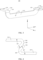
- FIG. 3 is a schematic structural diagram of a conductive bar 200 according to a second embodiment of the present disclosure.
- FIG. 4 is a schematic structural diagram of two conductive bars 200 with bending curvatures of 45° being connected.
- FIG. 5 is a schematic structural diagram of the conductive bar 200 shown in FIG. 3 from another angle of view.
- FIG. 6 is a schematic cross-sectional view of the conductive bar 200 shown in FIG. 5 along A-A.
- the conductive bar 200 may be used in the vehicle electrical device system 1 shown in FIG. 1 .
- the conductive bar 200 in this embodiment has a three-dimensional structure, and a difference from the conductive bar 200 in the first embodiment lies in that the conductive bar 200 in this embodiment further includes a first transition section 241 and a second transition section 242.
- the conductive bar 200 in this embodiment includes the first connecting section 210, the second connecting section 220, the first transition section 241, the second transition section 242, and the third connecting section 230.
- the first transition section 241 is connected between the first connecting section 210 and the second connecting section 220, to enable the first connecting section 210 and the second connecting section 220 to be located in different planes.
- the second transition section 242 is connected between the first connecting section 210 and the third connecting section 230, to enable the first connecting section 210 and the third connecting section 230 to be located in different planes.
- the first connecting section 210, the second connecting section 220, and the third connecting section 230 all have a strip shape.
- the first connecting section 210 extends in the X axis direction
- the second connecting section 220 extends in the negative Z axis direction
- the third connecting section 230 extends in the positive Z axis direction.
- the first connecting section 210 has a width ⁇ and a thickness ⁇ .
- the width ⁇ is in a range of 10 mm to 30 mm
- the thickness ⁇ is in a range of 1 mm to 10 mm.
- the first transition section 241 is an arc-shaped surface and has a bending radius R and a bending curvature ⁇ .
- a cross-sectional shape of the arc-shaped surface is a curve
- the bending radius R is a radius corresponding to the curve
- the bending curvature is a curvature corresponding to the curve.
- the bending radius R of the first transition section 241 is in a range of 2 mm to 20 mm.
- a large bending radius R is used as a transition radius, so that stress concentration can be effectively reduced, thereby effectively improving the fatigue strength of the conductive bar 200.
- the bending curvature ⁇ of the first transition section 241 is 90°, to enable an included angle between the extending direction of the second connecting section 220 and the extending direction of the first connecting section 210 to be 90°.
- the second connecting section 220 extends in the negative Z axis direction, and is parallel to the thickness direction of the first connecting section 210.
- the bending curvature ⁇ of the first transition section 241 may range from 45° to 135°, to implement that the included angle between the extending direction of the second connecting section 220 and the extending direction of the first connecting section 210 ranges from 45° to 135°.
- the second transition section 242 is an arc-shaped surface and has a bending radius R and a bending curvature ⁇ .
- the bending radius R of the second transition section 242 is in a range of 2 mm to 20 mm, so that stress concentration is reduced, thereby effectively improving the fatigue strength of the conductive bar 200.
- the bending curvature ⁇ of the second transition section 242 is 90° and is in a direction opposite to a bending direction of the first transition section 241, to make the extending directions of the second connecting section 220 and the third connecting section 230 opposite.
- the third connecting section 230 extends in the positive Z axis direction, and is parallel to the thickness direction of the first connecting section 210.
- the bending curvature ⁇ of the second transition section 242 may range from 45° to 135°, to implement that an included angle between the extending direction of the third connecting section 230 and the extending direction of the first connecting section 210 ranges from 45° to 135°.
- the bending curvatures ⁇ of the first transition section 241 and the second transition section 242 of the conductive bar 200 are 45°, and the second connecting section 220 of one conductive bar 200 and the third connecting section 230 of another conductive bar 200 can be connected by a bolt or another fastener, to implement a fixed connection between the two conductive bars 200.
- the conductive bar 200 in this embodiment may be made by bending the conductive bar 200 in the first embodiment. Specifically, the second connecting section 220 of the conductive bar 200 in the first embodiment bends in the negative Z axis direction, and the third connecting section 230 bends in the positive Z axis direction, to manufacture and form the conductive bar 200 in the second embodiment. In other embodiments, the conductive bar 200 in this embodiment may be integrally formed.
- FIG. 7 is a structural cross-sectional view of the conductive bar 200 shown in FIG. 5 at the first connecting section 210.
- the conductive bar 200 includes a conductive body 200a, a backing layer 200b, an abrasion-resistant layer 200c, and an insulating layer 200d.
- the backing layer 200b covers a surface of the conductive body 200a
- the abrasion-resistant layer 200c is arranged on a surface of the backing layer 200b away from the conductive body 200a
- the insulating layer 200d is arranged on a surface of the abrasion-resistant layer 200c away from the conductive body 200a
- the insulating layer 200d covers a part of the conductive body 200a located at the first connecting section 210.
- the insulating layer 200d may cover parts of the conductive body 200a located at the first transition section 241 and the second transition section 242.
- the insulating layer 200d does not cover parts of the conductive body 200a located at the second connecting section 220 and the third connecting section 230, to ensure that the second connecting section 220 and the third connecting section 230 can be electrically connected to the electrical device 2000.
- the three-dimensional structure shown in FIG. 3 is formed by bending the conductive body 200a, then the conductive body 200a is sequentially electroplated to form the backing layer 200b and the abrasion-resistant layer 200c, and then the insulating layer 200d covers parts of the abrasion-resistant layer 200c located at the first connecting section 210, the first transition section 241, and the second transition section 242, to manufacture and form the conductive bar 200.
- the conductive body 200a is made of a conductive material, for example, made of an aluminum alloy.
- a roughness of the surface of the conductive body 200a is controlled to be Ra ⁇ 1.6 ⁇ m, so that the fatigue strength of the conductive bar 200 can be improved, thereby avoiding the problem of damaged fatigue strength at stress concentration of the conductive bar 200 because stress concentration is generated at a sudden change of a cross-sectional size of the conductive bar 200.
- surface strengthening for example, shot blasting, is performed on the conductive body 200a, so that a compressive prestress is generated on the surface of the conductive body 200a, thereby improving the fatigue resistance of the conductive bar 200.
- shot blasting is performed on the conductive body 200a, to make the Vickers hardness of the surface of the conductive body 200a HV > 38, to resist the impact generated from fatigue.
- the conductive body 200a is sequentially plated with copper and nickel in an electroplating manner, to respectively form the backing layer 200b and the abrasion-resistant layer 200c.
- copper ions in a positive valence state are reduced to metal atoms, are attracted to the surface of the conductive body 200a, and migrate on the surface of the conductive body 200a until being incorporated into a crystal lattice to form the backing layer 200b.
- the electroplating process is performed under the "driving" with a difference between a reaction potential and an equilibrium potential, so that the backing layer 200b is compact and flat and has good bonding strength with the conductive body 200a, to ensure the adhesion of the subsequent abrasion-resistant layer 200c, thereby keeping the abrasion-resistant layer 200c from falling off.
- the abrasion-resistant layer 200c is a nickel layer, and the abrasion-resistant layer 200c has a thickness of 10 ⁇ m and a peel strength up to 35 N/mm.
- the nickel layer is arranged, so that an abrasion-resistant surface layer is obtained while an excellent electrical conductivity is ensured, thereby improving the strength of the conductive bar 200.
- the insulating layer 200d is manufactured on the abrasion-resistant layer 200c in a spray coating manner.
- the insulating layer 200d is made of an epoxy resin layer, and has a thickness ranging from 0.3 mm to 0.9 mm.
- the insulating layer 200d is arranged, so that a creepage distance and an electrical clearance of the conductive bar 200 can be increased, so as to ensure that the conductive bar 200 has a voltage resistance of 3000 V (AC), a 60-second leakage current less than 3 mA, an insulating resistance of 1000 V (DC), and a 60-second leakage insulating resistance greater than 200 m ⁇ .
- a sprayed code is manufactured on the insulating layer 200d, thereby improving the recognition and storage functions.
- the conductive bar 200 provided in the embodiments of the present disclosure has a good electrical conductivity and mechanical properties, so that the problem of stress concentration generated in long-term use under vibratory road conditions, and fractures in the conductive bar 200 due to vibration during work are avoided, thereby ensuring that the conductive bar assembly 1000 formed by using the conductive bar 200 is reliable and durable, and ensuring that a vehicle has high mileage under actual road conditions.
- the conductive bar 200 having the three-dimensional structure shown in FIG. 3 in the embodiments of the present disclosure is used as an experimental object for a simulation test to acquire a stress cloud diagram of the conductive bar 200.
- a large number of tests and experiments are carried out, and relationships between a maximum stress of the conductive bar 200 and impact factors such as an expansion coefficient, an aging temperature, an aging time, and an elastic modulus E are specifically researched.
- Some experimental results are collected as shown in Table 1 to Table 4.
- a material of the conductive bar 200 is an aluminum alloy.
- the aluminum alloy is manufactured in the following manner: taking raw material components of the aluminum alloy, and performing solution treatment and aging treatment to obtain the aluminum alloy.
- a specific testing method of the simulation test is as follows: Parameters of the conductive bar 200 and parameters of a vibration experiment are imported into a finite element analysis element to perform a simulation experiment on the conductive bar 200.
- the parameters of the vibration experiment include: a working condition of a vibration time of 22 h, a broadband frequency ranging from 10 Hz to 1000 Hz, a power density in a range of [0.2 (m/s 2 ) 2 /Hz, 30 [(m/s 2 ) 2 /Hz], a vibration condition root mean square (RMS, a vibration speed effective value) of 27.8 m/s 2 . It is required that no mechanical damage and loosening should exist after the experiment.
- Table 1 Relationship between an expansion coefficient factor and a maximum stress of a conductive bar Sample number Width ⁇ /mm Thickness ⁇ /mm Expansion coefficient ⁇ m/m ⁇ °C Maximum stress (MPa) Z210031a 16 2 17.5 92.4 Z210031b 23.6 92.4 Z210031c 28.2 92.3 Table 2 Relationship between an aging temperature factor and a maximum stress of a conductive bar Sample number Width ⁇ /mm Thickness ⁇ /mm Temperature °C of aging treatment Maximum stress (MPa) Z210032a 16 2 160 92.4 Z210032b 170 92.4 Z210032c 180 92.4 Table 3 Relationship between an aging time factor and a maximum stress of a conductive bar Sample number Width ⁇ /mm Thickness ⁇ /mm Time h of aging treatment Maximum stress (MPa) Z210033a 16 2 8 92.4 Z210033b 10 92.5 Z210033c 12 92.4 Table 4 Relationship between an elastic modulus factor and a maximum stress
- a conductive bar 200 that has a small stress and can work for a long time at a broadband frequency ranging from 10 Hz to 1000 Hz under a vibration case of a vibration speed effective value (root mean square, RMS) being greater than 27.8 m/s 2 can be designed by adjusting the elastic modulus, the width, and the thickness of the conductive bar 200.
- An aluminum alloy material is used to make the conductive bar 200 in the following experiments, and relationships between the stress of the conductive bar 200 and the width ⁇ , the thickness ⁇ , and the elastic modulus E of the conductive bar 200 are specifically researched.
- DOE design of experiments
- multiple groups of conductive bars 200 having different widths ⁇ , thicknesses ⁇ , and elastic moduli E are designed, and a simulation test is performed on the conductive bars 200 to measure stresses of conductive bars 200 in different groups.
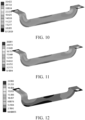
- Stress cloud diagrams of the stress cloud diagram 200 in Experimental groups 1 to 12 are shown in FIG. 8 to FIG. 19 . Parameters of the conductive bars 200 and measured maximum stresses are collected as shown in Table 5.
- the conductive bars 200 in Experimental groups 1 to 6 are respectively conductive bars manufactured and formed by using the aluminum alloys provided in Embodiments 1 to 6 in Table 7 below.
- the conductive bar 200 in Experimental group 7 is a conductive bar manufactured and formed by using the aluminum alloy provided in Embodiment 11 in Table 7 below.
- the conductive bars 200 in Experimental groups 8 and 9 are respectively conductive bars manufactured and formed by using the aluminum alloys provided in Embodiments 7 and 8 in Table 7 below.
- the conductive bars 200 in Experimental groups 10 to 12 are conductive bars manufactured and formed by using the aluminum alloy provided in Comparative example 1 in Table 7 below.
- the range of the thickness ⁇ satisfies the following feature expression (i): ⁇ 3 / E ⁇ ⁇ ⁇ 10 ⁇ 3 / E (i), and the elastic modulus E is in the range of 55 GPa to 120 GPa
- the maximum stress of the conductive bar 200 is small, a good strength effect is achieved, and long-term vibratory working conditions with a broadband frequency ranging from 10 Hz to 1000 Hz and a vibration speed effective value (root mean square, RMS) being greater than 27.8 m/s 2 can be satisfied, so that fractures in the conductive bar 200 due to vibration during work are avoided.
- the thicknesses ⁇ of the conductive bars 200 in Experimental groups 1 to 7 further satisfy the expressions: ⁇ 3 / E ⁇ ⁇ ⁇ 2 ⁇ 3 / E , ⁇ 3 / E ⁇ ⁇ ⁇ 3 ⁇ 3 / E , ⁇ 3 / E ⁇ ⁇ ⁇ 4 ⁇ 3 / E , ⁇ 3 / E ⁇ ⁇ ⁇ 5 ⁇ 3 / E , or ⁇ 3 / E ⁇ ⁇ ⁇ 6 ⁇ 3 / E .
- the thickness ⁇ satisfies the feature expression (i), but the elastic modulus E does not satisfy the range of 55 GPa to 120 GPa, the measured stress of the conductive bars 200 is small, and long-term vibratory working conditions cannot be satisfied.
- Experimental results show that only a conductive bar 200 that satisfies both the range of the thickness ⁇ being ⁇ 3 / E ⁇ ⁇ ⁇ 10 ⁇ 3 / E and the range of the elastic modulus E being 55 GPa to 120 GPa has a small stress and can satisfy long-term vibratory working conditions, thereby avoiding fractures in the conductive bar 200 due to vibration during work.
- the conductive bar 200 in Experimental group 1 is taken.
- a bolt fastener (marked as a hole 1-bolt) passes through the first connecting hole 221
- a bolt fastener (marked as a hole 2-bolt) passes through the second connecting hole 231, to fix the conductive bar 200 at a vibrating table, and then a vibration experiment is performed on the conductive bar 200.
- the conditions of the vibration experiment are: a broadband frequency ranging from 10 Hz to 1000 Hz, a power density in a range of [0.2 (m/s 2 ) 2 /Hz, 30 [(m/s 2 ) 2 /Hz], a vibration condition RMS of 27.8 m/s 2 , and a vibration time of 22 h.
- Torque values of the bolt fasteners in the conductive bar 200 before the vibration experiment and after the vibration experiment are measured, and results are collected as shown in Table 6.
- a method for measuring a torque value of a bolt fastener is measured: 1. A torque of the bolt fastener before the vibration experiment is tested by using a tightening method, a force is stably applied by using a wrest wrench, and a moment is gradually increased. When the bolt starts to generate a slight rotation, an instantaneous torque value of the bolt is maximum (because a force of static friction needs to be overcome). As the rotation continues, the torque value falls back to a temporary stable state. In this case, the torque value is a detected torque value. 2.
- a torque of the bolt fastener after the vibration experiment is tested by using a loosening method.
- a torque is slowly applied to the bolt under test by using a wrest wrench to loosen the bolt.
- An instantaneous torque value when the rotation starts is read, and is multiplied by a coefficient ranging from 1.1 to 1.2 according to experiments and experience to obtain a detected torque value.
- Table 6 Torque values of the conductive bar 200 before the vibration experiment and after the vibration experiment Sequence No.
- Test item Test method Application position Bolt size Torque value 1 Torque test (before test) Tightening method N ⁇ m Hole 1-bolt M6 6.03 Hole 2-bolt M6 6.05 2 Torque test (after test) Loosening method N ⁇ m Hole 1-bolt M6 5.43 Hole 2-bolt M6 5.39
- the experimental results show that after bearing the vibration under the road condition of a broadband frequency ranging from 10 Hz to 1000 Hz, a power density in a range of [0.2 (m/s 2 ) 2 /Hz, 30 [(m/s 2 ) 2 /Hz], and a vibration condition RMS of 27.8 m/s 2 , the conductive bar 200 provided in the embodiments of the present disclosure can still keep a fastener torque attenuation ⁇ 20%, which facilitates long-term use of the conductive bar 200 under actual vibration road conditions.
- Each of Embodiments 1 to 11 and Comparative Example 1 provides a conductive bar 200, which is specifically manufactured by using the following steps: configuring an aluminum alloy raw material according to the components shown in FIG. 7 , performing solution treatment at a temperature of 530°C for 25 min, and then performing aging treatment at a temperature of 195°C for 33 hours to obtain an aluminum alloy. Next, the aluminum alloy is cut to form a planar plate shape shown in FIG. 2 , and is then bent to obtain the conductive body 200a having the three-dimensional structure shown in FIG. 3 . Grinding, polishing, and electroplating are sequentially performed to form the backing layer 200b and the abrasion-resistant layer 200c, and spray coating is performed to form the insulating layer 200d, to obtain the conductive bar 200.
- the components of the aluminum alloy in Embodiments 1 to 11 and Comparative example 1 are all calculated in mass percentage, and the balance is Al.
- a performance test is performed on the conductive bars 200 manufactured in Embodiments 1 to 11 and Comparative example 1, and performance parameters of the conductive bars are collected as shown in Table 7.
- the International Annealed Copper Standard (IACS) is used to represent an electrical conductivity of a metal or an alloy (with reference to the standard annealed copper).
- Table 7 Components of aluminum alloys in Embodiments 1 to 11 and Comparative example 1 and performance parameters of the manufactured conductive bar 200 Si Fe Ni Zn B Ti Mg Al Yield strength MPa Tensile strength MPa Elastic modulus GPa Electrical conductivity %IACS Thermal conductivity coefficient W/m ⁇ K Embodiment 1 0.4 0.06 0.1 0.09 0.04 0.002 0.1 Balance 89 211 74.0 57.1 210 Embodiment 2 0.3 0.05 0.1 0.09 0.03 0.01 0.4 Balance 87 183 72.0 57.7 216 Embodiment 3 0.2 0.04 0.05 0.05 0.02 0.002 0.85 Balance 84 155 69.9 58.0 218 Embodiment 4 0.2 0.04 0.05 0.05 0.02 0.002 0.85 Balance 84 155 69.9 58.0 218 Embodiment 5 0.2 0.04 0.05 0.05 0.02 0.002 0.85 Balance 84 155 69.9 58.0 218 Embodiment 5 0.2 0.04 0.05 0.05 0.02
- An aluminum alloy material used for the conductive body 200a in the embodiments of the present disclosure includes the following components: 0.02% to 0.85% of Mg, 0.01% to 0.41% of Si, 0.01% to 0.04% of B, 0.01% to 0.062% of Fe, 0 to 0.096% of Zn, 0 to 0.0096% of Ti, 0 to 0.1% of Ni, 98.52% to 99.95% of Al, and impurities, where content of the impurities is ⁇ 0. 1%. It can be learned from data in Table 7 that for aluminum alloy materials made according to the foregoing component formulas in Embodiments 1 to 10, it is measured that the elastic moduli of the aluminum alloy materials are all in a range of 55 GPa to 120 GPa.
- Si and Fe are added, so that strengthening phases of Al 3 Fe and AlSiFe are formed in the aluminum alloy, thereby improving the material strength of the aluminum alloy.
- Si and Fe can improve the casting fluidity and the mold stickiness.
- Zn and Ni can improve the strength without reducing the electrical conductivity in the aluminum alloy.
- the aluminum alloy material can have both mechanical properties and electrical conductivity by controlling the content of Si to be less than 0.5 wt.%, the content of Fe to be less than 0.1 wt.%, the content of Ni to be less than 0.1 wt.%, and the content of Zn to be less than 0.1 wt.%.
- the aluminum alloy material has high strength by controlling the content of impurity elements. After the aluminum alloy materials in Embodiments 1 to 10 of the present disclosure are bent by 90° (1 t), the surfaces of the aluminum alloy materials have no cracks.
- the aluminum alloy materials in Embodiments 1 to 10 have a yield strength ⁇ 75 MPa, a tensile strength ⁇ 114 MPa, an electrical conductivity ⁇ 57%IACS, and a thermal conductivity coefficient satisfying 200 W/m ⁇ K to 230 W/m ⁇ K, and have good mechanical properties and electrical conductivity, thereby resolving the problem that existing aluminum alloy materials have lower mechanical properties while having a better electrical conductivity.
- the aluminum alloy material has a smaller density than a copper material, and has advantages of a small density and a light weight.
- a conductive bar 200 manufactured by using the aluminum alloy material provided in the embodiments of the present disclosure satisfies lightweight development requirements of modern vehicles.
- the elastic modulus of the conductive bar 200 manufactured by using the aluminum alloy material provided in Embodiment 11 satisfies 55 GPa to 120 GPa.
- the thickness ⁇ is adjusted to satisfy the feature expression (i), a conductive bar 200 with a small stress can be obtained.
- the content of Mg in the aluminum alloy material formula provided in Embodiment 11 is up to 9.2%, and the electrical conductivity and the thermal conductivity coefficient of the obtained conductive bar 200 are both reduced.
- the conductive bars 200 in Embodiments 1 to 10 have both good mechanical properties and a better electrical conductivity, and have a better application prospect in vehicle electrical device systems.
- the alloy material provided in Comparative example 1 has a small elastic modulus and a small thermal conductivity coefficient, which is not conducive to improving the mechanical properties and the heat dissipation effect of the conductive bar 200.
- the aluminum alloy materials in Embodiments 1 to 10 have thermal conductivity coefficients ranging from 200 W/m ⁇ K to 230 W/m ⁇ K, have a better electrical conductivity, and are further conducive to improving the heat dissipation effect of the conductive bar 200.
Landscapes
- Non-Insulated Conductors (AREA)
- Conductive Materials (AREA)
- Elimination Of Static Electricity (AREA)
Abstract
Description
- The present disclosure claims priority to and benefits of
Chinese Patent Application No. 202210760496.7, filed on June 30, 2022 - The present disclosure relates to the field of conductive bar technologies, and in particular, to a conductive bar, a conductive bar assembly, and a vehicle electrical device system.
- Electrical devices on a vehicle are usually connected by a conductive bar. During travelling of the vehicle under long-term vibratory road conditions, stress concentration may occur in the conductive bar during long-term use, causing fractures in the conductive bar due to vibration during work. As a result, the conductive bar assembly of the vehicle is not durable, and the vehicle cannot achieve high mileage under actual road conditions.
- An objective of the present disclosure is to provide a conductive bar, a conductive bar assembly, and a vehicle electrical device system. The conductive bar can be used under long-term vibratory road conditions, to avoid fractures in the conductive bar due to vibration during work, and resolve the problem of stress concentration in the conductive bar during long-term use, thereby ensuring that a conductive bar assembly manufactured and formed by using the conductive bar is reliable and durable and the vehicle can achieve high mileage under actual road conditions.
- The present disclosure provides a conductive bar, configured to be electrically connected between two electrical devices. The conductive bar includes at least one connecting section. An elastic modulus of the connecting section is E. A width of the connecting section is ω. A thickness of the connecting section is δ. The thickness δ of the connecting section satisfies

- Optionally, the thickness δ of the connecting section satisfies


- Optionally, multiple connecting sections are provided, the multiple connecting sections include a first connecting section, a second connecting section, and a third connecting section, and the second connecting section and the third connecting section are respectively arranged at two opposite ends of the first connecting section and are respectively configured to be electrically connected to the two electrical devices.
- Optionally, an extending direction of the first connecting section is parallel to a first direction, extending directions of the second connecting section and the third connecting section are both parallel to a second direction, and the first direction is perpendicular to the second direction.
- Optionally, the conductive bar has a planar plate shape, the second direction being perpendicular to a thickness direction of the first connecting section.
- Optionally, the conductive bar has a three-dimensional structure, the second direction being parallel to a thickness direction of the first connecting section.
- Optionally, the multiple connecting sections further include a first transition section and a second transition section, the first transition section is connected between the first connecting section and the second connecting section, and the second transition section is connected between the first connecting section and the third connecting section.
- Optionally, an included angle between an extending direction of the second connecting section and an extending direction of the first connecting section ranges from 45° to 135°, and an included angle between an extending direction of the third connecting section and the extending direction of the first connecting section ranges from 45° to 135°.
- Optionally, a bending direction of the first transition section is opposite to a bending direction of the second transition section.
- Optionally, a fixing hole is provided in the first connecting section, the fixing hole penetrates the first connecting section along the thickness direction of the first connecting section, a first connecting hole is provided in the second connecting section, the first connecting hole penetrates the second connecting section along a thickness direction of the second connecting section, a second connecting hole is provided in the third connecting section, and the second connecting hole penetrates the third connecting section along a thickness direction of the third connecting section.
- Optionally, the conductive bar includes a conductive body and an abrasion-resistant layer covering a surface of the conductive body, and a roughness of the surface of the conductive body being Ra ≤ 1.6 µm.
- Optionally, a material of the conductive body is an aluminum alloy, and the aluminum alloy includes components of the following mass percentage: 0.02% to 0.85% of Mg, 0.01% to 0.41% of Si, 0.01% to 0.04% of B, 0.01% to 0.062% of Fe, 0 to 0.096% of Zn, 0 to 0.0096% of Ti, 0 to 0.1% of Ni, 98.52% to 99.95% of Al, and impurities, where content of the impurities is ≤ 0.1%.
- Optionally, a Vickers hardness of the surface of the conductive body is HV > 38.
- Optionally, the conductive bar further includes a backing layer, the backing layer covering the surface of the conductive body, and the abrasion-resistant layer being arranged on a surface of the backing layer away from the conductive body.
- Optionally, the conductive bar further includes an insulating layer, and the insulating layer being arranged on a surface of the abrasion-resistant layer away from the conductive body.
- Optionally, the conductive bar has a yield strength ≥ 75 MPa, a tensile strength ≥ 114 MPa, and an electrical conductivity ≥ 57%IACS.
- Optionally, the conductive bar has a thermal conductivity coefficient ranging from 200 W/m·K to 230 W/m·K.
- The present disclosure further provides a conductive bar assembly, including a connecting substrate and multiple foregoing conductive bars. The multiple conductive bars are all mounted on the connecting substrate and are spaced away from each other.
- The multiple conductive bars form multiple conductive bar groups. Each conductive bar group includes multiple conductive bars. The multiple conductive bars of each conductive bar group are parallel to each other.
- The present disclosure further provides a vehicle electrical device system, including two electrical devices and the foregoing conductive bar. The conductive bar is electrically connected between the two electrical devices.
- In the present disclosure, it is found out through a large amount of experimental research that a conductive bar satisfying the expression

- To describe the technical solutions in the embodiments of the present disclosure or in the related art more clearly, the following briefly introduces the accompanying drawings required for describing the embodiments or the related art. Apparently, the accompanying drawings in the following description show merely some embodiments of the present disclosure, and a person of ordinary skill in the art may still derive other drawings from these accompanying drawings without creative efforts.
-
FIG. 1 is a schematic structural arrangement diagram of a vehicle electrical device system according to an embodiment of the present disclosure; -
FIG. 2 is a schematic structural diagram of a conductive bar according to a first embodiment of the present disclosure; -
FIG. 3 is a schematic structural diagram of a conductive bar according to a second embodiment of the present disclosure; -
FIG. 4 is a schematic structural diagram of two conductive bars with bending curvatures of 45° being connected; -
FIG. 5 is a schematic structural diagram of the conductive bar shown inFIG. 3 from another angle of view; -
FIG. 6 is a schematic cross-sectional view of the conductive bar shown inFIG. 5 along A-A; -
FIG. 7 is a structural cross-sectional view of the conductive bar shown inFIG. 5 at a first connecting section; -
FIG. 8 is a stress cloud diagram of a conductive bar inExperimental group 1; -
FIG. 9 is a stress cloud diagram of a conductive bar in Experimental group 2; -
FIG. 10 is a stress cloud diagram of a conductive bar inExperimental group 3; -
FIG. 11 is a stress cloud diagram of a conductive bar in Experimental group 4; -
FIG. 12 is a stress cloud diagram of a conductive bar in Experimental group 5; -
FIG. 13 is a stress cloud diagram of a conductive bar in Experimental group 6; -
FIG. 14 is a stress cloud diagram of a conductive bar inExperimental group 7; -
FIG. 15 is a stress cloud diagram of a conductive bar in Experimental group 8; -
FIG. 16 is a stress cloud diagram of a conductive bar in Experimental group 9; -
FIG. 17 is a stress cloud diagram of a conductive bar in Experimental group 10; -
FIG. 18 is a stress cloud diagram of a conductive bar in Experimental group 11; and -
FIG. 19 is a stress cloud diagram of a conductive bar in Experimental group 12. - The following clearly and completely describes the technical solutions in the embodiments of the present disclosure with reference to the accompanying drawings in the embodiments of the present disclosure. Apparently, the described embodiments are only some of the embodiments of the present disclosure rather than all of the embodiments. All other embodiments obtained by a person of ordinary skill in the art based on the embodiments of the present disclosure without creative efforts shall fall within the protection scope of the present disclosure.
-
FIG. 1 is a schematic structural arrangement diagram of a vehicleelectrical device system 1 according to an embodiment of the present disclosure. - The vehicle
electrical device system 1 can be used in a vehicle, and includes a conductive bar assembly 1000 and multipleelectrical devices 2000. The multipleelectrical devices 2000 may be electrically connected by the conductive bar assembly 1000. For example, theelectrical device 2000 may be a battery, a transformer, a motor, a circuit breaker, an alternating-current/direct-current system, a breaker cabinet, a capacitor, or another device. - Specifically, the conductive bar assembly 1000 includes a connecting
substrate 100 and multipleconductive bars 200. The connectingsubstrate 100 is an insulating substrate. The multipleconductive bars 200 are all mounted on the connectingsubstrate 100 and are spaced away from each other. In this embodiment, the connectingsubstrate 100 is an integral structure.FIG. 1 only shows a partial structure of the connectingsubstrate 100. It can be understood that, in other embodiments, the connectingsubstrate 100 may be multiple separate structures. The multipleconductive bars 200 form multiple conductive bar groups, and as shown in the figure, form three vertical rows. Each conductive bar group includes multipleconductive bars 200. The multipleconductive bars 200 of each conductive bar group are parallel to each other.Conductive bars 200 in different conductive bar groups are electrically connected, to implement electrical connections between the different conductive bar groups. - The multiple
electrical devices 2000 may be electrically connected by the multipleconductive bars 200, to implement electrical connections between the multipleelectrical devices 2000. As shown in the figure, theelectrical devices 2000 in each horizontal row are electrically connected by theconductive bars 200, to implement electrical connections between theelectrical devices 2000. The multipleelectrical devices 2000 may be electrically connected by the conductive bar assembly 1000, and through the electrical connections to different conductive bar groups, the three-dimensional layout of theelectrical devices 2000 in space is implemented. -
FIG. 2 is a schematic structural diagram of aconductive bar 200 according to a first embodiment of the present disclosure. For example, theconductive bar 200 may be used in the vehicleelectrical device system 1 shown inFIG. 1 . - For ease of description, it is defined that a length direction of the
conductive bar 200 shown inFIG. 2 is an X axis direction, a width direction is a Y axis direction, and a thickness direction is a Z axis direction. The X axis direction, the Z axis direction, and the Y axis direction are perpendicular to each other. - The
conductive bar 200 includes at least one connecting section. In this embodiment, theconductive bar 200 has a planar plate shape. Three connecting sections are provided, and include a first connectingsection 210, a second connectingsection 220, and a third connectingsection 230. An extending direction of the first connectingsection 210 is parallel to a first direction. Extending directions of the second connectingsection 220 and the third connectingsection 230 are parallel to a second direction, and are arranged spaced away at two opposite ends of the first connectingsection 210. In this embodiment, the first direction is the X axis direction, the second direction is the Y axis direction, and the second direction is perpendicular to the thickness direction of the first connectingsection 210. - The first connecting
section 210 has a width ω and a thickness δ. In some specific embodiments, the width ω is in a range of 10 mm to 30 mm, and the thickness δ is in a range of 1 mm to 10 mm. A fixinghole 211 is provided in the first connectingsection 210. The fixinghole 211 penetrates the first connectingsection 210 along the thickness direction of the first connectingsection 210. A bolt or another fastener may pass through the fixinghole 211 and a through hole in the connectingsubstrate 100 to fix the first connectingsection 210 at the connectingsubstrate 100, to implement a fixed connection between theconductive bar 200 and the connectingsubstrate 100. - The second connecting
section 220 has a width ω and a thickness δ. In some specific embodiments, the width ω is in a range of 10 mm to 30 mm, and the thickness δ is in a range of 1 mm to 10 mm. A first connectinghole 221 is provided in the second connectingsection 220. The first connectinghole 221 penetrates the second connectingsection 220 along a thickness direction of the second connectingsection 220. - The third connecting
section 230 has a width ω and a thickness δ. In some specific embodiments, the width ω is in a range of 10 mm to 30 mm, and the thickness δ is in a range of 1 mm to 10 mm. A second connectinghole 231 is provided in the third connectingsection 230. The second connectinghole 231 penetrates the third connectingsection 230 along a thickness direction of the third connectingsection 230. A bolt or another fastener may pass through the first connectinghole 221 to electrically connect the second connectingsection 220 to oneelectrical device 2000, and pass through the second connectinghole 231 to electrically connect the third connectingsection 230 to anotherelectrical device 2000, so as to implement electrical connections between oneconductive bar 200 and the twoelectrical devices 2000. The first connectinghole 221 and the second connectinghole 231 are disposed, so that it can be implemented that theconductive bar 200 is fixedly connected to theelectrical device 2000 by a bolt or another fastener, which facilitates after sales service and repair, and also resolves the problem of inconvenience in assembly and disassembly because welding needs to be used for connection in an existingconductive bar 200. - It can be understood that, a bolt or another fastener may pass through the first connecting
hole 221 of oneconductive bar 200 and the second connectinghole 231 of anotherconductive bar 200, to fixedly connect the twoconductive bars 200, so as to implement electrical connections between twoelectrical devices 2000 by the twoconductive bars 200. -
FIG. 3 is a schematic structural diagram of aconductive bar 200 according to a second embodiment of the present disclosure.FIG. 4 is a schematic structural diagram of twoconductive bars 200 with bending curvatures of 45° being connected.FIG. 5 is a schematic structural diagram of theconductive bar 200 shown inFIG. 3 from another angle of view.FIG. 6 is a schematic cross-sectional view of theconductive bar 200 shown inFIG. 5 along A-A. For example, theconductive bar 200 may be used in the vehicleelectrical device system 1 shown inFIG. 1 . - As shown in
FIG. 3 , theconductive bar 200 in this embodiment has a three-dimensional structure, and a difference from theconductive bar 200 in the first embodiment lies in that theconductive bar 200 in this embodiment further includes afirst transition section 241 and asecond transition section 242. Specifically, in this embodiment, theconductive bar 200 in this embodiment includes the first connectingsection 210, the second connectingsection 220, thefirst transition section 241, thesecond transition section 242, and the third connectingsection 230. Thefirst transition section 241 is connected between the first connectingsection 210 and the second connectingsection 220, to enable the first connectingsection 210 and the second connectingsection 220 to be located in different planes. Thesecond transition section 242 is connected between the first connectingsection 210 and the third connectingsection 230, to enable the first connectingsection 210 and the third connectingsection 230 to be located in different planes. - In this embodiment, the first connecting
section 210, the second connectingsection 220, and the third connectingsection 230 all have a strip shape. The first connectingsection 210 extends in the X axis direction, the second connectingsection 220 extends in the negative Z axis direction, and the third connectingsection 230 extends in the positive Z axis direction. The first connectingsection 210 has a width ω and a thickness δ. In some specific embodiments, the width ω is in a range of 10 mm to 30 mm, and the thickness δ is in a range of 1 mm to 10 mm. In this embodiment, thefirst transition section 241 is an arc-shaped surface and has a bending radius R and a bending curvature θ. A cross-sectional shape of the arc-shaped surface is a curve, the bending radius R is a radius corresponding to the curve, and the bending curvature is a curvature corresponding to the curve. In some specific embodiments, the bending radius R of thefirst transition section 241 is in a range of 2 mm to 20 mm. A large bending radius R is used as a transition radius, so that stress concentration can be effectively reduced, thereby effectively improving the fatigue strength of theconductive bar 200. The bending curvature θ of thefirst transition section 241 is 90°, to enable an included angle between the extending direction of the second connectingsection 220 and the extending direction of the first connectingsection 210 to be 90°. To be specific, the second connectingsection 220 extends in the negative Z axis direction, and is parallel to the thickness direction of the first connectingsection 210. In other embodiments, the bending curvature θ of thefirst transition section 241 may range from 45° to 135°, to implement that the included angle between the extending direction of the second connectingsection 220 and the extending direction of the first connectingsection 210 ranges from 45° to 135°. - In this embodiment, the
second transition section 242 is an arc-shaped surface and has a bending radius R and a bending curvature θ. In some specific embodiments, the bending radius R of thesecond transition section 242 is in a range of 2 mm to 20 mm, so that stress concentration is reduced, thereby effectively improving the fatigue strength of theconductive bar 200. The bending curvature θ of thesecond transition section 242 is 90° and is in a direction opposite to a bending direction of thefirst transition section 241, to make the extending directions of the second connectingsection 220 and the third connectingsection 230 opposite. To be specific, the third connectingsection 230 extends in the positive Z axis direction, and is parallel to the thickness direction of the first connectingsection 210. In other embodiments, the bending curvature θ of thesecond transition section 242 may range from 45° to 135°, to implement that an included angle between the extending direction of the third connectingsection 230 and the extending direction of the first connectingsection 210 ranges from 45° to 135°. In some specific embodiments, as shown inFIG. 4 , the bending curvatures θ of thefirst transition section 241 and thesecond transition section 242 of theconductive bar 200 are 45°, and the second connectingsection 220 of oneconductive bar 200 and the third connectingsection 230 of anotherconductive bar 200 can be connected by a bolt or another fastener, to implement a fixed connection between the twoconductive bars 200. - The
conductive bar 200 in this embodiment may be made by bending theconductive bar 200 in the first embodiment. Specifically, the second connectingsection 220 of theconductive bar 200 in the first embodiment bends in the negative Z axis direction, and the third connectingsection 230 bends in the positive Z axis direction, to manufacture and form theconductive bar 200 in the second embodiment. In other embodiments, theconductive bar 200 in this embodiment may be integrally formed. -
FIG. 7 is a structural cross-sectional view of theconductive bar 200 shown inFIG. 5 at the first connectingsection 210. - The
conductive bar 200 includes aconductive body 200a, abacking layer 200b, an abrasion-resistant layer 200c, and an insulatinglayer 200d. Thebacking layer 200b covers a surface of theconductive body 200a, the abrasion-resistant layer 200c is arranged on a surface of thebacking layer 200b away from theconductive body 200a, the insulatinglayer 200d is arranged on a surface of the abrasion-resistant layer 200c away from theconductive body 200a, and the insulatinglayer 200d covers a part of theconductive body 200a located at the first connectingsection 210. It can be understood that, in theconductive bar 200 in this embodiment, the insulatinglayer 200d may cover parts of theconductive body 200a located at thefirst transition section 241 and thesecond transition section 242. The insulatinglayer 200d does not cover parts of theconductive body 200a located at the second connectingsection 220 and the third connectingsection 230, to ensure that the second connectingsection 220 and the third connectingsection 230 can be electrically connected to theelectrical device 2000. - In the
conductive bar 200 in this embodiment, the three-dimensional structure shown inFIG. 3 is formed by bending theconductive body 200a, then theconductive body 200a is sequentially electroplated to form thebacking layer 200b and the abrasion-resistant layer 200c, and then the insulatinglayer 200d covers parts of the abrasion-resistant layer 200c located at the first connectingsection 210, thefirst transition section 241, and thesecond transition section 242, to manufacture and form theconductive bar 200. - Specifically, the
conductive body 200a is made of a conductive material, for example, made of an aluminum alloy. In some specific embodiments, a roughness of the surface of theconductive body 200a is controlled to be Ra ≤ 1.6 µm, so that the fatigue strength of theconductive bar 200 can be improved, thereby avoiding the problem of damaged fatigue strength at stress concentration of theconductive bar 200 because stress concentration is generated at a sudden change of a cross-sectional size of theconductive bar 200. In addition, surface strengthening, for example, shot blasting, is performed on theconductive body 200a, so that a compressive prestress is generated on the surface of theconductive body 200a, thereby improving the fatigue resistance of theconductive bar 200. In some specific embodiments, shot blasting is performed on theconductive body 200a, to make the Vickers hardness of the surface of theconductive body 200a HV > 38, to resist the impact generated from fatigue. - In this embodiment, the
conductive body 200a is sequentially plated with copper and nickel in an electroplating manner, to respectively form thebacking layer 200b and the abrasion-resistant layer 200c. In an electroplating process, copper ions in a positive valence state are reduced to metal atoms, are attracted to the surface of theconductive body 200a, and migrate on the surface of theconductive body 200a until being incorporated into a crystal lattice to form thebacking layer 200b. The electroplating process is performed under the "driving" with a difference between a reaction potential and an equilibrium potential, so that thebacking layer 200b is compact and flat and has good bonding strength with theconductive body 200a, to ensure the adhesion of the subsequent abrasion-resistant layer 200c, thereby keeping the abrasion-resistant layer 200c from falling off. In this embodiment, the abrasion-resistant layer 200c is a nickel layer, and the abrasion-resistant layer 200c has a thickness of 10 µm and a peel strength up to 35 N/mm. The nickel layer is arranged, so that an abrasion-resistant surface layer is obtained while an excellent electrical conductivity is ensured, thereby improving the strength of theconductive bar 200. - In this embodiment, the insulating
layer 200d is manufactured on the abrasion-resistant layer 200c in a spray coating manner. The insulatinglayer 200d is made of an epoxy resin layer, and has a thickness ranging from 0.3 mm to 0.9 mm. The insulatinglayer 200d is arranged, so that a creepage distance and an electrical clearance of theconductive bar 200 can be increased, so as to ensure that theconductive bar 200 has a voltage resistance of 3000 V (AC), a 60-second leakage current less than 3 mA, an insulating resistance of 1000 V (DC), and a 60-second leakage insulating resistance greater than 200 mΩ. In some embodiments, a sprayed code is manufactured on the insulatinglayer 200d, thereby improving the recognition and storage functions. - The
conductive bar 200 provided in the embodiments of the present disclosure has a good electrical conductivity and mechanical properties, so that the problem of stress concentration generated in long-term use under vibratory road conditions, and fractures in theconductive bar 200 due to vibration during work are avoided, thereby ensuring that the conductive bar assembly 1000 formed by using theconductive bar 200 is reliable and durable, and ensuring that a vehicle has high mileage under actual road conditions. - Numerous factors are related to the stress performance of the
conductive bar 200. Theconductive bar 200 having the three-dimensional structure shown inFIG. 3 in the embodiments of the present disclosure is used as an experimental object for a simulation test to acquire a stress cloud diagram of theconductive bar 200. In addition, a large number of tests and experiments are carried out, and relationships between a maximum stress of theconductive bar 200 and impact factors such as an expansion coefficient, an aging temperature, an aging time, and an elastic modulus E are specifically researched. Some experimental results are collected as shown in Table 1 to Table 4. A material of theconductive bar 200 is an aluminum alloy. The aluminum alloy is manufactured in the following manner: taking raw material components of the aluminum alloy, and performing solution treatment and aging treatment to obtain the aluminum alloy. A specific testing method of the simulation test is as follows: Parameters of theconductive bar 200 and parameters of a vibration experiment are imported into a finite element analysis element to perform a simulation experiment on theconductive bar 200. The parameters of the vibration experiment include: a working condition of a vibration time of 22 h, a broadband frequency ranging from 10 Hz to 1000 Hz, a power density in a range of [0.2 (m/s2)2/Hz, 30 [(m/s2)2/Hz], a vibration condition root mean square (RMS, a vibration speed effective value) of 27.8 m/s2. It is required that no mechanical damage and loosening should exist after the experiment.Table 1 Relationship between an expansion coefficient factor and a maximum stress of a conductive bar Sample number Width ω/mm Thickness δ/mm Expansion coefficient µm/m·°C Maximum stress (MPa) Z210031a 16 2 17.5 92.4 Z210031b 23.6 92.4 Z210031c 28.2 92.3 Table 2 Relationship between an aging temperature factor and a maximum stress of a conductive bar Sample number Width ω/mm Thickness δ/mm Temperature °C of aging treatment Maximum stress (MPa) Z210032a 16 2 160 92.4 Z210032b 170 92.4 Z210032c 180 92.4 Table 3 Relationship between an aging time factor and a maximum stress of a conductive bar Sample number Width ω/mm Thickness δ/mm Time h of aging treatment Maximum stress (MPa) Z210033a 16 2 8 92.4 Z210033b 10 92.5 Z210033c 12 92.4 Table 4 Relationship between an elastic modulus factor and a maximum stress of a conductive bar Sample number Width ω/mm Thickness δ/mm Elastic modulus E GPa Maximum stress (MPa) Z210034a 16 2 35 114.4 Z210034b 74 90.9 Z210034c 69.9 92.4 - It can be seen from Table 1 to Table 4, none of the expansion coefficient factor, the aging temperature factor, and the aging time factor significantly affects the stress of the
conductive bar 200, and the elastic modulus factor significantly affects the stress of theconductive bar 200. In the present disclosure, the research of a large number of experiments is carried out, and an elastic modulus is selected from numerous impact factors as a key factor that affects the stress of theconductive bar 200. Aconductive bar 200 that has a small stress and can work for a long time at a broadband frequency ranging from 10 Hz to 1000 Hz under a vibration case of a vibration speed effective value (root mean square, RMS) being greater than 27.8 m/s2 can be designed by adjusting the elastic modulus, the width, and the thickness of theconductive bar 200. - An aluminum alloy material is used to make the
conductive bar 200 in the following experiments, and relationships between the stress of theconductive bar 200 and the width ω, the thickness δ, and the elastic modulus E of theconductive bar 200 are specifically researched. Specifically, a method of design of experiments (DOE) single-factor adjustment is used in the embodiments of the present disclosure, multiple groups ofconductive bars 200 having different widths ω, thicknesses δ, and elastic moduli E are designed, and a simulation test is performed on theconductive bars 200 to measure stresses ofconductive bars 200 in different groups. Stress cloud diagrams of the stress cloud diagram 200 inExperimental groups 1 to 12 are shown inFIG. 8 to FIG. 19 . Parameters of theconductive bars 200 and measured maximum stresses are collected as shown in Table 5. Theconductive bars 200 inExperimental groups 1 to 6 are respectively conductive bars manufactured and formed by using the aluminum alloys provided inEmbodiments 1 to 6 in Table 7 below. Theconductive bar 200 inExperimental group 7 is a conductive bar manufactured and formed by using the aluminum alloy provided in Embodiment 11 in Table 7 below. Theconductive bars 200 in Experimental groups 8 and 9 are respectively conductive bars manufactured and formed by using the aluminum alloys provided inEmbodiments 7 and 8 in Table 7 below. Theconductive bars 200 in Experimental groups 10 to 12 are conductive bars manufactured and formed by using the aluminum alloy provided in Comparative example 1 in Table 7 below.Table 5 Parameters of the conductive bars 200 in different groups and measured maximum stressesExperimental group Width ω/mm Thickness δ/mm Elastic modulus E/GPa Maximum stress (MPa) 1 16 4 74.0 43.279 2 16 5 72.0 35.752 3 16 8 69.9 33.422 4 16 11 69.9 28.081 5 16 20 69.9 23.903 6 20 5 72.0 46.230 7 16 4 58 64.100 8 16 2 74 90.900 9 20 3 69.9 86.895 10 16 2 35 110.030 11 10 60 35 114.370 12 11 2 35 110.740 - In the embodiments of the present disclosure, when it is optimized by fitting a large amount of experimental data that the range of the thickness δ satisfies the following feature expression (i):

conductive bar 200 is small, a good strength effect is achieved, and long-term vibratory working conditions with a broadband frequency ranging from 10 Hz to 1000 Hz and a vibration speed effective value (root mean square, RMS) being greater than 27.8 m/s2 can be satisfied, so that fractures in theconductive bar 200 due to vibration during work are avoided. - It can be seen from data in some experimental groups shown in Table 5 that for the
conductive bars 200 inExperimental groups 1 to 7, when the thicknesses δ satisfy the foregoing feature expression (i) and the elastic moduli E satisfy the range of 55 GPa to 120 GPa, the measured stresses of theconductive bars 200 are small, and long-term vibratory working conditions can be satisfied. In addition, the thicknesses δ of theconductive bars 200 inExperimental groups 1 to 7 further satisfy the expressions:


- As can be learned by comparing Experimental groups 8 to 12 and
Experimental groups 1 to 7, for theconductive bars 200 in Experimental groups 8 and 9, although the elastic moduli E satisfy the range of 55 GPa to 120 GPa, but the thicknesses δ do not satisfy the feature expression (i). The measured stresses of theconductive bars 200 are very large, and cannot satisfy long-term vibratory working conditions. For theconductive bars 200 in Experimental groups 10 and 11, the elastic moduli E are all less than 55 GPa, and the thicknesses δ do not satisfy the feature expression (i). The maximum stress of theconductive bar 200 cannot be effectively reduced by adjusting the width ω or the thickness δ, and long-term vibratory working conditions cannot be satisfied. For theconductive bar 200 in Experimental group 12, the thickness δ satisfies the feature expression (i), but the elastic modulus E does not satisfy the range of 55 GPa to 120 GPa, the measured stress of theconductive bars 200 is small, and long-term vibratory working conditions cannot be satisfied. Experimental results show that only aconductive bar 200 that satisfies both the range of the thickness δ being
conductive bar 200 due to vibration during work. - The
conductive bar 200 inExperimental group 1 is taken. A bolt fastener (marked as a hole 1-bolt) passes through the first connectinghole 221, a bolt fastener (marked as a hole 2-bolt) passes through the second connectinghole 231, to fix theconductive bar 200 at a vibrating table, and then a vibration experiment is performed on theconductive bar 200. The conditions of the vibration experiment are: a broadband frequency ranging from 10 Hz to 1000 Hz, a power density in a range of [0.2 (m/s2)2/Hz, 30 [(m/s2)2/Hz], a vibration condition RMS of 27.8 m/s2, and a vibration time of 22 h. Torque values of the bolt fasteners in theconductive bar 200 before the vibration experiment and after the vibration experiment are measured, and results are collected as shown in Table 6. A method for measuring a torque value of a bolt fastener is measured: 1. A torque of the bolt fastener before the vibration experiment is tested by using a tightening method, a force is stably applied by using a wrest wrench, and a moment is gradually increased. When the bolt starts to generate a slight rotation, an instantaneous torque value of the bolt is maximum (because a force of static friction needs to be overcome). As the rotation continues, the torque value falls back to a temporary stable state. In this case, the torque value is a detected torque value. 2. A torque of the bolt fastener after the vibration experiment is tested by using a loosening method. A torque is slowly applied to the bolt under test by using a wrest wrench to loosen the bolt. An instantaneous torque value when the rotation starts is read, and is multiplied by a coefficient ranging from 1.1 to 1.2 according to experiments and experience to obtain a detected torque value.Table 6 Torque values of the conductive bar 200 before the vibration experiment and after the vibration experimentSequence No. Test item Test method Application position Bolt size Torque value 1 Torque test (before test) Tightening method N·m Hole 1-bolt M6 6.03 Hole 2-bolt M6 6.05 2 Torque test (after test) Loosening method N·m Hole 1-bolt M6 5.43 Hole 2-bolt M6 5.39 - A torque attenuation value of the hole 1-bolt fastener is = (6.03 - 5.43)/6.03 × 100% = 9.95% < 20%, and a torque attenuation value of the hole 2-bolt fastener is = (6.05 - 5.39)/6.05 × 100% = 10.91% < 20%. The experimental results show that after bearing the vibration under the road condition of a broadband frequency ranging from 10 Hz to 1000 Hz, a power density in a range of [0.2 (m/s2)2/Hz, 30 [(m/s2)2/Hz], and a vibration condition RMS of 27.8 m/s2, the
conductive bar 200 provided in the embodiments of the present disclosure can still keep a fastener torque attenuation < 20%, which facilitates long-term use of theconductive bar 200 under actual vibration road conditions. - Each of
Embodiments 1 to 11 and Comparative Example 1 provides aconductive bar 200, which is specifically manufactured by using the following steps: configuring an aluminum alloy raw material according to the components shown inFIG. 7 , performing solution treatment at a temperature of 530°C for 25 min, and then performing aging treatment at a temperature of 195°C for 33 hours to obtain an aluminum alloy. Next, the aluminum alloy is cut to form a planar plate shape shown inFIG. 2 , and is then bent to obtain theconductive body 200a having the three-dimensional structure shown inFIG. 3 . Grinding, polishing, and electroplating are sequentially performed to form thebacking layer 200b and the abrasion-resistant layer 200c, and spray coating is performed to form the insulatinglayer 200d, to obtain theconductive bar 200. The components of the aluminum alloy inEmbodiments 1 to 11 and Comparative example 1 are all calculated in mass percentage, and the balance is Al. - A performance test is performed on the
conductive bars 200 manufactured inEmbodiments 1 to 11 and Comparative example 1, and performance parameters of the conductive bars are collected as shown in Table 7. The International Annealed Copper Standard (IACS) is used to represent an electrical conductivity of a metal or an alloy (with reference to the standard annealed copper).Table 7 Components of aluminum alloys in Embodiments 1 to 11 and Comparative example 1 and performance parameters of the manufacturedconductive bar 200Si Fe Ni Zn B Ti Mg Al Yield strength MPa Tensile strength MPa Elastic modulus GPa Electrical conductivity %IACS Thermal conductivity coefficient W/m· K Embodiment 1 0.4 0.06 0.1 0.09 0.04 0.002 0.1 Balance 89 211 74.0 57.1 210 Embodiment 2 0.3 0.05 0.1 0.09 0.03 0.01 0.4 Balance 87 183 72.0 57.7 216 Embodiment 30.2 0.04 0.05 0.05 0.02 0.002 0.85 Balance 84 155 69.9 58.0 218 Embodiment 4 0.2 0.04 0.05 0.05 0.02 0.002 0.85 Balance 84 155 69.9 58.0 218 Embodiment 5 0.2 0.04 0.05 0.05 0.02 0.002 0.85 Balance 84 155 69.9 58.0 218 Embodiment 6 0.3 0.05 0.1 0.09 0.03 0.01 0.4 Balance 87 183 72.0 57.7 216 Embodiment 70.4 0.06 0.1 0.09 0.04 0.002 0.1 Balance 89 211 74.0 57.1 210 Embodiment 8 0.2 0.04 0.05 0.05 0.02 0.002 0.85 Balance 84 155 69.9 58.0 218 Embodiment 9 0.2 0.04 0 0 0.01 0 0.02 Balance 82 132 68.8 58.6 220 Embodiment 10 0.01 0.01 0.1 0.09 0.01 0 0.02 Balance 81 119 68.2 59.8 226 Embodiment 11 0.2 0.04 0.1 0.09 0.04 0.002 9.2 Balance 75 109 58 51 160 Si Fe Ni Cu Mn Ti Mg Al Impurity Elastic modulus GPa Thermal conductivity coefficient W/m·K Comparative example 1 0.03 0.05 0.004 0.004 0.06 0.002 99.6 0.05 0.2 35 110 - An aluminum alloy material used for the
conductive body 200a in the embodiments of the present disclosure includes the following components: 0.02% to 0.85% of Mg, 0.01% to 0.41% of Si, 0.01% to 0.04% of B, 0.01% to 0.062% of Fe, 0 to 0.096% of Zn, 0 to 0.0096% of Ti, 0 to 0.1% of Ni, 98.52% to 99.95% of Al, and impurities, where content of the impurities is ≤ 0. 1%. It can be learned from data in Table 7 that for aluminum alloy materials made according to the foregoing component formulas inEmbodiments 1 to 10, it is measured that the elastic moduli of the aluminum alloy materials are all in a range of 55 GPa to 120 GPa. - In the aluminum alloy material, Si and Fe are added, so that strengthening phases of Al3Fe and AlSiFe are formed in the aluminum alloy, thereby improving the material strength of the aluminum alloy. Si and Fe can improve the casting fluidity and the mold stickiness. However, if excessive Si and Fe are added, the electrical conductivity is poor, and if insufficient Si and Fe are added, the strength is poor. In addition, Zn and Ni can improve the strength without reducing the electrical conductivity in the aluminum alloy. In the embodiments of the present disclosure, the aluminum alloy material can have both mechanical properties and electrical conductivity by controlling the content of Si to be less than 0.5 wt.%, the content of Fe to be less than 0.1 wt.%, the content of Ni to be less than 0.1 wt.%, and the content of Zn to be less than 0.1 wt.%. In addition, the aluminum alloy material has high strength by controlling the content of impurity elements. After the aluminum alloy materials in
Embodiments 1 to 10 of the present disclosure are bent by 90° (1 t), the surfaces of the aluminum alloy materials have no cracks. In addition, through measurement, the aluminum alloy materials inEmbodiments 1 to 10 have a yield strength ≥ 75 MPa, a tensile strength ≥ 114 MPa, an electrical conductivity ≥ 57%IACS, and a thermal conductivity coefficient satisfying 200 W/m·K to 230 W/m·K, and have good mechanical properties and electrical conductivity, thereby resolving the problem that existing aluminum alloy materials have lower mechanical properties while having a better electrical conductivity. In addition, the aluminum alloy material has a smaller density than a copper material, and has advantages of a small density and a light weight. Aconductive bar 200 manufactured by using the aluminum alloy material provided in the embodiments of the present disclosure satisfies lightweight development requirements of modern vehicles. - In addition, through the comparison between
Embodiments 1 to 10 and Embodiment 11, the elastic modulus of theconductive bar 200 manufactured by using the aluminum alloy material provided in Embodiment 11 satisfies 55 GPa to 120 GPa. As shown inExperimental group 7, the thickness δ is adjusted to satisfy the feature expression (i), aconductive bar 200 with a small stress can be obtained. However, compared with theconductive bars 200 with the aluminum alloy formulas inEmbodiments 1 to 10, the content of Mg in the aluminum alloy material formula provided in Embodiment 11 is up to 9.2%, and the electrical conductivity and the thermal conductivity coefficient of the obtainedconductive bar 200 are both reduced. Compared with Embodiment 11, theconductive bars 200 inEmbodiments 1 to 10 have both good mechanical properties and a better electrical conductivity, and have a better application prospect in vehicle electrical device systems. - Through the comparison between
Embodiments 1 to 10 and Comparative example 1, the alloy material provided in Comparative example 1 has a small elastic modulus and a small thermal conductivity coefficient, which is not conducive to improving the mechanical properties and the heat dissipation effect of theconductive bar 200. The aluminum alloy materials inEmbodiments 1 to 10 have thermal conductivity coefficients ranging from 200 W/m·K to 230 W/m·K, have a better electrical conductivity, and are further conducive to improving the heat dissipation effect of theconductive bar 200. - What is disclosed above is merely exemplary embodiments of the present disclosure, and certainly is not intended to limit the scope of the claims of the present disclosure. A person of ordinary skill in the art may understand that all or some of the processes of the foregoing embodiments are implemented, and equivalent variations made in accordance with the claims of the present disclosure still fall within the scope of the present disclosure.
Claims (19)
- A conductive bar (200), configured to be electrically connected between two electrical devices (2000), the conductive bar (200) comprising at least one connecting section, an elastic modulus of the connecting section being E, a width of the connecting section being ω, a thickness of the connecting section being δ, and the thickness δ of the connecting section satisfying


- The conductive bar (200) according to claim 1, wherein a plurality of connecting sections are provided, the plurality of connecting sections comprise a first connecting section (210), a second connecting section (220), and a third connecting section (230), and the second connecting section (220) and the third connecting section (230) are respectively arranged at two opposite ends of the first connecting section (210) and are respectively configured to be electrically connected to the two electrical devices (2000).
- The conductive bar (200) according to claim 2, wherein an extending direction of the first connecting section (210) is parallel to a first direction, extending directions of the second connecting section (220) and the third connecting section (230) are both parallel to a second direction, and the first direction is perpendicular to the second direction.
- The conductive bar (200) according to claim 3, the conductive bar (200) having a planar plate shape, the second direction being perpendicular to a thickness direction of the first connecting section (210).
- The conductive bar (200) according to claim 3, the conductive bar (200) having a three-dimensional structure, the second direction being parallel to a thickness direction of the first connecting section (210).
- The conductive bar (200) according to claim 2, wherein the plurality of connecting sections further comprise a first transition section (241) and a second transition section (242), the first transition section (241) is connected between the first connecting section (210) and the second connecting section (220), and the second transition section (242) is connected between the first connecting section (210) and the third connecting section (230).
- The conductive bar (200) according to claim 6, wherein an included angle between an extending direction of the second connecting section (220) and an extending direction of the first connecting section (210) ranges from 45° to 135°, and an included angle between an extending direction of the third connecting section (230) and the extending direction of the first connecting section (210) ranges from 45° to 135°.
- The conductive bar (200) according to claim 6 or 7, wherein a bending direction of the first transition section (241) is opposite to a bending direction of the second transition section (242).
- The conductive bar (200) according to any one of claims 2 to 6, wherein a fixing hole (211) is provided in the first connecting section (210), the fixing hole (211) penetrates the first connecting section (210) along the thickness direction of the first connecting section (210), a first connecting hole (221) is provided in the second connecting section (220), the first connecting hole (221) penetrates the second connecting section (220) along a thickness direction of the second connecting section (220), a second connecting hole (231) is provided in the third connecting section (230), and the second connecting hole (231) penetrates the third connecting section (230) along a thickness direction of the third connecting section (230).
- The conductive bar (200) according to any one of claims 1 to 9, comprising a conductive body (200a) and an abrasion-resistant layer (200c) covering a surface of the conductive body (200a), and a roughness of the surface of the conductive body (200a) being Ra ≤ 1.6 µm.
- The conductive bar (200) according to claim 10, wherein a material of the conductive body (200a) is an aluminum alloy, and the aluminum alloy comprises components of the following mass percentage: 0.02% to 0.85% of Mg, 0.01% to 0.41% of Si, 0.01% to 0.04% of B, 0.01% to 0.062% of Fe, 0 to 0.096% of Zn, 0 to 0.0096% of Ti, 0 to 0.1% of Ni, 98.52% to 99.95% of Al, and impurities, wherein content of the impurities is ≤ 0.1%.
- The conductive bar (200) according to claim 10, wherein a Vickers hardness of the surface of the conductive body (200a) is HV > 38.
- The conductive bar (200) according to any one of claims 10 to 12, the conductive bar (200) further comprising a backing layer (200b), the backing layer (200b) covering the surface of the conductive body (200a), and the abrasion-resistant layer (200c) being arranged on a surface of the backing layer (200b) away from the conductive body (200a).
- The conductive bar (200) according to claim 10, the conductive bar (200) further comprising an insulating layer (200d), and the insulating layer (200d) being arranged on a surface of the abrasion-resistant layer (200c) away from the conductive body (200a).
- The conductive bar (200) according to any one of claims 1 to 14, the conductive bar (200) having a yield strength ≥ 75 MPa, a tensile strength ≥ 114 MPa, and an electrical conductivity ≥ 57%IACS.
- The conductive bar (200) according to any one of claims 1 to 14, having a thermal conductivity coefficient ranging from 200 W/m·K to 230 W/m·K.
- A conductive bar assembly (1000), comprising a connecting substrate (100) and a plurality of conductive bars (200) according to any one of claims 1 to 16, and the plurality of conductive bars (200) being all mounted on the connecting substrate (100) and being spaced away from each other.
- The conductive bar assembly (1000) according to claim 17, wherein the plurality of conductive bars (200) form a plurality of conductive bar groups, each conductive bar group comprises a plurality of conductive bars (200), and the plurality of conductive bars (200) of each conductive bar group are parallel to each other.
- A vehicle electrical device system (1), comprising two electrical devices (2000) and the conductive bar (200) according to any one of claims 1 to 16, and the conductive bar (200) being electrically connected between the two electrical devices (2000).
Applications Claiming Priority (2)
| Application Number | Priority Date | Filing Date | Title |
|---|---|---|---|
| CN202210760496.7A CN117373728B (en) | 2022-06-30 | 2022-06-30 | Conducting bar, conducting bar assembly and electrical equipment system for vehicle |
| PCT/CN2023/090737 WO2024001475A1 (en) | 2022-06-30 | 2023-04-26 | Conductive bar, conductive bar assembly, and vehicle electrical device system |
Publications (2)
| Publication Number | Publication Date |
|---|---|
| EP4550361A1 true EP4550361A1 (en) | 2025-05-07 |
| EP4550361A4 EP4550361A4 (en) | 2025-10-22 |
Family
ID=89383147
Family Applications (1)
| Application Number | Title | Priority Date | Filing Date |
|---|---|---|---|
| EP23829662.8A Pending EP4550361A4 (en) | 2022-06-30 | 2023-04-26 | CONDUCTIVE ROD, CONDUCTIVE ROD ASSEMBLY AND ELECTRICAL VEHICLE DEVICE SYSTEM |
Country Status (6)
| Country | Link |
|---|---|
| US (1) | US20250125067A1 (en) |
| EP (1) | EP4550361A4 (en) |
| JP (1) | JP2025522579A (en) |
| KR (1) | KR20250022124A (en) |
| CN (1) | CN117373728B (en) |
| WO (1) | WO2024001475A1 (en) |
Family Cites Families (17)
| Publication number | Priority date | Publication date | Assignee | Title |
|---|---|---|---|---|
| JP2002128911A (en) * | 2000-10-30 | 2002-05-09 | Jsr Corp | Anisotropic conductive sheet and method of using the same |
| JP2007321167A (en) * | 2006-05-30 | 2007-12-13 | Furukawa Sky Kk | Quenching method |
| JP5657418B2 (en) * | 2011-02-16 | 2015-01-21 | 株式会社Uacj | In-vehicle bus bar and manufacturing method thereof |
| CN202217732U (en) * | 2011-08-29 | 2012-05-09 | 比亚迪股份有限公司 | Battery connector and battery pack |
| JP5929557B2 (en) * | 2012-06-28 | 2016-06-08 | 株式会社村田製作所 | Flat cable |
| TWI512122B (en) * | 2013-07-10 | 2015-12-11 | Mitsubishi Materials Corp | Copper alloy for electronic/electric device, copper alloy thin plate for electronic/electric device, conductive component for electronic/electric device and terminal |
| JP6193070B2 (en) * | 2013-09-26 | 2017-09-06 | 日産自動車株式会社 | Electrical connection member |
| JP2017051962A (en) * | 2015-09-07 | 2017-03-16 | 株式会社神戸製鋼所 | Aluminum alloy bus bar and method of manufacturing the same |
| CN105719730B (en) * | 2016-02-05 | 2017-09-22 | 燕山大学 | A kind of embedded straight line segmentation shape of a hoof flexible electronic device crosslinking conductor structure |
| JP6181277B1 (en) * | 2016-03-22 | 2017-08-16 | 株式会社神戸製鋼所 | Conductive aluminum plate |
| JP7162413B2 (en) * | 2017-03-29 | 2022-10-28 | 日本軽金属株式会社 | Aluminum alloy vehicle bus bar and manufacturing method thereof |
| JP6909243B2 (en) * | 2019-01-16 | 2021-07-28 | 矢崎総業株式会社 | Busbar wire |
| CN109920960A (en) * | 2019-02-28 | 2019-06-21 | 珠海格力精密模具有限公司 | Conductive bar and power battery |
| CN113728069B (en) * | 2019-04-26 | 2023-11-21 | 积水保力马科技株式会社 | Electric connection member and glass plate structure with terminal |
| CN210137025U (en) * | 2019-07-04 | 2020-03-10 | 镇江泛美汽车零部件有限公司 | A gear cover reed terminal |
| WO2021050607A1 (en) * | 2019-09-09 | 2021-03-18 | Royal Precision Products Llc | Electrical busbar and method of fabricating the same |
| CN215644878U (en) * | 2021-07-28 | 2022-01-25 | 蜂巢能源科技有限公司 | A conductive component and battery package for battery package |
-
2022
- 2022-06-30 CN CN202210760496.7A patent/CN117373728B/en active Active
-
2023
- 2023-04-26 KR KR1020257000296A patent/KR20250022124A/en active Pending
- 2023-04-26 WO PCT/CN2023/090737 patent/WO2024001475A1/en not_active Ceased
- 2023-04-26 JP JP2024575784A patent/JP2025522579A/en active Pending
- 2023-04-26 EP EP23829662.8A patent/EP4550361A4/en active Pending
-
2024
- 2024-12-20 US US18/988,989 patent/US20250125067A1/en active Pending
Also Published As
| Publication number | Publication date |
|---|---|
| JP2025522579A (en) | 2025-07-15 |
| KR20250022124A (en) | 2025-02-14 |
| CN117373728B (en) | 2024-09-10 |
| US20250125067A1 (en) | 2025-04-17 |
| EP4550361A4 (en) | 2025-10-22 |
| WO2024001475A1 (en) | 2024-01-04 |
| CN117373728A (en) | 2024-01-09 |
Similar Documents
| Publication | Publication Date | Title |
|---|---|---|
| KR101260720B1 (en) | Cu-Mg-P BASED COPPER ALLOY MATERIAL AND METHOD OF PRODUCING THE SAME | |
| US7568959B2 (en) | Connecting lead wire for a solar battery, method for fabricating same, and solar battery using the connecting lead wire | |
| CN105518166B (en) | Copper alloy sheet with excellent electrical conductivity and bending deformation coefficient | |
| EP2592164A1 (en) | Cu-ni-si copper alloy plate with excellent deep-draw characteristics and production method thereof | |
| CN103492597B (en) | aluminum alloy conductor | |
| JP2010270355A (en) | Copper alloy sheet and manufacturing method thereof | |
| US20070007141A1 (en) | Method for manufacturing a fuel-cell stack and terminal plate | |
| JP5632063B1 (en) | Copper alloy plate, high-current electronic component and heat dissipation electronic component including the same | |
| EP4550361A1 (en) | Conductive bar, conductive bar assembly, and vehicle electrical device system | |
| US20090173414A1 (en) | Rolled Copper Foil and Manufacturing Method of Rolled Copper Foil | |
| EP3950979A1 (en) | Copper alloy plate, electronic component for passage of electricity, and electronic component for heat dissipation | |
| EP4625722A1 (en) | Conductive rod, conductive rod assembly, electrical system, and vehicle | |
| JP6047466B2 (en) | Copper alloy sheet with excellent conductivity and bending deflection coefficient | |
| JP2015120949A (en) | Copper alloy sheet and manufacturing method thereof | |
| JP7444845B2 (en) | Fastening structure and aluminum wiring material | |
| CN110195177A (en) | New material for solar battery connector | |
| US20240297448A1 (en) | Conductive sheet, conductive strip, and electrical connector for vehicle | |
| JP2017082335A (en) | Copper alloy sheet excellent in conductivity and bending deflection coefficient | |
| US20240275080A1 (en) | Fastening structure and aluminum wiring member | |
| EP4566732A1 (en) | Clad material and clad material manufacturing method | |
| JPH09116132A (en) | Pressure contact type semiconductor device |
Legal Events
| Date | Code | Title | Description |
|---|---|---|---|
| STAA | Information on the status of an ep patent application or granted ep patent |
Free format text: STATUS: THE INTERNATIONAL PUBLICATION HAS BEEN MADE |
|
| PUAI | Public reference made under article 153(3) epc to a published international application that has entered the european phase |
Free format text: ORIGINAL CODE: 0009012 |
|
| STAA | Information on the status of an ep patent application or granted ep patent |
Free format text: STATUS: REQUEST FOR EXAMINATION WAS MADE |
|
| 17P | Request for examination filed |
Effective date: 20250130 |
|
| AK | Designated contracting states |
Kind code of ref document: A1 Designated state(s): AL AT BE BG CH CY CZ DE DK EE ES FI FR GB GR HR HU IE IS IT LI LT LU LV MC ME MK MT NL NO PL PT RO RS SE SI SK SM TR |
|
| REG | Reference to a national code |
Ref country code: DE Ref legal event code: R079 Free format text: PREVIOUS MAIN CLASS: H01B0005020000 Ipc: H01R0011010000 |
|
| DAV | Request for validation of the european patent (deleted) | ||
| DAX | Request for extension of the european patent (deleted) | ||
| A4 | Supplementary search report drawn up and despatched |
Effective date: 20250918 |
|
| RIC1 | Information provided on ipc code assigned before grant |
Ipc: H01R 11/01 20060101AFI20250912BHEP |