EP4550243A1 - Server device, refrigeration cycle system, management method, and management program - Google Patents
Server device, refrigeration cycle system, management method, and management program Download PDFInfo
- Publication number
- EP4550243A1 EP4550243A1 EP24745334.3A EP24745334A EP4550243A1 EP 4550243 A1 EP4550243 A1 EP 4550243A1 EP 24745334 A EP24745334 A EP 24745334A EP 4550243 A1 EP4550243 A1 EP 4550243A1
- Authority
- EP
- European Patent Office
- Prior art keywords
- refrigerant
- refrigeration cycle
- amount
- cycle device
- control unit
- Prior art date
- Legal status (The legal status is an assumption and is not a legal conclusion. Google has not performed a legal analysis and makes no representation as to the accuracy of the status listed.)
- Withdrawn
Links
Images




Classifications
-
- F—MECHANICAL ENGINEERING; LIGHTING; HEATING; WEAPONS; BLASTING
- F25—REFRIGERATION OR COOLING; COMBINED HEATING AND REFRIGERATION SYSTEMS; HEAT PUMP SYSTEMS; MANUFACTURE OR STORAGE OF ICE; LIQUEFACTION SOLIDIFICATION OF GASES
- F25B—REFRIGERATION MACHINES, PLANTS OR SYSTEMS; COMBINED HEATING AND REFRIGERATION SYSTEMS; HEAT PUMP SYSTEMS
- F25B49/00—Arrangement or mounting of control or safety devices
- F25B49/02—Arrangement or mounting of control or safety devices for compression type machines, plants or systems
-
- G—PHYSICS
- G06—COMPUTING OR CALCULATING; COUNTING
- G06Q—INFORMATION AND COMMUNICATION TECHNOLOGY [ICT] SPECIALLY ADAPTED FOR ADMINISTRATIVE, COMMERCIAL, FINANCIAL, MANAGERIAL OR SUPERVISORY PURPOSES; SYSTEMS OR METHODS SPECIALLY ADAPTED FOR ADMINISTRATIVE, COMMERCIAL, FINANCIAL, MANAGERIAL OR SUPERVISORY PURPOSES, NOT OTHERWISE PROVIDED FOR
- G06Q10/00—Administration; Management
- G06Q10/20—Administration of product repair or maintenance
-
- F—MECHANICAL ENGINEERING; LIGHTING; HEATING; WEAPONS; BLASTING
- F25—REFRIGERATION OR COOLING; COMBINED HEATING AND REFRIGERATION SYSTEMS; HEAT PUMP SYSTEMS; MANUFACTURE OR STORAGE OF ICE; LIQUEFACTION SOLIDIFICATION OF GASES
- F25B—REFRIGERATION MACHINES, PLANTS OR SYSTEMS; COMBINED HEATING AND REFRIGERATION SYSTEMS; HEAT PUMP SYSTEMS
- F25B45/00—Arrangements for charging or discharging refrigerant
-
- G—PHYSICS
- G06—COMPUTING OR CALCULATING; COUNTING
- G06Q—INFORMATION AND COMMUNICATION TECHNOLOGY [ICT] SPECIALLY ADAPTED FOR ADMINISTRATIVE, COMMERCIAL, FINANCIAL, MANAGERIAL OR SUPERVISORY PURPOSES; SYSTEMS OR METHODS SPECIALLY ADAPTED FOR ADMINISTRATIVE, COMMERCIAL, FINANCIAL, MANAGERIAL OR SUPERVISORY PURPOSES, NOT OTHERWISE PROVIDED FOR
- G06Q30/00—Commerce
- G06Q30/02—Marketing; Price estimation or determination; Fundraising
-
- G—PHYSICS
- G06—COMPUTING OR CALCULATING; COUNTING
- G06Q—INFORMATION AND COMMUNICATION TECHNOLOGY [ICT] SPECIALLY ADAPTED FOR ADMINISTRATIVE, COMMERCIAL, FINANCIAL, MANAGERIAL OR SUPERVISORY PURPOSES; SYSTEMS OR METHODS SPECIALLY ADAPTED FOR ADMINISTRATIVE, COMMERCIAL, FINANCIAL, MANAGERIAL OR SUPERVISORY PURPOSES, NOT OTHERWISE PROVIDED FOR
- G06Q50/00—Information and communication technology [ICT] specially adapted for implementation of business processes of specific business sectors, e.g. utilities or tourism
- G06Q50/06—Energy or water supply
-
- F—MECHANICAL ENGINEERING; LIGHTING; HEATING; WEAPONS; BLASTING
- F25—REFRIGERATION OR COOLING; COMBINED HEATING AND REFRIGERATION SYSTEMS; HEAT PUMP SYSTEMS; MANUFACTURE OR STORAGE OF ICE; LIQUEFACTION SOLIDIFICATION OF GASES
- F25B—REFRIGERATION MACHINES, PLANTS OR SYSTEMS; COMBINED HEATING AND REFRIGERATION SYSTEMS; HEAT PUMP SYSTEMS
- F25B2345/00—Details for charging or discharging refrigerants; Service stations therefor
- F25B2345/001—Charging refrigerant to a cycle
-
- F—MECHANICAL ENGINEERING; LIGHTING; HEATING; WEAPONS; BLASTING
- F25—REFRIGERATION OR COOLING; COMBINED HEATING AND REFRIGERATION SYSTEMS; HEAT PUMP SYSTEMS; MANUFACTURE OR STORAGE OF ICE; LIQUEFACTION SOLIDIFICATION OF GASES
- F25B—REFRIGERATION MACHINES, PLANTS OR SYSTEMS; COMBINED HEATING AND REFRIGERATION SYSTEMS; HEAT PUMP SYSTEMS
- F25B2345/00—Details for charging or discharging refrigerants; Service stations therefor
- F25B2345/003—Control issues for charging or collecting refrigerant to or from a cycle
-
- F—MECHANICAL ENGINEERING; LIGHTING; HEATING; WEAPONS; BLASTING
- F25—REFRIGERATION OR COOLING; COMBINED HEATING AND REFRIGERATION SYSTEMS; HEAT PUMP SYSTEMS; MANUFACTURE OR STORAGE OF ICE; LIQUEFACTION SOLIDIFICATION OF GASES
- F25B—REFRIGERATION MACHINES, PLANTS OR SYSTEMS; COMBINED HEATING AND REFRIGERATION SYSTEMS; HEAT PUMP SYSTEMS
- F25B2500/00—Problems to be solved
- F25B2500/24—Low amount of refrigerant in the system
-
- F—MECHANICAL ENGINEERING; LIGHTING; HEATING; WEAPONS; BLASTING
- F25—REFRIGERATION OR COOLING; COMBINED HEATING AND REFRIGERATION SYSTEMS; HEAT PUMP SYSTEMS; MANUFACTURE OR STORAGE OF ICE; LIQUEFACTION SOLIDIFICATION OF GASES
- F25B—REFRIGERATION MACHINES, PLANTS OR SYSTEMS; COMBINED HEATING AND REFRIGERATION SYSTEMS; HEAT PUMP SYSTEMS
- F25B2500/00—Problems to be solved
- F25B2500/26—Problems to be solved characterised by the startup of the refrigeration cycle
Definitions
- the present disclosure relates to a server device, a refrigeration cycle system, a management method, and a management program.
- a mechanism for efficiently recycling the refrigerant for example, a mechanism for renting the refrigerant to a user of the refrigeration cycle system is considered. This is because, in the refrigeration cycle system, the amount of refrigerant can be easily managed by separating a device from the refrigerant.
- Patent Document 1 WO 2019/234824
- the related art management techniques appear to be a technique that focuses on a decrease in refrigeration capacity due to a decrease in the amount of refrigerant after the start of operation, and does not manage the initial amount of enclosed refrigerant, which should be managed when the refrigerant is rented. Therefore, the related art management techniques do not appear to determine the rental cost that should be determined at the time of the refrigerant rental before the start of the operation.
- the present disclosure provides a server device, a refrigeration cycle system, a management method, and a management program that implement a scheme of refrigerant rental.
- a first aspect of the present disclosure is a server device that includes:
- a second aspect of the present disclosure is the server device according to the first aspect, where the control unit notifies a manager of the refrigeration cycle device of the cost.
- a third aspect of the present disclosure is the server device according to the first or second aspect, where the control unit acquires an amount of refrigerant used in the refrigeration cycle device, out of the amount of refrigerant enclosed in the refrigeration cycle device before a start of operation of the refrigeration cycle device.
- a fourth aspect of the present disclosure is the server device according to the third aspect, where the amount of refrigerant enclosed in the refrigeration cycle device includes
- a fifth aspect of the present disclosure is the server device according to any one of the first to fourth aspects,
- a sixth aspect of the present disclosure is a refrigeration cycle system that includes:
- a seventh aspect of the present disclosure is the refrigeration cycle system according to the sixth aspect, where the refrigeration cycle device measures the amount of refrigerant enclosed therein, and transmits the measured amount of refrigerant to the second control unit via the first control unit in association with the identifier.
- An eighth aspect of the present disclosure is the refrigeration cycle system according to the sixth or seventh aspect, where the amount of the refrigerant enclosed in the refrigeration cycle device includes
- a ninth aspect of the present disclosure is a management method that includes causing a control unit to:
- a tenth aspect of the present disclosure is a management program for causing a control unit to execute a process, where the process includes:
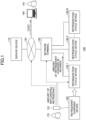
- FIG. 1 is a first diagram illustrating an example of a system configuration of a refrigeration cycle system.
- a refrigeration cycle system 100 includes a server device 110, a network terminal 120, and refrigeration cycle devices 130_1 to 130_N (N is an integer of 2 or more).
- the server device 110 and the network terminal 120 are communicably connected to each other via a network 150.
- the network terminal 120 and the refrigeration cycle devices 130_1 to 130_N are communicably connected to each other via a network (not illustrated).
- the server device 110 manages the refrigeration cycle devices 130_1 to 130_N.
- the server device 110 acquires and manages the amount of refrigerant (initial enclosed amount) enclosed in each of the refrigeration cycle devices 130_1 to 130_N at the time of performing the start-up process of each of the refrigeration cycle devices 130_1 to 130_N that have been installed.
- the refrigerant amount (initial enclosed amount) of the refrigerant enclosed in each of the refrigeration cycle devices 130_1 to 130_N includes:
- the length and thickness of the refrigerant pipe of each of the refrigeration cycle devices 130_1 to 130_N are finally determined by the installation work of a corresponding one of the refrigeration cycle devices 130_1 to 130_N. Therefore, as a result of the installation work, for example, when the length of the refrigerant pipe is longer than the length assumed in advance and the refrigerant needs to be replenished, an operator 170 replenishes the refrigerant on the site using a refrigerant charging device 160. Specifically, the refrigerant is replenished by connecting a refrigerant cylinder included in the refrigerant charging device 160 to a refrigerant replenishment service port provided in the outdoor unit of each of the refrigeration cycle devices 130_1 to 130_N.
- the amount of the refrigerant replenished in this case is measured by the measuring instrument 161.
- the amount of the replenished refrigerant measured by the measuring instrument 161 is manually input to, for example, an operator terminal (not illustrated) owned by the operator 170.
- the amount of the replenished refrigerant is transmitted, via the operator terminal, to the refrigeration cycle devices 130_1 to 130_N, to the network terminal 120, or to the server device 110.
- the server device 110 determines a cost corresponding to the initial enclosed amount for each of the refrigeration cycle devices 130_1 to 130_N based on the acquired initial amount of the enclosed refrigerant.
- the server device 110 stores the initial enclosed amount and the determined cost in association with an identifier for identifying each of the refrigeration cycle devices 130_1 to 130_N.
- the server device 110 can manage the cost determined by the initial enclosed amount as the rental cost for the refrigerant rental.
- the server device 110 transmits the cost determined based on the initial enclosed amount to an owner terminal 140 owned by the owner 141 (an example of a manager) of the refrigeration cycle devices 130_1 to 130_N. Accordingly, the owner 141 of the refrigeration cycle devices 130_1 to 130_N can pay the rental cost for the refrigerant rental to the vendor of the refrigeration cycle devices 130_1 to 130 N.
- the network terminal 120 transmits information received from each of the refrigeration cycle devices 130_1 to 130_N to the server device 110 via the network 150.
- the network terminal 120 transmits the information received from the server device 110 via the network 150 to the refrigeration cycle devices 130_1 to 130_N.
- the network terminal 120 receives the amount of the refrigerant charged in advance from the refrigeration cycle device 130_1, the network terminal 120 transmits the received amount to the server device 110 via the network 150. It is also assumed that the amount of the replenished refrigerant measured by the measuring instrument 161 is transmitted to the refrigeration cycle device 130_1 via the operator terminal (not illustrated) owned by the operator 170. Alternatively, it is assumed that the amount of the replenished refrigerant measured by the measuring instrument 161 is transmitted to the network terminal 120 via the operator terminal (not illustrated) owned by the operator 170. In this case, the network terminal 120 also transmits the amount of the replenished refrigerant to the server device 110.
- the refrigeration cycle devices 130_1 to 130_N are devices that condition air in a target space by using a refrigeration cycle in which thermal energy is circulated. As described above, the refrigeration cycle devices 130_1 to 130_N are charged with the refrigerant in advance, and a necessary amount of the refrigerant is replenished using the refrigerant charging device 160 for refrigerant at the time of installation. When the refrigeration cycle devices 130_1 to 130_N are installed and can communicate with the network terminal 120, the refrigeration cycle devices 130_1 to 130_N transmit the amounts of refrigerant charged in the refrigeration cycle devices in advance to the network terminal 120.
- the refrigeration cycle devices 130_1 to 130_N When the refrigeration cycle devices 130_1 to 130_N are each replenished with a necessary amount of refrigerant using the refrigerant charging device 160 and the amounts of the replenished refrigerant are notified via the operator terminal (not illustrated) owned by the operator 170, the refrigeration cycle devices 130_1 to 130_N receive the notifications. Further, the refrigeration cycle devices 130_1 to 130_N then transmit the received refrigerant amounts (the amount of the replenished refrigerant) to the network terminal 120.
- the owner terminal 140 is a terminal owned by an owner 141 of the refrigeration cycle system 100.
- the owner terminal 140 communicates with the server device 110 via the network 150. Accordingly, the owner terminal 140 receives the cost corresponding to the initial amount of enclosed refrigerant in each of the refrigeration cycle devices 130_1 to 130_N from the server device 110.
- the owner 141 pays the received cost to the company that owns the refrigerant as a rental cost for the refrigerant rental.
- the server device 110 As described above, in the refrigeration cycle system according to the related art, a cost of the refrigerant charged in advance is included in a cost of the refrigeration cycle device, and thus the initial amount of the enclosed refrigerant is not managed.
- the server device 110 according to the first embodiment
- the server device 110 can implement a mechanism for refrigerant rental.
- the refrigeration cycle devices 130_1 to 130_N are all refrigeration cycle devices of the same type, and thus, a schematic configuration of the refrigeration cycle device 130_1 will be described as a representative below.
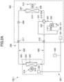
- FIG. 2A is a diagram illustrating an example of a schematic configuration of a refrigeration cycle device.
- the refrigeration cycle device 130_1 mainly includes an outdoor unit 202 and an indoor unit 203.
- the refrigeration cycle device 130_1 also includes a liquid refrigerant communication pipe 206 and a gas refrigerant communication pipe 205 that are refrigerant pipes connecting the outdoor unit 202 and the indoor unit 203, and a controller 207 that controls an operation of the entire refrigeration cycle device 130_1.
- a refrigeration cycle is performed in which the refrigerant charged in a refrigerant circuit 200 is compressed, condensed or dissipates heat, decompressed, evaporated, and then compressed again.
- the refrigerant circuit 200 is charged with a refrigerant for performing a vapor compression refrigeration cycle.
- the refrigerant charged in the refrigerant circuit 200 is at least one of the following refrigerants:
- the outdoor unit 202 is connected to the indoor unit 203 via the liquid refrigerant communication pipe 206 and the gas refrigerant communication pipe 205, and forms a part of the refrigerant circuit 200.
- the outdoor unit 202 mainly includes a compressor 211, a four way switching valve 212, an outdoor heat exchanger 213, an expansion valve 209, an outdoor fan 215, a liquid-side shutoff valve 217, and a gas-side stop valve 216.
- the compressor 211 is a device that compresses a low-pressure refrigerant in the refrigeration cycle until it reaches a high pressure.
- a compressor in which a rotary type or scroll type compression element is rotationally driven by a compressor motor can be used.
- the compressor motor is used to change the capacity, and its operating frequency can be controlled by an inverter.
- the compressor 211 is controlled in rotation speed with a predetermined target evaporation temperature as a target value during cooling operation, and is controlled in rotation speed with a predetermined target condensation temperature as a target value during heating operation, for example.
- the four way switching valve 212 switches following connection states in the refrigerant circuit 200:
- the outdoor heat exchanger 213 is a heat exchanger that functions as a condenser or a radiator of a high-pressure refrigerant in the refrigeration cycle during the cooling operation, and functions as an evaporator of a low-pressure refrigerant in the refrigeration cycle during the heating operation.
- the outdoor heat exchanger 213 includes a plurality of heat transfer tubes (not illustrated) through which the refrigerant flows and a plurality of heat transfer fins (not illustrated) through which air flows.
- the plurality of heat transfer tubes are arranged in the vertical direction, and each heat transfer tube extends substantially in the horizontal direction.
- the plurality of heat transfer fins extending in the vertical direction are arranged at predetermined intervals along the direction in which the heat transfer tube extends.
- the plurality of heat transfer fins and the plurality of heat transfer tubes are combined such that the plurality of heat transfer tubes penetrate each heat transfer fin.
- the outdoor fan 215 supplies outdoor air to the outdoor heat exchanger 213 to exchange heat with the refrigerant in the outdoor heat exchanger 213, and then generates an air flow to discharge the exchanged heat outside the outdoor unit 202.
- the outdoor fan 215 is rotationally driven by an outdoor fan motor.
- the expansion valve 209 is provided between a liquid-side end of the outdoor heat exchanger 213 and the liquid-side shutoff valve 217.
- the expansion valve 209 is, for example, an electronic expansion valve that can adjust a valve opening degree by control.
- the liquid-side shutoff valve 217 is a manual valve disposed at a connection portion with the liquid refrigerant communication pipe 206 in the outdoor unit 202.
- the gas-side stop valve 216 is a manual valve disposed at the connection portion with the gas refrigerant communication pipe 205 in the outdoor unit 202.
- the outdoor unit 202 has an outdoor unit control unit 221 that controls the operations of respective units forming the outdoor unit 202.
- the outdoor unit control unit 221 is connected to an indoor unit control unit 222 of the indoor unit 203 via a communication line, and transmits and receives control signals and the like.
- the outdoor unit 202 is provided with a discharge temperature sensor 225, a suction temperature sensor 226, an outdoor heat exchanger temperature sensor 227, an outdoor air temperature sensor 228, and the like. Each of these sensors is electrically connected to the outdoor unit control unit 221, and transmits a detection signal to the outdoor unit control unit 221.
- the discharge temperature sensor 225 detects the temperature of the refrigerant flowing through the discharge pipe 234 connecting the discharge side of the compressor 211 and one of the connection ports of the four way switching valve 212.
- the suction temperature sensor 226 detects the temperature of the refrigerant flowing through a suction pipe 235 in the suction flow path connecting the suction side of the compressor 211 and one of the connection ports of the four way switching valve 212.
- the outdoor heat exchanger temperature sensor 227 detects the temperature of the refrigerant flowing through the outlet on the liquid side of the outdoor heat exchanger 213 that is the opposite side from the side to which the third pipe 233 is connected.
- the outdoor air temperature sensor 228 detects the temperature of outdoor air before passing through the outdoor heat exchanger 213.
- the indoor unit 203 is installed on a wall surface, a ceiling, or the like in a room that is a target space.
- the indoor unit 203 is connected to the outdoor unit 202 via the liquid refrigerant communication pipe 206 and the gas refrigerant communication pipe 205, and forms a part of the refrigerant circuit 200.
- the indoor unit 203 includes an indoor heat exchanger 218 and an indoor fan 219.
- the liquid side of the indoor heat exchanger 218 is connected to the liquid refrigerant communication pipe 206, and a gas side end of the indoor heat exchanger 218 is connected to the gas refrigerant communication pipe 205.
- the indoor heat exchanger 218 is a heat exchanger that functions as an evaporator of a low-pressure refrigerant in the refrigeration cycle during the cooling operation, and functions as a condenser or a radiator of a high-pressure refrigerant in the refrigeration cycle during the heating operation.
- the indoor fan 219 generates an air flow for suctioning indoor air of a target space into the indoor unit 203, exchanging heat with the refrigerant in the indoor heat exchanger 218, and then discharging the air to the outside of the indoor unit 203.
- the indoor fan 219 is rotationally driven by an indoor fan motor.
- the indoor unit 203 also includes the indoor unit control unit 222 that controls the operation of each unit forming the indoor unit 203.
- the indoor unit control unit 222 is connected to the outdoor unit control unit 221 via a communication line, and transmits and receives control signals and the like.
- the indoor unit 203 is provided with an indoor liquid side heat exchanger temperature sensor 223, an indoor air temperature sensor 224, and the like. Each of these sensors is electrically connected to the indoor unit control unit 222.
- the indoor liquid side heat exchanger temperature sensor 223 detects the temperature of the refrigerant flowing through the outlet on the liquid side of the indoor heat exchanger 218 that is the opposite side from the side to which the gas refrigerant communication pipe 205 is connected.
- the indoor air temperature sensor 224 detects the temperature of the indoor air before passing through the indoor heat exchanger 218.
- FIG. 2B is a diagram illustrating an example of a system configuration of the refrigeration cycle device.
- the controller 207 is configured by connecting the outdoor unit control unit 221 and the indoor unit control unit 222 via a communication line.
- the remote controller 220 is disposed in a room as a target space or in a specific space of a building including the target space, and is used by a user or the like to issue an operation control instruction to the refrigeration cycle device 130_1 or to monitor the operation state of the refrigeration cycle device 130_1.
- the remote controller 220 includes a reception unit 220a such as an operation button or a touch panel that receives input of information by being operated by a user or the like, and a display 220b that can display various kinds of information.
- the remote controller 220 is connected to the outdoor unit control unit 221 and the indoor unit control unit 222 via a communication line, and can supply information received from the user at the reception unit 220a to the controller 207. Further, information received from the controller 207 can be output on the display 220b.
- the information received by the reception unit 220a from the user or the like is not particularly specified, but various kinds of information such as an instruction to execute a cooling operation mode, an instruction to execute a heating operation mode, an instruction to stop the operation, and designation of a setting temperature are exemplified.
- the information displayed on the display 220b is not particularly specified, but may include information indicating the current state of the operation mode (cooling or heating), the setting temperature, and the occurrence of various abnormalities.
- each device here, the server device 110, the network terminal 120, and the controller 207) forming the refrigeration cycle system 100 will be described.
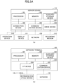
- FIG. 3A is a diagram illustrating an example of a hardware configuration of the server device and the network terminals.
- the server device 110 includes a processor 301, a memory 302, an auxiliary storage device 303, a connection device 304, a communication device 305, and a drive device 306.
- the hardware components of the server device 110 are connected to each other via a bus 307.
- the processor 301 includes various computing devices such as a central processing unit (CPU).
- the processor 301 loads various programs (for example, a management program) onto the memory 302 and executes the programs.
- programs for example, a management program
- the memory 302 includes a main storage device such as a read only memory (ROM) or a random access memory (RAM).
- the processor 301 and the memory 302 form a so-called computer (also referred to as a "control unit” or a “second control unit"), and the processor 301 executes various programs loaded on the memory 302, whereby the computer implements various functions.
- the auxiliary storage device 303 stores various programs and various kinds of information used when the various programs are executed by the processor 301.
- connection device 304 connects an operation device 310 and the display device 311 to the server device 110.
- the communication device 305 is a device for connecting to the network 150 and communicating with the network terminal 120 or the owner terminal 140.
- the drive device 306 is a device for setting a recording medium 312.
- the recording medium 312 includes a medium for optically, electrically, or magnetically recording information, such as a CD-ROM, a flexible disk, or a magneto-optical disk.
- the recording medium 312 may include a semiconductor memory or the like that electrically records information, such as a ROM or a flash memory.
- the various programs installed in the auxiliary storage device 303 are installed by, for example, setting the distributed recording medium 312 in the drive device 306 and reading the various programs recorded in the recording medium 312 by the drive device 306.
- the various programs installed in the auxiliary storage device 303 may be installed by being downloaded from the network 150 via the communication device 305.
- the network terminal 120 includes a processor 321, a memory 322, an auxiliary storage device 323, an interface (I/F) device 324, and a communication device 325.
- the hardware components of the network terminal 120 are connected to each other via a bus 326.
- the processor 321 to the auxiliary storage device 323 and the communication device 325 are the same as the processor 301 to the auxiliary storage device 303 and the communication device 305 of the server device 110, respectively, and thus the description thereof will be omitted here.
- the processor 321 and the memory 322 form a so-called computer (also referred to as a "first control unit").
- the processor 321 executes the various programs read out onto the memory 322, whereby the computer implements various functions.
- the I/F device 324 connects the refrigeration cycle devices 130_1 to 130_N to the network terminal 120.
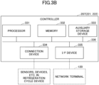
- FIG. 3B is a diagram illustrating an example of a hardware configuration of a controller of the refrigeration cycle device.
- the outdoor unit control unit 221 and the indoor unit control unit 222 forming the controller 207 each include a processor 331, a memory 332, an auxiliary storage device 333, a connection device 334, and an I/F device 335.
- the hardware of the outdoor unit control unit 221 and the indoor unit control unit 222 forming the controller 207 are connected to each other via a bus 336.
- the processor 331 to the auxiliary storage device 333 and the I/F device 335 are the same as the processor 321 to the auxiliary storage device 323 and the I/F device 324 of the network terminal 120, respectively, and thus the description thereof will be omitted here.
- the processor 331 and the memory 332 form a so-called computer (also referred to as a "first control unit").
- the processor 331 executes the various programs loaded on the memory 332, whereby the computer implements various functions.
- connection device 334 connects the sensors, devices, and the like in the refrigeration cycle device 130_1 to the outdoor unit control unit 221 and the indoor unit control unit 222 forming the controller 207.
- a management program is installed in the server device 110, and the server device 110 functions as a refrigerant amount acquisition unit 401, a cost determination unit 402, a notification unit 403, a payment information acquisition unit 411, and an operation management unit 412 by executing the program.
- the refrigerant amount acquisition unit 401 acquires the amount (initial enclosed amount) of the refrigerant enclosed in each of the refrigeration cycle devices 130_1 to 130_N in association with an identifier for identifying a corresponding one of the refrigeration cycle devices 130_1 to 130_N.
- the amount (initial enclosed amount) of the refrigerant enclosed in each of the refrigeration cycle devices 130_1 to 130_N includes:
- a method of acquiring the initial amount of enclosed refrigerant by the refrigerant amount acquisition unit 401 includes:
- the refrigerant amount acquisition unit 401 notifies the cost determination unit 402 of the acquired initial amount of enclosed refrigerant and the identifier of the refrigeration cycle device.
- the cost determination unit 402 stores the initial enclosed amount and the identifier notified by the refrigerant amount acquisition unit 401 in a cost storage unit 404.
- the cost determination unit 402 calculates the cost corresponding to the initial amount of enclosed refrigerant by multiplying the initial amount of enclosed refrigerant notified by the refrigerant amount acquisition unit 401 by the unit price per unit amount of refrigerant, and stores the cost in the cost storage unit 404. In this case, it is assumed that the unit price per unit amount of the refrigerant is set in advance in the cost determination unit 402.
- the cost determination unit 402 derives the cost corresponding to the initial amount of enclosed refrigerant by comparing the initial amount of enclosed refrigerant notified by the refrigerant amount acquisition unit 401 with a table defining the relationship between the amount of refrigerant and the amount of money, and stores the cost in the cost storage unit 404.
- the cost determination unit 402 holds in advance a table in which the amount of money is assigned to each range of the amount of refrigerant, for example, "XX yen" for "range from 5kg to 10kg".
- the cost determination unit 402 reads the cost corresponding to the initial amount of enclosed refrigerant and the identifier of the refrigeration cycle device from the cost storage unit 404 at an appropriate timing when the start-up process of the refrigeration cycle devices 130_1 to 130_N is performed, and notifies the notification unit 403 of the cost and the identifier.
- the notification unit 403 transmits the cost corresponding to the initial amount of the refrigerant and the identifier of the refrigeration cycle device to the owner terminal 140 of the owner 141 of the refrigeration cycle device 130_1 to 130_N, and prompts the owner to pay the rental cost for the refrigerant rental.
- the notification unit 403 notifies the payment information acquisition unit 411 of the cost corresponding to the initial amount of enclosed refrigerant and the identifier of the refrigeration cycle device.
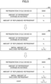
- FIG. 5 is a first diagram illustrating a specific example of a cost calculation process performed by the refrigerant amount acquisition unit, the cost determination unit, and the notification unit of the server device.
- a specific example of the cost calculation process for the refrigeration cycle device 130_1 is illustrated.
- the refrigerant amount acquisition unit 401 acquires:
- the payment information acquisition unit 411 acquires a notification of payment completion when the owner 141 pays the rental cost for the refrigerant rental in response to the notification unit 403 transmitting the cost corresponding to the initial amount of the enclosed refrigerant to the owner terminal 140.
- the payment information acquisition unit 411 acquires the notification of completion of payment of the rental cost for the refrigerant rental for each of the refrigeration cycle devices 130_1 to 130_N from a transfer destination institution or the like.
- the payment information acquisition unit 411 stores the notification of the payment completion in a payment information storage unit 413.
- the operation management unit 412 determines whether to permit the operation of each of the refrigeration cycle devices 130_1 to 130_N based on the notification of the payment completion stored in the payment information storage unit 413.
- the operation management unit 412 monitors a payment status of the owner 141 by accessing the payment information storage unit 413 at a predetermined cycle, for example, and permits the refrigeration cycle device for which the payment has been completed to operate.
- each of the refrigeration cycle devices 130_1 to 130_N accesses the operation management unit 412, and performs control to start the operation upon the operation being permitted, or performs control not to start the operation upon the operation being not permitted.
- the operation management unit 412 may transmit a determination result (permitted or not permitted) as to whether to permit the operation to each of the refrigeration cycle devices 130_1 to 130_N.
- the refrigeration cycle devices 130_1 to 130_N receive an instruction to start operation
- the refrigeration cycle devices 130_1 to 130_N start operation upon receiving a notification of "permitted”
- control not to start operation upon receiving a notification of "not permitted”.
- the operation management unit 412 may notify a determination result (permitted or not permitted) as to whether to permit the operation to the operator terminal (not illustrated) of the operator 170, and the operator 170 may directly set the refrigeration cycle devices 130_1 to 130_N to be operable or inoperable.
- FIG. 6 is a diagram illustrating a specific example of an operation permission/rejection management process by the payment information acquisition unit and the operation management unit of the server device.
- a specific example of the operation permission/inhibition management process for the refrigeration cycle device 130_1 is illustrated.
- the payment information acquisition unit 411 updates the payment status to "payment completed" as indicated by a reference numeral 602.
- the operation management unit 412 accesses the payment information storage unit 413 at a predetermined cycle to check the payment status and holds the determination result of the permission or rejection of the operation.
- a reference numeral 611 in (b) of FIG. 6 indicates a determination result in a case where the payment information storage unit 413 is accessed at a timing at which the payment status indicated by the reference numeral 601 is stored. In this case, the operation management unit 412 determines that the operation is not permitted, and thus "not permitted" is held in the operation permission/rejection as indicated by the reference numeral 611.
- a reference numeral 612 in (b) of FIG. 6 indicates a determination result in a case where access is made at a timing at which the payment status indicated by the reference numeral 602 is stored in the payment information storage unit 413.
- the operation management unit 412 determines that the operation is permitted, and thus "permitted" is held in the operation permission/rejection as indicated by the reference numeral 612.
- the operation management unit 412 permits the operation of the refrigeration cycle device on condition that the rental cost for the refrigerant rental has been paid in response to the transmission of the cost corresponding to the initial amount of enclosed refrigerant.
- FIG. 7 is an example of a first sequence diagram illustrating a series of processes of the refrigeration cycle system.
- step S701 the operator 170 replenishes the refrigeration cycle devices 130_1 to 130_N with the refrigerant using the refrigerant charging device 160, and measures the amount of the replenished refrigerant.
- the operator 170 also transmits the amount of the replenished refrigerant to the server device 110 in association with the identifier of each of the refrigeration cycle devices 130_1 to 130_N.
- the operator 170 transmits the amount of the replenished refrigerant and the identifier to the server device 110 by using the operator terminal 720.
- the operator 170 transmits the amount of the replenished refrigerant and the identifier to the server device 110 via the network terminal 120 by using the operator terminal 720.
- the operator 170 transmits the amount of the replenished refrigerant and the identifier to the server device 110 via the refrigeration cycle devices 130_1 to 130_N and the network terminal 120 by using the operator terminal 720.
- step S702 the refrigeration cycle devices 130_1 to 130_N each transmit the amount of the refrigerant charged in advance to the server device 110 via the network terminals 120.
- step S703 the server device 110 acquires the initial amount of enclosed refrigerant in each of the refrigeration cycle devices 130_1 to 130_N.
- step S704 the server device 110 determines the cost corresponding to the initial amount of enclosed refrigerant, and stores the cost in the cost storage unit 404.
- step S705 the server device 110 stores default information ("not yet") in the payment status and holds default information (“not permitted”) in the operation permission/rejection in the payment information storage unit 413.
- step S706 the refrigeration cycle devices 130_1 to 130_N perform a start-up process.
- step S707 the refrigeration cycle devices 130_1 to 130_N determine whether an instruction to start operation has been received.
- the process waits until the instruction to start the operation is received.
- the refrigeration cycle devices 130_1 to 130_N each determine in step S707 that the instruction to start the operation has been received (YES in step S707), the process proceeds to step S713.
- step S708 the server device 110 transmits the identifiers of the refrigeration cycle devices 130_1 to 130_N and the cost corresponding to the initial amount of the enclosed refrigerant to the owner terminal 140.
- step S709 the owner 141 having the owner terminal 140 pays the rental cost for the refrigerant rental by transferring the rental cost to the transfer destination institution 710 or the like.
- step S710 the transfer destination institution 710 or the like notifies the server device 110 that the payment of the cost by the owner 141 has been completed.
- step S711 in response to the acquisition of the notification of the payment completion, the server device 110 updates "not yet" stored in the payment status of the payment information storage unit 413 to "payment completed".
- step S712 the server device 110 updates "not permitted” held in the operation permission/rejection to "permitted” in response to the update of the payment status.
- the server device 110 according to the first embodiment
- the server device 110 manages the initial amount of enclosed refrigerant that should be managed at the time of refrigerant rental, and determines the rental cost that should be determined at the time of refrigerant rental before the start of operation.
- the server device 110 according to the first embodiment can implement a mechanism for refrigerant rental.
- the amount of the refrigerant replenished to each of the refrigeration cycle devices 130_1 to 130_N by using the refrigerant charging device 160 is transmitted via the operator terminal 720 of the operator 170.
- the method by which the server device 110 acquires the initial amount of enclosed refrigerant is not limited to this method.
- each of the refrigeration cycle devices 130_1 to 130_N measures the amount of refrigerant in the refrigeration cycle devices 130_1 to 130_N.
- the server device 110 can acquire the amount of the refrigerant measured by each of the refrigeration cycle devices 130_1 to 130_N as the initial enclosed amount.
- FIG. 8 is a second diagram illustrating an example of the system configuration of the refrigeration cycle system. The differences from the system configuration described using FIG. 1 in the first embodiments are as follows:
- FIG. 9 is a second diagram illustrating a specific example of the cost calculation process performed by the refrigerant amount acquisition unit, the cost determination unit, and the notification unit of the server device.
- the refrigerant amount acquisition unit 401 acquires:
- FIG. 10 is an example of a second sequence diagram illustrating a series of processes of the refrigeration cycle system.
- the differences from the first sequence diagram in the first embodiment that will be described with reference to FIG. 10 are steps S1001 to S1003.
- step S1001 the refrigeration cycle devices 130_1 to 130_N perform a start-up process.
- step S1003 the refrigeration cycle devices 130_1 to 130_N each transmit the measured amount of the refrigerant as the initial amount of the enclosed refrigerant to the server device 110 via the network terminals 120.
- the server device 110 can implement a refrigerant rental mechanism, as in the first embodiment.
- the first embodiment describes that all the refrigerants enclosed in the refrigeration cycle devices 130_1 to 130_N in advance are used even during the operation at the time of installing the refrigeration cycle devices 130_1 to 130_N. However, not all the refrigerants enclosed in the refrigeration cycle devices 130_1 to 130_N in advance are used even during operation, and there are cases where part of the refrigerant is not used.
- the refrigeration cycle devices 130_1 to 130_N are charged with the amount of refrigerant corresponding to the refrigerant pipe length of Lm in advance.
- the pipe length of the refrigerant pipe may be shorter than Lm.
- part of the refrigerant charged in advance in the refrigeration cycle devices 130_1 to 130_N is not used, and is stored in, for example, a container.
- the operator 170 transmits the amount of the refrigerant to be actually used to the refrigeration cycle device 130_1, the network terminal 120, or the server device 110 via the operator terminal 720.
- the refrigeration cycle devices 130_1 to 130_N each transmit the amount of the refrigerant charged in advance to the server device 110 via the network terminal 120.
- the method of transmitting the amount of the refrigerant charged in advance to the server device 110 is not limited to this example, and for example, an administrator of the server device 110 may input the amount of the refrigerant to the server device 110 via the operation device 310.
- the notification unit 403 transmits the cost corresponding to the initial amount of enclosed refrigerant in each refrigeration cycle device to the owner terminal 140.
- the method of transmission to the owner terminal 140 is not limited to this, and for example, the costs corresponding to the initial enclosed amounts of the refrigerant of the plurality of refrigeration cycle devices 130_1 to 130_N may be added up and transmitted to the owner terminal 140.
- controller 207 functions of the controller 207 in the case where the operator 170 transmits the amount of the replenished refrigerant to, for example, the refrigeration cycle device 130_1 are not described.
- the controller 207 may execute, for example, a plurality of modes.
- the controller 207 may execute the start-up mode.
- the controller 207 transmits the amount of refrigerant charged in the refrigeration cycle device 130_1 in advance to the server device 110 via the network terminal 120 together with the identifier of the refrigeration cycle device 130_1.
- the amount of the replenished refrigerant is received by communicating with an operator terminal 720 owned by the operator 170. Further, the received refrigerant amount is transmitted to the server device 110 via the network terminal 120 together with the identifier of the refrigeration cycle device 130_1.
- the refrigeration cycle device 130_1 can transmit the initial amount of enclosed refrigerant (the amount of refrigerant charged in advance and the amount of replenished refrigerant) to the server device 110 in association with the identifier of the refrigeration cycle device 130_1.
- the refrigeration cycle devices 130_1 to 130_N are replenished with the refrigerant.
- the refrigeration cycle system 100 includes the plurality of refrigeration cycle devices 130_1 to 130_N.
- the refrigeration cycle system 100 may include one refrigeration cycle device.
- the plurality of refrigeration cycle devices 130_1 to 130_N communicate with the server device 110 via the network terminal 120 via the network terminal 120.
- the plurality of refrigeration cycle devices 130_1 to 130_N may communicate with the server device 110 without the network terminal 120.
Landscapes
- Engineering & Computer Science (AREA)
- Business, Economics & Management (AREA)
- Physics & Mathematics (AREA)
- Economics (AREA)
- Strategic Management (AREA)
- Health & Medical Sciences (AREA)
- General Physics & Mathematics (AREA)
- Human Resources & Organizations (AREA)
- Marketing (AREA)
- Theoretical Computer Science (AREA)
- General Business, Economics & Management (AREA)
- Tourism & Hospitality (AREA)
- Water Supply & Treatment (AREA)
- Thermal Sciences (AREA)
- General Engineering & Computer Science (AREA)
- Public Health (AREA)
- Mechanical Engineering (AREA)
- General Health & Medical Sciences (AREA)
- Primary Health Care (AREA)
- Entrepreneurship & Innovation (AREA)
- Finance (AREA)
- Development Economics (AREA)
- Accounting & Taxation (AREA)
- Game Theory and Decision Science (AREA)
- Operations Research (AREA)
- Quality & Reliability (AREA)
- Air Conditioning Control Device (AREA)
- Management, Administration, Business Operations System, And Electronic Commerce (AREA)
Abstract
Description
- The present disclosure relates to a server device, a refrigeration cycle system, a management method, and a management program.
- In the worldwide regulation of chlorofluorocarbons, refrigerants using chlorofluorocarbons are expected to be depleted of raw materials, and market prices thereof are currently rising. Therefore, in the refrigeration cycle systems, it is required to efficiently recycle the refrigerant.
- As a mechanism for efficiently recycling the refrigerant, for example, a mechanism for renting the refrigerant to a user of the refrigeration cycle system is considered. This is because, in the refrigeration cycle system, the amount of refrigerant can be easily managed by separating a device from the refrigerant.
- Meanwhile, various techniques have been proposed as management techniques for managing the amount of refrigerant.
- Patent Document 1:
WO 2019/234824 - However, the related art management techniques appear to be a technique that focuses on a decrease in refrigeration capacity due to a decrease in the amount of refrigerant after the start of operation, and does not manage the initial amount of enclosed refrigerant, which should be managed when the refrigerant is rented. Therefore, the related art management techniques do not appear to determine the rental cost that should be determined at the time of the refrigerant rental before the start of the operation.
- The present disclosure provides a server device, a refrigeration cycle system, a management method, and a management program that implement a scheme of refrigerant rental.
- A first aspect of the present disclosure is a server device that includes:
- a control unit; and
- a storage unit, where the control unit
- acquires an amount of refrigerant enclosed in a refrigeration cycle device and an identifier for identifying the refrigeration cycle device,
- determines a cost corresponding to the amount of refrigerant, and
- stores, in the storage unit, the amount of refrigerant, the cost, and the identifier in association with each other.
- According to the first aspect of the present disclosure, it is possible to provide a server device that implements a mechanism of refrigerant rental.
- A second aspect of the present disclosure is the server device according to the first aspect, where the control unit notifies a manager of the refrigeration cycle device of the cost.
- A third aspect of the present disclosure is the server device according to the first or second aspect, where the control unit acquires an amount of refrigerant used in the refrigeration cycle device, out of the amount of refrigerant enclosed in the refrigeration cycle device before a start of operation of the refrigeration cycle device.
- A fourth aspect of the present disclosure is the server device according to the third aspect, where the amount of refrigerant enclosed in the refrigeration cycle device includes
- an amount of refrigerant charged in the refrigeration cycle device in advance before the refrigeration cycle device is installed, and
- an amount of replenished refrigerant before operation is started, the refrigeration cycle device being installed.
- A fifth aspect of the present disclosure is the server device according to any one of the first to fourth aspects,
- where the control unit permits an operation of the refrigeration cycle device on condition that the cost has been paid, and
- where the refrigeration cycle device starts operation when the operation is permitted.
- A sixth aspect of the present disclosure is a refrigeration cycle system that includes:
- a first control unit configured to manage a refrigeration cycle device; and
- a server device including a second control unit and a storage unit, the second control unit being configured to communicate with the first control unit,
- where the second control unit
- acquires, via the first control unit, an amount of refrigerant enclosed in the refrigeration cycle device and an identifier for identifying the refrigeration cycle device,
- determines a cost corresponding to the amount of refrigerant, and
- stores, in the storage unit, the amount of refrigerant, the cost, and the identifier in association with each other.
- According to the sixth aspect of the present disclosure, it is possible to provide a refrigeration cycle system that implements a mechanism for refrigerant rental.
- A seventh aspect of the present disclosure is the refrigeration cycle system according to the sixth aspect, where the refrigeration cycle device measures the amount of refrigerant enclosed therein, and transmits the measured amount of refrigerant to the second control unit via the first control unit in association with the identifier.
- An eighth aspect of the present disclosure is the refrigeration cycle system according to the sixth or seventh aspect, where the amount of the refrigerant enclosed in the refrigeration cycle device includes
- an amount of the refrigerant charged in the refrigeration cycle device in advance before the refrigeration cycle device is installed, and
- an amount of the refrigerant replenished before operation is started, the refrigeration cycle device being installed.
- A ninth aspect of the present disclosure is a management method that includes
causing a control unit to: - acquire an amount of refrigerant enclosed in a refrigeration cycle device and an identifier for identifying the refrigeration cycle device;
- determine a cost corresponding to the amount of refrigerant; and
- store the amount of refrigerant, the cost, and the identifier in a storage unit in association with each other.
- According to the ninth aspect of the present disclosure, it is possible to provide a management method for implementing a mechanism of refrigerant rental.
- A tenth aspect of the present disclosure is a management program for causing a control unit to execute a process, where the process includes:
- acquiring an amount of a refrigerant enclosed in a refrigeration cycle device and an identifier for identifying the refrigeration cycle device;
- determining a cost corresponding to the amount of refrigerant; and
- storing the amount of refrigerant, the cost, and the identifier in a storage unit in association with each other.
- According to the tenth aspect of the present disclosure, it is possible to provide a management program for implementing a mechanism of refrigerant rental.
-
- [
FIG. 1] FIG.1 is a first diagram illustrating an example of a system configuration of a refrigeration cycle system. - [
FIG. 2A] FIG.2A is a diagram illustrating an example of a schematic configuration of a refrigeration cycle device. - [
FIG. 2B] FIG.2B is a diagram illustrating an example of a system configuration of the refrigeration cycle device. - [
FIG. 3A] FIG.3A is a diagram illustrating an example of hardware configurations of a server device and a network terminal. - [
FIG. 3B] FIG.3B is a diagram illustrating an example of a hardware configuration of a controller of the refrigeration cycle device. - [
FIG. 4] FIG.4 is a diagram illustrating an example of a functional configuration of the server device. - [
FIG. 5] FIG.5 is a first diagram illustrating a specific example of a cost calculation process by a refrigerant amount acquisition unit, a cost determination unit, and a notification unit of the server device. - [
FIG. 6] FIG.6 is a diagram illustrating a specific example of an operation permission/rejection management process by a payment information acquisition unit and an operation management unit of the server device. - [
FIG. 7] FIG.7 is an example of a first sequence diagram illustrating a series of processes of the refrigeration cycle system. - [
FIG. 8] FIG.8 is a second diagram illustrating an example of a system configuration of a refrigeration cycle system. - [
FIG. 9] FIG.9 is a second diagram illustrating a specific example of a cost calculation process by a refrigerant amount acquisition unit, a cost determination unit, and a notification unit of a server device. - [
FIG. 10] FIG.10 is an example of a second sequence diagram illustrating a series of processes of the refrigeration cycle system. - Hereinafter, each embodiment will be described with reference to the accompanying drawings. In the present specification and drawings, components having substantially the same functional configuration are denoted by the same reference numerals, and redundant description will be omitted.
- First, a system configuration of a refrigeration cycle system according to a first embodiment will be described.
FIG. 1 is a first diagram illustrating an example of a system configuration of a refrigeration cycle system. As illustrated inFIG. 1 , arefrigeration cycle system 100 includes aserver device 110, anetwork terminal 120, and refrigeration cycle devices 130_1 to 130_N (N is an integer of 2 or more). - In the
refrigeration cycle system 100, theserver device 110 and thenetwork terminal 120 are communicably connected to each other via anetwork 150. In therefrigeration cycle system 100, thenetwork terminal 120 and the refrigeration cycle devices 130_1 to 130_N are communicably connected to each other via a network (not illustrated). - The
server device 110 manages the refrigeration cycle devices 130_1 to 130_N. In the first embodiment, theserver device 110 acquires and manages the amount of refrigerant (initial enclosed amount) enclosed in each of the refrigeration cycle devices 130_1 to 130_N at the time of performing the start-up process of each of the refrigeration cycle devices 130_1 to 130_N that have been installed. - At the time of performing the start-up process, the refrigerant amount (initial enclosed amount) of the refrigerant enclosed in each of the refrigeration cycle devices 130_1 to 130_N includes:
- an amount of the refrigerant charged in each of the refrigeration cycle devices 130_1 to 130_N in advance before a corresponding one of the refrigeration cycle devices 130_1 to 130_N is installed; and
- an amount of the refrigerant replenished before the operation is started, with each of the refrigeration cycle devices 130_1 to 130_N being installed.
- The length and thickness of the refrigerant pipe of each of the refrigeration cycle devices 130_1 to 130_N are finally determined by the installation work of a corresponding one of the refrigeration cycle devices 130_1 to 130_N. Therefore, as a result of the installation work, for example, when the length of the refrigerant pipe is longer than the length assumed in advance and the refrigerant needs to be replenished, an
operator 170 replenishes the refrigerant on the site using arefrigerant charging device 160. Specifically, the refrigerant is replenished by connecting a refrigerant cylinder included in therefrigerant charging device 160 to a refrigerant replenishment service port provided in the outdoor unit of each of the refrigeration cycle devices 130_1 to 130_N. - The amount of the refrigerant replenished in this case is measured by the measuring
instrument 161. The amount of the replenished refrigerant measured by the measuringinstrument 161 is manually input to, for example, an operator terminal (not illustrated) owned by theoperator 170. Thus, the amount of the replenished refrigerant is transmitted, via the operator terminal, to the refrigeration cycle devices 130_1 to 130_N, to thenetwork terminal 120, or to theserver device 110. - The
server device 110 determines a cost corresponding to the initial enclosed amount for each of the refrigeration cycle devices 130_1 to 130_N based on the acquired initial amount of the enclosed refrigerant. Theserver device 110 stores the initial enclosed amount and the determined cost in association with an identifier for identifying each of the refrigeration cycle devices 130_1 to 130_N. Thus, theserver device 110 can manage the cost determined by the initial enclosed amount as the rental cost for the refrigerant rental. - The
server device 110 transmits the cost determined based on the initial enclosed amount to anowner terminal 140 owned by the owner 141 (an example of a manager) of the refrigeration cycle devices 130_1 to 130_N. Accordingly, theowner 141 of the refrigeration cycle devices 130_1 to 130_N can pay the rental cost for the refrigerant rental to the vendor of the refrigeration cycle devices 130_1 to 130 N. - The
network terminal 120 transmits information received from each of the refrigeration cycle devices 130_1 to 130_N to theserver device 110 via thenetwork 150. Thenetwork terminal 120 transmits the information received from theserver device 110 via thenetwork 150 to the refrigeration cycle devices 130_1 to 130_N. - For example, it is assumed that when the
network terminal 120 receives the amount of the refrigerant charged in advance from the refrigeration cycle device 130_1, thenetwork terminal 120 transmits the received amount to theserver device 110 via thenetwork 150. It is also assumed that the amount of the replenished refrigerant measured by the measuringinstrument 161 is transmitted to the refrigeration cycle device 130_1 via the operator terminal (not illustrated) owned by theoperator 170. Alternatively, it is assumed that the amount of the replenished refrigerant measured by the measuringinstrument 161 is transmitted to thenetwork terminal 120 via the operator terminal (not illustrated) owned by theoperator 170. In this case, thenetwork terminal 120 also transmits the amount of the replenished refrigerant to theserver device 110. - The refrigeration cycle devices 130_1 to 130_N are devices that condition air in a target space by using a refrigeration cycle in which thermal energy is circulated. As described above, the refrigeration cycle devices 130_1 to 130_N are charged with the refrigerant in advance, and a necessary amount of the refrigerant is replenished using the
refrigerant charging device 160 for refrigerant at the time of installation. When the refrigeration cycle devices 130_1 to 130_N are installed and can communicate with thenetwork terminal 120, the refrigeration cycle devices 130_1 to 130_N transmit the amounts of refrigerant charged in the refrigeration cycle devices in advance to thenetwork terminal 120. When the refrigeration cycle devices 130_1 to 130_N are each replenished with a necessary amount of refrigerant using therefrigerant charging device 160 and the amounts of the replenished refrigerant are notified via the operator terminal (not illustrated) owned by theoperator 170, the refrigeration cycle devices 130_1 to 130_N receive the notifications. Further, the refrigeration cycle devices 130_1 to 130_N then transmit the received refrigerant amounts (the amount of the replenished refrigerant) to thenetwork terminal 120. - The
owner terminal 140 is a terminal owned by anowner 141 of therefrigeration cycle system 100. Theowner terminal 140 communicates with theserver device 110 via thenetwork 150. Accordingly, theowner terminal 140 receives the cost corresponding to the initial amount of enclosed refrigerant in each of the refrigeration cycle devices 130_1 to 130_N from theserver device 110. Theowner 141 pays the received cost to the company that owns the refrigerant as a rental cost for the refrigerant rental. - As described above, in the refrigeration cycle system according to the related art, a cost of the refrigerant charged in advance is included in a cost of the refrigeration cycle device, and thus the initial amount of the enclosed refrigerant is not managed. However, the
server device 110 according to the first embodiment - manages an initial amount of enclosed refrigerant in the refrigerant rental; and
- determines the rental cost that should be determined at the time of refrigerant rental before the operation is started.
- As a result, the
server device 110 according to the first embodiment can implement a mechanism for refrigerant rental. - Next, a schematic configuration of the refrigeration cycle devices 130_1 to 130_N will be described. In the first embodiment, the refrigeration cycle devices 130_1 to 130_N are all refrigeration cycle devices of the same type, and thus, a schematic configuration of the refrigeration cycle device 130_1 will be described as a representative below.
-
FIG. 2A is a diagram illustrating an example of a schematic configuration of a refrigeration cycle device. As illustrated inFIG. 2A , the refrigeration cycle device 130_1 mainly includes anoutdoor unit 202 and anindoor unit 203. The refrigeration cycle device 130_1 also includes a liquidrefrigerant communication pipe 206 and a gasrefrigerant communication pipe 205 that are refrigerant pipes connecting theoutdoor unit 202 and theindoor unit 203, and acontroller 207 that controls an operation of the entire refrigeration cycle device 130_1. - In the refrigeration cycle device 130_1, a refrigeration cycle is performed in which the refrigerant charged in a
refrigerant circuit 200 is compressed, condensed or dissipates heat, decompressed, evaporated, and then compressed again. In the first embodiment, therefrigerant circuit 200 is charged with a refrigerant for performing a vapor compression refrigeration cycle. - The refrigerant charged in the
refrigerant circuit 200 is at least one of the following refrigerants: - a mixed refrigerant containing 1,2-difluoroethylene and one or more hydrofluorocarbons;
- a mixed refrigerant containing 1,2-difluoroethylene and one or more hydrofluoroolefins; and
- a mixed refrigerant containing one or more hydrofluorocarbons and one or more hydrofluoroolefins.
- The
outdoor unit 202 is connected to theindoor unit 203 via the liquidrefrigerant communication pipe 206 and the gasrefrigerant communication pipe 205, and forms a part of therefrigerant circuit 200. Theoutdoor unit 202 mainly includes acompressor 211, a fourway switching valve 212, anoutdoor heat exchanger 213, anexpansion valve 209, anoutdoor fan 215, a liquid-side shutoff valve 217, and a gas-side stop valve 216. - The
compressor 211 is a device that compresses a low-pressure refrigerant in the refrigeration cycle until it reaches a high pressure. As thecompressor 211, for example, a compressor in which a rotary type or scroll type compression element is rotationally driven by a compressor motor can be used. The compressor motor is used to change the capacity, and its operating frequency can be controlled by an inverter. Thecompressor 211 is controlled in rotation speed with a predetermined target evaporation temperature as a target value during cooling operation, and is controlled in rotation speed with a predetermined target condensation temperature as a target value during heating operation, for example. - The four
way switching valve 212 switches following connection states in the refrigerant circuit 200: - a first connection state in which a suction side of the
compressor 211 and the gas-side stop valve 216 are connected while a discharge side of thecompressor 211 and theoutdoor heat exchanger 213 are connected; and - a second connection state in which the suction side of the
compressor 211 and theoutdoor heat exchanger 213 are connected while the discharge side of thecompressor 211 and the gas-side stop valve 216 are connected. - The
outdoor heat exchanger 213 is a heat exchanger that functions as a condenser or a radiator of a high-pressure refrigerant in the refrigeration cycle during the cooling operation, and functions as an evaporator of a low-pressure refrigerant in the refrigeration cycle during the heating operation. Theoutdoor heat exchanger 213 includes a plurality of heat transfer tubes (not illustrated) through which the refrigerant flows and a plurality of heat transfer fins (not illustrated) through which air flows. The plurality of heat transfer tubes are arranged in the vertical direction, and each heat transfer tube extends substantially in the horizontal direction. The plurality of heat transfer fins extending in the vertical direction are arranged at predetermined intervals along the direction in which the heat transfer tube extends. The plurality of heat transfer fins and the plurality of heat transfer tubes are combined such that the plurality of heat transfer tubes penetrate each heat transfer fin. - The
outdoor fan 215 supplies outdoor air to theoutdoor heat exchanger 213 to exchange heat with the refrigerant in theoutdoor heat exchanger 213, and then generates an air flow to discharge the exchanged heat outside theoutdoor unit 202. Theoutdoor fan 215 is rotationally driven by an outdoor fan motor. - The
expansion valve 209 is provided between a liquid-side end of theoutdoor heat exchanger 213 and the liquid-side shutoff valve 217. Theexpansion valve 209 is, for example, an electronic expansion valve that can adjust a valve opening degree by control. - The liquid-
side shutoff valve 217 is a manual valve disposed at a connection portion with the liquidrefrigerant communication pipe 206 in theoutdoor unit 202. - The gas-
side stop valve 216 is a manual valve disposed at the connection portion with the gasrefrigerant communication pipe 205 in theoutdoor unit 202. - The
outdoor unit 202 has an outdoorunit control unit 221 that controls the operations of respective units forming theoutdoor unit 202. The outdoorunit control unit 221 is connected to an indoorunit control unit 222 of theindoor unit 203 via a communication line, and transmits and receives control signals and the like. - The
outdoor unit 202 is provided with adischarge temperature sensor 225, asuction temperature sensor 226, an outdoor heatexchanger temperature sensor 227, an outdoorair temperature sensor 228, and the like. Each of these sensors is electrically connected to the outdoorunit control unit 221, and transmits a detection signal to the outdoorunit control unit 221. Thedischarge temperature sensor 225 detects the temperature of the refrigerant flowing through thedischarge pipe 234 connecting the discharge side of thecompressor 211 and one of the connection ports of the fourway switching valve 212. Thesuction temperature sensor 226 detects the temperature of the refrigerant flowing through asuction pipe 235 in the suction flow path connecting the suction side of thecompressor 211 and one of the connection ports of the fourway switching valve 212. The outdoor heatexchanger temperature sensor 227 detects the temperature of the refrigerant flowing through the outlet on the liquid side of theoutdoor heat exchanger 213 that is the opposite side from the side to which thethird pipe 233 is connected. The outdoorair temperature sensor 228 detects the temperature of outdoor air before passing through theoutdoor heat exchanger 213. - The
indoor unit 203 is installed on a wall surface, a ceiling, or the like in a room that is a target space. Theindoor unit 203 is connected to theoutdoor unit 202 via the liquidrefrigerant communication pipe 206 and the gasrefrigerant communication pipe 205, and forms a part of therefrigerant circuit 200. - The
indoor unit 203 includes anindoor heat exchanger 218 and anindoor fan 219. - The liquid side of the
indoor heat exchanger 218 is connected to the liquidrefrigerant communication pipe 206, and a gas side end of theindoor heat exchanger 218 is connected to the gasrefrigerant communication pipe 205. Theindoor heat exchanger 218 is a heat exchanger that functions as an evaporator of a low-pressure refrigerant in the refrigeration cycle during the cooling operation, and functions as a condenser or a radiator of a high-pressure refrigerant in the refrigeration cycle during the heating operation. - The
indoor fan 219 generates an air flow for suctioning indoor air of a target space into theindoor unit 203, exchanging heat with the refrigerant in theindoor heat exchanger 218, and then discharging the air to the outside of theindoor unit 203. Theindoor fan 219 is rotationally driven by an indoor fan motor. - The
indoor unit 203 also includes the indoorunit control unit 222 that controls the operation of each unit forming theindoor unit 203. The indoorunit control unit 222 is connected to the outdoorunit control unit 221 via a communication line, and transmits and receives control signals and the like. - The
indoor unit 203 is provided with an indoor liquid side heatexchanger temperature sensor 223, an indoorair temperature sensor 224, and the like. Each of these sensors is electrically connected to the indoorunit control unit 222. The indoor liquid side heatexchanger temperature sensor 223 detects the temperature of the refrigerant flowing through the outlet on the liquid side of theindoor heat exchanger 218 that is the opposite side from the side to which the gasrefrigerant communication pipe 205 is connected. The indoorair temperature sensor 224 detects the temperature of the indoor air before passing through theindoor heat exchanger 218. - Next, a system configuration of the refrigeration cycle device 130_1 will be described.
FIG. 2B is a diagram illustrating an example of a system configuration of the refrigeration cycle device. In the refrigeration cycle device 130_1, thecontroller 207 is configured by connecting the outdoorunit control unit 221 and the indoorunit control unit 222 via a communication line. - Various processes and controls by the
controller 207 are implemented by the respective units included in the outdoorunit control unit 221 and the indoorunit control unit 222 functioning integrally. Theremote controller 220 is disposed in a room as a target space or in a specific space of a building including the target space, and is used by a user or the like to issue an operation control instruction to the refrigeration cycle device 130_1 or to monitor the operation state of the refrigeration cycle device 130_1. - The
remote controller 220 includes areception unit 220a such as an operation button or a touch panel that receives input of information by being operated by a user or the like, and adisplay 220b that can display various kinds of information. Theremote controller 220 is connected to the outdoorunit control unit 221 and the indoorunit control unit 222 via a communication line, and can supply information received from the user at thereception unit 220a to thecontroller 207. Further, information received from thecontroller 207 can be output on thedisplay 220b. - The information received by the
reception unit 220a from the user or the like is not particularly specified, but various kinds of information such as an instruction to execute a cooling operation mode, an instruction to execute a heating operation mode, an instruction to stop the operation, and designation of a setting temperature are exemplified. The information displayed on thedisplay 220b is not particularly specified, but may include information indicating the current state of the operation mode (cooling or heating), the setting temperature, and the occurrence of various abnormalities. - Next, a hardware configuration of each device (here, the
server device 110, thenetwork terminal 120, and the controller 207) forming therefrigeration cycle system 100 will be described. -
FIG. 3A is a diagram illustrating an example of a hardware configuration of the server device and the network terminals. As illustrated in (a) ofFIG. 3A , theserver device 110 includes aprocessor 301, amemory 302, anauxiliary storage device 303, aconnection device 304, acommunication device 305, and adrive device 306. The hardware components of theserver device 110 are connected to each other via abus 307. - The
processor 301 includes various computing devices such as a central processing unit (CPU). Theprocessor 301 loads various programs (for example, a management program) onto thememory 302 and executes the programs. - The
memory 302 includes a main storage device such as a read only memory (ROM) or a random access memory (RAM). Theprocessor 301 and thememory 302 form a so-called computer (also referred to as a "control unit" or a "second control unit"), and theprocessor 301 executes various programs loaded on thememory 302, whereby the computer implements various functions. - The
auxiliary storage device 303 stores various programs and various kinds of information used when the various programs are executed by theprocessor 301. - The
connection device 304 connects anoperation device 310 and thedisplay device 311 to theserver device 110. - The
communication device 305 is a device for connecting to thenetwork 150 and communicating with thenetwork terminal 120 or theowner terminal 140. - The
drive device 306 is a device for setting arecording medium 312. Therecording medium 312 includes a medium for optically, electrically, or magnetically recording information, such as a CD-ROM, a flexible disk, or a magneto-optical disk. Therecording medium 312 may include a semiconductor memory or the like that electrically records information, such as a ROM or a flash memory. - The various programs installed in the
auxiliary storage device 303 are installed by, for example, setting the distributedrecording medium 312 in thedrive device 306 and reading the various programs recorded in therecording medium 312 by thedrive device 306. Alternatively, the various programs installed in theauxiliary storage device 303 may be installed by being downloaded from thenetwork 150 via thecommunication device 305. - As illustrated in (b) of
FIG. 3A , thenetwork terminal 120 includes aprocessor 321, amemory 322, anauxiliary storage device 323, an interface (I/F)device 324, and acommunication device 325. The hardware components of thenetwork terminal 120 are connected to each other via abus 326. - Among these, the
processor 321 to theauxiliary storage device 323 and thecommunication device 325 are the same as theprocessor 301 to theauxiliary storage device 303 and thecommunication device 305 of theserver device 110, respectively, and thus the description thereof will be omitted here. - In the
network terminal 120, theprocessor 321 and thememory 322 form a so-called computer (also referred to as a "first control unit"). Theprocessor 321 executes the various programs read out onto thememory 322, whereby the computer implements various functions. - The I/
F device 324 connects the refrigeration cycle devices 130_1 to 130_N to thenetwork terminal 120. -
FIG. 3B is a diagram illustrating an example of a hardware configuration of a controller of the refrigeration cycle device. As illustrated inFIG. 3B , the outdoorunit control unit 221 and the indoorunit control unit 222 forming thecontroller 207 each include aprocessor 331, amemory 332, anauxiliary storage device 333, aconnection device 334, and an I/F device 335. The hardware of the outdoorunit control unit 221 and the indoorunit control unit 222 forming thecontroller 207 are connected to each other via abus 336. - Among these, the
processor 331 to theauxiliary storage device 333 and the I/F device 335 are the same as theprocessor 321 to theauxiliary storage device 323 and the I/F device 324 of thenetwork terminal 120, respectively, and thus the description thereof will be omitted here. - However, in the outdoor
unit control unit 221 and the indoorunit control unit 222 configuring thecontroller 207, theprocessor 331 and thememory 332 form a so-called computer (also referred to as a "first control unit"). Theprocessor 331 executes the various programs loaded on thememory 332, whereby the computer implements various functions. - The
connection device 334 connects the sensors, devices, and the like in the refrigeration cycle device 130_1 to the outdoorunit control unit 221 and the indoorunit control unit 222 forming thecontroller 207. - <Functional Configuration of Server Device>
- Next, a functional configuration of the
server device 110 will be described. As described above, a management program is installed in theserver device 110, and theserver device 110 functions as a refrigerantamount acquisition unit 401, acost determination unit 402, anotification unit 403, a paymentinformation acquisition unit 411, and anoperation management unit 412 by executing the program. - The refrigerant
amount acquisition unit 401 acquires the amount (initial enclosed amount) of the refrigerant enclosed in each of the refrigeration cycle devices 130_1 to 130_N in association with an identifier for identifying a corresponding one of the refrigeration cycle devices 130_1 to 130_N. As described above, the amount (initial enclosed amount) of the refrigerant enclosed in each of the refrigeration cycle devices 130_1 to 130_N includes: - the amount of the refrigerant charged in each of the refrigeration cycle devices 130_1 to 130_N in advance before a corresponding one of the refrigeration cycle devices 130_1 to 130_N is installed; and
- the amount of the refrigerant replenished to each of the refrigeration cycle devices 130_1 to 130_N before the operation is started, with each of the refrigeration cycle devices 130_1 to 130_N being installed.
- As described above, a method of acquiring the initial amount of enclosed refrigerant by the refrigerant
amount acquisition unit 401 includes: - a method of acquiring the information from the
network terminal 120; and - a method of acquiring the amount of the refrigerant charged in advance from the
network terminal 120 and acquiring the amount of the refrigerant replenished before the start of operation from the operator terminal owned by theoperator 170. - The refrigerant
amount acquisition unit 401 notifies thecost determination unit 402 of the acquired initial amount of enclosed refrigerant and the identifier of the refrigeration cycle device. - The
cost determination unit 402 stores the initial enclosed amount and the identifier notified by the refrigerantamount acquisition unit 401 in acost storage unit 404. Thecost determination unit 402 calculates the cost corresponding to the initial amount of enclosed refrigerant by multiplying the initial amount of enclosed refrigerant notified by the refrigerantamount acquisition unit 401 by the unit price per unit amount of refrigerant, and stores the cost in thecost storage unit 404. In this case, it is assumed that the unit price per unit amount of the refrigerant is set in advance in thecost determination unit 402. - Alternatively, the
cost determination unit 402 derives the cost corresponding to the initial amount of enclosed refrigerant by comparing the initial amount of enclosed refrigerant notified by the refrigerantamount acquisition unit 401 with a table defining the relationship between the amount of refrigerant and the amount of money, and stores the cost in thecost storage unit 404. In this case, it is assumed that thecost determination unit 402 holds in advance a table in which the amount of money is assigned to each range of the amount of refrigerant, for example, "XX yen" for "range from 5kg to 10kg". - The
cost determination unit 402 reads the cost corresponding to the initial amount of enclosed refrigerant and the identifier of the refrigeration cycle device from thecost storage unit 404 at an appropriate timing when the start-up process of the refrigeration cycle devices 130_1 to 130_N is performed, and notifies thenotification unit 403 of the cost and the identifier. - The
notification unit 403 transmits the cost corresponding to the initial amount of the refrigerant and the identifier of the refrigeration cycle device to theowner terminal 140 of theowner 141 of the refrigeration cycle device 130_1 to 130_N, and prompts the owner to pay the rental cost for the refrigerant rental. Thenotification unit 403 notifies the paymentinformation acquisition unit 411 of the cost corresponding to the initial amount of enclosed refrigerant and the identifier of the refrigeration cycle device. -
FIG. 5 is a first diagram illustrating a specific example of a cost calculation process performed by the refrigerant amount acquisition unit, the cost determination unit, and the notification unit of the server device. Here, a specific example of the cost calculation process for the refrigeration cycle device 130_1 is illustrated. As indicated byreference numeral 501, the refrigerantamount acquisition unit 401 acquires: - the identifier of the refrigeration cycle device 130_1 = "ID001";
- the amount of refrigerant charged in advance in the refrigeration cycle device 130_1 = "a1"; and
- the amount of replenished refrigerant to the refrigeration cycle device 130_1 = "b1", and
- As indicated by
reference numeral 503, thecost determination unit 402 determines the cost = "C1" corresponding to the initial amount of the enclosed refrigerant by multiplying the initial amount of the enclosed refrigerant = "c1" by the unit price per unit amount of the refrigerant = "α". - The description returns to
FIG. 4 . The paymentinformation acquisition unit 411 acquires a notification of payment completion when theowner 141 pays the rental cost for the refrigerant rental in response to thenotification unit 403 transmitting the cost corresponding to the initial amount of the enclosed refrigerant to theowner terminal 140. For example, the paymentinformation acquisition unit 411 acquires the notification of completion of payment of the rental cost for the refrigerant rental for each of the refrigeration cycle devices 130_1 to 130_N from a transfer destination institution or the like. The paymentinformation acquisition unit 411 stores the notification of the payment completion in a paymentinformation storage unit 413. - The
operation management unit 412 determines whether to permit the operation of each of the refrigeration cycle devices 130_1 to 130_N based on the notification of the payment completion stored in the paymentinformation storage unit 413. Theoperation management unit 412 monitors a payment status of theowner 141 by accessing the paymentinformation storage unit 413 at a predetermined cycle, for example, and permits the refrigeration cycle device for which the payment has been completed to operate. - When receiving the instruction to start the operation, each of the refrigeration cycle devices 130_1 to 130_N accesses the
operation management unit 412, and performs control to start the operation upon the operation being permitted, or performs control not to start the operation upon the operation being not permitted. - Alternatively, the
operation management unit 412 may transmit a determination result (permitted or not permitted) as to whether to permit the operation to each of the refrigeration cycle devices 130_1 to 130_N. In this case, when the refrigeration cycle devices 130_1 to 130_N receive an instruction to start operation, the refrigeration cycle devices 130_1 to 130_N start operation upon receiving a notification of "permitted", and control not to start operation upon receiving a notification of "not permitted". - Alternatively, the
operation management unit 412 may notify a determination result (permitted or not permitted) as to whether to permit the operation to the operator terminal (not illustrated) of theoperator 170, and theoperator 170 may directly set the refrigeration cycle devices 130_1 to 130_N to be operable or inoperable. - Note that the instruction to start the operation is given by, for example, the user of the refrigeration cycle devices 130_1 to 130_N.
-
FIG. 6 is a diagram illustrating a specific example of an operation permission/rejection management process by the payment information acquisition unit and the operation management unit of the server device. Here, a specific example of the operation permission/inhibition management process for the refrigeration cycle device 130_1 is illustrated. As indicated by areference numeral 601 in (a) ofFIG. 6 , when the cost corresponding to the initial amount of enclosed refrigerant and the identifier of the refrigeration cycle device are notified from thenotification unit 403, the paymentinformation acquisition unit 411 stores the payment status = "not yet" in the paymentinformation storage unit 413. - Thereafter, when the payment of the rental cost for the refrigerant rental by the
owner 141 is completed and the payment completion notification is acquired, the paymentinformation acquisition unit 411 updates the payment status to "payment completed" as indicated by areference numeral 602. - The
operation management unit 412 accesses the paymentinformation storage unit 413 at a predetermined cycle to check the payment status and holds the determination result of the permission or rejection of the operation. Areference numeral 611 in (b) ofFIG. 6 indicates a determination result in a case where the paymentinformation storage unit 413 is accessed at a timing at which the payment status indicated by thereference numeral 601 is stored. In this case, theoperation management unit 412 determines that the operation is not permitted, and thus "not permitted" is held in the operation permission/rejection as indicated by thereference numeral 611. - In contrast, a
reference numeral 612 in (b) ofFIG. 6 indicates a determination result in a case where access is made at a timing at which the payment status indicated by thereference numeral 602 is stored in the paymentinformation storage unit 413. In this case, theoperation management unit 412 determines that the operation is permitted, and thus "permitted" is held in the operation permission/rejection as indicated by thereference numeral 612. - In this way, the
operation management unit 412 permits the operation of the refrigeration cycle device on condition that the rental cost for the refrigerant rental has been paid in response to the transmission of the cost corresponding to the initial amount of enclosed refrigerant. - Next, a series of processes of the
refrigeration cycle system 100 from installation of the refrigeration cycle devices 130_1 to 130_N to start of operation will be described.FIG. 7 is an example of a first sequence diagram illustrating a series of processes of the refrigeration cycle system. - In step S701, the
operator 170 replenishes the refrigeration cycle devices 130_1 to 130_N with the refrigerant using therefrigerant charging device 160, and measures the amount of the replenished refrigerant. Theoperator 170 also transmits the amount of the replenished refrigerant to theserver device 110 in association with the identifier of each of the refrigeration cycle devices 130_1 to 130_N. Theoperator 170 transmits the amount of the replenished refrigerant and the identifier to theserver device 110 by using theoperator terminal 720. Alternatively, theoperator 170 transmits the amount of the replenished refrigerant and the identifier to theserver device 110 via thenetwork terminal 120 by using theoperator terminal 720. Alternatively, theoperator 170 transmits the amount of the replenished refrigerant and the identifier to theserver device 110 via the refrigeration cycle devices 130_1 to 130_N and thenetwork terminal 120 by using theoperator terminal 720. - In step S702, the refrigeration cycle devices 130_1 to 130_N each transmit the amount of the refrigerant charged in advance to the
server device 110 via thenetwork terminals 120. - In step S703, the
server device 110 acquires the initial amount of enclosed refrigerant in each of the refrigeration cycle devices 130_1 to 130_N. - In step S704, the
server device 110 determines the cost corresponding to the initial amount of enclosed refrigerant, and stores the cost in thecost storage unit 404. - In step S705, the
server device 110 stores default information ("not yet") in the payment status and holds default information ("not permitted") in the operation permission/rejection in the paymentinformation storage unit 413. - In step S706, the refrigeration cycle devices 130_1 to 130_N perform a start-up process.
- In step S707, the refrigeration cycle devices 130_1 to 130_N determine whether an instruction to start operation has been received. When the refrigeration cycle devices 130_1 to 130_N each determine in step S707 that the instruction to start the operation has not been received (NO in step S707), the process waits until the instruction to start the operation is received. When the refrigeration cycle devices 130_1 to 130_N each determine in step S707 that the instruction to start the operation has been received (YES in step S707), the process proceeds to step S713.
- In step S708, the
server device 110 transmits the identifiers of the refrigeration cycle devices 130_1 to 130_N and the cost corresponding to the initial amount of the enclosed refrigerant to theowner terminal 140. - In step S709, the
owner 141 having theowner terminal 140 pays the rental cost for the refrigerant rental by transferring the rental cost to thetransfer destination institution 710 or the like. - In step S710, the
transfer destination institution 710 or the like notifies theserver device 110 that the payment of the cost by theowner 141 has been completed. - In step S711, in response to the acquisition of the notification of the payment completion, the
server device 110 updates "not yet" stored in the payment status of the paymentinformation storage unit 413 to "payment completed". - In step S712, the
server device 110 updates "not permitted" held in the operation permission/rejection to "permitted" in response to the update of the payment status. - In step S713, the refrigeration cycle devices 130_1 to 130_N access the
server device 110 and verify whether to permit the operation. As a result of the verification, when the operation permission/rejection = "not permitted" is held, the refrigeration cycle devices 130_1 to 130_N do not start the operation. When the operation permission/rejection = "permitted" is held, the refrigeration cycle devices 130_1 to 130_N start the operation in step S714. - As is clear from the above description, the
server device 110 according to the first embodiment - acquires an initial amount of enclosed refrigerant enclosed in the refrigeration cycle device (an amount of refrigerant charged in advance and an amount of replenished refrigerant) and an identifier for identifying the refrigeration cycle device are acquired,
- determines a cost corresponding to the initial amount of enclosed refrigerant, and
- stores the initial amount of enclosed refrigerant, the cost corresponding to the initial amount of enclosed refrigerant, and the identifier in the cost storage unit in association with each other.
- As described above, the
server device 110 according to the first embodiment manages the initial amount of enclosed refrigerant that should be managed at the time of refrigerant rental, and determines the rental cost that should be determined at the time of refrigerant rental before the start of operation. As a result, theserver device 110 according to the first embodiment can implement a mechanism for refrigerant rental. - In the first embodiment, the amount of the refrigerant replenished to each of the refrigeration cycle devices 130_1 to 130_N by using the
refrigerant charging device 160 is transmitted via theoperator terminal 720 of theoperator 170. However, the method by which theserver device 110 acquires the initial amount of enclosed refrigerant is not limited to this method. - For example, a configuration may be adopted in which, when the refrigeration cycle devices 130_1 to 130_N perform a start-up process after the refrigerant is replenished using the
refrigerant charging device 160, each of the refrigeration cycle devices 130_1 to 130_N measures the amount of refrigerant in the refrigeration cycle devices 130_1 to 130_N. Thus, theserver device 110 can acquire the amount of the refrigerant measured by each of the refrigeration cycle devices 130_1 to 130_N as the initial enclosed amount. The second embodiment will be described below, focusing on the differences from the first embodiment. - First, a system configuration of a refrigeration cycle system according to the second embodiment will be described.
FIG. 8 is a second diagram illustrating an example of the system configuration of the refrigeration cycle system. The differences from the system configuration described usingFIG. 1 in the first embodiments are as follows: - there is no configuration in which the
operator 170 transmits the amount of the replenished refrigerant measured by using the measuringinstrument 161 to the refrigeration cycle device 130_1, thenetwork terminal 120, or theserver device 110 via the operator terminal; and - the refrigeration cycle devices 130_1 to 130_N each transmit the amount of the refrigerant measured when the start-up process is performed to the
server device 110 as the initial enclosed amount via thenetwork terminal 120 instead of transmitting the amount of the refrigerant charged in advance. - Next, a specific example of the cost calculation process performed by the refrigerant
amount acquisition unit 401, thecost determination unit 402, and thenotification unit 403 of theserver device 110 will be described.FIG. 9 is a second diagram illustrating a specific example of the cost calculation process performed by the refrigerant amount acquisition unit, the cost determination unit, and the notification unit of the server device. As indicated by areference numeral 901, in the second embodiment, the refrigerantamount acquisition unit 401 acquires: - the identifier of the refrigeration cycle device 130_1 = "ID001"; and
- the initial amount of enclosed refrigerant = "c1".
- As indicated by the
reference numeral 902, thecost determination unit 402 determines the cost = "C1" corresponding to the initial amount of the enclosed refrigerant by multiplying the initial amount of the enclosed refrigerant = "c1" by the unit price per unit amount of the refrigerant = "α". - Next, a series of processes of the
refrigeration cycle system 100 from installation of the refrigeration cycle devices 130_1 to 130_N to start of operation will be described.FIG. 10 is an example of a second sequence diagram illustrating a series of processes of the refrigeration cycle system. The differences from the first sequence diagram in the first embodiment that will be described with reference toFIG. 10 are steps S1001 to S1003. - In step S1001, the refrigeration cycle devices 130_1 to 130_N perform a start-up process.
- In step S1002, the refrigeration cycle devices 130_1 to 130_N each measure the amount of the refrigerant in the refrigeration cycle devices 130_1 to 130_N. The method of measuring the amount of refrigerant in the refrigeration cycle device may be any method, and a conventionally known method, for example, a method disclosed in
Japanese Unexamined Patent Application Publication No. 2011-64410 - In step S1003, the refrigeration cycle devices 130_1 to 130_N each transmit the measured amount of the refrigerant as the initial amount of the enclosed refrigerant to the
server device 110 via thenetwork terminals 120. - As is clear from the above description, the
server device 110 according to the second embodiment - acquires an initial amount of enclosed refrigerant charged in the refrigeration cycle device (the amount of refrigerant measured by the refrigeration cycle device) and an identifier for identifying the refrigeration cycle device;
- determines a cost corresponding to an initial enclosed amount of refrigerant; and
- stores the initial amount of enclosed refrigerant, the cost corresponding to the initial amount of enclosed refrigerant, and the identifier in the cost storage unit in association with each other.
- Thus, the
server device 110 according to the second embodiment can implement a refrigerant rental mechanism, as in the first embodiment. - The first embodiment describes that all the refrigerants enclosed in the refrigeration cycle devices 130_1 to 130_N in advance are used even during the operation at the time of installing the refrigeration cycle devices 130_1 to 130_N. However, not all the refrigerants enclosed in the refrigeration cycle devices 130_1 to 130_N in advance are used even during operation, and there are cases where part of the refrigerant is not used.
- For example, it is assumed that the refrigeration cycle devices 130_1 to 130_N are models that can be compatible with the pipe length of the refrigerant pipe = Lm or less. In this case, the refrigeration cycle devices 130_1 to 130_N are charged with the amount of refrigerant corresponding to the refrigerant pipe length of Lm in advance. However, at the site where the refrigeration cycle devices 130_1 to 130_N are actually installed, the pipe length of the refrigerant pipe may be shorter than Lm.
- In such a case, part of the refrigerant charged in advance in the refrigeration cycle devices 130_1 to 130_N is not used, and is stored in, for example, a container. In this case, the
operator 170 transmits the amount of the refrigerant to be actually used to the refrigeration cycle device 130_1, thenetwork terminal 120, or theserver device 110 via theoperator terminal 720. - In addition, in the first embodiment, the refrigeration cycle devices 130_1 to 130_N each transmit the amount of the refrigerant charged in advance to the
server device 110 via thenetwork terminal 120. However, the method of transmitting the amount of the refrigerant charged in advance to theserver device 110 is not limited to this example, and for example, an administrator of theserver device 110 may input the amount of the refrigerant to theserver device 110 via theoperation device 310. - In the first embodiment, the
notification unit 403 transmits the cost corresponding to the initial amount of enclosed refrigerant in each refrigeration cycle device to theowner terminal 140. However, the method of transmission to theowner terminal 140 is not limited to this, and for example, the costs corresponding to the initial enclosed amounts of the refrigerant of the plurality of refrigeration cycle devices 130_1 to 130_N may be added up and transmitted to theowner terminal 140. In this case, theoperation management unit 412 holds the operation permission/rejection = "not permitted" for all the refrigeration cycle devices 130_1 to 130_N until the payment status is updated to the payment status = "payment completed". - In the first embodiment, functions of the
controller 207 in the case where theoperator 170 transmits the amount of the replenished refrigerant to, for example, the refrigeration cycle device 130_1 are not described. However, thecontroller 207 may execute, for example, a plurality of modes. - Specifically, the
controller 207 may execute the start-up mode. In this case, when the refrigeration cycle device 130_1 is activated in the start-up mode, thecontroller 207 transmits the amount of refrigerant charged in the refrigeration cycle device 130_1 in advance to theserver device 110 via thenetwork terminal 120 together with the identifier of the refrigeration cycle device 130_1. The amount of the replenished refrigerant is received by communicating with anoperator terminal 720 owned by theoperator 170. Further, the received refrigerant amount is transmitted to theserver device 110 via thenetwork terminal 120 together with the identifier of the refrigeration cycle device 130_1. - As described above, by activating the
controller 207 in the start-up mode, the refrigeration cycle device 130_1 can transmit the initial amount of enclosed refrigerant (the amount of refrigerant charged in advance and the amount of replenished refrigerant) to theserver device 110 in association with the identifier of the refrigeration cycle device 130_1. - In the first embodiment, the refrigeration cycle devices 130_1 to 130_N are replenished with the refrigerant. However, when the length of the refrigerant pipe is shorter than the length assumed in advance as a result of the installation work, the refrigerant is not replenished. In this case, the amount of the refrigerant charged in advance is the initial amount of the refrigerant to be enclosed. For example, in the example of
FIG. 5 , the initial amount of enclosed refrigerant = "c1" = "a1". - In the first and second embodiments, the
refrigeration cycle system 100 includes the plurality of refrigeration cycle devices 130_1 to 130_N. However, therefrigeration cycle system 100 may include one refrigeration cycle device. - In the first and second embodiments, the case where the plurality of refrigeration cycle devices 130_1 to 130_N communicate with the
server device 110 via thenetwork terminal 120 has been described. However, the plurality of refrigeration cycle devices 130_1 to 130_N may communicate with theserver device 110 without thenetwork terminal 120. - Although the embodiments of the present disclosure have been described above, it should be understood that various changes in form and details are possible without departing from the spirit and scope of the accompanying claims.
- The present application claims priority to
Japanese Patent Application No. 2023-148637, filed on September 13, 2023 -
- 100
- refrigeration cycle system
- 120
- network terminal
- 130_1 to 130_n
- refrigeration cycle device
- 140
- owner terminal
- 160
- refrigerant charging device
- 207
- controller
- 401
- refrigerant amount acquisition unit
- 402
- cost determination unit
- 403
- notification unit
- 411
- payment information acquisition unit
- 412
- operation management unit
- 720
- operator terminal
Claims (10)
- A server device comprising:a control unit; anda storage unit, wherein the control unitacquires an amount of refrigerant enclosed in a refrigeration cycle device and an identifier for identifying the refrigeration cycle device,determines a cost corresponding to the amount of refrigerant, andstores, in the storage unit, the amount of refrigerant, the cost, and the identifier in association with each other.
- The server device according to claim 1, wherein the control unit notifies a manager of the refrigeration cycle device of the cost.
- The server device according to claim 1 or 2, wherein
the control unit acquires an amount of refrigerant used in the refrigeration cycle device, out of the amount of refrigerant enclosed in the refrigeration cycle device before a start of operation of the refrigeration cycle device. - The server device according to claim 3, wherein the amount of refrigerant enclosed in the refrigeration cycle device includesan amount of refrigerant charged in the refrigeration cycle device in advance before the refrigeration cycle device is installed, andan amount of replenished refrigerant before operation is started, the refrigeration cycle device being installed.
- The server device according to any one of claims 1 to 4,wherein the control unit permits an operation of the refrigeration cycle device on condition that the cost has been paid, andwherein the refrigeration cycle device starts operation when the operation is permitted.
- A refrigeration cycle system comprising:a first control unit configured to manage a refrigeration cycle device; anda server device including a second control unit and a storage unit, the second control unit being configured to communicate with the first control unit,wherein the second control unitacquires, via the first control unit, an amount of refrigerant enclosed in the refrigeration cycle device and an identifier for identifying the refrigeration cycle device,determines a cost corresponding to the amount of refrigerant, andstores, in the storage unit, the amount of refrigerant, the cost, and the identifier in association with each other.
- The refrigeration cycle system according to claim 6, wherein the refrigeration cycle device measures the amount of refrigerant enclosed therein, and transmits the measured amount of refrigerant to the second control unit via the first control unit in association with the identifier.
- The refrigeration cycle system according to claim 6 or 7, wherein the amount of the refrigerant enclosed in the refrigeration cycle device includesan amount of the refrigerant charged in the refrigeration cycle device in advance before the refrigeration cycle device is installed, andan amount of the refrigerant replenished before operation is started, the refrigeration cycle device being installed.
- A management method comprising:
causing a control unit to:acquire an amount of refrigerant enclosed in a refrigeration cycle device and an identifier for identifying the refrigeration cycle device;determine a cost corresponding to the amount of refrigerant; andstore the amount of refrigerant, the cost, and the identifier in a storage unit in association with each other. - A management program for causing a control unit to execute a process, the process including:acquiring an amount of a refrigerant enclosed in a refrigeration cycle device and an identifier for identifying the refrigeration cycle device;determining a cost corresponding to the amount of refrigerant; andstoring the amount of refrigerant, the cost, and the identifier in a storage unit in association with each other.
Applications Claiming Priority (2)
| Application Number | Priority Date | Filing Date | Title |
|---|---|---|---|
| JP2023148637A JP2025041381A (en) | 2023-09-13 | 2023-09-13 | SERVER DEVICE, REFRIGERATION CYCLE SYSTEM, MANAGEMENT METHOD AND MANAGEMENT PROGRAM |
| PCT/JP2024/016761 WO2025057474A1 (en) | 2023-09-13 | 2024-05-01 | Server device, refrigeration cycle system, management method, and management program |
Publications (2)
| Publication Number | Publication Date |
|---|---|
| EP4550243A4 EP4550243A4 (en) | 2025-05-07 |
| EP4550243A1 true EP4550243A1 (en) | 2025-05-07 |
Family
ID=92212901
Family Applications (1)
| Application Number | Title | Priority Date | Filing Date |
|---|---|---|---|
| EP24745334.3A Withdrawn EP4550243A1 (en) | 2023-09-13 | 2024-05-01 | Server device, refrigeration cycle system, management method, and management program |
Country Status (5)
| Country | Link |
|---|---|
| US (1) | US20260194276A1 (en) |
| EP (1) | EP4550243A1 (en) |
| JP (1) | JP2025041381A (en) |
| CN (1) | CN121816594A (en) |
| WO (1) | WO2025057474A1 (en) |
Family Cites Families (7)
| Publication number | Priority date | Publication date | Assignee | Title |
|---|---|---|---|---|
| JP5072927B2 (en) | 2009-09-17 | 2012-11-14 | 三菱電機株式会社 | Refrigeration air conditioner |
| JP6297151B2 (en) * | 2014-06-27 | 2018-03-20 | 三菱電機株式会社 | Refrigeration cycle apparatus, refrigerant leak detection apparatus and refrigerant leak detection method |
| JP7004811B2 (en) | 2018-06-05 | 2022-02-04 | 三菱電機株式会社 | Refrigeration cycle system |
| JP6844648B2 (en) * | 2019-04-19 | 2021-03-17 | ダイキン工業株式会社 | Evaluation system and program |
| US11604019B2 (en) * | 2020-08-13 | 2023-03-14 | Emerson Climate Technologies, Inc. | Systems and methods for leak detection and refrigerant charging |
| JP7736990B2 (en) * | 2021-07-20 | 2025-09-10 | 株式会社ノーリツ | Hot water system |
| JP7795399B2 (en) | 2022-03-30 | 2026-01-07 | 本田技研工業株式会社 | Power Supply System |
-
2023
- 2023-09-13 JP JP2023148637A patent/JP2025041381A/en active Pending
-
2024
- 2024-05-01 EP EP24745334.3A patent/EP4550243A1/en not_active Withdrawn
- 2024-05-01 WO PCT/JP2024/016761 patent/WO2025057474A1/en not_active Ceased
- 2024-05-01 CN CN202480057636.1A patent/CN121816594A/en active Pending
-
2026
- 2026-03-04 US US19/556,396 patent/US20260194276A1/en active Pending
Also Published As
| Publication number | Publication date |
|---|---|
| US20260194276A1 (en) | 2026-07-09 |
| CN121816594A (en) | 2026-04-07 |
| WO2025057474A1 (en) | 2025-03-20 |
| JP2025041381A (en) | 2025-03-26 |
Similar Documents
| Publication | Publication Date | Title |
|---|---|---|
| CN101331366B (en) | air conditioner | |
| JP5594397B1 (en) | Demand response system | |
| EP4220320B1 (en) | Information processing device, information processing method, and program | |
| EP4040088B1 (en) | Air conditioning and ventilation system | |
| KR20070032683A (en) | Air conditioner | |
| TWI704320B (en) | Refrigeration cycle system | |
| WO2008035418A1 (en) | Refrigerating/air conditioning system having refrigerant learage detecting function, refrigerator/air conditioner and method for detecting leakage of refrigerant | |
| CN108758903B (en) | Air conditioner and control method thereof | |
| CN115111825B (en) | A method and device for determining compressor operating frequency | |
| CN114992798A (en) | A kind of air conditioning system and its indoor unit capacity calculation method | |
| EP3531035A1 (en) | Air conditioner system, air conditioner control device, air conditioner method, and program | |
| US11722331B2 (en) | Device management system | |
| EP2772703B1 (en) | Heat pump system, temperature adjustment method, and program | |
| JP4479565B2 (en) | Anomaly detection system | |
| CN113757945B (en) | Air conditioner control method and device, air conditioner and computer readable storage medium | |
| JP4826117B2 (en) | Refrigerant leak detection system | |
| CN113503620A (en) | Air conditioning system control method and device, storage medium and air conditioning system | |
| CN116928735A (en) | Air conditioning system and control method thereof | |
| CN113167492B (en) | Air conditioning apparatus | |
| CN114811743A (en) | Air conditioning system and indoor unit capacity calculation method thereof | |
| CN116428711A (en) | A multi-connected air-conditioning system and its control method | |
| CN121816594A (en) | Server device, refrigeration cycle system, management method, and management program | |
| EP4343236B1 (en) | Refrigeration cycle device and refrigerant leakage determination system | |
| CN101331371B (en) | air conditioner | |
| JP2006275303A (en) | Anomaly detection system |
Legal Events
| Date | Code | Title | Description |
|---|---|---|---|
| STAA | Information on the status of an ep patent application or granted ep patent |
Free format text: STATUS: UNKNOWN |
|
| STAA | Information on the status of an ep patent application or granted ep patent |
Free format text: STATUS: THE INTERNATIONAL PUBLICATION HAS BEEN MADE |
|
| PUAI | Public reference made under article 153(3) epc to a published international application that has entered the european phase |
Free format text: ORIGINAL CODE: 0009012 |
|
| STAA | Information on the status of an ep patent application or granted ep patent |
Free format text: STATUS: REQUEST FOR EXAMINATION WAS MADE |
|
| 17P | Request for examination filed |
Effective date: 20240729 |
|
| A4 | Supplementary search report drawn up and despatched |
Effective date: 20250127 |
|
| AK | Designated contracting states |
Kind code of ref document: A1 Designated state(s): AL AT BE BG CH CY CZ DE DK EE ES FI FR GB GR HR HU IE IS IT LI LT LU LV MC ME MK MT NL NO PL PT RO RS SE SI SK SM TR |
|
| P01 | Opt-out of the competence of the unified patent court (upc) registered |
Free format text: CASE NUMBER: UPC_APP_3794_4550243/2025 Effective date: 20250820 |
|
| STAA | Information on the status of an ep patent application or granted ep patent |
Free format text: STATUS: EXAMINATION IS IN PROGRESS |
|
| 17Q | First examination report despatched |
Effective date: 20251020 |
|
| STAA | Information on the status of an ep patent application or granted ep patent |
Free format text: STATUS: THE APPLICATION HAS BEEN WITHDRAWN |
|
| 18W | Application withdrawn |
Effective date: 20260216 |