EP4550159A1 - Projection system and control method - Google Patents
Projection system and control method Download PDFInfo
- Publication number
- EP4550159A1 EP4550159A1 EP24208602.3A EP24208602A EP4550159A1 EP 4550159 A1 EP4550159 A1 EP 4550159A1 EP 24208602 A EP24208602 A EP 24208602A EP 4550159 A1 EP4550159 A1 EP 4550159A1
- Authority
- EP
- European Patent Office
- Prior art keywords
- communication port
- usb
- interface
- control signal
- projector
- Prior art date
- Legal status (The legal status is an assumption and is not a legal conclusion. Google has not performed a legal analysis and makes no representation as to the accuracy of the status listed.)
- Granted
Links
Images




Classifications
-
- H—ELECTRICITY
- H04—ELECTRIC COMMUNICATION TECHNIQUE
- H04N—PICTORIAL COMMUNICATION, e.g. TELEVISION
- H04N9/00—Details of colour television systems
- H04N9/12—Picture reproducers
- H04N9/31—Projection devices for colour picture display, e.g. using electronic spatial light modulators [ESLM]
- H04N9/3141—Constructional details thereof
-
- G—PHYSICS
- G06—COMPUTING OR CALCULATING; COUNTING
- G06F—ELECTRIC DIGITAL DATA PROCESSING
- G06F13/00—Interconnection of, or transfer of information or other signals between, memories, input/output devices or central processing units
- G06F13/38—Information transfer, e.g. on bus
- G06F13/42—Bus transfer protocol, e.g. handshake; Synchronisation
- G06F13/4282—Bus transfer protocol, e.g. handshake; Synchronisation on a serial bus, e.g. I2C bus, SPI bus
- G06F13/4295—Bus transfer protocol, e.g. handshake; Synchronisation on a serial bus, e.g. I2C bus, SPI bus using an embedded synchronisation
-
- G—PHYSICS
- G06—COMPUTING OR CALCULATING; COUNTING
- G06F—ELECTRIC DIGITAL DATA PROCESSING
- G06F13/00—Interconnection of, or transfer of information or other signals between, memories, input/output devices or central processing units
- G06F13/38—Information transfer, e.g. on bus
- G06F13/382—Information transfer, e.g. on bus using universal interface adapter
- G06F13/385—Information transfer, e.g. on bus using universal interface adapter for adaptation of a particular data processing system to different peripheral devices
-
- G—PHYSICS
- G06—COMPUTING OR CALCULATING; COUNTING
- G06F—ELECTRIC DIGITAL DATA PROCESSING
- G06F13/00—Interconnection of, or transfer of information or other signals between, memories, input/output devices or central processing units
- G06F13/38—Information transfer, e.g. on bus
- G06F13/40—Bus structure
- G06F13/4004—Coupling between buses
- G06F13/4027—Coupling between buses using bus bridges
-
- G—PHYSICS
- G06—COMPUTING OR CALCULATING; COUNTING
- G06F—ELECTRIC DIGITAL DATA PROCESSING
- G06F13/00—Interconnection of, or transfer of information or other signals between, memories, input/output devices or central processing units
- G06F13/38—Information transfer, e.g. on bus
- G06F13/40—Bus structure
- G06F13/4063—Device-to-bus coupling
-
- G—PHYSICS
- G06—COMPUTING OR CALCULATING; COUNTING
- G06F—ELECTRIC DIGITAL DATA PROCESSING
- G06F13/00—Interconnection of, or transfer of information or other signals between, memories, input/output devices or central processing units
- G06F13/38—Information transfer, e.g. on bus
- G06F13/42—Bus transfer protocol, e.g. handshake; Synchronisation
- G06F13/4282—Bus transfer protocol, e.g. handshake; Synchronisation on a serial bus, e.g. I2C bus, SPI bus
-
- G—PHYSICS
- G09—EDUCATION; CRYPTOGRAPHY; DISPLAY; ADVERTISING; SEALS
- G09G—ARRANGEMENTS OR CIRCUITS FOR CONTROL OF INDICATING DEVICES USING STATIC MEANS TO PRESENT VARIABLE INFORMATION
- G09G5/00—Control arrangements or circuits for visual indicators common to cathode-ray tube indicators and other visual indicators
- G09G5/003—Details of a display terminal, the details relating to the control arrangement of the display terminal and to the interfaces thereto
- G09G5/006—Details of the interface to the display terminal
-
- H—ELECTRICITY
- H04—ELECTRIC COMMUNICATION TECHNIQUE
- H04L—TRANSMISSION OF DIGITAL INFORMATION, e.g. TELEGRAPHIC COMMUNICATION
- H04L12/00—Data switching networks
- H04L12/28—Data switching networks characterised by path configuration, e.g. LAN [Local Area Networks] or WAN [Wide Area Networks]
- H04L12/2803—Home automation networks
- H04L12/2816—Controlling appliance services of a home automation network by calling their functionalities
- H04L12/282—Controlling appliance services of a home automation network by calling their functionalities based on user interaction within the home
-
- H—ELECTRICITY
- H04—ELECTRIC COMMUNICATION TECHNIQUE
- H04L—TRANSMISSION OF DIGITAL INFORMATION, e.g. TELEGRAPHIC COMMUNICATION
- H04L12/00—Data switching networks
- H04L12/28—Data switching networks characterised by path configuration, e.g. LAN [Local Area Networks] or WAN [Wide Area Networks]
- H04L12/2803—Home automation networks
- H04L12/283—Processing of data at an internetworking point of a home automation network
- H04L12/2832—Interconnection of the control functionalities between home networks
-
- G—PHYSICS
- G06—COMPUTING OR CALCULATING; COUNTING
- G06F—ELECTRIC DIGITAL DATA PROCESSING
- G06F2213/00—Indexing scheme relating to interconnection of, or transfer of information or other signals between, memories, input/output devices or central processing units
- G06F2213/0042—Universal serial bus [USB]
-
- G—PHYSICS
- G06—COMPUTING OR CALCULATING; COUNTING
- G06F—ELECTRIC DIGITAL DATA PROCESSING
- G06F2213/00—Indexing scheme relating to interconnection of, or transfer of information or other signals between, memories, input/output devices or central processing units
- G06F2213/38—Universal adapter
- G06F2213/3812—USB port controller
-
- G—PHYSICS
- G06—COMPUTING OR CALCULATING; COUNTING
- G06F—ELECTRIC DIGITAL DATA PROCESSING
- G06F2213/00—Indexing scheme relating to interconnection of, or transfer of information or other signals between, memories, input/output devices or central processing units
- G06F2213/40—Bus coupling
- G06F2213/4002—Universal serial bus hub with a single upstream port
-
- G—PHYSICS
- G06—COMPUTING OR CALCULATING; COUNTING
- G06F—ELECTRIC DIGITAL DATA PROCESSING
- G06F2213/00—Indexing scheme relating to interconnection of, or transfer of information or other signals between, memories, input/output devices or central processing units
- G06F2213/40—Bus coupling
- G06F2213/4004—Universal serial bus hub with a plurality of upstream ports
-
- H—ELECTRICITY
- H04—ELECTRIC COMMUNICATION TECHNIQUE
- H04L—TRANSMISSION OF DIGITAL INFORMATION, e.g. TELEGRAPHIC COMMUNICATION
- H04L12/00—Data switching networks
- H04L12/28—Data switching networks characterised by path configuration, e.g. LAN [Local Area Networks] or WAN [Wide Area Networks]
- H04L12/2803—Home automation networks
- H04L2012/2847—Home automation networks characterised by the type of home appliance used
- H04L2012/2849—Audio/video appliances
-
- H—ELECTRICITY
- H04—ELECTRIC COMMUNICATION TECHNIQUE
- H04N—PICTORIAL COMMUNICATION, e.g. TELEVISION
- H04N21/00—Selective content distribution, e.g. interactive television or video on demand [VOD]
- H04N21/40—Client devices specifically adapted for the reception of or interaction with content, e.g. set-top-box [STB]; Operations thereof
- H04N21/43—Processing of content or additional data, e.g. demultiplexing additional data from a digital video stream; Elementary client operations, e.g. monitoring of home network or synchronising decoder's clock; Client middleware
- H04N21/436—Interfacing a local distribution network, e.g. communicating with another STB or one or more peripheral devices inside the home
-
- H—ELECTRICITY
- H04—ELECTRIC COMMUNICATION TECHNIQUE
- H04N—PICTORIAL COMMUNICATION, e.g. TELEVISION
- H04N21/00—Selective content distribution, e.g. interactive television or video on demand [VOD]
- H04N21/40—Client devices specifically adapted for the reception of or interaction with content, e.g. set-top-box [STB]; Operations thereof
- H04N21/43—Processing of content or additional data, e.g. demultiplexing additional data from a digital video stream; Elementary client operations, e.g. monitoring of home network or synchronising decoder's clock; Client middleware
- H04N21/436—Interfacing a local distribution network, e.g. communicating with another STB or one or more peripheral devices inside the home
- H04N21/4363—Adapting the video stream to a specific local network, e.g. a Bluetooth® network
- H04N21/43632—Adapting the video stream to a specific local network, e.g. a Bluetooth® network involving a wired protocol, e.g. IEEE 1394
Definitions
- the disclosure relates to a system and a method, and in particular relates to a projection system and a control method.
- a projection system includes an image control device and a projector.
- the image control device includes a first processing module, an application, and a first communication port.
- the first processing module is configured to execute the application and generate the control signal through the application.
- the first processing module outputs the control signal through the first communication port.
- the projector includes a second processing module and a second communication port.
- the projector is communicatively connected to the first communication port of the image control device through the second communication port.
- the second processing module receives the control signal through the second communication port and controls the projector according to the control signal, so that the projector executes a function corresponding to the control signal.
- the first communication port includes at least one of a teletype serial (TTYS) interface and a universal serial bus (USB) interface.
- TTYS teletype serial
- USB universal serial bus
- a control method is adapted to control a projection system.
- the control method includes the following operation.
- the application is executed through the first processing module of the image control device of the projection system to generate the control signal, the first processing module of the image control device outputs the control signal through a first communication port of the image control device.
- a control signal is received through a second communication port in the projector of the projection system, the second processing module of the projector controls the projector according to the control signal, so that the projector executes a function corresponding to the control signal.
- the first communication port includes at least one of a teletype serial (TTYS) interface and a universal serial bus (USB) interface.
- TTYS teletype serial
- USB universal serial bus
- the at least one first communication port may be a universal serial bus Type-C interface (USB Type-C) communication port or a serial advanced technology attachment (SATA) communication port.
- USB Type-C universal serial bus Type-C interface
- SATA serial advanced technology attachment
- the TTYS interface of the at least one first communication port may be located at differential signal docking pins in the USB Type-C communication port.
- the USB interface of the at least one first communication port may be located at USB 2.0 interface pins in the USB Type-C communication port.
- the at least one second communication port may comprise at least one of a universal asynchronous receiver/transmitter (UART) interface and a universal serial bus (USB) interface.
- UART universal asynchronous receiver/transmitter
- USB universal serial bus
- the projector when the control signal is output from the image control device through the TTYS interface of the at least one first communication port, the projector may receive the control signal through the UART interface of the at least one second communication port.
- the projector when the control signal is output from the image control device through the USB interface of the at least one first communication port, the projector may receive the control signal through the USB interface of the at least one second communication port.
- the projection system may further comprise a relay module.
- the relay module may comprise at least one third communication port.
- the relay module may be communicatively connected to the at least one first communication port of the image control device through a UART interface of the at least one third communication port.
- the first processing module of the image control device may be configured to transmit the control signal to the relay module through the TTYS interface of the at least one first communication port and the UART interface of the at least one third communication port.
- the relay module may further comprise a microcontroller configured to translate the control signal.
- control signal transmitted to the projector through the UART interface of the at least one second communication port after the control signal may be translated by the microcontroller.
- the relay module may further comprise a USB hub configured to connect at least one USB device.
- the USB hub may be communicatively connected to the at least one first communication port of the image control device through a USB interface of the at least one third communication port.
- the image control device may output the control signal to the relay module through the USB interface of the at least one first communication port, and may transmit the control signal to the USB device through the USB hub, so that the at least one USB device executes an operation corresponding to the control signal.
- the projection system may further comprise a relay module.
- the relay module may comprise at least one third communication port and a USB bridge.
- the at least one second communication port may comprise a USB interface.
- the relay module may be communicatively connected to the at least one first communication port of the image control device through a USB interface of the at least one third communication port.
- the USB bridge may be configured to receive the control signal transmitted from the image control device through the USB interface of the at least one first communication port and the USB interface of the at least one third communication port, and to transmit the control signal to the USB interface of the at least one second communication port of the projector in a forwarding manner.
- the image control device may further comprise a first storage unit configured to store a first data.
- the projector may access the first data through the USB bridge.
- the projector may further comprise a second storage unit configured to store a second data.
- the image control device may access the second data through the USB bridge.
- the relay module may further comprise a microcontroller.
- the microcontroller may be connected between the USB bridge and the projector.
- control signal may be sequentially forwarded to the projector through the USB interface of the at least one first communication port, the USB interface of the at least one third communication port, the USB bridge, the microcontroller, and the USB interface of the at least one second communication port.
- the at least one first communication port may be a universal serial bus type C interface (USB Type-C) communication port or a serial advanced technology attachment (SATA) communication port.
- USB Type-C universal serial bus type C interface
- SATA serial advanced technology attachment
- the TTYS interface of the at least one first communication port may be located at differential signal docking pins in the USB Type-C communication port
- the USB interface of the at least one first communication port may be located at USB 2.0 interface pins in the USB Type-C communication port.
- the at least one second communication port may comprise at least one of a universal asynchronous receiver/transmitter (UART) interface and a universal serial bus (USB) interface.
- UART universal asynchronous receiver/transmitter
- USB universal serial bus
- the projector when the control signal is output from the image control device through the TTYS interface of the at least one first communication port, the projector may receive the control signal through the UART interface of the at least one second communication port.
- the projector when the control signal is output from the image control device through the USB interface of the at least one first communication port, the projector may receive the control signal through the USB interface of the at least one second communication port.
- the projector system may comprise a relay module.
- the relay module may comprise at least one third communication port.
- control signal may be transmitted to the relay module by the first processing module of the image control device through the TTYS interface of the at least one first communication port and a UART interface of the at least one third communication port.
- a microcontroller of the relay module may translate the control signal, and may transmit the control signal to the projector through the UART interface of the at least one second communication port.
- the relay module may further comprise a USB hub configured to connect at least one USB device.
- control method may further comprise outputting the control signal through the USB interface of the at least one first communication port and transmitting the control signal to the at least one USB device in the relay module through a USB interface of the at least one third communication port and the USB hub, so that the at least one USB device executes an operation corresponding to the control signal.
- projection system may further comprise a relay module.
- the relay module may comprise at least one third communication port and a USB bridge.
- the at least one second communication port may comprise a USB interface.
- control method may further comprise receiving the control signal transmitted from the image control device through the USB interface of the at least one first communication port and a USB interface of the at least one third communication port through the USB bridge of the relay module, and transmitting the control signal to the projector through the USB interface of the at least one second communication port in a forwarding manner.
- the projector may access a first data in a first storage unit of the image control device through the USB bridge.
- the image control device may access a second data in a second storage unit of the projector through the USB bridge.
- the relay module may further comprise a microcontroller.
- control signal may be sequentially forwarded to the projector through the USB interface of the at least one first communication port, the USB interface of the at least one third communication port, the USB bridge, the microcontroller, and the USB interface of the at least one second communication port.
- a projection system and a control method which may provide the function of controlling a projector in an existing Internet TV environment, are provided in the disclosure.
- FIG. 1 is a block schematic diagram of a projection system 1 of an embodiment of the disclosure.
- the projection system 1 includes an image control device 10 and a projector 11.
- the image control device 10 includes a first processing module 101, an application (App), and at least one first communication port 102.
- the first processing module 101 includes at least one processor configured to execute the application and generate a control signal through the application.
- the first processing module 101 outputs the control signal through at least one first communication port 102.
- the first communication port 102 in the image control device 10 may include an interface 103, which may be at least one of a teletype serial (TTYS) interface and a universal serial bus (USB) interface.
- the interface 103 of the first communication port 102 is used to communicatively connect to the projector 11.
- the projector 11 includes a second processing module 111, at least a second communication port 112, and a second storage unit 110.
- the projector 11 is communicatively connected to the first communication port 102 of the image control device 10 through the second communication port 112.
- the second processing module 111 receives the control signal through the second communication port 112 and controls the projector 11 according to the control signal, so that the projector 11 performs a function corresponding to the control signal.
- the second communication port 112 in the projector 11 may include an interface 113, which may be at least one of a universal asynchronous receiver/transmitter (UART) interface and a universal serial bus (USB) interface.
- the interface 113 of the second communication port 112 is used to communicatively connect to the interface 103 of the first communication port 102 of the image control device 10. In this way, the image control device 10 and the projector 11 may transmit control signals through the mutually communicatively connected interfaces 103 and 113, thereby realizing the function of the image control device 10 controlling (e.g., system settings) the projector 11.
- the first communication port 102 of the image control device 10 has a TTYS interface 103
- the second communication port 112 of the projector 11 has a UART interface 113
- the image control device 10 uses the TTYS interface 103 of the first communication port 102 and the UART interface 113 of the second communication port 112 to transmit the control signal from the image control device 10 to the projector 11 to control the projector 11 (e.g., the system settings of the projector).
- the first communication port 102 of the image control device 10 has a USB interface
- the second communication port 112 of the projector 11 also has a USB interface.
- the image control device 10 further includes a first storage unit 100.
- the first storage unit 100 stores applications, which are, for example, applications compatible with Google TV, Android TV, Apple TV, or other similar Internet TV environments.
- the first processing module 101 may execute an application by accessing the first storage unit 100 to control the projector 11 to play the corresponding projection image.
- the user may also execute the application by operating the image control device 10 to control the projector 11 (e.g., system settings). For example, when the user uses the projection system 1 to play a video and intends to adjust the brightness of the projected image from the projector 11, the user may initiate and execute the application accessed by the first processing module 101 by operating the image control device 10.
- the application provides a menu of a variety of system control, and the user may select the option to adjust the brightness of the projected image through the menu of the application.
- the first processing module 101 of the image control device 10 may generate a control signal and perform ASCII (American standard code for information interchange) encoding on the control signal, and output the encoding through the TTYS interface 103 in the first communication port 102 to the UART interface 113 in the second communication port 112 of the projector 11.
- the second processing module 111 of the projector 11 includes at least one processor, such as a system on chip (SoC).
- SoC system on chip
- ASCII decoding may be programmed in the second processing module 111.
- the second processing module 111 After the UART interface 113 of the second communication port 112 of the projector 11 receives the ASCII-encoded control signal, the second processing module 111 translates the control signal, and changes the brightness of the projected image of the projector 11 according to the translated control signal.
- the first communication port 102 is, for example, a USB Type-C communication port. Specifically, it may be a full-featured (DisplayPort Alt Mode) USB Type-C communication port.
- the TTYS interface 103 used to transmit control signals may be located at the differential signal docking pins (Tx, Rx) in the USB Type-C communication port. However, in other embodiments, if the USB interface is used as the interface 103 for transmitting control signals, the USB interface is located at the USB 2.0 interface pins in the USB Type-C communication port (i.e., the first communication port).
- the first communication port 102 may also be a serial advanced technology attachment (SATA) communication port, a bus communication port, or other communication ports that may be configured to transmit control signals.
- SATA serial advanced technology attachment
- the first communication port 102 and the second communication port 112 may be communication ports with the same transmission standard.
- the first communication port 102 and the second communication port 112 may both be USB Type-C communication ports, and the interfaces 103 and 113 may be located at differential signal docking pins in the USB Type-C communication port.
- the image control device 10 and the projector 11 may use the differential signal docking pins in the male to female connected USB Type-C communication port as the TTYS interface and the UART interface to realize the transmission of control signals.
- the image control device 10 and the projector 11 are directly communicatively connected through the first communication port 102 and the second communication port 112 for signal transmission.
- the image control device 10 and the projector 11 may also transmit signals through an indirect communication connection through the first communication port 102 and the second communication port 112, and the disclosure is not limited thereto.
- the first storage unit 100 and/or the second storage unit 110 may be, for example, any type of fixed or movable random access memory (RAM), read-only memory (ROM), flash memory, hard disk drive (HDD), solid state drive (SSD), or similar elements, or a combination thereof.
- RAM fixed or movable random access memory
- ROM read-only memory
- HDD hard disk drive
- SSD solid state drive
- the first processing module 101 and/or the second processing module 111 may be, for example, a central processing unit (CPU), or other programmable general-purpose or special-purpose micro control unit (MCU), microprocessor, digital signal processor (DSP), programmable controller, application specific integrated circuit (ASIC), graphics processing unit (GPU), arithmetic logic unit (ALU), complex programmable logic device (CPLD), field programmable gate array (FPGA), any other type of integrated circuit, state machine, processor based on advanced RISC machine (ARM), or other similar elements, or a combination of the elements thereof.
- the first processing module 101 and/or the second processing module 111 may be hardware circuits implemented through a hardware description language (HDL) or any other digital circuit design method that is well known to those skilled in the art.
- HDL hardware description language
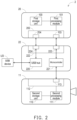
- FIG. 2 is a block schematic diagram of a projection system 2 of another embodiment of the disclosure.
- the projection system 2 includes an image control device 20, a projector 11, and a relay module 22.
- the projection system 2 of FIG. 2 is similar to the projection system 1 of FIG. 1 , so the same elements use the same symbols and are not repeated herein.
- the image control device 10 in FIG. 1 is replaced by the image control device 20 in FIG. 2
- a relay module 22 is also disposed between the image control device 20 and the projector 11, so that control signals may be transmitted between the image control device 20 and the projector 11 through the relay module 22.
- the first communication port 202 in the image control device 20 also includes a USB interface 204.
- the relay module 22 includes a USB hub 220, a microcontroller 221, and a third communication port 222.
- the third communication port 222 includes a UART interface 223 and a USB interface 224, which are respectively communicatively connected to the TTYS interface 103 and USB interface 204 of the first communication port 202.
- the third communication port 222 may be the aforementioned USB Type-C communication port.
- the first processing module 101 of the image control device 20 transmits the ASCII-encoded control signal from the TTYS interface 103 of the first communication port 202 to the UART interface 223 of the third communication port 222 of the relay module 22, and then provides it to the microcontroller 221 of the relay module 22.
- the microcontroller 221 may translate the control signal and then transmit it to the UART interface 113 of the second communication port 112 of the projector 11.
- the second processing module 111 of the projector 11 does not need to have the ASCII translation function, but directly causes the projector 11 to execute the corresponding function according to the control signal translated by the microcontroller 221 of the relay module 22.
- the USB hub 220 of the relay module 22 is connected to the USB device UD, and the USB hub 220 is communicatively connected to the USB interface 204 of the first communication port 202 of the image control device 20 through the USB interface 224 of the third communication port 222.
- the USB device UD may be an input device provided for user operation, such as a mouse or a keyboard. The user may provide input signals to the image control device 20 by controlling the USB device UD, thereby operating the application executed by the image control device 20.
- the first processing module 101 of the image control device 20 may generate the corresponding control signal, and provide it to the UART interface 113 of the second communication port 112 of the projector 11 through the TTYS interface 103 of the first communication port 202, the UART interface 223 of the third communication port 222 of the relay module 22, and the microcontroller 221, so that the projector 11 executes related functions.
- the USB device UD may also receive control signals from the image control device 20.
- the USB device UD may be a camera, and the image control device 20 outputs a control signal to the relay module 22 through the USB interface 204 of the first communication port 202, and transmits it to the USB device UD through the USB hub 220, so that the USB device UD executes an operation corresponding to the control signal (e.g., taking a photo). That is, the image control device 20 and the USB device UD may respectively perform bidirectional signal communication through the USB interface 204 of the first communication port 202 and the USB interface 224 of the third communication port 222.
- the relay module 22 added in the projection system 2 between the image control device 20 and the projector 11 may be, for example, a bridge device.
- the relay module 11 may also be configured to connect the TTYS interface 103 in the first communication port 202 to the UART interface 113 of the projector 11.
- the USB interface 204 is coupled to the USB hub 220 for bidirectional transmission of input signals or control signals.
- the USB interface 204 and the TTYS interface 103 in the first communication port 202 of the image control device 20 are integrated in the same communication port 202 (e.g., a USB Type-C communication port), but in other embodiments, the USB interface 204 and the TTYS interface 103 may also exist in different communication ports to perform bidirectional transmission of control signals and input signals, and the disclosure is not limited thereto. Similarly, the same is true for the third communication port 222 of the relay module 22, which is not repeated herein.
- the microcontroller 221 may be implemented using the same or similar elements as the first processing module 101 and/or the second processing module 111, which is not repeated herein.
- FIG. 3 is a block schematic diagram of a projection system 3 of another embodiment of the disclosure.
- the projection system 3 includes an image control device 20, a projector 11, and a relay module 32.
- the projection system 3 of FIG. 3 is similar to the projection system 2 of FIG. 2 , so the same elements use the same symbols and are not repeated herein.
- the relay module 22 in FIG. 2 is replaced by the relay module 32 in FIG. 3 , so that the UART interface 223 of the third communication port 222 is directly communicatively connected to the UART interface 113 of the second communication port 112.
- the UART interface 223 of the third communication port 222 provides the function of wiring connection or forwarding control signals between the TTYS interface 103 of the image control device 20 and the UART interface 113 of the projector 11, so that the control signal sent by the first processing module 101 of the image control device 20 may be provided from the TTYS interface 103 of the first communication port 102 to the UART interface 113 of the second communication port 112 through the communication connection of the third communication port 222 of the relay module 32.
- the relay module 32 also receives an input signal generated in response to the user operating the USB device UD, and the image control device 20 generates a corresponding control signal based on the input signal.
- the first processing module 101 of the image control device 20 may provide the control signal to the UART interface 223 of the third communication port 222 of the relay module 32 through the TTYS interface 103 of the first communication port 202, and further provide it to the UART interface 113 of the second communication port 112 of the projector 11.
- the UART interface 223 of the third communication port 222 of the relay module 32 is directly communicatively connected to the UART interface 113 of the second communication port 112 of the projector 11. Therefore, after the projector 11 receives the control signal, the ASCII-encoded control signal may be translated in the second processing module 111 of the projector 11, and then the projector 11 executes the corresponding operation.
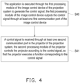
- FIG. 4 is a flowchart of a control method of an embodiment of the disclosure.
- the control method of FIG. 4 may be executed by any one of the projection systems 1 to 3 in FIG. 1 to FIG. 3 .
- the control method of FIG. 4 includes steps S40 and S41.
- the first processing module of the image control device of the projection system executes an application to generate a control signal.
- the first processing module of the image control device outputs the control signal through at least one first communication port of the image control device.
- the application executed by the image control device may provide a variety of functions for controlling the projector (e.g., system settings). The user may select the control item to be performed by operating the application, so that the first processing module of the image control device generates a control signal corresponding to the selected control item and provides the control signal to the projector.
- step S41 a control signal is received through at least one second communication port in the projector of the projection system.
- the second processing module of the projector controls the projector according to the control signal, so that the projector executes a function corresponding to the control signal.
- the projection system establishes a control signal transmission channel through specific interfaces between the first communication port and the second communication port.
- the differential signal docking pins in the USB Type-C communication port may be used as a TTYS interface to establish a control signal transmission channel with the UART interface in the second communication port of the projector. In this way, in the projection system, the items for the image control device to control the projector may be expanded.
- the projection system further includes a relay module coupled between the image control device and the projector.
- the relay module includes a third communication port, which is communicatively connected to the first communication port of the image control device.
- the third communication port may provide the control signal transmitted by the first communication port to the second communication port of the projector through wiring.
- FIG. 5A is a flowchart of a control method of another embodiment of the disclosure.
- the control method of FIG. 5A may be executed by any one of the projection systems 1 to 3 in FIG. 1 to FIG. 3 .
- the control method of FIG. 5A includes steps S50 to S54.
- Steps S50 and S51 may be executed by the image control device.
- the first processing module of the image control device may receive the input signal generated in response to the operation of the user by executing the application, thereby generating a corresponding control signal.
- the first processing module of the image control device may, for example, generate a control signal in a first encoding form (e.g., decimal) according to the input signal input by the user, by searching a first lookup table.
- the first lookup table may be stored in the first storage unit 100 of the image control device as shown in FIG. 1 to FIG. 3 .
- the image control device may use the differential signal docking pins in the first communication port as a TTYS interface to transmit the control signal.
- Steps S52 and S53 may be executed by the relay module.
- the relay module may receive the control signal and translate or forward it.
- the microcontroller in the relay module may, for example, translate the control signal from a first encoding form (e.g., decimal) to a second encoding form (e.g., hexadecimal).
- the relay module forwards the control signal, in the relay module, the UART interface of the third communication port may be connected to the UART interface of the second communication port of the projector through wiring. Therefore, in step S53, the relay module may transmit the processed control signal to the projector.
- Step S54 may be executed by the projector.
- the projector may receive the control signal through the UART interface on the second communication port and execute a corresponding function (e.g., system settings).
- the control method in FIG. 5A may omit steps S52 and S53. That is, in step S51, after the image control device sends the control signal, it is directly followed by step S54, where the projector receives the control signal.
- the second processing module in the projector may translate the control signal into a second encoding form (e.g., hexadecimal) by searching the second lookup table stored in the projector and then execute the corresponding function.
- the second lookup table may be stored in the second storage unit 110 of the projector as shown in FIG. 1 to FIG. 3 .
- FIG. 5B is a flowchart of a control method of another embodiment of the disclosure.
- the control method of FIG. 5B may be executed by any one of the projection systems 1 to 3 in FIG. 1 to FIG. 3 .
- the control method of FIG. 5B includes steps S55 to S59.
- step S55 may be executed by the projector.
- the projector may receive the first control signal (i.e., the input signal) generated in response to the operation of the user.
- the user may select the function to be performed (e.g., autofocus) by operating the remote controller of the projector, the buttons on the projector, or the on-screen display (OSD) displayed by the projector.
- the second processing module of the projector may send the first control signal corresponding to the command of the user for auto-focusing through the second communication port.
- Steps S56 and S57 may be executed by the relay module.
- the relay module may receive the first control signal and translate or forward it.
- the microcontroller in the relay module may, for example, translate the first control signal from a second encoding form (e.g., hexadecimal) to a first encoding form (e.g., decimal).
- the relay module forwards the first control signal, in the relay module, the UART interface of the second communication port of the projector may be communicatively connected to the TTYS interface of the first communication port of the image control device through wiring. Therefore, in step S57, the relay module may transmit the processed first control signal to the image control device.
- Steps S58 and S59 may be executed by the image control device.
- the image control device may receive the first control signal through the TTYS interface of the first communication port. Since in this embodiment, the operation commanded by the user is to perform auto-focusing, the first processing module of the image control device may accordingly initiate the application corresponding to the auto-focus or execute the corresponding function in the application. In order to perform auto-focusing, the first processing module may turn on the camera in the image control device (not shown in FIG. 1 to FIG. 3 ) or use the USB device UD external to the relay module to capture the projected image formed by the beam projected by the projector, and calculate the focal length adjustment range of the projector accordingly.
- step S59 the first processing module of the image control device may generate the corresponding second control signal according to the calculated focal length adjustment range.
- the control method of FIG. 5B may then execute the control method of FIG. 5A , that is, steps S51 to S54 may be executed after step S59.
- the projection system is a system setting that accepts user control to perform operation such as automatic focal length adjustment. Therefore, after the image control device calculates the focal length adjustment amount, the corresponding second control signal may be provided to the projector through steps S51 to S54, so that the projector receives and executes the second control signal to adjust the focal length by a corresponding amount to complete the auto-focus operation specified by the user.
- FIG. 6 is a block schematic diagram of a projection system 6 of another embodiment of the disclosure.
- the projection system 6 includes an image control device 60, a projector 61, and a relay module 62.
- the projection system 6 of FIG. 6 is similar to the projection system 1 of FIG. 1 , so the same elements use the same symbols and are not repeated herein.
- the interface 604 in the first communication port 602 of the image control device 60 is a USB interface
- the interface 614 in the second communication port 612 of the projector 61 may also be a USB interface.
- the relay module 62 is coupled between the image control device 60 and the projector 61.
- the image control device 60 includes a first storage unit 100
- the projector 61 includes a second storage unit 110
- the relay module 62 includes a third communication port 622, a USB bridge 625, a microcontroller 621, and a third storage unit 626.
- the relay module 62 is communicatively connected to the USB interface 604 of the first communication port 602 of the image control device 60 through the USB interface 624 of the third communication port 622.
- the USB bridge 625 is configured to receive control signals transmitted from the image control device 60 via the USB interface 604 of the first communication port 602 and the USB interface 624 of the third communication port 622, and transmits the control signal to the USB interface 614 of the second communication port 612 of the projector 61 in a forwarding manner.
- the control signal transmitted by the USB interface 604 of the communication port 602 and the USB interface 624 of the third communication port 622 is transmitted to the USB interface 614 of the second communication port 612 of the projector 61 in a forwarding manner.
- the microcontroller 621 is connected between the USB bridge 625 and the projector 61.
- the control signal is sequentially forwarded to the projector 61 through the USB interface 604 of the first communication port 602 of the image control device 60, the USB interface 624 of the third communication port 622 of the relay module 62, the USB bridge 625, the microcontroller 621, and the USB interface 614 of the second communication port 612 of the projector 61.
- the image control device 60 and the projector 61 may operate as master devices at the same time, and the relay module 62 is regarded as a medium to read and write commands to realize the transmission of control signals.
- the first storage unit 100 of the image control device 60 is configured to store the first data, and the projector 61 may access the first data through the USB bridge 625.
- the second storage unit 110 in the projector 61 is configured to store the second data, and the image control device 60 may access the second data through the USB bridge 625.
- the write command of the control signal (or the first data in the first storage unit 100) sent by the image control device 60 may carry the address information related to the third storage unit 626 in the relay module 62 to specify that the control signal is stored in the third storage unit 626 of the relay module 62.
- the relay module 62 may receive the write command through the USB interface 624 in the third communication port 622 and store the control signal in the storage unit 626.
- the second processing module 111 of the projector 61 may issue a read command, which may also carry address information related to the third storage unit 626 in the relay module 62 to read the control signal stored in the relay module 62.
- the relay module 62 may provide the control signal to the USB interface 614 of the second communication port 612 of the projector 61, so that the projector 61 receives the control signal (or the first data in the first storage unit 100) and performs the corresponding function according to the control signal.
- the reverse method of sending the control signal (or the second data in the second storage unit 110) from the projector 61 is also similar and is not repeated herein.
- the second communication port 612 of the projector 61 may also be provided with both a USB interface and a UART interface (e.g., combined with the embodiment of FIG. 1 ).
- the USB interface and UART interface of the second communication port may be integrated into the same communication port (e.g., the USB Type-C communication port) like the first communication port and the third communication port mentioned above, or may exist individually in different communication ports, and are not limited thereto.
- the third storage unit 626 may be implemented using the same or similar elements as the first storage unit 100 and/or the second storage unit 110, which is not repeated herein.
- FIG. 7 is a block schematic diagram of a projection system 7 of another embodiment of the disclosure.
- the projection system 7 of FIG. 7 is similar to the projection system 6 of FIG. 6 , so the same elements use the same symbols and are not repeated herein.
- the difference between the projection system 6 of FIG. 6 and the projection system 7 of FIG. 7 is that in the projection system 7 of FIG. 7 , there is no microcontroller provided on the path between the third communication port 622 of the relay module 72 and the second communication port 612 of the projector 61 for transmitting control signals.
- a microcontroller is provided on the path for transmitting control signals between the third communication port 622 and the second communication port 612 (as in the embodiment of FIG.
- the relay module may pre-process the control signal provided by the image control device 60 to reduce the calculation load of the second processing module 111 of the projector 61.
- the microcontroller may also be omitted from the path for transmitting control signals between the third communication port 622 and the second communication port 612.
- the relay module 72 only performs writing, accessing, and forwarding of the control signal, and does not perform signal pre-processing.
- the second processing module 111 in the projector 61 may perform necessary signal pre-processing operations after receiving the control signal.
- FIG. 8 is a flowchart of a control method of another embodiment of the disclosure.
- the control method of FIG. 8 may be executed by any one of the projection systems 6 and 7 in FIG. 6 and FIG. 7 .
- the control method of FIG. 8 includes steps S80 to S84.
- Steps S80 and S81 may be executed by the image control device.
- the first processing module of the image control device may receive the input signal generated in response to the operation of the user by executing the application, thereby generating a corresponding control signal.
- the image control device may issue a write command including the control signal through the USB interface in the first communication port to transmit the control signal to the relay module.
- Step S82 may be executed by the relay module.
- the relay module may receive the write command through the third communication port, and write the control signal into the third storage unit in the relay module according to the address information carried in the write command.
- Steps S83 and S84 may be executed by the projector.
- the second processing module of the projector may issue a read command to the relay module through the USB interface of the second communication port to read the control signal stored in the third storage unit of the relay module.
- the relay module may pre-process or forward the control signal to transmit the control signal to the projector.
- the second processing module of the projector may execute the corresponding function according to the read control signal.
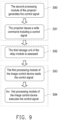
- FIG. 9 is a flowchart of a control method of another embodiment of the disclosure.
- the control method of FIG. 9 may be executed by any one of the projection systems 6 and 7 in FIG. 6 and FIG. 7 .
- the control method of FIG. 9 includes steps S90 to S94.
- Steps S90 and S91 may be executed by the projector.
- the second processing module of the projector may receive the input signal generated in response to the operation of the user, thereby generating a corresponding control signal.
- the projector may issue a write command including the control signal through the USB interface in the second communication port to transmit the control signal to the relay module.
- Step S92 may be executed by the relay module.
- the relay module may receive the write command and write the control signal into the third storage unit in the relay module according to the address information carried in the write command.
- Steps S93 and S94 may be executed by the image control device.
- the first processing module of the image control device may issue a read command to the relay module through the USB interface in the first communication port to read the control signal stored in the third storage unit of the relay module.
- the first processing module of the image control device may execute the corresponding function according to the read control signal.
- control method in FIG. 9 may also be applied to the aforementioned paragraphs, where the user controls the auto-focus by operating the projector.
- the projection system may command the image control device from the projector to initiate the application corresponding to the auto-focus or to execute the corresponding function in the application by executing steps S90 to S94. Therefore, after executing the relevant operations and calculating the focal length adjustment amount of the projector, the image control device may continue to execute the control method of FIG. 8 to provide the control signal including the focal length adjustment amount to the projector through steps S80 to S84, so that the projector receives and executes the control signal to adjust the focal length by a corresponding amount to complete the auto-focus operation specified by the user.
- the projection system and control method of the disclosure may transmit control signals through at least one of the TTYS interface or USB interface in the image control device, thereby realizing the function of controlling the projector (e.g., system settings) in a relatively simple way.
- the term “the disclosure”, “the present disclosure” or the like does not necessarily limit the claim scope to a specific embodiment, and the reference to particularly preferred exemplary embodiments of the disclosure does not imply a limitation on the disclosure, and no such limitation is to be inferred.
- the disclosure is limited only by the scope of the appended claims. Moreover, these claims may refer to use “first”, “second”, etc. following with noun or element. Such terms should be understood as a nomenclature and should not be construed as giving the limitation on the number of the elements modified by such nomenclature unless specific number has been given.
- the abstract of the disclosure is provided to comply with the rules requiring an abstract, which will allow a searcher to quickly ascertain the subject matter of the technical disclosure of any patent issued from this disclosure.
Landscapes
- Engineering & Computer Science (AREA)
- Theoretical Computer Science (AREA)
- General Engineering & Computer Science (AREA)
- Physics & Mathematics (AREA)
- General Physics & Mathematics (AREA)
- Signal Processing (AREA)
- Automation & Control Theory (AREA)
- Computer Hardware Design (AREA)
- Computer Networks & Wireless Communication (AREA)
- Multimedia (AREA)
- Computing Systems (AREA)
- Human Computer Interaction (AREA)
- Projection Apparatus (AREA)
- Controls And Circuits For Display Device (AREA)
- Transforming Electric Information Into Light Information (AREA)
Abstract
Description
- This application claims the priority of
US provisional application serial no. 63/595,759, filed on November 3, 2023 China application serial no. 202410062975.0, filed on January 16, 2024 - The disclosure relates to a system and a method, and in particular relates to a projection system and a control method.
- In the commonly used Internet TV environment today, it generally only has basic playback operation functions and does not have the ability to adjust system settings for externally connected display monitors or projectors. On the other hand, when developing applications with system setting functions in these Internet TV environments, it may require overcoming stringent system security permissions, or bearing the high cost of application maintenance. Therefore, in the current Internet TV environment, the development of an application that integrates the system settings of a display or projector requires substantial resources in terms of manpower and financial investment.
- The information disclosed in this Background section is only for enhancement of understanding of the background of the described technology and therefore it may contain information that does not form the prior art that is already known to a person of ordinary skill in the art. Further, the information disclosed in the Background section does not mean that one or more problems to be resolved by one or more embodiments of the disclosure was acknowledged by a person of ordinary skill in the art.
- The object of the present invention is solved by the features of the independent claims. Preferred embodiments are given in the dependent claims.
- A projection system according to an embodiment of the disclosure includes an image control device and a projector. The image control device includes a first processing module, an application, and a first communication port. The first processing module is configured to execute the application and generate the control signal through the application. The first processing module outputs the control signal through the first communication port. The projector includes a second processing module and a second communication port. The projector is communicatively connected to the first communication port of the image control device through the second communication port. The second processing module receives the control signal through the second communication port and controls the projector according to the control signal, so that the projector executes a function corresponding to the control signal. The first communication port includes at least one of a teletype serial (TTYS) interface and a universal serial bus (USB) interface.
- A control method according to an embodiment of the disclosure is adapted to control a projection system. The control method includes the following operation. The application is executed through the first processing module of the image control device of the projection system to generate the control signal, the first processing module of the image control device outputs the control signal through a first communication port of the image control device. A control signal is received through a second communication port in the projector of the projection system, the second processing module of the projector controls the projector according to the control signal, so that the projector executes a function corresponding to the control signal. The first communication port includes at least one of a teletype serial (TTYS) interface and a universal serial bus (USB) interface.
- In one or more embodiments, the at least one first communication port may be a universal serial bus Type-C interface (USB Type-C) communication port or a serial advanced technology attachment (SATA) communication port.
- In one or more embodiments, when the at least one first communication port is a USB Type-C communication port, the TTYS interface of the at least one first communication port may be located at differential signal docking pins in the USB Type-C communication port.
- In one or more embodiments, the USB interface of the at least one first communication port may be located at USB 2.0 interface pins in the USB Type-C communication port.
- In one or more embodiments, the at least one second communication port may comprise at least one of a universal asynchronous receiver/transmitter (UART) interface and a universal serial bus (USB) interface.
- In one or more embodiments, when the control signal is output from the image control device through the TTYS interface of the at least one first communication port, the projector may receive the control signal through the UART interface of the at least one second communication port.
- In one or more embodiments, when the control signal is output from the image control device through the USB interface of the at least one first communication port, the projector may receive the control signal through the USB interface of the at least one second communication port.
- In one or more embodiments, the projection system may further comprise a relay module.
- In one or more embodiments, the relay module may comprise at least one third communication port.
- In one or more embodiments, the relay module may be communicatively connected to the at least one first communication port of the image control device through a UART interface of the at least one third communication port.
- In one or more embodiments, the first processing module of the image control device may be configured to transmit the control signal to the relay module through the TTYS interface of the at least one first communication port and the UART interface of the at least one third communication port.
- In one or more embodiments, the relay module may further comprise a microcontroller configured to translate the control signal.
- In one or more embodiments, the control signal transmitted to the projector through the UART interface of the at least one second communication port after the control signal may be translated by the microcontroller.
- In one or more embodiments, the relay module may further comprise a USB hub configured to connect at least one USB device.
- In one or more embodiments, the USB hub may be communicatively connected to the at least one first communication port of the image control device through a USB interface of the at least one third communication port.
- In one or more embodiments, the image control device may output the control signal to the relay module through the USB interface of the at least one first communication port, and may transmit the control signal to the USB device through the USB hub, so that the at least one USB device executes an operation corresponding to the control signal.
- In one or more embodiments, the projection system may further comprise a relay module.
- In one or more embodiments, the relay module may comprise at least one third communication port and a USB bridge.
- In one or more embodiments, the at least one second communication port may comprise a USB interface.
- In one or more embodiments, the relay module may be communicatively connected to the at least one first communication port of the image control device through a USB interface of the at least one third communication port.
- In one or more embodiments, the USB bridge may be configured to receive the control signal transmitted from the image control device through the USB interface of the at least one first communication port and the USB interface of the at least one third communication port, and to transmit the control signal to the USB interface of the at least one second communication port of the projector in a forwarding manner.
- In one or more embodiments, the image control device may further comprise a first storage unit configured to store a first data.
- In one or more embodiments, the projector may access the first data through the USB bridge.
- In one or more embodiments, the projector may further comprise a second storage unit configured to store a second data.
- In one or more embodiments, the image control device may access the second data through the USB bridge.
- In one or more embodiments, the relay module may further comprise a microcontroller.
- In one or more embodiments, the microcontroller may be connected between the USB bridge and the projector.
- In one or more embodiments, the control signal may be sequentially forwarded to the projector through the USB interface of the at least one first communication port, the USB interface of the at least one third communication port, the USB bridge, the microcontroller, and the USB interface of the at least one second communication port.
- In one or more embodiments, the at least one first communication port may be a universal serial bus type C interface (USB Type-C) communication port or a serial advanced technology attachment (SATA) communication port.
- In one or more embodiments, when the at least one first communication port is a USB Type-C communication port, the TTYS interface of the at least one first communication port may be located at differential signal docking pins in the USB Type-C communication port, the USB interface of the at least one first communication port may be located at USB 2.0 interface pins in the USB Type-C communication port.
- In one or more embodiments, the at least one second communication port may comprise at least one of a universal asynchronous receiver/transmitter (UART) interface and a universal serial bus (USB) interface.
- In one or more embodiments, when the control signal is output from the image control device through the TTYS interface of the at least one first communication port, the projector may receive the control signal through the UART interface of the at least one second communication port.
- In one or more embodiments, when the control signal is output from the image control device through the USB interface of the at least one first communication port, the projector may receive the control signal through the USB interface of the at least one second communication port.
- In one or more embodiments, the projector system may comprise a relay module.
- In one or more embodiments, the relay module may comprise at least one third communication port.
- In one or more embodiments, the control signal may be transmitted to the relay module by the first processing module of the image control device through the TTYS interface of the at least one first communication port and a UART interface of the at least one third communication port.
- In one or more embodiments, a microcontroller of the relay module may translate the control signal, and may transmit the control signal to the projector through the UART interface of the at least one second communication port.
- In one or more embodiments, the relay module may further comprise a USB hub configured to connect at least one USB device.
- In one or more embodiments, the control method may further comprise outputting the control signal through the USB interface of the at least one first communication port and transmitting the control signal to the at least one USB device in the relay module through a USB interface of the at least one third communication port and the USB hub, so that the at least one USB device executes an operation corresponding to the control signal.
- In one or more embodiments, projection system may further comprise a relay module.
- In one or more embodiments, the relay module may comprise at least one third communication port and a USB bridge.
- In one or more embodiments, the at least one second communication port may comprise a USB interface.
- In one or more embodiments, the control method may further comprise receiving the control signal transmitted from the image control device through the USB interface of the at least one first communication port and a USB interface of the at least one third communication port through the USB bridge of the relay module, and transmitting the control signal to the projector through the USB interface of the at least one second communication port in a forwarding manner.
- In one or more embodiments, the projector may access a first data in a first storage unit of the image control device through the USB bridge.
- In one or more embodiments, the image control device may access a second data in a second storage unit of the projector through the USB bridge.
- In one or more embodiments, the relay module may further comprise a microcontroller.
- In one or more embodiments, the control signal may be sequentially forwarded to the projector through the USB interface of the at least one first communication port, the USB interface of the at least one third communication port, the USB bridge, the microcontroller, and the USB interface of the at least one second communication port.
- Other objectives, features and advantages of the present disclosure will be further understood from the further technological features disclosed by the embodiments of the present disclosure wherein there are shown and described preferred embodiments of this disclosure, simply by way of illustration of modes best suited to carry out the disclosure.
-
-
FIG. 1 is a block schematic diagram of a projection system of an embodiment of the disclosure. -
FIG. 2 is a block schematic diagram of a projection system of another embodiment of the disclosure. -
FIG. 3 is a block schematic diagram of a projection system of another embodiment of the disclosure. -
FIG. 4 is a flowchart of a control method of an embodiment of the disclosure. -
FIG. 5A is a flowchart of a control method of another embodiment of the disclosure. -
FIG. 5B is a flowchart of a control method of another embodiment of the disclosure. -
FIG. 6 is a block schematic diagram of a projection system of another embodiment of the disclosure. -
FIG. 7 is a block schematic diagram of a projection system of another embodiment of the disclosure. -
FIG. 8 is a flowchart of a control method of another embodiment of the disclosure. -
FIG. 9 is a flowchart of a control method of another embodiment of the disclosure. - It is to be understood that other embodiment may be utilized and structural changes may be made without departing from the scope of the disclosure. Also, it is to be understood that the phraseology and terminology used herein are for the purpose of description and should not be regarded as limiting. The use of "including," "comprising," or "having" and variations thereof herein is meant to encompass the items listed thereafter and equivalents thereof as well as additional items. Unless limited otherwise, the terms "connected," "coupled," and "mounted," and variations thereof herein are used broadly and encompass direct and indirect connections, couplings, and mountings.
- The above and other technical contents, features and effects of the disclosure will be clear from the below detailed description of an embodiment of the disclosure with reference to accompanying drawings.
- A projection system and a control method, which may provide the function of controlling a projector in an existing Internet TV environment, are provided in the disclosure.
- The other objectives and advantages of the disclosure may be further understood from the descriptive features disclosed in the disclosure.
-
FIG. 1 is a block schematic diagram of aprojection system 1 of an embodiment of the disclosure. Theprojection system 1 includes animage control device 10 and aprojector 11. Theimage control device 10 includes afirst processing module 101, an application (App), and at least onefirst communication port 102. Thefirst processing module 101 includes at least one processor configured to execute the application and generate a control signal through the application. Thefirst processing module 101 outputs the control signal through at least onefirst communication port 102. - Specifically, the
first communication port 102 in theimage control device 10 may include aninterface 103, which may be at least one of a teletype serial (TTYS) interface and a universal serial bus (USB) interface. Theinterface 103 of thefirst communication port 102 is used to communicatively connect to theprojector 11. In addition, theprojector 11 includes asecond processing module 111, at least asecond communication port 112, and asecond storage unit 110. Theprojector 11 is communicatively connected to thefirst communication port 102 of theimage control device 10 through thesecond communication port 112. Thesecond processing module 111 receives the control signal through thesecond communication port 112 and controls theprojector 11 according to the control signal, so that theprojector 11 performs a function corresponding to the control signal. Thesecond communication port 112 in theprojector 11 may include aninterface 113, which may be at least one of a universal asynchronous receiver/transmitter (UART) interface and a universal serial bus (USB) interface. Theinterface 113 of thesecond communication port 112 is used to communicatively connect to theinterface 103 of thefirst communication port 102 of theimage control device 10. In this way, theimage control device 10 and theprojector 11 may transmit control signals through the mutually communicativelyconnected interfaces image control device 10 controlling (e.g., system settings) theprojector 11. - In this embodiment, the
first communication port 102 of theimage control device 10 has aTTYS interface 103, and thesecond communication port 112 of theprojector 11 has aUART interface 113. Theimage control device 10 uses theTTYS interface 103 of thefirst communication port 102 and theUART interface 113 of thesecond communication port 112 to transmit the control signal from theimage control device 10 to theprojector 11 to control the projector 11 (e.g., the system settings of the projector). In other embodiments, thefirst communication port 102 of theimage control device 10 has a USB interface, and thesecond communication port 112 of theprojector 11 also has a USB interface. When the control signal is output from theimage control device 10 through the USB interface of thefirst communication port 102, theprojector 11 receives the control signal through the USB interface of thesecond communication port 112, but the disclosure is not limited thereto. - Specifically, the
image control device 10 further includes afirst storage unit 100. Thefirst storage unit 100 stores applications, which are, for example, applications compatible with Google TV, Android TV, Apple TV, or other similar Internet TV environments. Thefirst processing module 101 may execute an application by accessing thefirst storage unit 100 to control theprojector 11 to play the corresponding projection image. In addition, the user may also execute the application by operating theimage control device 10 to control the projector 11 (e.g., system settings). For example, when the user uses theprojection system 1 to play a video and intends to adjust the brightness of the projected image from theprojector 11, the user may initiate and execute the application accessed by thefirst processing module 101 by operating theimage control device 10. The application provides a menu of a variety of system control, and the user may select the option to adjust the brightness of the projected image through the menu of the application. In this way, in response to the operation of the user, thefirst processing module 101 of theimage control device 10 may generate a control signal and perform ASCII (American standard code for information interchange) encoding on the control signal, and output the encoding through theTTYS interface 103 in thefirst communication port 102 to theUART interface 113 in thesecond communication port 112 of theprojector 11. Thesecond processing module 111 of theprojector 11 includes at least one processor, such as a system on chip (SoC). In this embodiment, ASCII decoding may be programmed in thesecond processing module 111. After theUART interface 113 of thesecond communication port 112 of theprojector 11 receives the ASCII-encoded control signal, thesecond processing module 111 translates the control signal, and changes the brightness of the projected image of theprojector 11 according to the translated control signal. - In this embodiment, the
first communication port 102 is, for example, a USB Type-C communication port. Specifically, it may be a full-featured (DisplayPort Alt Mode) USB Type-C communication port. TheTTYS interface 103 used to transmit control signals may be located at the differential signal docking pins (Tx, Rx) in the USB Type-C communication port. However, in other embodiments, if the USB interface is used as theinterface 103 for transmitting control signals, the USB interface is located at the USB 2.0 interface pins in the USB Type-C communication port (i.e., the first communication port). In addition, thefirst communication port 102 may also be a serial advanced technology attachment (SATA) communication port, a bus communication port, or other communication ports that may be configured to transmit control signals. - In this embodiment, the
first communication port 102 and thesecond communication port 112 may be communication ports with the same transmission standard. For example, thefirst communication port 102 and thesecond communication port 112 may both be USB Type-C communication ports, and theinterfaces image control device 10 and theprojector 11 may use the differential signal docking pins in the male to female connected USB Type-C communication port as the TTYS interface and the UART interface to realize the transmission of control signals. It should be noted that in this embodiment, theimage control device 10 and theprojector 11 are directly communicatively connected through thefirst communication port 102 and thesecond communication port 112 for signal transmission. However, in other embodiments, theimage control device 10 and theprojector 11 may also transmit signals through an indirect communication connection through thefirst communication port 102 and thesecond communication port 112, and the disclosure is not limited thereto. - In one embodiment, the
first storage unit 100 and/or thesecond storage unit 110 may be, for example, any type of fixed or movable random access memory (RAM), read-only memory (ROM), flash memory, hard disk drive (HDD), solid state drive (SSD), or similar elements, or a combination thereof. - In one embodiment, the
first processing module 101 and/or thesecond processing module 111 may be, for example, a central processing unit (CPU), or other programmable general-purpose or special-purpose micro control unit (MCU), microprocessor, digital signal processor (DSP), programmable controller, application specific integrated circuit (ASIC), graphics processing unit (GPU), arithmetic logic unit (ALU), complex programmable logic device (CPLD), field programmable gate array (FPGA), any other type of integrated circuit, state machine, processor based on advanced RISC machine (ARM), or other similar elements, or a combination of the elements thereof. Alternatively, thefirst processing module 101 and/or thesecond processing module 111 may be hardware circuits implemented through a hardware description language (HDL) or any other digital circuit design method that is well known to those skilled in the art. -
FIG. 2 is a block schematic diagram of aprojection system 2 of another embodiment of the disclosure. Theprojection system 2 includes animage control device 20, aprojector 11, and arelay module 22. Theprojection system 2 ofFIG. 2 is similar to theprojection system 1 ofFIG. 1 , so the same elements use the same symbols and are not repeated herein. Specifically, theimage control device 10 inFIG. 1 is replaced by theimage control device 20 inFIG. 2 , and arelay module 22 is also disposed between theimage control device 20 and theprojector 11, so that control signals may be transmitted between theimage control device 20 and theprojector 11 through therelay module 22. - In addition to the
TTYS interface 103, thefirst communication port 202 in theimage control device 20 also includes aUSB interface 204. On the other hand, therelay module 22 includes aUSB hub 220, amicrocontroller 221, and athird communication port 222. Thethird communication port 222 includes aUART interface 223 and aUSB interface 224, which are respectively communicatively connected to theTTYS interface 103 andUSB interface 204 of thefirst communication port 202. Specifically, thethird communication port 222 may be the aforementioned USB Type-C communication port. Thefirst processing module 101 of theimage control device 20 transmits the ASCII-encoded control signal from theTTYS interface 103 of thefirst communication port 202 to theUART interface 223 of thethird communication port 222 of therelay module 22, and then provides it to themicrocontroller 221 of therelay module 22. Themicrocontroller 221 may translate the control signal and then transmit it to theUART interface 113 of thesecond communication port 112 of theprojector 11. At this time, thesecond processing module 111 of theprojector 11 does not need to have the ASCII translation function, but directly causes theprojector 11 to execute the corresponding function according to the control signal translated by themicrocontroller 221 of therelay module 22. - On the other hand, the
USB hub 220 of therelay module 22 is connected to the USB device UD, and theUSB hub 220 is communicatively connected to theUSB interface 204 of thefirst communication port 202 of theimage control device 20 through theUSB interface 224 of thethird communication port 222. In one embodiment, the USB device UD may be an input device provided for user operation, such as a mouse or a keyboard. The user may provide input signals to theimage control device 20 by controlling the USB device UD, thereby operating the application executed by theimage control device 20. After receiving the input signal for operating the application, thefirst processing module 101 of theimage control device 20 may generate the corresponding control signal, and provide it to theUART interface 113 of thesecond communication port 112 of theprojector 11 through theTTYS interface 103 of thefirst communication port 202, theUART interface 223 of thethird communication port 222 of therelay module 22, and themicrocontroller 221, so that theprojector 11 executes related functions. In other embodiments, the USB device UD may also receive control signals from theimage control device 20. For example, the USB device UD may be a camera, and theimage control device 20 outputs a control signal to therelay module 22 through theUSB interface 204 of thefirst communication port 202, and transmits it to the USB device UD through theUSB hub 220, so that the USB device UD executes an operation corresponding to the control signal (e.g., taking a photo). That is, theimage control device 20 and the USB device UD may respectively perform bidirectional signal communication through theUSB interface 204 of thefirst communication port 202 and theUSB interface 224 of thethird communication port 222. - Specifically, the
relay module 22 added in theprojection system 2 between theimage control device 20 and theprojector 11 may be, for example, a bridge device. In addition to being configured to couple theTTYS interface 103 in thefirst communication port 202 to theUART interface 113 of theprojector 11, therelay module 11 may also be configured to connect theTTYS interface 103 in thefirst communication port 202 to theUART interface 113 of theprojector 11. TheUSB interface 204 is coupled to theUSB hub 220 for bidirectional transmission of input signals or control signals. - In addition, in this embodiment, the
USB interface 204 and theTTYS interface 103 in thefirst communication port 202 of theimage control device 20 are integrated in the same communication port 202 (e.g., a USB Type-C communication port), but in other embodiments, theUSB interface 204 and theTTYS interface 103 may also exist in different communication ports to perform bidirectional transmission of control signals and input signals, and the disclosure is not limited thereto. Similarly, the same is true for thethird communication port 222 of therelay module 22, which is not repeated herein. - In one embodiment, the
microcontroller 221 may be implemented using the same or similar elements as thefirst processing module 101 and/or thesecond processing module 111, which is not repeated herein. -
FIG. 3 is a block schematic diagram of aprojection system 3 of another embodiment of the disclosure. Theprojection system 3 includes animage control device 20, aprojector 11, and arelay module 32. Theprojection system 3 ofFIG. 3 is similar to theprojection system 2 ofFIG. 2 , so the same elements use the same symbols and are not repeated herein. Specifically, therelay module 22 inFIG. 2 is replaced by therelay module 32 inFIG. 3 , so that theUART interface 223 of thethird communication port 222 is directly communicatively connected to theUART interface 113 of thesecond communication port 112. In other words, in this embodiment, theUART interface 223 of thethird communication port 222 provides the function of wiring connection or forwarding control signals between theTTYS interface 103 of theimage control device 20 and theUART interface 113 of theprojector 11, so that the control signal sent by thefirst processing module 101 of theimage control device 20 may be provided from theTTYS interface 103 of thefirst communication port 102 to theUART interface 113 of thesecond communication port 112 through the communication connection of thethird communication port 222 of therelay module 32. - In this embodiment, the
relay module 32 also receives an input signal generated in response to the user operating the USB device UD, and theimage control device 20 generates a corresponding control signal based on the input signal. Thefirst processing module 101 of theimage control device 20 may provide the control signal to theUART interface 223 of thethird communication port 222 of therelay module 32 through theTTYS interface 103 of thefirst communication port 202, and further provide it to theUART interface 113 of thesecond communication port 112 of theprojector 11. - In this embodiment, the
UART interface 223 of thethird communication port 222 of therelay module 32 is directly communicatively connected to theUART interface 113 of thesecond communication port 112 of theprojector 11. Therefore, after theprojector 11 receives the control signal, the ASCII-encoded control signal may be translated in thesecond processing module 111 of theprojector 11, and then theprojector 11 executes the corresponding operation. -
FIG. 4 is a flowchart of a control method of an embodiment of the disclosure. The control method ofFIG. 4 may be executed by any one of theprojection systems 1 to 3 inFIG. 1 to FIG. 3 . The control method ofFIG. 4 includes steps S40 and S41. - In step S40, the first processing module of the image control device of the projection system executes an application to generate a control signal. The first processing module of the image control device outputs the control signal through at least one first communication port of the image control device. Specifically, the application executed by the image control device may provide a variety of functions for controlling the projector (e.g., system settings). The user may select the control item to be performed by operating the application, so that the first processing module of the image control device generates a control signal corresponding to the selected control item and provides the control signal to the projector.
- In step S41, a control signal is received through at least one second communication port in the projector of the projection system. The second processing module of the projector controls the projector according to the control signal, so that the projector executes a function corresponding to the control signal.
- In one embodiment, the projection system establishes a control signal transmission channel through specific interfaces between the first communication port and the second communication port. For example, when the first communication port of the image control device is a USB Type-C communication port, the differential signal docking pins in the USB Type-C communication port may be used as a TTYS interface to establish a control signal transmission channel with the UART interface in the second communication port of the projector. In this way, in the projection system, the items for the image control device to control the projector may be expanded.
- In some embodiments, the projection system further includes a relay module coupled between the image control device and the projector. The relay module includes a third communication port, which is communicatively connected to the first communication port of the image control device. The third communication port may provide the control signal transmitted by the first communication port to the second communication port of the projector through wiring.
-
FIG. 5A is a flowchart of a control method of another embodiment of the disclosure. The control method ofFIG. 5A may be executed by any one of theprojection systems 1 to 3 inFIG. 1 to FIG. 3 . The control method ofFIG. 5A includes steps S50 to S54. - Steps S50 and S51 may be executed by the image control device. In step S50, the first processing module of the image control device may receive the input signal generated in response to the operation of the user by executing the application, thereby generating a corresponding control signal. In some embodiments, the first processing module of the image control device may, for example, generate a control signal in a first encoding form (e.g., decimal) according to the input signal input by the user, by searching a first lookup table. The first lookup table may be stored in the
first storage unit 100 of the image control device as shown inFIG. 1 to FIG. 3 . Next, in step S51, the image control device may use the differential signal docking pins in the first communication port as a TTYS interface to transmit the control signal. - Steps S52 and S53 may be executed by the relay module. In step S52, the relay module may receive the control signal and translate or forward it. In some embodiments, when the relay module translates the control signal, the microcontroller in the relay module may, for example, translate the control signal from a first encoding form (e.g., decimal) to a second encoding form (e.g., hexadecimal). In some embodiments, when the relay module forwards the control signal, in the relay module, the UART interface of the third communication port may be connected to the UART interface of the second communication port of the projector through wiring. Therefore, in step S53, the relay module may transmit the processed control signal to the projector.
- Step S54 may be executed by the projector. In step S54, the projector may receive the control signal through the UART interface on the second communication port and execute a corresponding function (e.g., system settings).
- In some embodiments, when the projection system does not include a relay module, the control method in
FIG. 5A may omit steps S52 and S53. That is, in step S51, after the image control device sends the control signal, it is directly followed by step S54, where the projector receives the control signal. In one embodiment, when the projector receives the control signal directly from the image control device, or the control signal received by the projector is only forwarded through the relay module without being translated, the second processing module in the projector may translate the control signal into a second encoding form (e.g., hexadecimal) by searching the second lookup table stored in the projector and then execute the corresponding function. The second lookup table may be stored in thesecond storage unit 110 of the projector as shown inFIG. 1 to FIG. 3 . -
FIG. 5B is a flowchart of a control method of another embodiment of the disclosure. The control method ofFIG. 5B may be executed by any one of theprojection systems 1 to 3 inFIG. 1 to FIG. 3 . The control method ofFIG. 5B includes steps S55 to S59. - In the projection system, in addition to the transmission of control signals initiated by the image control device, the transmission of control signals may also be initiated by the projector to realize bidirectional communication between the image control device and the projector. Specifically, step S55 may be executed by the projector. In step S55, the projector may receive the first control signal (i.e., the input signal) generated in response to the operation of the user. For example, the user may select the function to be performed (e.g., autofocus) by operating the remote controller of the projector, the buttons on the projector, or the on-screen display (OSD) displayed by the projector. In this way, the second processing module of the projector may send the first control signal corresponding to the command of the user for auto-focusing through the second communication port.
- Steps S56 and S57 may be executed by the relay module. In step S56, the relay module may receive the first control signal and translate or forward it. In one embodiment, when the relay module translates the first control signal, the microcontroller in the relay module may, for example, translate the first control signal from a second encoding form (e.g., hexadecimal) to a first encoding form (e.g., decimal). In one embodiment, when the relay module forwards the first control signal, in the relay module, the UART interface of the second communication port of the projector may be communicatively connected to the TTYS interface of the first communication port of the image control device through wiring. Therefore, in step S57, the relay module may transmit the processed first control signal to the image control device.
- Steps S58 and S59 may be executed by the image control device. In step S58, the image control device may receive the first control signal through the TTYS interface of the first communication port. Since in this embodiment, the operation commanded by the user is to perform auto-focusing, the first processing module of the image control device may accordingly initiate the application corresponding to the auto-focus or execute the corresponding function in the application. In order to perform auto-focusing, the first processing module may turn on the camera in the image control device (not shown in
FIG. 1 to FIG. 3 ) or use the USB device UD external to the relay module to capture the projected image formed by the beam projected by the projector, and calculate the focal length adjustment range of the projector accordingly. In this way, in step S59, the first processing module of the image control device may generate the corresponding second control signal according to the calculated focal length adjustment range. In one embodiment, the control method ofFIG. 5B may then execute the control method ofFIG. 5A , that is, steps S51 to S54 may be executed after step S59. Specifically, in this embodiment, the projection system is a system setting that accepts user control to perform operation such as automatic focal length adjustment. Therefore, after the image control device calculates the focal length adjustment amount, the corresponding second control signal may be provided to the projector through steps S51 to S54, so that the projector receives and executes the second control signal to adjust the focal length by a corresponding amount to complete the auto-focus operation specified by the user. -
FIG. 6 is a block schematic diagram of aprojection system 6 of another embodiment of the disclosure. Theprojection system 6 includes animage control device 60, aprojector 61, and arelay module 62. Theprojection system 6 ofFIG. 6 is similar to theprojection system 1 ofFIG. 1 , so the same elements use the same symbols and are not repeated herein. In this embodiment, theinterface 604 in thefirst communication port 602 of theimage control device 60 is a USB interface, and theinterface 614 in thesecond communication port 612 of theprojector 61 may also be a USB interface. In addition, therelay module 62 is coupled between theimage control device 60 and theprojector 61. Specifically, theimage control device 60 includes afirst storage unit 100, theprojector 61 includes asecond storage unit 110, and therelay module 62 includes athird communication port 622, aUSB bridge 625, amicrocontroller 621, and athird storage unit 626. Therelay module 62 is communicatively connected to theUSB interface 604 of thefirst communication port 602 of theimage control device 60 through theUSB interface 624 of thethird communication port 622. TheUSB bridge 625 is configured to receive control signals transmitted from theimage control device 60 via theUSB interface 604 of thefirst communication port 602 and theUSB interface 624 of thethird communication port 622, and transmits the control signal to theUSB interface 614 of thesecond communication port 612 of theprojector 61 in a forwarding manner. The control signal transmitted by theUSB interface 604 of thecommunication port 602 and theUSB interface 624 of thethird communication port 622 is transmitted to theUSB interface 614 of thesecond communication port 612 of theprojector 61 in a forwarding manner. In addition, themicrocontroller 621 is connected between theUSB bridge 625 and theprojector 61. The control signal is sequentially forwarded to theprojector 61 through theUSB interface 604 of thefirst communication port 602 of theimage control device 60, theUSB interface 624 of thethird communication port 622 of therelay module 62, theUSB bridge 625, themicrocontroller 621, and theUSB interface 614 of thesecond communication port 612 of theprojector 61. - In terms of operation, the
image control device 60 and theprojector 61 may operate as master devices at the same time, and therelay module 62 is regarded as a medium to read and write commands to realize the transmission of control signals. For example, thefirst storage unit 100 of theimage control device 60 is configured to store the first data, and theprojector 61 may access the first data through theUSB bridge 625. Alternatively, thesecond storage unit 110 in theprojector 61 is configured to store the second data, and theimage control device 60 may access the second data through theUSB bridge 625. In one embodiment, the write command of the control signal (or the first data in the first storage unit 100) sent by theimage control device 60 may carry the address information related to thethird storage unit 626 in therelay module 62 to specify that the control signal is stored in thethird storage unit 626 of therelay module 62. Therelay module 62 may receive the write command through theUSB interface 624 in thethird communication port 622 and store the control signal in thestorage unit 626. On the other hand, thesecond processing module 111 of theprojector 61 may issue a read command, which may also carry address information related to thethird storage unit 626 in therelay module 62 to read the control signal stored in therelay module 62. Therelay module 62 may provide the control signal to theUSB interface 614 of thesecond communication port 612 of theprojector 61, so that theprojector 61 receives the control signal (or the first data in the first storage unit 100) and performs the corresponding function according to the control signal. The reverse method of sending the control signal (or the second data in the second storage unit 110) from theprojector 61 is also similar and is not repeated herein. - In addition, in this embodiment, although the
second communication port 612 of theprojector 61 only has one USB interface, in other embodiments, the second communication port may also be provided with both a USB interface and a UART interface (e.g., combined with the embodiment ofFIG. 1 ). The USB interface and UART interface of the second communication port may be integrated into the same communication port (e.g., the USB Type-C communication port) like the first communication port and the third communication port mentioned above, or may exist individually in different communication ports, and are not limited thereto. - In one embodiment, the
third storage unit 626 may be implemented using the same or similar elements as thefirst storage unit 100 and/or thesecond storage unit 110, which is not repeated herein. -
FIG. 7 is a block schematic diagram of aprojection system 7 of another embodiment of the disclosure. Theprojection system 7 ofFIG. 7 is similar to theprojection system 6 ofFIG. 6 , so the same elements use the same symbols and are not repeated herein. The difference between theprojection system 6 ofFIG. 6 and theprojection system 7 ofFIG. 7 is that in theprojection system 7 ofFIG. 7 , there is no microcontroller provided on the path between thethird communication port 622 of therelay module 72 and thesecond communication port 612 of theprojector 61 for transmitting control signals. Specifically, when a microcontroller is provided on the path for transmitting control signals between thethird communication port 622 and the second communication port 612 (as in the embodiment ofFIG. 6 ), the relay module may pre-process the control signal provided by theimage control device 60 to reduce the calculation load of thesecond processing module 111 of theprojector 61. However, in this embodiment, the microcontroller may also be omitted from the path for transmitting control signals between thethird communication port 622 and thesecond communication port 612. In this way, therelay module 72 only performs writing, accessing, and forwarding of the control signal, and does not perform signal pre-processing. Correspondingly, thesecond processing module 111 in theprojector 61 may perform necessary signal pre-processing operations after receiving the control signal. -
FIG. 8 is a flowchart of a control method of another embodiment of the disclosure. The control method ofFIG. 8 may be executed by any one of theprojection systems FIG. 6 andFIG. 7 . The control method ofFIG. 8 includes steps S80 to S84. - Steps S80 and S81 may be executed by the image control device. In step S80, the first processing module of the image control device may receive the input signal generated in response to the operation of the user by executing the application, thereby generating a corresponding control signal. Next, in step S81, the image control device may issue a write command including the control signal through the USB interface in the first communication port to transmit the control signal to the relay module.
- Step S82 may be executed by the relay module. In step S82, the relay module may receive the write command through the third communication port, and write the control signal into the third storage unit in the relay module according to the address information carried in the write command.
- Steps S83 and S84 may be executed by the projector. In step S83, the second processing module of the projector may issue a read command to the relay module through the USB interface of the second communication port to read the control signal stored in the third storage unit of the relay module. In some embodiments, the relay module may pre-process or forward the control signal to transmit the control signal to the projector. Finally, in step S84, the second processing module of the projector may execute the corresponding function according to the read control signal.
-
FIG. 9 is a flowchart of a control method of another embodiment of the disclosure. The control method ofFIG. 9 may be executed by any one of theprojection systems FIG. 6 andFIG. 7 . The control method ofFIG. 9 includes steps S90 to S94. - Steps S90 and S91 may be executed by the projector. In step S90, the second processing module of the projector may receive the input signal generated in response to the operation of the user, thereby generating a corresponding control signal. Next, in step S91, the projector may issue a write command including the control signal through the USB interface in the second communication port to transmit the control signal to the relay module.
- Step S92 may be executed by the relay module. In step S92, the relay module may receive the write command and write the control signal into the third storage unit in the relay module according to the address information carried in the write command.
- Steps S93 and S94 may be executed by the image control device. In step S93, the first processing module of the image control device may issue a read command to the relay module through the USB interface in the first communication port to read the control signal stored in the third storage unit of the relay module. Finally, in step S94, the first processing module of the image control device may execute the corresponding function according to the read control signal.
- For example, the control method in
FIG. 9 may also be applied to the aforementioned paragraphs, where the user controls the auto-focus by operating the projector. Specifically, after the user operates the projector and issues a command for auto-focus, the projection system may command the image control device from the projector to initiate the application corresponding to the auto-focus or to execute the corresponding function in the application by executing steps S90 to S94. Therefore, after executing the relevant operations and calculating the focal length adjustment amount of the projector, the image control device may continue to execute the control method ofFIG. 8 to provide the control signal including the focal length adjustment amount to the projector through steps S80 to S84, so that the projector receives and executes the control signal to adjust the focal length by a corresponding amount to complete the auto-focus operation specified by the user. - In summary, the projection system and control method of the disclosure may transmit control signals through at least one of the TTYS interface or USB interface in the image control device, thereby realizing the function of controlling the projector (e.g., system settings) in a relatively simple way.
- The foregoing description of the preferred embodiments of the disclosure has been presented for purposes of illustration and description. It is not intended to be exhaustive or to limit the disclosure to the precise form or to exemplary embodiments disclosed. Accordingly, the foregoing description should be regarded as illustrative rather than restrictive. Obviously, many modifications and variations will be apparent to practitioners skilled in this art. The embodiments are chosen and described in order to best explain the principles of the disclosure and its best mode practical application, thereby to enable persons skilled in the art to understand the disclosure for various embodiments and with various modifications as are suited to the particular use or implementation contemplated. It is intended that the scope of the disclosure be defined by the claims appended hereto and their equivalents in which all terms are meant in their broadest reasonable sense unless otherwise indicated. Therefore, the term "the disclosure", "the present disclosure" or the like does not necessarily limit the claim scope to a specific embodiment, and the reference to particularly preferred exemplary embodiments of the disclosure does not imply a limitation on the disclosure, and no such limitation is to be inferred. The disclosure is limited only by the scope of the appended claims. Moreover, these claims may refer to use "first", "second", etc. following with noun or element. Such terms should be understood as a nomenclature and should not be construed as giving the limitation on the number of the elements modified by such nomenclature unless specific number has been given. The abstract of the disclosure is provided to comply with the rules requiring an abstract, which will allow a searcher to quickly ascertain the subject matter of the technical disclosure of any patent issued from this disclosure. It is submitted with the understanding that it will not be used to interpret or limit the scope or meaning of the claims. Any advantages and benefits described may not apply to all embodiments of the disclosure. It should be appreciated that variations may be made in the embodiments described by persons skilled in the art without departing from the scope of the present disclosure as defined by the following claims. Moreover, no element and component in the present disclosure is intended to be dedicated to the public regardless of whether the element or component is explicitly recited in the following claims.
Claims (15)
- A projection system, comprising:an image control device (20), comprising a first processing module (101), an application, and at least one first communication port (202), wherein the first processing module (101) is configured to execute the application and generate a control signal through the application, the first processing module (101) outputs the control signal through the at least one first communication port (202); anda projector (11), comprising a second processing module (111) and at least one second communication port (112), wherein the projector (11) is communicatively connected to the at least one first communication port (202) of the image control device (20) through the at least one second communication port (112), the second processing module (112) receives the control signal through the at least one second communication port (112) and controls the projector (11) according to the control signal, so that the projector (11) executes a function corresponding to the control signal,wherein, the at least one first communication port (202) comprises at least one of a teletype serial (TTYS) interface (103) and a universal serial bus (USB) interface (204).
- The projection system according to claim 1, wherein the at least one first communication port (202) is a universal serial bus Type-C interface (USB Type-C) communication port or a serial advanced technology attachment (SATA) communication port.
- The projection system according to claim 2, wherein when the at least one first communication port (202) is a USB Type-C communication port, the TTYS interface (103) of the at least one first communication port (202) is located at differential signal docking pins in the USB Type-C communication port, the USB interface (204) of the at least one first communication port (202) is located at USB 2.0 interface pins in the USB Type-C communication port.
- The projection system according to any one of the preceding claims, wherein the at least one second communication port (112) comprises at least one of a universal asynchronous receiver/transmitter (UART) interface and a universal serial bus (USB) interface, when the control signal is output from the image control device (20) through the TTYS interface (103) of the at least one first communication port (202), the projector (11) receives the control signal through the UART interface (113) of the at least one second communication port (112), when the control signal is output from the image control device (20) through the USB interface (204) of the at least one first communication port (202), the projector (11) receives the control signal through the USB interface of the at least one second communication port (112).
- The projection system according to claim 4, further comprising a relay module (22), the relay module (22) comprising at least one third communication port (222), wherein the relay module (22) is communicatively connected to the at least one first communication port (202) of the image control device (20) through a UART interface (223) of the at least one third communication port (222), the first processing module (101) of the image control device (20) is configured to transmit the control signal to the relay module (22) through the TTYS interface (103) of the at least one first communication port (202) and the UART interface (223) of the at least one third communication port (222), wherein the relay module (22) further comprises a microcontroller (221) configured to translate the control signal, the control signal transmitted to the projector (11) through the UART interface (113) of the at least one second communication port (112) after the control signal is translated by the microcontroller (221).
- The projection system according to claim 5, wherein the relay module (22) further comprises a USB hub (220) configured to connect at least one USB device (UD), the USB hub (220) is communicatively connected to the at least one first communication port (202) of the image control device (20) through a USB interface (224) of the at least one third communication port (222), the image control device (20) outputs the control signal to the relay module (22) through the USB interface (204) of the at least one first communication port (202), and transmits the control signal to the USB device (UD) through the USB hub (220), so that the at least one USB device (UD) executes an operation corresponding to the control signal.
- The projection system according to claim 1, further comprising a relay module (62), wherein the relay module (62) comprises at least one third communication port (622) and a USB bridge (625), the at least one second communication port (612) comprises a USB interface (614), the relay module (62) is communicatively connected to the at least one first communication port (602) of the image control device (60) through a USB interface (624) of the at least one third communication port (622), the USB bridge (625) is configured to receive the control signal transmitted from the image control device (60) through the USB interface (604) of the at least one first communication port (602) and the USB interface (624) of the at least one third communication port (622), and to transmit the control signal to the USB interface (614) of the at least one second communication port (612) of the projector (61) in a forwarding manner.
- The projection system according to claim 7, wherein the image control device (60) further comprises a first storage unit (100) configured to store a first data, the projector (61) accesses the first data through the USB bridge (625).
- The projection system according to claim 7 or 8, wherein the projector (61) further comprises a second storage unit (110) configured to store a second data, the image control device (60) accesses the second data through the USB bridge. (625)
- The projection system according to claim 7, 8 or 9, wherein the relay module (62) further comprises a microcontroller (621), the microcontroller (621) is connected between the USB bridge (625) and the projector (61), the control signal is sequentially forwarded to the projector (61) through the USB interface (604) of the at least one first communication port (602), the USB interface (624) of the at least one third communication port (622), the USB bridge (625), the microcontroller (621), and the USB interface (624) of the at least one second communication port (622).
- A control method, configured to control a projection system, the control method comprising:generating (S50) a control signal by executing an application through a first processing module (101) of an image control device (20) of the projection system, wherein the first processing module (101) of the image control device (20) outputs (S51) the control signal through at least one first communication port (202) of the image control device (20); andreceiving (S54) the control signal through at least one second communication port (112) in a projector (11) of the projection system, wherein a second processing module (111) of the projector (11) controls the projector (11) according to the control signal, so that the projector (11) executes a function corresponding to the control signal,wherein, the at least one first communication port (202) comprises at least one of a teletype serial (TTYS) interface and a universal serial bus (USB) interface.
- The control method according to claim 11, wherein the at least one first communication port (202) is a universal serial bus type C interface (USB Type-C) communication port or a serial advanced technology attachment (SATA) communication port, preferably when the at least one first communication port (202) is a USB Type-C communication port, the TTYS interface of the at least one first communication port is located at differential signal docking pins in the USB Type-C communication port, the USB interface of the at least one first communication port (202) is located at USB 2.0 interface pins in the USB Type-C communication port.
- The control method according to claim 11 or 12, wherein the at least one second communication port (112) comprises at least one of a universal asynchronous receiver/transmitter (UART) interface (113) and a universal serial bus (USB) interface, when the control signal is output from the image control device (20) through the TTYS interface (103) of the at least one first communication port (202), the projector (11) receives the control signal through the UART interface (113) of the at least one second communication port (112), when the control signal is output from the image control device (20) through the USB interface (204) of the at least one first communication port (202), the projector (11) receives the control signal through the USB interface of the at least one second communication port.
- The control method according to claim 13, wherein the projector system further comprises a relay module (22), the relay module comprises at least one third communication port (222), the control signal is transmitted to the relay module (22) by the first processing module (101) of the image control device (20) through the TTYS interface (103) of the at least one first communication port (202) and a UART interface (223) of the at least one third communication port (222), a microcontroller (221) of the relay module (22) translates the control signal, and transmits the control signal to the projector (11) through the UART interface (113) of the at least one second communication port (112), preferably the relay module (22) further comprises a USB hub (202) configured to connect at least one USB device (UD), the control method further comprises outputting the control signal through the USB interface (204) of the at least one first communication port (202) and transmitting the control signal to the at least one USB device (UD) in the relay module (22) through a USB interface (224) of the at least one third communication port (222) and the USB hub (220), so that the at least one USB device (UD) executes an operation corresponding to the control signal.
- The control method according to claim 11, the projection system further comprising a relay module (62), the relay module (62) comprising at least one third communication port (622) and a USB bridge (625), the at least one second communication port (612) comprising a USB interface, the control method further comprising: receiving the control signal transmitted from the image control device (60) through the USB interface (604) of the at least one first communication port (602) and a USB interface of the at least one third communication port (622) through the USB bridge (625) of the relay module (62), and transmitting the control signal to the projector (61) through the USB interface (614) of the at least one second communication port (612) in a forwarding manner, preferably the projector (61) accessing a first data in a first storage unit (100) of the image control device (60) through the USB bridge (625) and/or the image control device (60) accessing a second data in a second storage unit (110) of the projector (61) through the USB bridge (625).
Applications Claiming Priority (2)
| Application Number | Priority Date | Filing Date | Title |
|---|---|---|---|
| US202363595759P | 2023-11-03 | 2023-11-03 | |
| CN202410062975.0A CN119946236A (en) | 2023-11-03 | 2024-01-16 | Projection system and control method |
Publications (2)
| Publication Number | Publication Date |
|---|---|
| EP4550159A1 true EP4550159A1 (en) | 2025-05-07 |
| EP4550159B1 EP4550159B1 (en) | 2026-06-24 |
Family
ID=93283662
Family Applications (1)
| Application Number | Title | Priority Date | Filing Date |
|---|---|---|---|
| EP24208602.3A Active EP4550159B1 (en) | 2023-11-03 | 2024-10-24 | Projection system and control method |
Country Status (2)
| Country | Link |
|---|---|
| US (1) | US20250150561A1 (en) |
| EP (1) | EP4550159B1 (en) |
Citations (3)
| Publication number | Priority date | Publication date | Assignee | Title |
|---|---|---|---|---|
| EP1096366A2 (en) * | 1999-10-25 | 2001-05-02 | Sony Corporation | Projection display apparatus and systems |
| AU2012101658A4 (en) * | 2011-11-07 | 2012-12-06 | Apple Inc. | Plug connector with external contacts |
| US20190087375A1 (en) * | 2017-09-20 | 2019-03-21 | Prolific Technology Inc. | Usb hub |
Family Cites Families (1)
| Publication number | Priority date | Publication date | Assignee | Title |
|---|---|---|---|---|
| CN112422933A (en) * | 2019-08-21 | 2021-02-26 | 台达电子工业股份有限公司 | Projection device, projection system and operation method |
-
2024
- 2024-10-21 US US18/921,017 patent/US20250150561A1/en active Pending
- 2024-10-24 EP EP24208602.3A patent/EP4550159B1/en active Active
Patent Citations (3)
| Publication number | Priority date | Publication date | Assignee | Title |
|---|---|---|---|---|
| EP1096366A2 (en) * | 1999-10-25 | 2001-05-02 | Sony Corporation | Projection display apparatus and systems |
| AU2012101658A4 (en) * | 2011-11-07 | 2012-12-06 | Apple Inc. | Plug connector with external contacts |
| US20190087375A1 (en) * | 2017-09-20 | 2019-03-21 | Prolific Technology Inc. | Usb hub |
Also Published As
| Publication number | Publication date |
|---|---|
| EP4550159B1 (en) | 2026-06-24 |
| US20250150561A1 (en) | 2025-05-08 |
Similar Documents
| Publication | Publication Date | Title |
|---|---|---|
| US8026924B2 (en) | Display system and method for displaying video signals | |
| US10031710B2 (en) | Display device constituting multi-display system and control method thereof | |
| CN104488258A (en) | Method and apparatus for dual camera shutter | |
| US20090153574A1 (en) | Method and system for updating firmware | |
| US20190286404A1 (en) | Image display device, connection method of image display device, and multi-display system | |
| TWI819095B (en) | Display device capable of switching image source and operating system | |
| JP2006268025A (en) | Display device | |
| CN106954088B (en) | Touch control method and touch control all-in-one machine | |
| US20250225897A1 (en) | Electronic device and method for providing ui thereof | |
| CN108255242A (en) | Intelligent interactive panel and information processing method | |
| CN101755452B (en) | display screen | |
| US7883215B2 (en) | Projector and projector circuit board thereof | |
| US20250150561A1 (en) | Projection system and control method | |
| US20150081930A1 (en) | Tablet computer | |
| CN104331120A (en) | Integrated computer, computer system and method for automatic detection of output and input signals | |
| CN203537496U (en) | Camera with multi-aperture drive circuit, and multi-aperture drive control circuit | |
| TWI884683B (en) | Projection system and control method | |
| CN209015704U (en) | An interface circuit and display device | |
| US10531056B2 (en) | Projector, projecting system and transmission delay detection method thereof | |
| EP4495752A1 (en) | Display assembly, method for operating display assembly, and display | |
| WO2019059922A1 (en) | Power indications | |
| CN101710951A (en) | Method and system for displaying 3D menus and TV set | |
| US20220004265A1 (en) | Switch and operating method thereof | |
| US20210034317A1 (en) | Image display apparatus, image output apparatus, control methods thereof, and storage medium | |
| TWI714249B (en) | Projection device and projection signal search method |
Legal Events
| Date | Code | Title | Description |
|---|---|---|---|
| PUAI | Public reference made under article 153(3) epc to a published international application that has entered the european phase |
Free format text: ORIGINAL CODE: 0009012 |
|
| STAA | Information on the status of an ep patent application or granted ep patent |
Free format text: STATUS: THE APPLICATION HAS BEEN PUBLISHED |
|
| AK | Designated contracting states |
Kind code of ref document: A1 Designated state(s): AL AT BE BG CH CY CZ DE DK EE ES FI FR GB GR HR HU IE IS IT LI LT LU LV MC ME MK MT NL NO PL PT RO RS SE SI SK SM TR |
|
| STAA | Information on the status of an ep patent application or granted ep patent |
Free format text: STATUS: REQUEST FOR EXAMINATION WAS MADE |
|
| 17P | Request for examination filed |
Effective date: 20251027 |
|
| GRAP | Despatch of communication of intention to grant a patent |
Free format text: ORIGINAL CODE: EPIDOSNIGR1 |
|
| STAA | Information on the status of an ep patent application or granted ep patent |
Free format text: STATUS: GRANT OF PATENT IS INTENDED |
|
| GRAS | Grant fee paid |
Free format text: ORIGINAL CODE: EPIDOSNIGR3 |
|
| RIC1 | Information provided on ipc code assigned before grant |
Ipc: G06F 13/38 20060101AFI20260225BHEP Ipc: G09G 5/00 20060101ALI20260225BHEP Ipc: G06F 3/14 20060101ALI20260225BHEP Ipc: H04N 21/436 20110101ALI20260225BHEP Ipc: H04L 12/28 20060101ALI20260225BHEP Ipc: G06F 13/42 20060101ALI20260225BHEP Ipc: G06F 13/40 20060101ALI20260225BHEP Ipc: H04N 21/4363 20110101ALI20260225BHEP |
|
| INTG | Intention to grant announced |
Effective date: 20260312 |
|
| GRAA | (expected) grant |
Free format text: ORIGINAL CODE: 0009210 |
|
| STAA | Information on the status of an ep patent application or granted ep patent |
Free format text: STATUS: THE PATENT HAS BEEN GRANTED |
|
| AK | Designated contracting states |
Kind code of ref document: B1 Designated state(s): AL AT BE BG CH CY CZ DE DK EE ES FI FR GB GR HR HU IE IS IT LI LT LU LV MC ME MK MT NL NO PL PT RO RS SE SI SK SM TR |
|
| REG | Reference to a national code |
Ref country code: CH Ref legal event code: F10 Free format text: ST27 STATUS EVENT CODE: U-0-0-F10-F00 (AS PROVIDED BY THE NATIONAL OFFICE) Effective date: 20260624 Ref country code: GB Ref legal event code: FG4D |
|
| REG | Reference to a national code |
Ref country code: IE Ref legal event code: FG4D |
|
| REG | Reference to a national code |
Ref country code: DE Ref legal event code: R096 Ref document number: 602024005658 Country of ref document: DE |