EP1096366A2 - Projection display apparatus and systems - Google Patents
Projection display apparatus and systems Download PDFInfo
- Publication number
- EP1096366A2 EP1096366A2 EP00309241A EP00309241A EP1096366A2 EP 1096366 A2 EP1096366 A2 EP 1096366A2 EP 00309241 A EP00309241 A EP 00309241A EP 00309241 A EP00309241 A EP 00309241A EP 1096366 A2 EP1096366 A2 EP 1096366A2
- Authority
- EP
- European Patent Office
- Prior art keywords
- display
- projector
- input
- control device
- control
- Prior art date
- Legal status (The legal status is an assumption and is not a legal conclusion. Google has not performed a legal analysis and makes no representation as to the accuracy of the status listed.)
- Granted
Links
Images


Classifications
-
- G—PHYSICS
- G09—EDUCATION; CRYPTOGRAPHY; DISPLAY; ADVERTISING; SEALS
- G09G—ARRANGEMENTS OR CIRCUITS FOR CONTROL OF INDICATING DEVICES USING STATIC MEANS TO PRESENT VARIABLE INFORMATION
- G09G5/00—Control arrangements or circuits for visual indicators common to cathode-ray tube indicators and other visual indicators
- G09G5/003—Details of a display terminal, the details relating to the control arrangement of the display terminal and to the interfaces thereto
- G09G5/006—Details of the interface to the display terminal
-
- G—PHYSICS
- G06—COMPUTING; CALCULATING OR COUNTING
- G06F—ELECTRIC DIGITAL DATA PROCESSING
- G06F3/00—Input arrangements for transferring data to be processed into a form capable of being handled by the computer; Output arrangements for transferring data from processing unit to output unit, e.g. interface arrangements
- G06F3/01—Input arrangements or combined input and output arrangements for interaction between user and computer
- G06F3/03—Arrangements for converting the position or the displacement of a member into a coded form
- G06F3/033—Pointing devices displaced or positioned by the user, e.g. mice, trackballs, pens or joysticks; Accessories therefor
-
- G—PHYSICS
- G06—COMPUTING; CALCULATING OR COUNTING
- G06F—ELECTRIC DIGITAL DATA PROCESSING
- G06F3/00—Input arrangements for transferring data to be processed into a form capable of being handled by the computer; Output arrangements for transferring data from processing unit to output unit, e.g. interface arrangements
- G06F3/14—Digital output to display device ; Cooperation and interconnection of the display device with other functional units
Definitions
- This invention relates to projection display apparatus and projection display systems in which data is furnished from and light is projected to display an image.
- a display system in which a liquid crystal projector is controlled by a personal computer as a control device for making presentations or the like.
- the projector is controlled by the personal computer to project an image on the screen.
- a projector and a remote controller making infrared communication are frequently used. That is, the remote controller is actuated by a user to generate an actuating input signal to output the signal as the IR light to an IR light receiving portion of the projector. This causes the projector to output an actuating input signal over a dedicated cable to the personal computer to move the pointer position responsive to the user actuation for display.
- the personal computer and the projector are interconnected over a projector control cable for controlling the projector, a pointer dedicated cable for controlling the pointer by a remote controller annexed to the projector, and over an RGB cable used for transmitting RGB picture data from the personal computer to the projector.
- the projector is controlled by the personal computer by a serial interface such as RS-232C and a projector control cable pursuant to RS-232C.
- a projector control signal for controlling the projector is output from the personal computer over the RS232C cable to the projector.
- the personal computer When displaying a picture on a display screen by projecting the light by the projector, the personal computer inputs a projector control signal to the projector over a projector control cable, whilst picture data to be displayed on the display screen via RGB cable is input to the projector.
- a pointer controlling signal is input from the personal computer over a pointer dedicated cable, such as PS2 cable, to the projector.
- the interface and the cable used for transmitting e.g., a projector control signal from the personal computer to the projector, as well as the interface and the cable used for controlling the pointer position specified by e.g., the remote controller, are of different standards. So, in the above-mentioned display system, it has been necessary to provide the interface and the cable for transmitting/receiving the control signal etc separately from the interface and the cable for performing pointer control.
- the pointer control employing a remote controller emitting the IR light is used, the user operation making the presentation tends to be complicated.
- the present invention provides a projection display apparatus connected to a control device as a host through a serial interface, in which data is transmitted/received bi-directionally to display a picture on a display screen.
- the apparatus includes display means fed from the control device with display data and which is illuminated with projected light to display a picture represented by the display data, input/output means connected to the control device adapted for generating display control signals controlling the display means and to at least one external peripheral equipment to input/output data based on the supplementary information appended to input data, and display control means for controlling a picture demonstrated by the display means based on a display control signal input through the input/output means.
- control device and the external peripheral equipment are connected to input/output means. Display is made on display means based on a control signal from the control device or a control signal generated by the control device by the operation of the external peripheral equipment.
- the present invention provides a projection display system in which a control device as a host and a projection display apparatus as a target controlled by the control device are interconnected over a serial interface, and in which data transmission/reception is made bi-directionally at least between the control device and the projection display apparatus to demonstrate a picture by the projection display apparatus on a display screen.
- the projection display apparatus includes display means fed from the control device with display data and which is illuminated with projected light to display a picture represented by the display data, input/output means connected to the control device adapted for generating display control signals controlling the display means and to at least one external peripheral equipment to input/output data based on the supplementary information appended to input data, and display control means for controlling a picture demonstrated by the display means based on a display control signal input through the input/output means.
- the control device includes input/output means connected to the projection display apparatus and control means for outputting display control signals and display data to the projection display apparatus and to the external peripheral equipment connected to the projection display apparatus to cause the projection display apparatus to demonstrate a picture on the projection display apparatus.
- the control device and the external peripheral equipment are connected to the projection display apparatus. Display is made on the projection display apparatus based on a control signal from the control device or a control signal generated by the control device by the operation of the external peripheral equipment.
- the control device and the external peripheral equipment are connected to input/output means, and display may be made on the display means based on the control signal from the control device or on the control signal generated by the control device by operation of the external peripheral equipment.
- an operating input device By connecting an operating input device to, for example, the projection display apparatus, an operating input signal can be accorded to the control device to control a picture demonstrated on the display means to improve the operating performance of a system designed to control the displayed picture with aid of the control device.
- the control device and the external peripheral equipment are connected to the projection display apparatus, and display may be made on the projection display apparatus based on the control signal from the control device or on the control signal generated by the control device by operation of the external peripheral equipment.
- an operating input device By connecting an operating input device to, for example, the projection display apparatus, an operating input signal can be accorded to the control device to control a picture demonstrated on the projection display apparatus to improve the operating performance of the system designed to control the displayed picture with the aid of the control device.
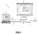
- the present invention may be applied to a projection display system 1 configured as shown for example in Fig.1.
- This projection display system 1 is made up of a projector 2 and a control device 3 controlling the projector 2 and which is connected over a USB (Universal Serial Bus) cable 5 to permit bidirectional packet transmission/reception.
- the control device 3 controls the projector 2 and performs display control responsive to USB mouse signals from a remote controller 4.
- the control device 3 and the projector 2 are interconnected over an RGB (red, green and blue) cable 6 to send display data from the control device 3 to the projector 2 to project light on a display screen 5 to display an image thereon.
- the projector 2 includes therein an optical system and so forth and, based on display data supplied from the control device 3 over the RGB cable 6, projects light onto the display screen 5 to display an image on the display screen S.
- This projector 2 also is provided with a serial interface pursuant to the USB standard and connects to the control device 3 while connecting over a USB cable 5 to an external peripheral equipment having a USB interface.
- the external peripheral equipment having a USB interface is referred to below as a USB device.
- This projector 2 sends the USB mouse signals to the control device 3 over the USB cable 5 responsive to actuation of the remote controller 4 and is fed with projector control signals and pointer control signals for controlling various operations from the control device 3 over the USB cable 5 and with display data for demonstrating a picture on the display screen S over the RGB cable 6.
- the detailed structure of this projector 2 will be explained subsequently.
- the control device 3 is made up e.g., of a personal computer and is operated in accordance with a projector control program (program name: Projector Station Life) recorded on an inner recording medium to generate projector control signals to control the projector 2.
- a projector control program program name: Projector Station Life
- This control device 3 includes a serial interface, such as USB, which is an interface similar to the projector 2, and is connected over the USB cable 5 and the RGB cable 6.
- This control device 3 outputs the projector control signals, pointer control signals and the display data to the projector 2 to control the projector 2 and to the USB devices connected to the projector 2.
- This control device 3 also includes an operating input unit, such as a keyboard, and is responsive to actuation of e.g., a keyboard by a user to boot a projector control program and other application programs to execute processing operations such as controlling the projector 2 or generating display data.
- an operating input unit such as a keyboard
- actuation of e.g., a keyboard by a user to boot a projector control program and other application programs to execute processing operations such as controlling the projector 2 or generating display data.
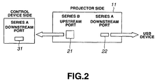
- the above-described projector 2 and control device 3 are interconnected as shown in Fig.3. That is, the projector 2 is provided with a hub 11 having an upstream port 21 and a downstream port 22 conforming to the USB standard.
- the control device 3 is provided with a downstream port 31 connected to the USB cable 5.
- the USB device includes at least an upstream port.
- the upstream port 21 of the projector 2 is connected to the downstream port 31 of the control device 3 over the USB cable 5 and the RGB cable 6, whilst the downstream port 22 of the projector 2 is connected to the upstream port of the USB device over the USB cable 5.
- control device 3 controls the protocol as a host to control the projector 2 and the USB device connected to the projector, as targets. At this time, bi-directional communication is executed between the control device 3, projector 2 and the USB device in the form of packets including additional information such as addresses of the destination of data transmission or data sorts.
- the control device 3 in transferring display data between the projector 2 and the USB device, the control device 3 first generates and transmits a token packet including addresses of a data receiving side. Next, the control device 3 transmits a data packet and, after the data packet has arrived at the data receiver, it transmits a handshaking packet. If the data receiving side has received the data packet as normally, it transmits a packet including an ACK to the control device 3. If conversely the data receiving side has failed to receivethe data packet, it transmits a packet including a NAK to the control device 3. The control device 3 performs isochronous transfer, interrupt transfer, control transfer or bulk transfer, depending on the type of data, such as display data transmitted to the projector 2 or the USB device, or on the projector control signals.
- the remote controller 4 includes various buttons, as shown in Fig.3. These buttons are actuated by a user to generate operating input signals to output the generated operating input signals which are output to the controller as an IR light L.
- This remote controller 4 includes an IR outputting unit 41, outputting the IR light L, a power source button 42 for turning the power source of the projector 2 on or off, and function buttons 43, 44 for switching the application programs booted by the control device 3 in case of demonstration on the projector 2.
- the remote controller 4 also includes input changeover buttons 45 to 48 for switching the types of the display data input from the control device 3 to the projector 2, a pointer control button 49 for controlling a pointer demonstrated on the display screen S, a click button 50 for performing control corresponding to left click of the mouse operating as a pointing device and a click button 51 for performing control corresponding to right click of the mouse.
- the remote controller 4 includes an image on/off button for start/stop of image display and an acoustic on/off button 53 for start/stop of the acoustic output.
- the control device 3 includes a series A connector 32, connected to the USB cable 5, a controller 33, an operating input unit 34, a display unit 35, and an RSB connector 36 connected to the RGB cable 6.
- the operating input unit 34 includes e.g., a keyboard and is actuated by a user to generate an operating input signal which is routed to the controller 33.
- the controller 33 performs processing in accordance with the general-purpose OS (operating system) such as, for example, Microsoft Windows (registered trademark).
- This controller 33 controls the USB device connected to the projector 2 and the USB device connected ot he projector 2.
- the controller 33 When performing control in accordance with an operating input signal from the operating input unit 34 or the USB mouse signals, the controller 33 reads in the projector control program to generate projector control signals and pointer control signals. When executing control of the USB device connected to the projector 2, the controller 33 executes a control program in keeping with the USB device connected to he projector 2.
- the controller 33 also boots an application program in keeping with the operating input signal or the USB mouse signals, such as Microsoft Power Point (registered trademark), to generate display data for demonstration on the display screen S.
- This controller 33 converts the data generated by the application program into RGB to generate display data.
- the controller 33 causes the so-generated RGB display data to be displayed through RSB connector 36 and RGB cable 6 on the projector 2. The detailed operation of the control device 3 will be explained subsequently.
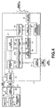
- the projector 2 includes the hub 11, as described above, a series B connector 12 for receiving a projector control signal and a pointer control signal from the control device 3, and a series A connector 13 connected to the USB connector.
- the projector 2 also includes an IR light receiver 14 for receiving the IR light L from the remote controller 4, a signal conversion processor 15 and a USB mouse processor 16.
- the projector 2 includes a USB projector processor 17, connected to the hub 11, a projection display unit 18 for actuating an optical system, not shown, to project light on the display screen S, and a display controller 19 for controlling display contents demonstrated on the projection display unit 18.
- a series A plug of the USB cable 5 To the series A connector 32 of the control device 3 is inserted a series A plug of the USB cable 5, whereas, to the series B connector 12 of the upstream port 21 of the projector 2 and to the series A connector 13 of the downstream port 22 of the projector 22, a series B plug and a series A plug of the USB cable 5 are inserted, respectively.
- This projector 2 is recognized by the control device 3 as three USB devices, namely the hub 11 and the USB mouse function and the USB projector function, connected to the lower order side of the control device 3.
- the series B connector 12 is connected to the series A connector 32 of the control device 3 over the USB cable 5, while being connected to the hub 11.
- the series B connector 12 is fed with the projector control signal and the pointer control signal from the control device 3 to output the signals to the hub 11.
- the series B connector 12 also outputs a packet input from the hub 11 to output the packet overt the USB cable 5 to the control device 3.
- the hub 11 conforming to the USB standard, references to the PID included in the input packet to supervise the packet input/output.
- This hub 11 includes an upstream port 21, connected to the series B connector 12, a series A connector 13, a USB mouse processor 16a, downstream ports 22a to 22c, connected to the USB projector processor 17, and a hub controller 23 for supervising the packet input/output.
- the upstream port 21 is connected to the series B connector 12 and to the hub controller 23 and outputs a packet from the series B connector 12 to the hub controller 23, while outputting a packet from the hub controller 23 to the series B connector 12.
- the downstream port 22 includes a downstream port 22a, connected to the series A connector 13, a downstream port 22b, connected to the USB mouse processor 16, and a downstream port 22c, connected to the USB projector processor 17.
- the downstream port 22a outputs a packet from the hub controller 23 to the series A connector 13, while outputting a packet from the series A connector 13 to the hub controller 23.
- the downstream port 22b outputs a packet from the hub controller 23 to the USB mouse processor 16, while outputting a packet from the USB mouse processor 16 to the hub controller 23.
- the downstream port 22c outputs a packet from the hub controller 23 to the USB projector processor 17, while outputting a packet from the USB projector processor 17 to the hub controller 23.
- the hub controller 23 is connected to the upstream port 21 and to the downstream port 22.
- the hub controller 23 references to a PID, indicating the type of the packet appended to the packet from the upstream port 21, to output the packet to one of the downstream ports 22a and 22b.
- the hub controller 23 also references to a packet from each downstream port 22 to output the packet to an other downstream port 22 or to the upstream port 21.
- the series A connector 13 is provided for connection to a USB device connected to the projector 2. To this series A connector 13 is connected the USB cable 5 to input or output packets for the USB device.
- the IR light receiver 14 receives IR light L indicating an operating input signal responsive to actuation of the aforementioned buttons 42 to 53.
- the IR light receiver 14 outputs detection signals corresponding to the IR light L to the display controller 19 and to the signal conversion processor 15.
- the signal conversion processor 15 performs an operation of converting the detection signal from the IR light receiver 14 into data that can be included into a packet in the USB mouse processor 16.
- the USB mouse processor 16 is connected to the signal conversion processor 15 and to the downstream port 22b. This USB mouse processor 16 converts the data from the signal conversion processor 15 into USB mouse signals issued when the mouse pursiuantto the USB is actuated. The USB mouse processor 16 generates a packet including convered USB mouse signals to output the resulting packet to the hub 11.
- the USB projector processor 17 is connected to the display controller 19 and to the downstream port 22c and operates for outputting a packet inclusive of the data from the display controller 19 and the projector control signal to the downstream port 22 and for interpreting the packet from the downstream port 22 to output the packet to the display controller 19.
- the projection display unit 18 includes an optical system and is responsive to display data from the display controller 19 to project light to display an image on the display screen S.
- This display controller 19 is fed not only with display data from the control device 3 via RGB connector 20 but also with a display control signal from the display controller 19.
- the display controller 19 is connected to the USB projector processor 17, projection display unit 18 and to the IR light receiver 14.
- the display controller 19 controls the contents demonstrated on the projection display unit 18, while generating a projector control signal, representing the state of the projector 2 and so forth, to output the so-generated control signal to the USB projector processor 17.
- the display controller 19 outputs a display control signal to the projection display unit 18 to shift a pointer included in an image demonstrated on the projection display unit 18 responsive to a detection signal from the IR light receiver 14.
- the display controller 19 controls the projection display unit 18 for changing the picture quality setting for an image demonstrated on the projection display unit 18 in accordance with a projector control signal from the USB projector processor 17 to the effect that the picture quality setting is to be changed. Moreover, the display controller 19 is fed with display data through the RGB cable 6 to output the data to the projection display unit 18 to display a picture corresponding to the display data.
- the control device 3 causes a projector control signal indicating e.g., a command for controlling the projector 2 to be issued as output to the projector 2 over the USB cable 5, while a projector control signal indicating e.g., the state of the projector 2 is output from the projector 2 to the control device 3 to permit bidirectional transmission/reception of the projector control signal.
- a projector control signal indicating e.g., a command for controlling the projector 2 to be issued as output to the projector 2 over the USB cable 5
- a projector control signal indicating e.g., the state of the projector 2 is output from the projector 2 to the control device 3 to permit bidirectional transmission/reception of the projector control signal.
- an operating input signal responsive to actuation of the remote controller 4, is output as a USB mouse signal from the projector 2 to the control device 3, whilst a pointer control signal is generated in the controller 33 of the control device 3 and sent to the projector 2 as output.
- the USB device is to be controlled by the controller 33 of the control device 3, the control signal for controlling the USB device or data such as still image data is included in a packet, based on the information input from the USB device to the control device 3, and is issued as output to the USB device through the projector 2, whereby bidirectional data transmission/reception becomes feasible between the USB device and the control device 3.
- the control device 3 recognizes the projector 2 as three USB devices, namely the hub 11 and the USB mouse function and the USB projector function, both connected to the hub 11.
- the controller 33 of the control device 3 retrieves the connected projector 2 by executing the projector control program.
- the USB projector processor 17 of the projector 2 is responsive thereto to acquire from the display controller 19 the information including the projector type name of the projector 2, serial number thereof, and the function thereof that can be set, generates a packet including this information and transmits the so-generated packet to the control device 3. So, the controller 33 recognizes the projector 2 to be controlled by the projection display unit 18.
- the projector 2 generates, in the display controller 19, the information such as the status or the picture quality adjustment function in displaying the picture on the projection display unit 18, and causes this information to be included in the USB projector processor 17 in the packet to transmit the resulting packet to the control device 3.
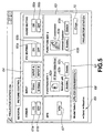
- the controller 33 of the control device 3 executes the projector control program, responsive to the actuating input signal from the operating input unit 34, or to the USB mouse signal to cause a projector control picture, such as is shown in Fig.5, to be demonstrated on the display unit 35.
- the controller 33 causes the projector control picture to be demonstrated on the display unit 35, while transmitting a projector control signal testifying to the demonstration of the projector control picture and display data representing a projector control picture to the projector 2 for demonstrating the projector control picture on the display screen 5.
- the controller 33 demonstrates an operating control picture (GENERAL) and a picture quality setting picture (PICTURE CONTROL), as distinguished by a tab indicated on an upper left part of the screen, as a projector control screen.
- GENERAL operating control picture
- PICTURE CONTROL picture quality setting picture
- the controller 33 demonstrates, as the operation control picture, power source button display units 61a, 61b, for turning the power source of the projector on or off, function button displays 62, 63 for switching the application programs for generating the display data, an input changeover button 64 for switching the type of the display data input from the control device 3 to the projector 2, picture on/off button displays 65a, 65b for start/stop of picture display, acoustic on/off button displays 66a, 66b for start/stop of acoustic output, an APA button display 67, a projector selection display (Model Select) 68 for representing the name of the device, th picture quality for whjich is to be adjusted, a bucket transmission/reception display (Send, Receive) 69 indicating that a packet is to be transmitted/received between the projectr 2 and the control device 3, and a screen end display (close) 70.
- power source button display units 61a, 61b for turning the power source of the projector on or off
- the controller 33 also demonstrates, as the function button displays 62, 63, application program displays 62a, 63a, for demonstrating the application program when a picture is to be displayed by the projector 2, allotting button displays 62b, 63b indicating the buttons for allotting the application programs, deletion button displays 62c, 63c indicating buttons for deleting the allotted application programs, and direct slide show indications 62d, 63d for switching the function on/off when the Microsoft power point is registered as the application program.
- the controller 33 is responsive to the inputting of the USBb mouse signal, testifying toie the selection of the variious button displays 61 to 70 demonstrated on the display unit 35, as a result of actuation of the pointign device provided in the operating input unit 34, to transmit projector control signals for controlling the projector 2 or the display data for demonstrating the picture on the display screen S to the projector 2 over the USB cable 5 or the RGB cable 6.
- the controller 33 is also responsive to the inputting from the projector 2 of a packet incluyding the USB mouse signal testifying to selection of the button displays 61 to 70 demonstrated on the display screen S as a result of actuation of the remote controller 4, to generate a projector control signal adapted for controlling the projector 2 to transmit the generated control signal through the series A connector 32 to the projector 2 ot to output display data for demonstrating a picture on the display screen S over the RGB cable 6.
- the display controller 19 of the projector 2 is also responsive thereto to permit the projector control signal from the control device 3 to be input from the USB mouse processor 16 or to permit display data to be input to control the projection display unit 18 responsive to the projector control signal. Moreover, the display controller 19 also outputs display data to the projection display unit 18 to drive the optical system of the projection display unit 18 to demonstrate the picture on the display screen S.
- the controller 33 If fed with an operating input signal testifying to the selection of a tab of a picture quality setting screen (PICTURE CONTROL), or with the USB mouse signal, the controller 33 demonstrates the picture quality setting picture, shown in Fig.6, on the display unit 35 or on the display screen S. At this time, the controller 33 displays the picture quality setting picture responsive to the outputting of the projector control signal demanding the picture quality setting enabling items of the display controller 19 of the projector 2 in accordance with the information included in the input packet.
- PICTURE CONTROL Picture CONTROL
- the controller 33 demonstrates, as the picture quality setting picture, a contrast adjustment display (contrast) 71 for adjusting the contrast, a brightness adjustment display (brightness) 72 for adjusting the brightness, a color adjustment display (color) 73 for adjusting the color, a hue adjustment display (hue) for adjusting the hue, a sharpness adjustment display (sharpness) 75 for adjusting the sharpness and automatic adjustment display (default) 76 for automating the picture quality setting.
- a contrast adjustment display (contrast) 71 for adjusting the contrast
- a brightness adjustment display (brightness) 72 for adjusting the brightness
- color adjustment display (color) 73 for adjusting the color
- hue adjustment display hue adjustment display
- a sharpness adjustment display (sharpness) 75 for adjusting the sharpness
- automatic adjustment display (default) 76 for automating the picture quality setting.
- the controller 33 also includes a volume display (volume) 77 for adjusting the display area (volume), a color system display 78 for switching color representation for AUTO (automatic control), NTSC (National Television System Committee) picture or PAL (Phase Alternation by Line) picture, picture switching display (direct picture) 79 for switching color representation for black color, color temperature representation (COLOR TEMP) 80, selective projector representation (Model Select) 81, packet transmission/reception representation (Send, Receive) 82, setting end display 83, data form representation (GAMMA MODE) 84 for selecting display data form (GRAPHICS, TEXT), and RGB enhancer adjustment display (REG ENHANCER) 85 for making adjustment concerning the RGB enhancer.
- a volume display for adjusting the display area (volume)
- a color system display 78 for switching color representation for AUTO (automatic control)
- NTSC National Television System Committee
- PAL Phase Alternation by Line
- picture switching display (direct picture) 79 for switching color representation for black color
- the controller 33 invalidates the respective displays 71 to 85 of the picture quality setting screen and makes display to that effect.
- the controller 33 generates a packet including a projector control signal for adjusting the picture quality of the picture demonstrated on the display screen S, responsive to the inputting of the operating input signal or the USB mouse signal stating that the operating input unit 34 or the remote controller 4 has been operated and selected the displayed representations 71 to 85.
- the controller 33 sends the packet so generated to the projector 2 through the series A connector 32.
- the controller 33 generates a packet including a projector control signal for adjusting the picture quality of the picture demonstrated on the display screen S. responsive to the inputting from the projector of the operating input signal or the USB mouse signal stating that the operating input unit 34 or the remote controller 4 has been operated and selected the displayed representations 71 to 85. The controller 33 sends the packet so generated to the projector 2 through the series A connector 32. 68.
- the controller 33 demonstrates picture quality setting pictures 90, 91 shown in Fig.7.
- the controller 33 is then responsive to whether or not the picture quality setting display is possible, depending on the setting state of each projector and settable items to display a picture quality setting screen.
- the controller 33 acquires the information including the projector type name, serial number, an settable functions, from the display controller 19 to set the projector selection display 81 of the picture quality setting picture 90 as VPL-PX30 (S/N: 9999999), while setting the projector selection display 81 of the picture quality setting picture 91 as VPL-CS1 (S/N: 0000122).
- the controller 33 invalidates the brightness adjustment display 72, color adjustment display 73, hue adjustment display 74 and sharpness adjustment display 75, and displays the picture quality setting picture 90.
- the controller 33 invalidates the brightness adjustment display 72, color adjustment display 73, hue adjustment display 74 and sharpness adjustment display 75, while demonstrating a picture quality setting picture 91 which sets the RGB enhancer adjustment display 85 to non-display.
- the controller 33 is fed from the projector 2 with a packet including a USB mouse signal stating that, as a result of the user actuating the remote controller 4, an icon designating an application program represented on the desktop, such as Internet Explorer, a registered trademark, has been dragged and dropped from the desktop screen area to an area of an application program display 63 on the projector control picture, as shown in Fig.8.
- a packet including a USB mouse signal stating that, as a result of the user actuating the remote controller 4, an icon designating an application program represented on the desktop, such as Internet Explorer, a registered trademark, has been dragged and dropped from the desktop screen area to an area of an application program display 63 on the projector control picture, as shown in Fig.8.
- the controller 33 is responsive thereto to register the application program, specified by the icon, as an application program for demonstrating a picture on the display screen S by the projector 2 to make presentations.
- the controller 33 also outputs to the projector 2 display data for demonstrating a projector control picture which has demonstrated the icon 101 thus dragged and dropped in the program display portion 63a, as shown in Fig.9.
- the controller 33 If fed with the operating input signal or the USB mose signal, stating that a picture is to be demonstrated based on display data prepared in accordance with the registered application program, the controller 33 sends the display data prepared in accordance with the registered application program through the RGB cable 6 to the projector 2.
- the controller 33 executes the direct slide show function of the Microsoft Power Point to output the display data over the RGB cable 6 to the projector 2. If the controller 33 is fed from the remote controller 4 with the USB mouse signal responsive to the pressing of the left click button 50, the controller 33 proceeds to turn over the pages of the displayed picture. If, on the other hand, the controller 33 is fed from the projector 2 with the USB mouse signal responsive to the pressing of the function button 43 of the remote controller 4, the controller 33 proceeds to terminate the Microsoft power Point.
- the above-described projection display system 1 includes a USB interface in the controller 3 and a hub 11 conforming to the USB in the projector 2, and connects the USB mouse processor 16, recognized as the USB projector function, and the USB projector processor 17, recognized as the USB projector function, to the hub 11, it is possible to transmit/receive a packet demonstrated on the display screen S to perform projector control and pointer control over the sole USB cable 5 between the control device 3 and the projector 2.
- it is unnecesary to provide the pointer controlling cable and the projector controlling cable separartely from each other, thereby simplifying the system designing.
- the present projection display system 1 in which the projector 2 and the control device 3 are provided with the interface conforming to the USB, it is unnecessary to mount or dismount the cables with the power source of the control device 3 off to provide for a stabilized system.
- the system can be constructed using the universal hub 11 and USB cable 5, thus reducing the cost invlved in software and hardware.
- data transmission/reception can be made at a higher speed than if data is transmitted/received over e.g., an RS232C, thus facilitating the user operation.
- USB series A connector Since only one USB series A connector is loaded on the portable personal computer, with the projection display system 1, an other USB device cannot be connected if the projector is already connected. However, since the projector 2 is provided with the hub 11, the other USB device can be connected to the projector 2 to provide for facilitated system extension.
- the USB mouse signal may be input to the controller 3 through the series A connector 13, hub 11 and the series B connector 12, to enable the control device 3 to be operated by the mouse connected to the projector 2.
- the control device 3 is mounted at a remote site from the user, the USB mouse connected to the projector 2 can be operated to execute the projector control program or other application program of the control device 3.
- the projector 2 and the control device 3 are provided with an interface conforming to the USB standard, and are interconnected by the USB cable 5 and the RGB cable 6. It is however possible that the projector 2 and the control device 3 are provided with an interface conforming to the IEEE (The Institute of Electrical and Electronics Engineers) 1394 standard.
Abstract

Description
- This invention relates to projection display apparatus and projection display systems in which data is furnished from and light is projected to display an image.
- A display system is known in which a liquid crystal projector is controlled by a personal computer as a control device for making presentations or the like. In such display system, the projector is controlled by the personal computer to project an image on the screen.
- When a pointer position displayed along with an image using this display system is moved to make presentation, a projector and a remote controller making infrared communication are frequently used. That is, the remote controller is actuated by a user to generate an actuating input signal to output the signal as the IR light to an IR light receiving portion of the projector. This causes the projector to output an actuating input signal over a dedicated cable to the personal computer to move the pointer position responsive to the user actuation for display.
- In the above-described display system, the personal computer and the projector are interconnected over a projector control cable for controlling the projector, a pointer dedicated cable for controlling the pointer by a remote controller annexed to the projector, and over an RGB cable used for transmitting RGB picture data from the personal computer to the projector.
- For controlling the projector, the projector is controlled by the personal computer by a serial interface such as RS-232C and a projector control cable pursuant to RS-232C. In such display system, a projector control signal for controlling the projector is output from the personal computer over the RS232C cable to the projector.
- When displaying a picture on a display screen by projecting the light by the projector, the personal computer inputs a projector control signal to the projector over a projector control cable, whilst picture data to be displayed on the display screen via RGB cable is input to the projector.
- If, when a picture is displayed on the display screen, a remote controller or a pointing device of the personal computer is acted on by the user, a pointer controlling signal is input from the personal computer over a pointer dedicated cable, such as PS2 cable, to the projector.
- However, in this display system, the interface and the cable used for transmitting e.g., a projector control signal from the personal computer to the projector, as well as the interface and the cable used for controlling the pointer position specified by e.g., the remote controller, are of different standards. So, in the above-mentioned display system, it has been necessary to provide the interface and the cable for transmitting/receiving the control signal etc separately from the interface and the cable for performing pointer control.
- In order to overcome such inconvenience, it has been contemplated to provide an interface and the cable for transmitting/receiving the control signal etc and the cable for performing pointer control in common. However, there is a limit in the number of connectors provided in the small-sized portable personal computer, such that the connector is taken up by the projector control cable used for interconnecting the projector and the portable personal computer to render it impossible to make connections to other devices, such as a mouse.
- Moreover, if, in making presentation using the above-described display system in e.g., a small conference hall, the pointer control employing a remote controller emitting the IR light is used, the user operation making the presentation tends to be complicated.
- In addition, if, in the conventional display system, employing a projector, plural projectors are used, dedicated switchers etc., adapted for coping with e.g., RS 485, need to be used, thus raising the cost. In such conventional system, the circuit load in the projector tends to be increased.
- It is therefore an aim of at least an embodiment of the present invention to provide a projection display apparatus and system that are able to improve the operability of a system for controlling a displayed picture using a control device.
- In one aspect, the present invention provides a projection display apparatus connected to a control device as a host through a serial interface, in which data is transmitted/received bi-directionally to display a picture on a display screen. The apparatus includes display means fed from the control device with display data and which is illuminated with projected light to display a picture represented by the display data, input/output means connected to the control device adapted for generating display control signals controlling the display means and to at least one external peripheral equipment to input/output data based on the supplementary information appended to input data, and display control means for controlling a picture demonstrated by the display means based on a display control signal input through the input/output means.
- In this projection display apparatus, the control device and the external peripheral equipment are connected to input/output means. Display is made on display means based on a control signal from the control device or a control signal generated by the control device by the operation of the external peripheral equipment.
- In another aspect, the present invention provides a projection display system in which a control device as a host and a projection display apparatus as a target controlled by the control device are interconnected over a serial interface, and in which data transmission/reception is made bi-directionally at least between the control device and the projection display apparatus to demonstrate a picture by the projection display apparatus on a display screen. The projection display apparatus includes display means fed from the control device with display data and which is illuminated with projected light to display a picture represented by the display data, input/output means connected to the control device adapted for generating display control signals controlling the display means and to at least one external peripheral equipment to input/output data based on the supplementary information appended to input data, and display control means for controlling a picture demonstrated by the display means based on a display control signal input through the input/output means. The control device includes input/output means connected to the projection display apparatus and control means for outputting display control signals and display data to the projection display apparatus and to the external peripheral equipment connected to the projection display apparatus to cause the projection display apparatus to demonstrate a picture on the projection display apparatus.
- In this projection display system, the control device and the external peripheral equipment are connected to the projection display apparatus. Display is made on the projection display apparatus based on a control signal from the control device or a control signal generated by the control device by the operation of the external peripheral equipment.
- With the projection display apparatus, according to the present invention, the control device and the external peripheral equipment are connected to input/output means, and display may be made on the display means based on the control signal from the control device or on the control signal generated by the control device by operation of the external peripheral equipment. By connecting an operating input device to, for example, the projection display apparatus, an operating input signal can be accorded to the control device to control a picture demonstrated on the display means to improve the operating performance of a system designed to control the displayed picture with aid of the control device.
- With the projection display system embodying the present invention, the control device and the external peripheral equipment are connected to the projection display apparatus, and display may be made on the projection display apparatus based on the control signal from the control device or on the control signal generated by the control device by operation of the external peripheral equipment. By connecting an operating input device to, for example, the projection display apparatus, an operating input signal can be accorded to the control device to control a picture demonstrated on the projection display apparatus to improve the operating performance of the system designed to control the displayed picture with the aid of the control device.
- The invention will now be described by way of example with reference to the accompanying drawings, throughout which like parts are referred to by like references, and in which:
- Fig.1 shows the configuration of a projection display system embodying the present invention.
- Fig.2 illustrates the state of interconnection of respective components making up the projection display system embodying the present invention.
- Fig.3 is a perspective view showing various buttons provided in the remote controller provided in the projection display system embodying the present invention.
- Fig.4 is a block diagram showing the configuration of the projector and a control device provided in the projection display system embodying the present invention.
- Fig.5 shows a projector control picture displayed on a display unit or a display screen of the control device.
- Fig.6 shows picture quality setting picture displayed on the display unit or the display screen of the control device.
- Fig.7 shows a picture quality setting picture displayed on the display unit or the display screen of the control device when plural projectors are connected to the control device.
- Fig.8 illustrates the processing for registering an application program used for generating display data demonstrated on the display screen.
- Fig.9 illustrates the processing of registering an application program used for generating display data demonstrated on the display screen.
-
- The present invention may be applied to a
projection display system 1 configured as shown for example in Fig.1. - This
projection display system 1 is made up of aprojector 2 and acontrol device 3 controlling theprojector 2 and which is connected over a USB (Universal Serial Bus)cable 5 to permit bidirectional packet transmission/reception. Thecontrol device 3 controls theprojector 2 and performs display control responsive to USB mouse signals from aremote controller 4. In thisprojection display system 1, thecontrol device 3 and theprojector 2 are interconnected over an RGB (red, green and blue)cable 6 to send display data from thecontrol device 3 to theprojector 2 to project light on adisplay screen 5 to display an image thereon. - The
projector 2 includes therein an optical system and so forth and, based on display data supplied from thecontrol device 3 over theRGB cable 6, projects light onto thedisplay screen 5 to display an image on the display screen S. - This
projector 2 also is provided with a serial interface pursuant to the USB standard and connects to thecontrol device 3 while connecting over aUSB cable 5 to an external peripheral equipment having a USB interface. The external peripheral equipment having a USB interface is referred to below as a USB device. Thisprojector 2 sends the USB mouse signals to thecontrol device 3 over theUSB cable 5 responsive to actuation of theremote controller 4 and is fed with projector control signals and pointer control signals for controlling various operations from thecontrol device 3 over theUSB cable 5 and with display data for demonstrating a picture on the display screen S over theRGB cable 6. The detailed structure of thisprojector 2 will be explained subsequently. - The
control device 3 is made up e.g., of a personal computer and is operated in accordance with a projector control program (program name: Projector Station Life) recorded on an inner recording medium to generate projector control signals to control theprojector 2. - This
control device 3 includes a serial interface, such as USB, which is an interface similar to theprojector 2, and is connected over theUSB cable 5 and theRGB cable 6. Thiscontrol device 3 outputs the projector control signals, pointer control signals and the display data to theprojector 2 to control theprojector 2 and to the USB devices connected to theprojector 2. - This
control device 3 also includes an operating input unit, such as a keyboard, and is responsive to actuation of e.g., a keyboard by a user to boot a projector control program and other application programs to execute processing operations such as controlling theprojector 2 or generating display data. - The above-described
projector 2 andcontrol device 3 are interconnected as shown in Fig.3. That is, theprojector 2 is provided with ahub 11 having anupstream port 21 and adownstream port 22 conforming to the USB standard. Thecontrol device 3 is provided with adownstream port 31 connected to theUSB cable 5. The USB device includes at least an upstream port. - In the
projection display system 1, theupstream port 21 of theprojector 2 is connected to thedownstream port 31 of thecontrol device 3 over theUSB cable 5 and theRGB cable 6, whilst thedownstream port 22 of theprojector 2 is connected to the upstream port of the USB device over theUSB cable 5. - In this
projection display system 1, thecontrol device 3 controls the protocol as a host to control theprojector 2 and the USB device connected to the projector, as targets. At this time, bi-directional communication is executed between thecontrol device 3,projector 2 and the USB device in the form of packets including additional information such as addresses of the destination of data transmission or data sorts. - That is, in transferring display data between the
projector 2 and the USB device, thecontrol device 3 first generates and transmits a token packet including addresses of a data receiving side. Next, thecontrol device 3 transmits a data packet and, after the data packet has arrived at the data receiver, it transmits a handshaking packet. If the data receiving side has received the data packet as normally, it transmits a packet including an ACK to thecontrol device 3. If conversely the data receiving side has failed to receivethe data packet, it transmits a packet including a NAK to thecontrol device 3. Thecontrol device 3 performs isochronous transfer, interrupt transfer, control transfer or bulk transfer, depending on the type of data, such as display data transmitted to theprojector 2 or the USB device, or on the projector control signals. - The
remote controller 4 includes various buttons, as shown in Fig.3. These buttons are actuated by a user to generate operating input signals to output the generated operating input signals which are output to the controller as an IR light L. - This
remote controller 4 includes anIR outputting unit 41, outputting the IR light L, apower source button 42 for turning the power source of theprojector 2 on or off, andfunction buttons control device 3 in case of demonstration on theprojector 2. Theremote controller 4 also includesinput changeover buttons 45 to 48 for switching the types of the display data input from thecontrol device 3 to theprojector 2, apointer control button 49 for controlling a pointer demonstrated on the display screen S, aclick button 50 for performing control corresponding to left click of the mouse operating as a pointing device and aclick button 51 for performing control corresponding to right click of the mouse. In addition, theremote controller 4 includes an image on/off button for start/stop of image display and an acoustic on/offbutton 53 for start/stop of the acoustic output. - The structure of the
projector 2 and thecontrol device 3 is explained with reference to Fig.4. - The
control device 3 includes aseries A connector 32, connected to theUSB cable 5, acontroller 33, an operatinginput unit 34, adisplay unit 35, and anRSB connector 36 connected to theRGB cable 6. - The operating
input unit 34 includes e.g., a keyboard and is actuated by a user to generate an operating input signal which is routed to thecontroller 33. - The
controller 33 performs processing in accordance with the general-purpose OS (operating system) such as, for example, Microsoft Windows (registered trademark). Thiscontroller 33 controls the USB device connected to theprojector 2 and the USB device connected ot heprojector 2. - When performing control in accordance with an operating input signal from the operating
input unit 34 or the USB mouse signals, thecontroller 33 reads in the projector control program to generate projector control signals and pointer control signals. When executing control of the USB device connected to theprojector 2, thecontroller 33 executes a control program in keeping with the USB device connected to heprojector 2. - The
controller 33 also boots an application program in keeping with the operating input signal or the USB mouse signals, such as Microsoft Power Point (registered trademark), to generate display data for demonstration on the display screen S. Thiscontroller 33 converts the data generated by the application program into RGB to generate display data. Thecontroller 33 causes the so-generated RGB display data to be displayed throughRSB connector 36 andRGB cable 6 on theprojector 2. The detailed operation of thecontrol device 3 will be explained subsequently. - The
projector 2 includes thehub 11, as described above, aseries B connector 12 for receiving a projector control signal and a pointer control signal from thecontrol device 3, and aseries A connector 13 connected to the USB connector. Theprojector 2 also includes an IRlight receiver 14 for receiving the IR light L from theremote controller 4, asignal conversion processor 15 and aUSB mouse processor 16. Moreover, theprojector 2 includes aUSB projector processor 17, connected to thehub 11, aprojection display unit 18 for actuating an optical system, not shown, to project light on the display screen S, and adisplay controller 19 for controlling display contents demonstrated on theprojection display unit 18. - To the
series A connector 32 of thecontrol device 3 is inserted a series A plug of theUSB cable 5, whereas, to theseries B connector 12 of theupstream port 21 of theprojector 2 and to theseries A connector 13 of thedownstream port 22 of theprojector 22, a series B plug and a series A plug of theUSB cable 5 are inserted, respectively. - This
projector 2 is recognized by thecontrol device 3 as three USB devices, namely thehub 11 and the USB mouse function and the USB projector function, connected to the lower order side of thecontrol device 3. - The
series B connector 12 is connected to theseries A connector 32 of thecontrol device 3 over theUSB cable 5, while being connected to thehub 11. Theseries B connector 12 is fed with the projector control signal and the pointer control signal from thecontrol device 3 to output the signals to thehub 11. Theseries B connector 12 also outputs a packet input from thehub 11 to output the packet overt theUSB cable 5 to thecontrol device 3. - The
hub 11, conforming to the USB standard, references to the PID included in the input packet to supervise the packet input/output. Thishub 11 includes anupstream port 21, connected to theseries B connector 12, aseries A connector 13, a USB mouse processor 16a,downstream ports 22a to 22c, connected to theUSB projector processor 17, and ahub controller 23 for supervising the packet input/output. - The
upstream port 21 is connected to theseries B connector 12 and to thehub controller 23 and outputs a packet from theseries B connector 12 to thehub controller 23, while outputting a packet from thehub controller 23 to theseries B connector 12. - The
downstream port 22 includes adownstream port 22a, connected to theseries A connector 13, adownstream port 22b, connected to theUSB mouse processor 16, and adownstream port 22c, connected to theUSB projector processor 17. Thedownstream port 22a outputs a packet from thehub controller 23 to theseries A connector 13, while outputting a packet from theseries A connector 13 to thehub controller 23. Thedownstream port 22b outputs a packet from thehub controller 23 to theUSB mouse processor 16, while outputting a packet from theUSB mouse processor 16 to thehub controller 23. Thedownstream port 22c outputs a packet from thehub controller 23 to theUSB projector processor 17, while outputting a packet from theUSB projector processor 17 to thehub controller 23. - The
hub controller 23 is connected to theupstream port 21 and to thedownstream port 22. Thehub controller 23 references to a PID, indicating the type of the packet appended to the packet from theupstream port 21, to output the packet to one of thedownstream ports hub controller 23 also references to a packet from eachdownstream port 22 to output the packet to an otherdownstream port 22 or to theupstream port 21. - The
series A connector 13 is provided for connection to a USB device connected to theprojector 2. To thisseries A connector 13 is connected theUSB cable 5 to input or output packets for the USB device. - The IR
light receiver 14 receives IR light L indicating an operating input signal responsive to actuation of theaforementioned buttons 42 to 53. The IRlight receiver 14 outputs detection signals corresponding to the IR light L to thedisplay controller 19 and to thesignal conversion processor 15. - The
signal conversion processor 15 performs an operation of converting the detection signal from the IRlight receiver 14 into data that can be included into a packet in theUSB mouse processor 16. - The
USB mouse processor 16 is connected to thesignal conversion processor 15 and to thedownstream port 22b. ThisUSB mouse processor 16 converts the data from thesignal conversion processor 15 into USB mouse signals issued when the mouse pursiuantto the USB is actuated. TheUSB mouse processor 16 generates a packet including convered USB mouse signals to output the resulting packet to thehub 11. - The
USB projector processor 17 is connected to thedisplay controller 19 and to thedownstream port 22c and operates for outputting a packet inclusive of the data from thedisplay controller 19 and the projector control signal to thedownstream port 22 and for interpreting the packet from thedownstream port 22 to output the packet to thedisplay controller 19. - The
projection display unit 18 includes an optical system and is responsive to display data from thedisplay controller 19 to project light to display an image on the display screen S. Thisdisplay controller 19 is fed not only with display data from thecontrol device 3 viaRGB connector 20 but also with a display control signal from thedisplay controller 19. - The
display controller 19 is connected to theUSB projector processor 17,projection display unit 18 and to the IRlight receiver 14. Thedisplay controller 19 controls the contents demonstrated on theprojection display unit 18, while generating a projector control signal, representing the state of theprojector 2 and so forth, to output the so-generated control signal to theUSB projector processor 17. - The
display controller 19 outputs a display control signal to theprojection display unit 18 to shift a pointer included in an image demonstrated on theprojection display unit 18 responsive to a detection signal from the IRlight receiver 14. - Moreover, the
display controller 19 controls theprojection display unit 18 for changing the picture quality setting for an image demonstrated on theprojection display unit 18 in accordance with a projector control signal from theUSB projector processor 17 to the effect that the picture quality setting is to be changed. Moreover, thedisplay controller 19 is fed with display data through theRGB cable 6 to output the data to theprojection display unit 18 to display a picture corresponding to the display data. - In the above-described
projection display system 1, in which thecontrol device 3 and theprojector 2 are interconnected over theRGB cable 6, display data are fed from thecontroller 33 of thecontrol device 3 to theprojection display unit 18 of theprojector 2. Moreover, in thisprojection display system 1, thecontrol device 3 causes a projector control signal indicating e.g., a command for controlling theprojector 2 to be issued as output to theprojector 2 over theUSB cable 5, while a projector control signal indicating e.g., the state of theprojector 2 is output from theprojector 2 to thecontrol device 3 to permit bidirectional transmission/reception of the projector control signal. Also, in thisprojection display system 1, an operating input signal, responsive to actuation of theremote controller 4, is output as a USB mouse signal from theprojector 2 to thecontrol device 3, whilst a pointer control signal is generated in thecontroller 33 of thecontrol device 3 and sent to theprojector 2 as output. In addition, if, in thisprojection display system 1, the USB device is to be controlled by thecontroller 33 of thecontrol device 3, the control signal for controlling the USB device or data such as still image data is included in a packet, based on the information input from the USB device to thecontrol device 3, and is issued as output to the USB device through theprojector 2, whereby bidirectional data transmission/reception becomes feasible between the USB device and thecontrol device 3. - If, in the above-described
projection display system 1, thecontrol device 3 and theprojector 2 are interconnected, thecontrol device 3 recognizes theprojector 2 as three USB devices, namely thehub 11 and the USB mouse function and the USB projector function, both connected to thehub 11. Thecontroller 33 of thecontrol device 3 retrieves theconnected projector 2 by executing the projector control program. TheUSB projector processor 17 of theprojector 2 is responsive thereto to acquire from thedisplay controller 19 the information including the projector type name of theprojector 2, serial number thereof, and the function thereof that can be set, generates a packet including this information and transmits the so-generated packet to thecontrol device 3. So, thecontroller 33 recognizes theprojector 2 to be controlled by theprojection display unit 18. On the other hand, theprojector 2 generates, in thedisplay controller 19, the information such as the status or the picture quality adjustment function in displaying the picture on theprojection display unit 18, and causes this information to be included in theUSB projector processor 17 in the packet to transmit the resulting packet to thecontrol device 3. - When a picture is to be demonstrated on the display screen S in the
projection display system 1, thecontroller 33 of thecontrol device 3 executes the projector control program, responsive to the actuating input signal from the operatinginput unit 34, or to the USB mouse signal to cause a projector control picture, such as is shown in Fig.5, to be demonstrated on thedisplay unit 35. On the other hand, thecontroller 33 causes the projector control picture to be demonstrated on thedisplay unit 35, while transmitting a projector control signal testifying to the demonstration of the projector control picture and display data representing a projector control picture to theprojector 2 for demonstrating the projector control picture on thedisplay screen 5. - Referring to Fig.5, the
controller 33 demonstrates an operating control picture (GENERAL) and a picture quality setting picture (PICTURE CONTROL), as distinguished by a tab indicated on an upper left part of the screen, as a projector control screen. - The
controller 33 demonstrates, as the operation control picture, power sourcebutton display units input changeover button 64 for switching the type of the display data input from thecontrol device 3 to theprojector 2, picture on/offbutton displays button displays APA button display 67, a projector selection display (Model Select) 68 for representing the name of the device, th picture quality for whjich is to be adjusted, a bucket transmission/reception display (Send, Receive) 69 indicating that a packet is to be transmitted/received between theprojectr 2 and thecontrol device 3, and a screen end display (close) 70. - The
controller 33 also demonstrates, as the function button displays 62, 63, application program displays 62a, 63a, for demonstrating the application program when a picture is to be displayed by theprojector 2, allottingbutton displays deletion button displays - The
controller 33 is responsive to the inputting of the USBb mouse signal, testifying toie the selection of the variious button displays 61 to 70 demonstrated on thedisplay unit 35, as a result of actuation of the pointign device provided in the operatinginput unit 34, to transmit projector control signals for controlling theprojector 2 or the display data for demonstrating the picture on the display screen S to theprojector 2 over theUSB cable 5 or theRGB cable 6. - The
controller 33 is also responsive to the inputting from theprojector 2 of a packet incluyding the USB mouse signal testifying to selection of the button displays 61 to 70 demonstrated on the display screen S as a result of actuation of theremote controller 4, to generate a projector control signal adapted for controlling theprojector 2 to transmit the generated control signal through theseries A connector 32 to theprojector 2 ot to output display data for demonstrating a picture on the display screen S over theRGB cable 6. - The
display controller 19 of theprojector 2 is also responsive thereto to permit the projector control signal from thecontrol device 3 to be input from theUSB mouse processor 16 or to permit display data to be input to control theprojection display unit 18 responsive to the projector control signal. Moreover, thedisplay controller 19 also outputs display data to theprojection display unit 18 to drive the optical system of theprojection display unit 18 to demonstrate the picture on the display screen S. - If fed with an operating input signal testifying to the selection of a tab of a picture quality setting screen (PICTURE CONTROL), or with the USB mouse signal, the
controller 33 demonstrates the picture quality setting picture, shown in Fig.6, on thedisplay unit 35 or on the display screen S. At this time, thecontroller 33 displays the picture quality setting picture responsive to the outputting of the projector control signal demanding the picture quality setting enabling items of thedisplay controller 19 of theprojector 2 in accordance with the information included in the input packet. - Referring to Fig.6, the
controller 33 demonstrates, as the picture quality setting picture, a contrast adjustment display (contrast) 71 for adjusting the contrast, a brightness adjustment display (brightness) 72 for adjusting the brightness, a color adjustment display (color) 73 for adjusting the color, a hue adjustment display (hue) for adjusting the hue, a sharpness adjustment display (sharpness) 75 for adjusting the sharpness and automatic adjustment display (default) 76 for automating the picture quality setting. Thecontroller 33 also includes a volume display (volume) 77 for adjusting the display area (volume), acolor system display 78 for switching color representation for AUTO (automatic control), NTSC (National Television System Committee) picture or PAL (Phase Alternation by Line) picture, picture switching display (direct picture) 79 for switching color representation for black color, color temperature representation (COLOR TEMP) 80, selective projector representation (Model Select) 81, packet transmission/reception representation (Send, Receive) 82, settingend display 83, data form representation (GAMMA MODE) 84 for selecting display data form (GRAPHICS, TEXT), and RGB enhancer adjustment display (REG ENHANCER) 85 for making adjustment concerning the RGB enhancer. - If, when the picture quality setting screen shown in Fig.6 is to be displayed, an adjustment item that cannot be set is verified to exist in the
projector 2 or the USB device, selected by theselective projector representation 81 and which is the object of setting of picture quality, thecontroller 33 invalidates therespective displays 71 to 85 of the picture quality setting screen and makes display to that effect. - The
controller 33 generates a packet including a projector control signal for adjusting the picture quality of the picture demonstrated on the display screen S, responsive to the inputting of the operating input signal or the USB mouse signal stating that the operatinginput unit 34 or theremote controller 4 has been operated and selected the displayedrepresentations 71 to 85. Thecontroller 33 sends the packet so generated to theprojector 2 through theseries A connector 32. - The
controller 33 generates a packet including a projector control signal for adjusting the picture quality of the picture demonstrated on the display screen S. responsive to the inputting from the projector of the operating input signal or the USB mouse signal stating that the operatinginput unit 34 or theremote controller 4 has been operated and selected the displayedrepresentations 71 to 85. Thecontroller 33 sends the packet so generated to theprojector 2 through theseries A connector 32. 68. - If an other projector is connected to these 13 of the
projector 2, that is if two projectors are connected to thecontroller 3, thecontroller 33 demonstrates picturequality setting pictures controller 33 is then responsive to whether or not the picture quality setting display is possible, depending on the setting state of each projector and settable items to display a picture quality setting screen. - That is, the
controller 33 acquires the information including the projector type name, serial number, an settable functions, from thedisplay controller 19 to set theprojector selection display 81 of the picturequality setting picture 90 as VPL-PX30 (S/N: 9999999), while setting theprojector selection display 81 of the picturequality setting picture 91 as VPL-CS1 (S/N: 0000122). - If, for example, the first projector is not provided with the brightness adjustment function, color adjustment function, hue adjustment function or sharpness adjustment function, the
controller 33 invalidates thebrightness adjustment display 72,color adjustment display 73,hue adjustment display 74 andsharpness adjustment display 75, and displays the picturequality setting picture 90. - If, for example, the second projector is not provided with the brightness adjustment function, color adjustment function, hue adjustment function, sharpness adjustment function nor with the RGB enhancer, the
controller 33 invalidates thebrightness adjustment display 72,color adjustment display 73,hue adjustment display 74 andsharpness adjustment display 75, while demonstrating a picturequality setting picture 91 which sets the RGBenhancer adjustment display 85 to non-display. - An example in which the projector control picture shown in Fig.5 is displayed on the display screen S, and the
controller 33 specifies an application program to display a picture on the display screen S, is hereinafter explained. - First, the
controller 33 is fed from theprojector 2 with a packet including a USB mouse signal stating that, as a result of the user actuating theremote controller 4, an icon designating an application program represented on the desktop, such as Internet Explorer, a registered trademark, has been dragged and dropped from the desktop screen area to an area of anapplication program display 63 on the projector control picture, as shown in Fig.8. - The
controller 33 is responsive thereto to register the application program, specified by the icon, as an application program for demonstrating a picture on the display screen S by theprojector 2 to make presentations. Thecontroller 33 also outputs to theprojector 2 display data for demonstrating a projector control picture which has demonstrated theicon 101 thus dragged and dropped in theprogram display portion 63a, as shown in Fig.9. - If fed with the operating input signal or the USB mose signal, stating that a picture is to be demonstrated based on display data prepared in accordance with the registered application program, the
controller 33 sends the display data prepared in accordance with the registered application program through theRGB cable 6 to theprojector 2. - If, in this
projection display system 1, thecontroller 33 is fed with the operating input signal or the USB mouse signal stating that the Microsoft Power Point has been registered and the direct slide show display 62d or 63d of the Microsoft power Point has been validated, thecontroller 33 executes the direct slide show function of the Microsoft Power Point to output the display data over theRGB cable 6 to theprojector 2. If thecontroller 33 is fed from theremote controller 4 with the USB mouse signal responsive to the pressing of theleft click button 50, thecontroller 33 proceeds to turn over the pages of the displayed picture. If, on the other hand, thecontroller 33 is fed from theprojector 2 with the USB mouse signal responsive to the pressing of thefunction button 43 of theremote controller 4, thecontroller 33 proceeds to terminate the Microsoft power Point. - The above-described
projection display system 1 includes a USB interface in thecontroller 3 and ahub 11 conforming to the USB in theprojector 2, and connects theUSB mouse processor 16, recognized as the USB projector function, and theUSB projector processor 17, recognized as the USB projector function, to thehub 11, it is possible to transmit/receive a packet demonstrated on the display screen S to perform projector control and pointer control over thesole USB cable 5 between thecontrol device 3 and theprojector 2. Thus, according to the presentprojection display system 1, it is unnecesary to provide the pointer controlling cable and the projector controlling cable separartely from each other, thereby simplifying the system designing. - Moreover, with the present
projection display system 1, in which theprojector 2 and thecontrol device 3 are provided with the interface conforming to the USB, it is unnecessary to mount or dismount the cables with the power source of thecontrol device 3 off to provide for a stabilized system. - With the present
projection display system 1, the system can be constructed using theuniversal hub 11 andUSB cable 5, thus reducing the cost invlved in software and hardware. - With the present
projection display system 1, data transmission/reception can be made at a higher speed than if data is transmitted/received over e.g., an RS232C, thus facilitating the user operation. - Since only one USB series A connector is loaded on the portable personal computer, with the
projection display system 1, an other USB device cannot be connected if the projector is already connected. However, since theprojector 2 is provided with thehub 11, the other USB device can be connected to theprojector 2 to provide for facilitated system extension. - If, with the present
projection display system 1, the mouse is connected to theseries A connector 13 of theprojector 2, the USB mouse signal may be input to thecontroller 3 through theseries A connector 13,hub 11 and theseries B connector 12, to enable thecontrol device 3 to be operated by the mouse connected to theprojector 2. - Moreover, if, with the present
projection display system 1, thecontrol device 3 is mounted at a remote site from the user, the USB mouse connected to theprojector 2 can be operated to execute the projector control program or other application program of thecontrol device 3. - In the foregoing description of the
projection display system 1, theprojector 2 and thecontrol device 3 are provided with an interface conforming to the USB standard, and are interconnected by theUSB cable 5 and theRGB cable 6. It is however possible that theprojector 2 and thecontrol device 3 are provided with an interface conforming to the IEEE (The Institute of Electrical and Electronics Engineers) 1394 standard.
Claims (9)
- A projection display apparatus connected to a control device as a host through a serial interface, in which data is transmitted/received bi-directionally to display a picture on a display screen, said apparatus comprising:display means for being fed from said control device with display data and for being illuminated with projected light to display a picture represented by said display data;input/output means connected to the control device adapted for generating display control signals controlling said display means and to at least one external peripheral equipment to input/output data based on the supplementary information appended to input data; anddisplay control means for controlling a picture demonstrated by said display means based on a display control signal input through said input/output means.
- The projection display apparatus according to claim 1 wherein said input/output means is a hub conforming to the USB (Universal Serial Bus) standard and is connected to the control device having an interface conforming to the USB standard and to an external peripheral equipment having an interface conforming to the USB standard.
- The projection display apparatus according to claim 1 wherein an operating input device for generating an operating input signal as an external peripheral equipment is connected to said input/output means and wherein said display control means controls a picture demonstrated on said display means in accordance with a pointer control signal from the control device based on the operating input signal generated in said operating input device.
- The projection display apparatus according to claim 1 wherein a display device is connected as an external peripheral device to said input/output means and wherein said input/output means outputs display data and display control signals to said display device.
- A projection display system in which a control device as a host and a projection display apparatus as a target controlled by said control device are interconnected over a serial interface, and in which data transmission/reception is made bi-directionally at least between said control device and said projection display apparatus to demonstrate a picture by said projection display apparatus on a display screen, whereinsaid projection display apparatus includes display means for being fed from said control device with display data and for being illuminated with projected light to display a picture represented by said display data; input/output means connected to the control device adapted for generating display control signals controlling said display means and to at least one external peripheral equipment to input/output data based on the supplementary information appended to input data, and display control means for controlling a picture demonstrated by said display means based on a display control signal input through said input/output means, and whereinsaid control device includes input/output means connected to the projection display apparatus and control means for outputting display control signals and display data to the projection display apparatus and to said external peripheral equipment connected to said projection display apparatus to cause the projection display apparatus to demonstrate a picture on the projection display apparatus.
- The projection display system according to claim 5 wherein the input/output means of the projection display apparatus is a hub pursuant to the USB (Universal Serial Bus) standard and is connected to an external peripheral equipment having an interface conforming to the USB standard, and wherein the input/output means of the control device is an interface pursuant to the USB standard.
- The projection display system according to claim 5 wherein there is provided an operating input device connected as an external peripheral device to said input/output means of said projection display apparatus to generate an operating input signal, and wherein said display control means controls a picture demonstrated on said display means in accordance with a pointer control signal from said control device which is based on the operating input signal generated in said operating input device.
- The projection display system according to claim 5 wherein there is provided a display device connected as an external peripheral device to said input/output means of said projection display apparatus and wherein the input/output means of said projection display apparatus outputs display data and the display control signal from the control device to said display device.
- The projection display system according to claim 7 wherein said control device includes operating input means adapted for being actuated to generate said operating input signal, said control means switching the application program generating the display data based on the operating input signal from said operating input means or the operating input device connected to the projection display apparatus.
Applications Claiming Priority (2)
| Application Number | Priority Date | Filing Date | Title |
|---|---|---|---|
| JP30314499 | 1999-10-25 | ||
| JP30314499A JP4089106B2 (en) | 1999-10-25 | 1999-10-25 | Projection display device, projection display system |
Publications (3)
| Publication Number | Publication Date |
|---|---|
| EP1096366A2 true EP1096366A2 (en) | 2001-05-02 |
| EP1096366A3 EP1096366A3 (en) | 2005-03-09 |
| EP1096366B1 EP1096366B1 (en) | 2013-04-10 |
Family
ID=17917420
Family Applications (1)
| Application Number | Title | Priority Date | Filing Date |
|---|---|---|---|
| EP00309241.8A Expired - Lifetime EP1096366B1 (en) | 1999-10-25 | 2000-10-20 | Projection display apparatus and systems |
Country Status (3)
| Country | Link |
|---|---|
| US (1) | US7061477B1 (en) |
| EP (1) | EP1096366B1 (en) |
| JP (1) | JP4089106B2 (en) |
Cited By (3)
| Publication number | Priority date | Publication date | Assignee | Title |
|---|---|---|---|---|
| WO2003051049A2 (en) * | 2001-12-12 | 2003-06-19 | Paul Slaughter | Method and apparatus for transmitting and displaying images and data |
| US7059722B2 (en) | 2001-01-19 | 2006-06-13 | Mitsubishi Denki Kabushiki Kaisha | Projector, network system including projector, and method of controlling projector on network system |
| CN102043311A (en) * | 2009-10-14 | 2011-05-04 | 松下电器产业株式会社 | Image display apparatus with external-equipment-link unit |
Families Citing this family (24)
| Publication number | Priority date | Publication date | Assignee | Title |
|---|---|---|---|---|
| JP4048870B2 (en) * | 2002-08-06 | 2008-02-20 | セイコーエプソン株式会社 | Projector system |
| JP2004178410A (en) * | 2002-11-28 | 2004-06-24 | Toshiba Corp | Information processor and display device changeover method |
| EP1609855A4 (en) * | 2003-03-28 | 2008-06-11 | Nat Inst Of Agrobio Sciences | Process for producing plant storage organ with high production of recombinant protein and novel recombinant protein |
| US7797469B2 (en) * | 2003-05-30 | 2010-09-14 | Honeywell International Inc. | Portable receiver and memory for remotely controlled presentations |
| CN1226828C (en) * | 2003-07-30 | 2005-11-09 | 上海源创数码科技有限公司 | Multimedia information releasing system for building |
| US20060010387A1 (en) * | 2004-07-07 | 2006-01-12 | Olson Jorell A | Projection apparatus with support for media content on portable storage devices |
| JP4114669B2 (en) | 2005-03-25 | 2008-07-09 | セイコーエプソン株式会社 | Projection system and projector |
| JP5052853B2 (en) * | 2005-12-08 | 2012-10-17 | コニカミノルタプラネタリウム株式会社 | Digital planetarium projector |
| JP5468722B2 (en) * | 2006-02-24 | 2014-04-09 | 富士電機株式会社 | Inverter device |
| JP4650318B2 (en) * | 2006-03-27 | 2011-03-16 | セイコーエプソン株式会社 | Communication between image supply device and image display device |
| US8169467B2 (en) | 2006-03-29 | 2012-05-01 | Nvidia Corporation | System, method, and computer program product for increasing an LCD display vertical blanking interval |
| US7724211B2 (en) * | 2006-03-29 | 2010-05-25 | Nvidia Corporation | System, method, and computer program product for controlling stereo glasses shutters |
| US8872754B2 (en) * | 2006-03-29 | 2014-10-28 | Nvidia Corporation | System, method, and computer program product for controlling stereo glasses shutters |
| US20080170209A1 (en) * | 2007-01-12 | 2008-07-17 | Seiko Epson Corporation | Image Display System, Image Output System, and Image Display Method |
| KR101537598B1 (en) * | 2008-10-20 | 2015-07-20 | 엘지전자 주식회사 | Mobile terminal with an image projector and method for controlling the same |
| US9094678B1 (en) | 2010-09-29 | 2015-07-28 | Nvidia Corporation | System, method, and computer program product for inverting a polarity of each cell of a display device |
| US9094676B1 (en) | 2010-09-29 | 2015-07-28 | Nvidia Corporation | System, method, and computer program product for applying a setting based on a determined phase of a frame |
| US10083639B2 (en) | 2011-02-04 | 2018-09-25 | Seiko Epson Corporation | Control device for controlling image display device, head-mounted display device, image display system, control method for the image display device, and control method for the head-mounted display device |
| US9164288B2 (en) | 2012-04-11 | 2015-10-20 | Nvidia Corporation | System, method, and computer program product for presenting stereoscopic display content for viewing with passive stereoscopic glasses |
| JP6511725B2 (en) * | 2014-04-01 | 2019-05-15 | セイコーエプソン株式会社 | Interactive display method and interactive display apparatus |
| JP6439590B2 (en) * | 2015-05-29 | 2018-12-19 | セイコーエプソン株式会社 | Display system, information processing apparatus, program, and power supply control method |
| CN109558342A (en) * | 2017-09-25 | 2019-04-02 | 精工爱普生株式会社 | The control method of electronic equipment and electronic equipment |
| JP6919685B2 (en) * | 2019-07-29 | 2021-08-18 | セイコーエプソン株式会社 | Screen projection system control method and screen projection system |
| WO2023206542A1 (en) * | 2022-04-29 | 2023-11-02 | 京东方科技集团股份有限公司 | Screen projection control method, apparatus, device and medium |
Citations (2)
| Publication number | Priority date | Publication date | Assignee | Title |
|---|---|---|---|---|
| JPH10112892A (en) * | 1996-10-08 | 1998-04-28 | Japan Aviation Electron Ind Ltd | Picture switching device for liquid crystal projector |
| JPH1175145A (en) * | 1997-08-29 | 1999-03-16 | Mitsubishi Electric Corp | Video projector controller |
Family Cites Families (9)
| Publication number | Priority date | Publication date | Assignee | Title |
|---|---|---|---|---|
| JP2963606B2 (en) * | 1993-08-31 | 1999-10-18 | シャープ株式会社 | LCD projection equipment |
| US5682181A (en) * | 1994-04-29 | 1997-10-28 | Proxima Corporation | Method and display control system for accentuating |
| GB9608770D0 (en) * | 1996-04-27 | 1996-07-03 | Philips Electronics Nv | Projection display system |
| US6333750B1 (en) * | 1997-03-12 | 2001-12-25 | Cybex Computer Products Corporation | Multi-sourced video distribution hub |
| KR100218003B1 (en) * | 1997-04-22 | 1999-09-01 | 윤종용 | Power control apparatus and its method using usb hub power in display unit |
| KR19990070665A (en) * | 1998-02-23 | 1999-09-15 | 윤종용 | Wireless key input processing device for display device using UBS |
| US6345897B1 (en) * | 1998-04-09 | 2002-02-12 | Seiko Epson Corporation | Projection display device and remote controller |
| JPH11305880A (en) * | 1998-04-23 | 1999-11-05 | Sony Corp | Usb equipment and usb hub device |
| US6272644B1 (en) * | 1999-01-06 | 2001-08-07 | Matsushita Electrical Industrial Co., Ltd. | Method for entering powersave mode of USB hub |
-
1999
- 1999-10-25 JP JP30314499A patent/JP4089106B2/en not_active Expired - Fee Related
-
2000
- 2000-10-20 EP EP00309241.8A patent/EP1096366B1/en not_active Expired - Lifetime
- 2000-10-24 US US09/695,152 patent/US7061477B1/en not_active Expired - Fee Related
Patent Citations (2)
| Publication number | Priority date | Publication date | Assignee | Title |
|---|---|---|---|---|
| JPH10112892A (en) * | 1996-10-08 | 1998-04-28 | Japan Aviation Electron Ind Ltd | Picture switching device for liquid crystal projector |
| JPH1175145A (en) * | 1997-08-29 | 1999-03-16 | Mitsubishi Electric Corp | Video projector controller |
Non-Patent Citations (3)
| Title |
|---|
| PATENT ABSTRACTS OF JAPAN vol. 1998, no. 09, 31 July 1998 (1998-07-31) & JP 10 112892 A (JAPAN AVIATION ELECTRON IND LTD), 28 April 1998 (1998-04-28) * |
| PATENT ABSTRACTS OF JAPAN vol. 1999, no. 08, 30 June 1999 (1999-06-30) & JP 11 075145 A (MITSUBISHI ELECTRIC CORP), 16 March 1999 (1999-03-16) * |
| QUINNELL A: "USB: A NEAT PACKAGE WITH A FEW LOOSE ENDS" EDN ELECTRICAL DESIGN NEWS, CAHNERS PUBLISHING CO. NEWTON, MASSACHUSETTS, US, vol. 41, no. 22, 24 October 1996 (1996-10-24), pages 38-46,48,52, XP000679886 ISSN: 0012-7515 * |
Cited By (6)
| Publication number | Priority date | Publication date | Assignee | Title |
|---|---|---|---|---|
| US7059722B2 (en) | 2001-01-19 | 2006-06-13 | Mitsubishi Denki Kabushiki Kaisha | Projector, network system including projector, and method of controlling projector on network system |
| US7118232B2 (en) | 2001-01-19 | 2006-10-10 | Mitsubishi Denki Kabushiki Kaisha | Projector, network system including projector, and method of controlling projector on network system |
| US7150534B2 (en) | 2001-01-19 | 2006-12-19 | Mitsubishi Denki Kabushiki Kaisha | Projector, network system including projector, and method of controlling projector on network system |
| WO2003051049A2 (en) * | 2001-12-12 | 2003-06-19 | Paul Slaughter | Method and apparatus for transmitting and displaying images and data |
| WO2003051049A3 (en) * | 2001-12-12 | 2003-07-17 | Paul Slaughter | Method and apparatus for transmitting and displaying images and data |
| CN102043311A (en) * | 2009-10-14 | 2011-05-04 | 松下电器产业株式会社 | Image display apparatus with external-equipment-link unit |
Also Published As
| Publication number | Publication date |
|---|---|
| JP2001125551A (en) | 2001-05-11 |
| JP4089106B2 (en) | 2008-05-28 |
| EP1096366A3 (en) | 2005-03-09 |
| EP1096366B1 (en) | 2013-04-10 |
| US7061477B1 (en) | 2006-06-13 |
Similar Documents
| Publication | Publication Date | Title |
|---|---|---|
| US7061477B1 (en) | Projection display apparatus and system | |
| US7136094B2 (en) | Share link between image capturing devices | |
| US7364313B2 (en) | Multiple image projection system and method for projecting multiple selected images adjacent each other | |
| US6922202B2 (en) | Image display apparatus and method, information processing apparatus using the image display apparatus, and storage medium | |
| US8706930B2 (en) | KVM switch, method for controlling the same, switching system for multi-monitor, and switching method for multi-monitor | |
| US7006055B2 (en) | Wireless multi-user multi-projector presentation system | |
| US7561117B2 (en) | Display controller architecture for portable computers | |
| US20200125183A1 (en) | Image display apparatus and method, image display system, and program | |
| KR101120772B1 (en) | Apparatus and system for managing multiple computers | |
| EP2211332B1 (en) | Image signal supply apparatus, image display apparatus, and control method of image signal supply apparatus | |
| US20160227149A1 (en) | On-screen display systems | |
| EP1706814B1 (en) | Display system | |
| JPH09311670A (en) | General purpose digital display device interface | |
| CN101521774A (en) | Projector system, project, and remote controller | |
| CN112035085A (en) | KM self-adaptive control multi-window same-screen display | |
| KR101569922B1 (en) | Apparatus for Controlling Remote Computer and Equipment for manufacturing Semiconductor therewith | |
| JP4935263B2 (en) | Image display device | |
| JP3290334B2 (en) | Multi-screen control system using network protocol | |
| CN110806806B (en) | Switching method and related electronic system | |
| CN108881800B (en) | Display device, setting method of information terminal in display device, and display system | |
| JP2741555B2 (en) | Monitor device in image processing device | |
| JP2022040098A (en) | Method for switching peripheral device between two computer systems | |
| US20080174746A1 (en) | Method for projecting an image from one of a plurality of hosts and projection device thereof | |
| CN115390732A (en) | Data transmission method and system | |
| CN113163144A (en) | Wireless presentation system |
Legal Events
| Date | Code | Title | Description |
|---|---|---|---|
| PUAI | Public reference made under article 153(3) epc to a published international application that has entered the european phase |
Free format text: ORIGINAL CODE: 0009012 |
|
| AK | Designated contracting states |
Kind code of ref document: A2 Designated state(s): AT BE CH CY DE DK ES FI FR GB GR IE IT LI LU MC NL PT SE |
|
| AX | Request for extension of the european patent |
Free format text: AL;LT;LV;MK;RO;SI |
|
| PUAL | Search report despatched |
Free format text: ORIGINAL CODE: 0009013 |
|
| AK | Designated contracting states |
Kind code of ref document: A3 Designated state(s): AT BE CH CY DE DK ES FI FR GB GR IE IT LI LU MC NL PT SE |
|
| AX | Request for extension of the european patent |
Extension state: AL LT LV MK RO SI |
|
| RIC1 | Information provided on ipc code assigned before grant |
Ipc: 7G 06F 3/14 B Ipc: 7H 04N 5/74 A |
|
| 17P | Request for examination filed |
Effective date: 20050822 |
|
| AKX | Designation fees paid |
Designated state(s): DE FR GB |
|
| GRAP | Despatch of communication of intention to grant a patent |
Free format text: ORIGINAL CODE: EPIDOSNIGR1 |
|
| GRAS | Grant fee paid |
Free format text: ORIGINAL CODE: EPIDOSNIGR3 |
|
| GRAA | (expected) grant |
Free format text: ORIGINAL CODE: 0009210 |
|
| AK | Designated contracting states |
Kind code of ref document: B1 Designated state(s): DE FR GB |
|
| REG | Reference to a national code |
Ref country code: GB Ref legal event code: FG4D |
|
| REG | Reference to a national code |
Ref country code: DE Ref legal event code: R096 Ref document number: 60047944 Country of ref document: DE Effective date: 20130529 |
|
| PLBE | No opposition filed within time limit |
Free format text: ORIGINAL CODE: 0009261 |
|
| STAA | Information on the status of an ep patent application or granted ep patent |
Free format text: STATUS: NO OPPOSITION FILED WITHIN TIME LIMIT |
|
| 26N | No opposition filed |
Effective date: 20140113 |
|
| REG | Reference to a national code |
Ref country code: DE Ref legal event code: R097 Ref document number: 60047944 Country of ref document: DE Effective date: 20140113 |
|
| GBPC | Gb: european patent ceased through non-payment of renewal fee |
Effective date: 20131020 |
|
| PG25 | Lapsed in a contracting state [announced via postgrant information from national office to epo] |
Ref country code: GB Free format text: LAPSE BECAUSE OF NON-PAYMENT OF DUE FEES Effective date: 20131020 |
|
| REG | Reference to a national code |
Ref country code: FR Ref legal event code: ST Effective date: 20140630 |
|
| PG25 | Lapsed in a contracting state [announced via postgrant information from national office to epo] |
Ref country code: FR Free format text: LAPSE BECAUSE OF NON-PAYMENT OF DUE FEES Effective date: 20131031 |
|
| PGFP | Annual fee paid to national office [announced via postgrant information from national office to epo] |
Ref country code: DE Payment date: 20141022 Year of fee payment: 15 |
|
| REG | Reference to a national code |
Ref country code: DE Ref legal event code: R119 Ref document number: 60047944 Country of ref document: DE |
|
| PG25 | Lapsed in a contracting state [announced via postgrant information from national office to epo] |
Ref country code: DE Free format text: LAPSE BECAUSE OF NON-PAYMENT OF DUE FEES Effective date: 20160503 |