EP4549951A1 - Sample lifting/lowering mechanism and sample conveying device - Google Patents
Sample lifting/lowering mechanism and sample conveying device Download PDFInfo
- Publication number
- EP4549951A1 EP4549951A1 EP23830837.3A EP23830837A EP4549951A1 EP 4549951 A1 EP4549951 A1 EP 4549951A1 EP 23830837 A EP23830837 A EP 23830837A EP 4549951 A1 EP4549951 A1 EP 4549951A1
- Authority
- EP
- European Patent Office
- Prior art keywords
- sample holder
- sample
- lifting
- loading unit
- lowering
- Prior art date
- Legal status (The legal status is an assumption and is not a legal conclusion. Google has not performed a legal analysis and makes no representation as to the accuracy of the status listed.)
- Pending
Links
Images



Classifications
-
- G—PHYSICS
- G01—MEASURING; TESTING
- G01N—INVESTIGATING OR ANALYSING MATERIALS BY DETERMINING THEIR CHEMICAL OR PHYSICAL PROPERTIES
- G01N35/00—Automatic analysis not limited to methods or materials provided for in any single one of groups G01N1/00 - G01N33/00; Handling materials therefor
- G01N35/02—Automatic analysis not limited to methods or materials provided for in any single one of groups G01N1/00 - G01N33/00; Handling materials therefor using a plurality of sample containers moved by a conveyor system past one or more treatment or analysis stations
- G01N35/04—Details of the conveyor system
-
- B—PERFORMING OPERATIONS; TRANSPORTING
- B65—CONVEYING; PACKING; STORING; HANDLING THIN OR FILAMENTARY MATERIAL
- B65G—TRANSPORT OR STORAGE DEVICES, e.g. CONVEYORS FOR LOADING OR TIPPING, SHOP CONVEYOR SYSTEMS OR PNEUMATIC TUBE CONVEYORS
- B65G47/00—Article or material-handling devices associated with conveyors; Methods employing such devices
- B65G47/52—Devices for transferring articles or materials between conveyors i.e. discharging or feeding devices
- B65G47/56—Devices for transferring articles or materials between conveyors i.e. discharging or feeding devices to or from inclined or vertical conveyor sections
- B65G47/57—Devices for transferring articles or materials between conveyors i.e. discharging or feeding devices to or from inclined or vertical conveyor sections for articles
-
- B—PERFORMING OPERATIONS; TRANSPORTING
- B65—CONVEYING; PACKING; STORING; HANDLING THIN OR FILAMENTARY MATERIAL
- B65G—TRANSPORT OR STORAGE DEVICES, e.g. CONVEYORS FOR LOADING OR TIPPING, SHOP CONVEYOR SYSTEMS OR PNEUMATIC TUBE CONVEYORS
- B65G47/00—Article or material-handling devices associated with conveyors; Methods employing such devices
- B65G47/52—Devices for transferring articles or materials between conveyors i.e. discharging or feeding devices
- B65G47/64—Switching conveyors
- B65G47/641—Switching conveyors by a linear displacement of the switching conveyor
- B65G47/643—Switching conveyors by a linear displacement of the switching conveyor in a vertical plane
-
- G—PHYSICS
- G01—MEASURING; TESTING
- G01N—INVESTIGATING OR ANALYSING MATERIALS BY DETERMINING THEIR CHEMICAL OR PHYSICAL PROPERTIES
- G01N35/00—Automatic analysis not limited to methods or materials provided for in any single one of groups G01N1/00 - G01N33/00; Handling materials therefor
- G01N35/02—Automatic analysis not limited to methods or materials provided for in any single one of groups G01N1/00 - G01N33/00; Handling materials therefor using a plurality of sample containers moved by a conveyor system past one or more treatment or analysis stations
- G01N35/04—Details of the conveyor system
- G01N2035/0401—Sample carriers, cuvettes or reaction vessels
-
- G—PHYSICS
- G01—MEASURING; TESTING
- G01N—INVESTIGATING OR ANALYSING MATERIALS BY DETERMINING THEIR CHEMICAL OR PHYSICAL PROPERTIES
- G01N35/00—Automatic analysis not limited to methods or materials provided for in any single one of groups G01N1/00 - G01N33/00; Handling materials therefor
- G01N35/02—Automatic analysis not limited to methods or materials provided for in any single one of groups G01N1/00 - G01N33/00; Handling materials therefor using a plurality of sample containers moved by a conveyor system past one or more treatment or analysis stations
- G01N35/04—Details of the conveyor system
- G01N2035/046—General conveyor features
- G01N2035/0465—Loading or unloading the conveyor
-
- G—PHYSICS
- G01—MEASURING; TESTING
- G01N—INVESTIGATING OR ANALYSING MATERIALS BY DETERMINING THEIR CHEMICAL OR PHYSICAL PROPERTIES
- G01N35/00—Automatic analysis not limited to methods or materials provided for in any single one of groups G01N1/00 - G01N33/00; Handling materials therefor
- G01N35/02—Automatic analysis not limited to methods or materials provided for in any single one of groups G01N1/00 - G01N33/00; Handling materials therefor using a plurality of sample containers moved by a conveyor system past one or more treatment or analysis stations
- G01N35/04—Details of the conveyor system
- G01N2035/0474—Details of actuating means for conveyors or pipettes
- G01N2035/0482—Transmission
- G01N2035/0484—Belt or chain
Definitions
- the present invention relates to a sample lifting and lowering mechanism and a sample conveying device.
- a plurality of conveyance lines for conveying the sample are provided in addition to an analyzer.
- a mechanism for lifting and lowering the sample from one conveyance line to the other conveyance line is required.
- the fulcrum serving as a rotary shaft of the loading unit lifts or lowers. That is, since the rotation operation of the loading unit and a vertical movement operation of the rotary shaft proceed in parallel, there is a possibility that a positional relationship between the loading unit and the (carry-out destination) conveyance line is deviated depending on a timing when the article is carried out. In particular, when the conveyance target is a relatively small sample holder, there is a possibility that the sample holder may tip over even with a slight positional deviation.
- An object of the invention is to provide a sample lifting and lowering mechanism and a sample conveying device that are capable of carrying out a sample holder without tipping over the sample holder.
- a sample lifting and lowering mechanism includes a sample holder loading unit configured to load a sample holder and to be rotatable around a rotary shaft.
- the sample lifting and lowering mechanism lifts, lowers, and carries-out the carried-in sample holder to the sample holder loading unit, and an operation in which the sample holder loading unit rotates around the rotary shaft is started after an operation in which the rotary shaft lifts or lowers is completed.
- a sample conveying device includes: a first conveyance line configured to convey a sample holder; a second conveyance line provided above or below the first conveyance line and configured to convey the sample holder; and the sample lifting and lowering mechanism configured to, when the sample holder conveyed by the first conveyance line is carried-in, lift and lower the sample holder and carry-out the sample holder to the second conveyance line.
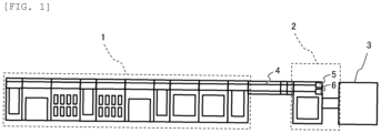
- FIG. 1 is a top view showing a configuration of a sample inspection system according to an embodiment of the invention.
- the sample inspection system includes a pretreatment device 1, a sample conveying device 2, an analyzer 3, and a conveyance line 4.
- the pretreatment device 1 performs pretreatment on a sample before an analysis process in the analyzer 3. Specifically, after a sample container accommodating a sample is loaded by an operator, processes such as centrifugation, plug opening, and dispensing are performed according to a request item.
- the pretreatment device 1 and the sample conveying device 2 include the conveyance line 4, and the sample subjected to the pretreatment is conveyed to the sample conveying device 2 by the conveyance line 4 together with a sample holder that supports the sample container.
- the sample conveying device 2 transfers the sample holder conveyed from the pretreatment device 1 to the different conveyance line 4 and conveys the sample holder to the analyzer 3, and includes a sample holder lifting mechanism 5 and a sample holder lowering mechanism 6 as a sample lifting and lowering mechanism.
- the sample conveying device 2 includes a first conveyance line and a second conveyance line provided above or below the first conveyance line. For example, the sample conveying device 2 lifts and lowers the carried-in sample holder from the first conveyance line by the sample lifting and lowering mechanism, and then carries out the sample holder from the second conveyance line to the analyzer 3.
- the analyzer 3 analyzes the sample in the sample container supported by the conveyed sample holder.
- the sample lifting and lowering mechanism is the sample holder lifting mechanism 5
- a case where the sample lifting and lowering mechanism is the sample holder lowering mechanism 6 will be described in Embodiment 2.
- the first conveyance line is a lower conveyance line 4a provided below
- the second conveyance line is an upper conveyance line 4b provided above.
- the first conveyance line is the upper conveyance line 4b provided above
- the second conveyance line is the lower conveyance line 4a provided below.
- the sample holder lifting mechanism 5 and the sample holder lowering mechanism 6 may be mounted not only on the sample conveying device 2 but also on other modules such as the pretreatment device 1.
- Embodiment 1 relates to the sample conveying device including the sample holder lifting mechanism 5, and will be described below with reference to FIGS. 2 to 10 .
- the sample conveying device 2 includes the lower conveyance line 4a (first conveyance line), the upper conveyance line 4b (second conveyance line), and the sample holder lifting mechanism 5.
- the lower conveyance line 4a conveys a sample holder 10 in a direction (leftward in the drawings) approaching the sample holder lifting mechanism 5, and carries in the sample holder 10 to the sample holder lifting mechanism 5 at an end portion of the lower conveyance line 4a.
- the upper conveyance line 4b carries out the sample holder 10 from the sample holder lifting mechanism 5 at an end portion of the upper conveyance line 4b, and conveys the sample holder 10 in a direction (rightward in the drawings) away from the sample holder lifting mechanism 5.
- the sample holder lifting mechanism 5 is a delivery mechanism of the sample holder 10 that is provided adjacent to each conveyance line, that lifts the carried-in sample holder 10 from the lower conveyance line 4a, and that carries out the sample holder 10 to the upper conveyance line 4b.
- the sample holder lifting mechanism 5 includes a sample holder loading unit 11, a following base 15, a power supply unit, a lifting and lowering rail 22, a drive base 26, a lifting and lowering spring 33 (first elastic body), a lower stopper 23, an upper stopper 24, an initial position detection sensor 30, and a carry-out position detection sensor 31.
- the sample holder loading unit 11 includes a loading surface 111, a holder stopper 112, a loading guide 113, a loading base 114, a rotary spring first attachment portion 18, and a holder detection sensor 37.
- the loading surface 111 is a surface on which the sample holder 10 is loaded.
- the holder stopper 112 is a stopper that prevents the sample holder 10 from falling and tipping over in a radial direction of a rotation trajectory of the sample holder 10.
- the loading guide 113 is a guide that prevents the sample holder 10 from falling and tipping over in an axial direction of the rotation trajectory of the sample holder 10.
- the loading base 114 is a base that supports the loading surface 111 from below.
- the rotary spring first attachment portion 18 is a member for attaching one end of a rotary spring 19 to the loading base 114.
- the holder detection sensor 37 is a sensor that detects presence or absence of the sample holder 10 on the sample holder loading unit 11.
- the sample holder loading unit 11 having the configuration as described above is coupled to the following base 15 by a rotary shaft 116 in a horizontal direction, and is rotatable around the rotary shaft 116.
- the sample holder loading unit 11 is inclined so as to rise toward the lower conveyance line 4a, so that the sample holder 10 can be received from the lower conveyance line 4a when the sample holder 10 is carried in. Accordingly, the sample holder 10 is less likely to fall even during the lifting of the sample holder loading unit 11.
- the following base 15 includes a following block 21, a support pole 32, a rotary spring second attachment portion 17, and a rotary stopper 20.
- the following block 21 is a block for connecting the following base 15 to the lifting and lowering rail 22 to be described later and guiding lifting and lowering operations of the following base 15.
- the support pole 32 extends downward and penetrates a support pole guide 38 of a drive block 25 to be described later.
- the rotary spring second attachment portion 17 is a member for attaching the other end of the rotary spring 19 to the following block 21.
- the rotary spring 19 (second elastic body) applies a force for rotating the sample holder loading unit 11 counterclockwise in the drawings by connecting the rotary spring first attachment portion 18 and the rotary spring second attachment portion 17.
- the rotary stopper 20 is a stopper for limiting a rotation range of the sample holder loading unit 11. Except when the sample holder 10 is carried out, a lower surface of the loading base 114 is in contact with the rotary stopper 20, and the sample holder loading unit 11 is maintained in an inclined state.
- the power supply unit includes a lifting and lowering motor 29 as a drive source and a lifting and lowering belt 28 as a movable body that extends vertically and that lifts and lowers by the lifting and lowering motor 29.
- the lifting and lowering rail 22 is a rail extending vertically in parallel with the lifting and lowering belt 28, and is connected to the above-described following block 21 and the drive block 25 to be described later.
- the drive base 26 includes the drive block 25, a belt holding tool 27, the support pole guide 38, a bush 34, a retaining ring 35, and a contactor 36.
- the drive block 25 is a block for connecting the drive base 26 to the lifting and lowering rail 22 and guiding lifting and lowering operations of the drive base 26.
- the belt holding tool 27 fixes the drive base 26 to the lifting and lowering belt 28. Accordingly, the drive base 26 can lift and lower integrally with the lifting and lowering belt 28 while being guided by the lifting and lowering rail 22.
- the support pole guide 38 extends toward a front of each drawing, and has a through hole (not shown) formed therein.
- the through hole has a size that allows the support pole 32 to pass therethrough but does not allow the lifting and lowering spring 33 to be described later to pass therethrough.
- the bush 34 is fixed to a predetermined position in a vicinity of a lower end of the support pole 32, and has a shape larger than that of the through hole. Therefore, when a distance from the drive base 26 to the following base 15 reaches a predetermined distance, an upper surface of the bush 34 is in contact with a lower surface of the support pole guide 38, and the distance is restricted from exceeding the predetermined distance.
- the retaining ring 35 serves to fix the bush 34 to the support pole 32.
- the contactor 36 is a portion that extends upward from the drive base 26 and that comes into contact with the lower surface of the loading base 114 of the sample holder loading unit 11.
- the lifting and lowering spring 33 is provided between an upper surface of the support pole guide 38 and a lower surface of the following base 15 so as to be inserted in an upper-lower direction with respect to an outer diameter side of the support pole 32, and connects the drive base 26 and the following base 15.
- the lifting and lowering spring 33 has a free length and does not generate an elastic force for pushing up the following base 15, and the lower surface of the following base 15 comes into contact with the lower stopper 23 to be described later, so that a load of the following base 15 is supported by the lower stopper 23.
- the lower stopper 23 (carry-in stopper) is a stopper that is provided at a predetermined height and restricts the lifting and lowering of the following base 15 when the sample holder 10 is carried in.
- the upper stopper 24 (carry-out stopper) is a stopper that is provided at a predetermined height above the lower stopper 23 and restricts the lifting and lowering of the following base 15 when the sample holder 10 is carried out.
- the initial position detection sensor 30 is a sensor for detecting that the drive base 26 is at the initial position, that is, the drive base 26 is at a lowest position as shown in FIGS. 2 and 3 , and that the drive base 26 is in a state where the carrying-in of the sample holder 10 can be started.
- the carry-out position detection sensor 31 is a sensor for detecting that the drive base 26 is at a carry-out position, that is, the drive base 26 is at a highest position as shown in FIGS. 6 and 7 , and that the drive base 26 is in a state where the carrying-out of the sample holder 10 can be completed.
- FIGS. 2 to 6 show a process in which the drive base 26 lifts after the sample holder loading unit 11 loads the sample holder 10
- FIGS. 7 to 10 show a process in which the drive base 26 lowers in a state where the sample holder loading unit 11 is empty.
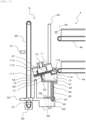
- FIG. 2 is a side view showing a state before the sample holder 10 is carried in in a sample conveying device according to Embodiment 1.
- the drive base 26 is at the initial position, and thus the initial position detection sensor 30 is turned on. Since the sample holder 10 is not yet carried in to the sample holder loading unit 11, the holder detection sensor 37 is turned off. The carry-out position detection sensor 31 is turned off.
- FIG. 3 is a side view showing a state immediately after the sample holder 10 is carried in in the sample conveying device according to Embodiment 1.
- the sample holder 10 conveyed by the lower conveyance line 4a is placed on the rotary shaft 116 and the loading surface 111, the sample holder 10 slides on the loading surface 111 leftward in the drawing due to an inclination of the sample holder loading unit 11.
- the sliding sample holder 10 comes into contact with the holder stopper 112 and stops. At this time, the holder detection sensor 37 is turned on.
- FIG. 4 is a side view showing a state immediately after the drive base 26 lifts and the contactor 36 is in contact with the loading base 114 in the sample conveying device according to Embodiment 1.
- the lifting and lowering motor 29 rotates counterclockwise from the state shown in FIG. 3 , the drive base 26 is lifted together with the lifting and lowering belt 28. At this time, the initial position detection sensor 30 is turned off.
- the drive base 26 lifts a relative distance between the drive base 26 and the following base 15 decreases, and thus the lifting and lowering spring 33 contracts and the contactor 36 comes into contact with the lower surface of the loading base 114.
- FIG. 5 is a side view showing a state immediately after the drive base 26 further lifts and the following base 15 is in contact with the upper stopper 24 in the sample conveying device according to Embodiment 1.
- the lifting and lowering motor 29 further rotates counterclockwise from the state shown in FIG. 4 , the drive base 26 further lifts together with the lifting and lowering belt 28.
- the loading base 114 is pushed up by the contactor 36 while the following base 15 is pushed up by the elastic force of the lifting and lowering spring 33, so that the sample holder loading unit 11 also lifts.
- the sample holder loading unit 11 Since the elastic force of the lifting and lowering spring 33 is set to be smaller than an elastic force of the rotary spring 19, the sample holder loading unit 11 is less likely to rotate during a lifting operation of the following base 15, so that the inclined state is maintained.
- the following base 15 lifts and is in contact with the upper stopper 24 at a predetermined height, the following base 15 is stopped by being restricted from further lifting, and enters the state shown in FIG. 5 .
- FIG. 6 is a side view showing a state immediately after the drive base 26 further lifts and reaches the carry-out position in the sample conveying device according to Embodiment 1.
- the lifting and lowering motor 29 further rotates counterclockwise from the state shown in FIG. 5 , the drive base 26 further lifts together with the lifting and lowering belt 28. In this manner, even when the drive base 26 further lifts after the following base 15 is in contact with the upper stopper 24, the pushing-up performed by the contactor 36 of the loading base 114 is continued. Then, as shown in FIG.
- the lifting and lowering spring 33 contracts as the drive base 26 lifts while the heights of the following base 15 and the rotary shaft 116 remain unchanged, and the rotary spring 19 expands, so that the sample holder loading unit 11 rotates clockwise around the rotary shaft 116.
- the carry-out position detection sensor 31 is turned on.
- FIG. 7 is a side view showing a state immediately after the sample holder 10 is carried out in the sample conveying device according to Embodiment 1.
- the sample holder loading unit 11 rotates and enters an inclined state of descending toward the upper conveyance line 4b
- the sample holder 10 slides on the loading surface 111 rightward in the drawing and is carried out to the upper conveyance line 4b as shown in FIG. 7 .
- the holder detection sensor 37 is turned off.
- the sample holder lifting mechanism 5 causes the lifting and lowering motor 29 to rotate clockwise to lower the drive base 26 together with the lifting and lowering belt 28 in order to carry in the next sample holder 10.
- FIG. 8 is a side view showing a state immediately before the drive base 26 lowers and the following base 15 is separated from the upper stopper 24 in the sample conveying device according to Embodiment 1.
- the carry-out position detection sensor 31 is turned off. Further, as the drive base 26 lowers, the lifting and lowering spring 33 gradually returns from the contracted state, while the rotary spring 19 gradually returns from the expanded state, and thus the heights of the following base 15 and the rotary shaft 116 are maintained.
- FIG. 9 is a side view showing a state immediately after the drive base 26 further lowers and the following base 15 is in contact with the lower stopper 23 in the sample conveying device according to Embodiment 1.
- the following base 15 and the rotary shaft 116 also lower.
- the following base 15 lowers and is in contact with the lower stopper 23 at the predetermined height, the following base 15 is stopped by being restricted from further lowering, and enters the state shown in FIG. 9 .
- FIG. 10 is a side view showing a state where the drive base 26 further lowers and reaches the initial position in the sample conveying device according to Embodiment 1.
- the drive base 26 further lowers from the state shown in FIG. 9 , the relative distance between the drive base 26 and the following base 15 increases, and thus the contactor 36 is separated from the loading base 114 and the lifting and lowering spring 33 is expanded.
- the drive base 26 returns to the initial position, and the initial position detection sensor 30 is turned on.
- Embodiment 2 relates to the sample conveying device including the sample holder lowering mechanism 6, and will be described below with reference to FIGS. 11 to 19 .
- the sample conveying device 2 includes the upper conveyance line 4b (first conveyance line), the lower conveyance line 4a (second conveyance line), and the sample holder lowering mechanism 6.
- the upper conveyance line 4b conveys the sample holder 10 in a direction (leftward in the drawings) approaching the sample holder lowering mechanism 6, and carries in the sample holder 10 to the sample holder lowering mechanism 6 at the end portion of the upper conveyance line 4b.
- the lower conveyance line 4a carries out the sample holder 10 from the sample holder lowering mechanism 6 at the end portion of the lower conveyance line 4a, and conveys the sample holder 10 in a direction (rightward in the drawings) away from the sample holder lowering mechanism 6.
- the sample holder lowering mechanism 6 is a delivery mechanism of the sample holder 10 that is provided adjacent to each conveyance line, that lowers the carried-in sample holder 10 from the upper conveyance line 4b, and that carries out the sample holder 10 to the lower conveyance line 4a.
- the sample holder lowering mechanism 6 includes the sample holder loading unit 11, the following base 15, the power supply unit, the lifting and lowering rail 22, the drive base 26, the lifting and lowering spring 33 (first elastic body), the lower stopper 23, the upper stopper 24, the initial position detection sensor 30, and the carry-out position detection sensor 31.
- the configuration of the sample holder lowering mechanism 6 is basically the same as that of the sample holder lifting mechanism 5 according to Embodiment 1, and thus only different points will be described here.
- the upper stopper 24 serves as a carry-in stopper
- the lower stopper 23 serves as a carry-out stopper.
- the initial position detection sensor 30 is located above the carry-out position detection sensor 31.
- the contactor 36 according to the present embodiment extends downward from the drive base 26 and is brought into contact with an upper surface of a portion extending from the sample holder loading unit 11 rightward in the drawings.
- a tension spring is used as the lifting and lowering spring 33.
- the support pole 32, the support pole guide 38, the bush 34, and the retaining ring 35 that are provided in the sample holder lifting mechanism 5 according to Embodiment 1 are not provided in the sample holder lowering mechanism 6 according to the present embodiment.
- FIGS. 11 to 15 show a process in which the drive base 26 lowers after the sample holder loading unit 11 loads the sample holder 10
- FIGS. 16 to 19 show a process in which the drive base 26 lifts in the state where the sample holder loading unit 11 is empty.
- FIG. 12 is a side view showing a state immediately after the sample holder 10 is carried in in the sample conveying device according to Embodiment 2.
- the sample holder 10 conveyed by the upper conveyance line 4b is placed on the rotary shaft 116 and the loading surface 111, the sample holder 10 slides on the loading surface 111 leftward in the drawing due to an inclination of the sample holder loading unit 11.
- the sliding sample holder 10 comes into contact with the holder stopper 112 and stops. At this time, the holder detection sensor 37 is turned on.
- FIG. 13 is a side view showing a state immediately after the drive base 26 lowers and the contactor 36 is in contact with the sample holder loading unit 11 in the sample conveying device according to Embodiment 2.
- the lifting and lowering motor 29 rotates clockwise from the state shown in FIG. 12 , the drive base 26 lowers together with the lifting and lowering belt 28. At this time, the initial position detection sensor 30 is turned off.
- the drive base 26 lowers, the relative distance between the drive base 26 and the following base 15 decreases, and thus the lifting and lowering spring 33 contracts and the contactor 36 comes into contact with the upper surface of the sample holder loading unit 11.
- FIG. 14 is a side view showing a state immediately after the drive base 26 further lowers and the following base 15 is in contact with the lower stopper 23 in the sample conveying device according to Embodiment 2.
- the lifting and lowering motor 29 further rotates clockwise from the state shown in FIG. 13 , the drive base 26 further lowers together with the lifting and lowering belt 28.
- the loading base 114 is pushed down by the contactor 36 while the following base 15 is pushed down by the elastic force of the lifting and lowering spring 33, and thus the sample holder loading unit 11 also lowers.
- the sample holder loading unit 11 Since the elastic force of the lifting and lowering spring 33 is set to be smaller than the elastic force of the rotary spring 19, the sample holder loading unit 11 is less likely to rotate during the lowering operation of the following base 15, and the inclined state is maintained.
- the following base 15 lowers and is in contact with the lower stopper 23 at the predetermined height, the following base 15 is stopped by being restricted from further lowering, and enters the state shown in FIG. 14 .
- FIG. 15 is a side view showing a state immediately after the drive base 26 further lowers and reaches the carry-out position in the sample conveying device according to Embodiment 2.
- the lifting and lowering motor 29 further rotates clockwise from the state shown in FIG. 14 , the drive base 26 further lowers together with the lifting and lowering belt 28.
- FIG. 16 is a side view showing a state immediately after the sample holder 10 is carried out in the sample conveying device according to Embodiment 2.
- the sample holder loading unit 11 rotates and enters an inclined state of descending toward the lower conveyance line 4a
- the sample holder 10 slides on the loading surface 111 rightward in the drawing and is carried out to the lower conveyance line 4a as shown in FIG. 16 .
- the holder detection sensor 37 is turned off.
- the sample holder lowering mechanism 6 causes the lifting and lowering motor 29 to rotate counterclockwise to lift the drive base 26 together with the lifting and lowering belt 28 in order to carry in the next sample holder 10.
- FIG. 17 is a side view showing a state immediately before the drive base 26 lifts and the following base 15 is separated from the lower stopper 23 in the sample conveying device according to Embodiment 2.
- the carry-out position detection sensor 31 is turned off. Further, as the drive base 26 lifts, the lifting and lowering spring 33 gradually returns from the contracted state, and the rotary spring 19 gradually returns from the expanded state, and thus the heights of the following base 15 and the rotary shaft 116 are maintained.
- FIG. 18 is a side view showing a state immediately after the drive base 26 further lifts and the following base 15 is in contact with the upper stopper 24 in the sample conveying device according to Embodiment 2.
- the drive base 26 further lifts from the state shown in FIG. 17
- the following base 15 and the rotary shaft 116 also lift.
- the following base 15 lifts and is in contact with the upper stopper 24 at the predetermined height
- the following base 15 is stopped by being restricted from further lifting, and enters the state shown in FIG. 18 .
- FIG. 19 is a side view showing a state where the drive base 26 further lifts to reach the initial position in the sample conveying device according to Embodiment 2.
- the drive base 26 further lifts from the state shown in FIG. 18 , the relative distance between the drive base 26 and the following base 15 increases, and thus the contactor 36 is separated from the sample holder loading unit 11 and the lifting and lowering spring 33 is expanded.
- the drive base 26 returns to the initial position, and the initial position detection sensor 30 is turned on.
- the sample holder lowering mechanism 6 when the drive base 26 lowers integrally with the rotation of the lifting and lowering motor 29, the following base 15 supporting the sample holder loading unit 11 lowers in conjunction with the drive base 26. After an operation of lowering the rotary shaft 116 together with the following base 15 is completed, the operation of rotating the sample holder loading unit 11 around the rotary shaft 116 is started. Accordingly, when the sample holder 10 is carried out by the rotation of the sample holder loading unit 11, a positional deviation between a start end of the lower conveyance line 4a which is the carry-out destination and a lower conveyance line 4a side end of the loading surface 111 on the sample holder loading unit 11 is reduced.
Landscapes
- Physics & Mathematics (AREA)
- Health & Medical Sciences (AREA)
- Life Sciences & Earth Sciences (AREA)
- Chemical & Material Sciences (AREA)
- Analytical Chemistry (AREA)
- Biochemistry (AREA)
- General Health & Medical Sciences (AREA)
- General Physics & Mathematics (AREA)
- Immunology (AREA)
- Pathology (AREA)
- Engineering & Computer Science (AREA)
- Mechanical Engineering (AREA)
- Automatic Analysis And Handling Materials Therefor (AREA)
- Analysing Materials By The Use Of Radiation (AREA)
- Sampling And Sample Adjustment (AREA)
Abstract
Description
- The present invention relates to a sample lifting and lowering mechanism and a sample conveying device.
- In a system for inspecting a sample, a plurality of conveyance lines for conveying the sample are provided in addition to an analyzer. In particular, when the conveyance lines are provided vertically, a mechanism for lifting and lowering the sample from one conveyance line to the other conveyance line is required.
- Here, for example,
PTL 1 is known as a technique for eliminating a need for a drive source dedicated to delivery when an article is carried in or carried out between a conveyance mechanism and a conveyance line unless a conveyance target is limited to the sample.PTL 1 discloses that, when a loading unit (lifting and lowering roller base) of an article (pallet) lifts and lowers, and comes into contact with a stopper at a predetermined height, the loading unit rotates around a fulcrum provided on a bottom surface of the loading unit as a shaft, and the article is carried-out by an own weight thereof due to an inclination of the loading unit. - PTL 1:
JPH04-260523A - In the technique disclosed in
PTL 1, when the loading unit rotates in order to carry out the article, the fulcrum serving as a rotary shaft of the loading unit lifts or lowers. That is, since the rotation operation of the loading unit and a vertical movement operation of the rotary shaft proceed in parallel, there is a possibility that a positional relationship between the loading unit and the (carry-out destination) conveyance line is deviated depending on a timing when the article is carried out. In particular, when the conveyance target is a relatively small sample holder, there is a possibility that the sample holder may tip over even with a slight positional deviation. - An object of the invention is to provide a sample lifting and lowering mechanism and a sample conveying device that are capable of carrying out a sample holder without tipping over the sample holder.
- In order to achieve said purpose, a sample lifting and lowering mechanism according to the invention includes a sample holder loading unit configured to load a sample holder and to be rotatable around a rotary shaft. The sample lifting and lowering mechanism lifts, lowers, and carries-out the carried-in sample holder to the sample holder loading unit, and an operation in which the sample holder loading unit rotates around the rotary shaft is started after an operation in which the rotary shaft lifts or lowers is completed. In addition, a sample conveying device according to the invention includes: a first conveyance line configured to convey a sample holder; a second conveyance line provided above or below the first conveyance line and configured to convey the sample holder; and the sample lifting and lowering mechanism configured to, when the sample holder conveyed by the first conveyance line is carried-in, lift and lower the sample holder and carry-out the sample holder to the second conveyance line.
- According to the invention, it is possible to provide a sample lifting and lowering mechanism and a sample conveying device that capable of carrying out a sample holder without tipping over the sample holder.
-
- [
FIG. 1] FIG. 1 is a top view showing a configuration of a sample inspection system according to an embodiment of the invention. - [
FIG. 2] FIG. 2 is a side view showing a state before a sample holder is carried in in a sample conveying device according toEmbodiment 1. - [
FIG. 3] FIG. 3 is a side view showing a state immediately after the sample holder is carried in in the sample conveying device according toEmbodiment 1. - [
FIG. 4] FIG. 4 is a side view showing a state immediately after a drive base lifts and a contactor is in contact with a loading base in the sample conveying device according toEmbodiment 1. - [
FIG. 5] FIG. 5 is a side view showing a state immediately after the drive base further lifts and the following base is in contact with an upper stopper in the sample conveying device according toEmbodiment 1. - [
FIG. 6] FIG. 6 is a side view showing a state immediately after the drive base further lifts and reaches a carry-out position in the sample conveying device according toEmbodiment 1. - [
FIG. 7] FIG. 7 is a side view showing a state immediately after the sample holder is carried out in the sample conveying device according toEmbodiment 1. - [
FIG. 8] FIG. 8 is a side view showing a state immediately before the drive base lowers and the following base is separated from the upper stopper in the sample conveying device according toEmbodiment 1. - [
FIG. 9] FIG. 9 is a side view showing a state immediately after the drive base further lowers and the following base is in contact with a lower stopper in the sample conveying device according toEmbodiment 1. - [
FIG. 10] FIG. 10 is a side view showing a state where the drive base further lowers and reaches an initial position in the sample conveying device according toEmbodiment 1. - [
FIG. 11] FIG. 11 is a side view showing a state before a sample holder is carried in in a sample conveying device according toEmbodiment 2. - [
FIG. 12] FIG. 12 is a side view showing a state immediately after the sample holder is carried in in the sample conveying device according toEmbodiment 2. - [
FIG. 13] FIG. 13 is a side view showing a state immediately after the drive base lowers and a contactor is in contact with a sample holder loading unit in the sample conveying device according toEmbodiment 2. - [
FIG. 14] FIG. 14 is a side view showing a state immediately after the drive base further lowers and the following base is in contact with a lower stopper in the sample conveying device according toEmbodiment 2. - [
FIG. 15] FIG. 15 is a side view showing a state immediately after the drive base further lowers and reaches a carry-out position in the sample conveying device according toEmbodiment 2. - [
FIG. 16] FIG. 16 is a side view showing a state immediately after the sample holder is carried out in the sample conveying device according toEmbodiment 2. - [
FIG. 17] FIG. 17 is a side view showing a state immediately before the drive base lifts and the following base is separated from the lower stopper in the sample conveying device according toEmbodiment 2. - [
FIG. 18] FIG. 18 is a side view showing a state immediately after the drive base further lifts and the following base is in contact with an upper stopper in the sample conveying device according toEmbodiment 2. - [
FIG. 19] FIG. 19 is a side view showing a state where the drive base further lifts and reaches an initial position in the sample conveying device according toEmbodiment 2. - Hereinafter, embodiments of the invention will be described with reference to the drawings.
-
FIG. 1 is a top view showing a configuration of a sample inspection system according to an embodiment of the invention. As shown inFIG. 1 , the sample inspection system according to the present embodiment includes apretreatment device 1, asample conveying device 2, ananalyzer 3, and aconveyance line 4. Thepretreatment device 1 performs pretreatment on a sample before an analysis process in theanalyzer 3. Specifically, after a sample container accommodating a sample is loaded by an operator, processes such as centrifugation, plug opening, and dispensing are performed according to a request item. Thepretreatment device 1 and thesample conveying device 2 include theconveyance line 4, and the sample subjected to the pretreatment is conveyed to thesample conveying device 2 by theconveyance line 4 together with a sample holder that supports the sample container. - The
sample conveying device 2 transfers the sample holder conveyed from thepretreatment device 1 to thedifferent conveyance line 4 and conveys the sample holder to theanalyzer 3, and includes a sampleholder lifting mechanism 5 and a sampleholder lowering mechanism 6 as a sample lifting and lowering mechanism. In addition, as described later, thesample conveying device 2 includes a first conveyance line and a second conveyance line provided above or below the first conveyance line. For example, thesample conveying device 2 lifts and lowers the carried-in sample holder from the first conveyance line by the sample lifting and lowering mechanism, and then carries out the sample holder from the second conveyance line to theanalyzer 3. Theanalyzer 3 analyzes the sample in the sample container supported by the conveyed sample holder. - Hereinafter, a case where the sample lifting and lowering mechanism is the sample
holder lifting mechanism 5 will be described inEmbodiment 1, and a case where the sample lifting and lowering mechanism is the sampleholder lowering mechanism 6 will be described inEmbodiment 2. Here, in the case ofEmbodiment 1, the first conveyance line is alower conveyance line 4a provided below, and the second conveyance line is anupper conveyance line 4b provided above. On the other hand, in the case ofEmbodiment 2, the first conveyance line is theupper conveyance line 4b provided above, and the second conveyance line is thelower conveyance line 4a provided below. The sampleholder lifting mechanism 5 and the sampleholder lowering mechanism 6 may be mounted not only on thesample conveying device 2 but also on other modules such as thepretreatment device 1. -
Embodiment 1 relates to the sample conveying device including the sampleholder lifting mechanism 5, and will be described below with reference toFIGS. 2 to 10 . - As shown in
FIGS. 2 to 10 , thesample conveying device 2 according to the present embodiment includes thelower conveyance line 4a (first conveyance line), theupper conveyance line 4b (second conveyance line), and the sampleholder lifting mechanism 5. Thelower conveyance line 4a conveys asample holder 10 in a direction (leftward in the drawings) approaching the sampleholder lifting mechanism 5, and carries in thesample holder 10 to the sampleholder lifting mechanism 5 at an end portion of thelower conveyance line 4a. On the other hand, theupper conveyance line 4b carries out thesample holder 10 from the sampleholder lifting mechanism 5 at an end portion of theupper conveyance line 4b, and conveys thesample holder 10 in a direction (rightward in the drawings) away from the sampleholder lifting mechanism 5. - Next, a configuration of the sample
holder lifting mechanism 5 will be described. The sampleholder lifting mechanism 5 is a delivery mechanism of thesample holder 10 that is provided adjacent to each conveyance line, that lifts the carried-insample holder 10 from thelower conveyance line 4a, and that carries out thesample holder 10 to theupper conveyance line 4b. The sampleholder lifting mechanism 5 includes a sampleholder loading unit 11, a followingbase 15, a power supply unit, a lifting and loweringrail 22, adrive base 26, a lifting and lowering spring 33 (first elastic body), alower stopper 23, anupper stopper 24, an initialposition detection sensor 30, and a carry-outposition detection sensor 31. - First, the sample
holder loading unit 11 includes aloading surface 111, aholder stopper 112, aloading guide 113, aloading base 114, a rotary springfirst attachment portion 18, and aholder detection sensor 37. Theloading surface 111 is a surface on which thesample holder 10 is loaded. Theholder stopper 112 is a stopper that prevents thesample holder 10 from falling and tipping over in a radial direction of a rotation trajectory of thesample holder 10. Theloading guide 113 is a guide that prevents thesample holder 10 from falling and tipping over in an axial direction of the rotation trajectory of thesample holder 10. Theloading base 114 is a base that supports theloading surface 111 from below. The rotary springfirst attachment portion 18 is a member for attaching one end of arotary spring 19 to theloading base 114. Theholder detection sensor 37 is a sensor that detects presence or absence of thesample holder 10 on the sampleholder loading unit 11. - The sample
holder loading unit 11 having the configuration as described above is coupled to the followingbase 15 by arotary shaft 116 in a horizontal direction, and is rotatable around therotary shaft 116. The sampleholder loading unit 11 is inclined so as to rise toward thelower conveyance line 4a, so that thesample holder 10 can be received from thelower conveyance line 4a when thesample holder 10 is carried in. Accordingly, thesample holder 10 is less likely to fall even during the lifting of the sampleholder loading unit 11. - The following
base 15 includes a followingblock 21, asupport pole 32, a rotary springsecond attachment portion 17, and arotary stopper 20. The followingblock 21 is a block for connecting the followingbase 15 to the lifting and loweringrail 22 to be described later and guiding lifting and lowering operations of the followingbase 15. Thesupport pole 32 extends downward and penetrates asupport pole guide 38 of adrive block 25 to be described later. The rotary springsecond attachment portion 17 is a member for attaching the other end of therotary spring 19 to the followingblock 21. The rotary spring 19 (second elastic body) applies a force for rotating the sampleholder loading unit 11 counterclockwise in the drawings by connecting the rotary springfirst attachment portion 18 and the rotary springsecond attachment portion 17. Therotary stopper 20 is a stopper for limiting a rotation range of the sampleholder loading unit 11. Except when thesample holder 10 is carried out, a lower surface of theloading base 114 is in contact with therotary stopper 20, and the sampleholder loading unit 11 is maintained in an inclined state. - The power supply unit includes a lifting and lowering
motor 29 as a drive source and a lifting and loweringbelt 28 as a movable body that extends vertically and that lifts and lowers by the lifting and loweringmotor 29. - The lifting and lowering
rail 22 is a rail extending vertically in parallel with the lifting and loweringbelt 28, and is connected to the above-described followingblock 21 and thedrive block 25 to be described later. - The
drive base 26 includes thedrive block 25, abelt holding tool 27, thesupport pole guide 38, abush 34, a retainingring 35, and acontactor 36. Thedrive block 25 is a block for connecting thedrive base 26 to the lifting and loweringrail 22 and guiding lifting and lowering operations of thedrive base 26. Thebelt holding tool 27 fixes thedrive base 26 to the lifting and loweringbelt 28. Accordingly, thedrive base 26 can lift and lower integrally with the lifting and loweringbelt 28 while being guided by the lifting and loweringrail 22. Thesupport pole guide 38 extends toward a front of each drawing, and has a through hole (not shown) formed therein. The through hole has a size that allows thesupport pole 32 to pass therethrough but does not allow the lifting and loweringspring 33 to be described later to pass therethrough. Thebush 34 is fixed to a predetermined position in a vicinity of a lower end of thesupport pole 32, and has a shape larger than that of the through hole. Therefore, when a distance from thedrive base 26 to the followingbase 15 reaches a predetermined distance, an upper surface of thebush 34 is in contact with a lower surface of thesupport pole guide 38, and the distance is restricted from exceeding the predetermined distance. The retainingring 35 serves to fix thebush 34 to thesupport pole 32. Thecontactor 36 is a portion that extends upward from thedrive base 26 and that comes into contact with the lower surface of theloading base 114 of the sampleholder loading unit 11. - The lifting and lowering
spring 33 is provided between an upper surface of thesupport pole guide 38 and a lower surface of the followingbase 15 so as to be inserted in an upper-lower direction with respect to an outer diameter side of thesupport pole 32, and connects thedrive base 26 and the followingbase 15. In a state (state shown inFIGS. 2 and3 ) where thedrive base 26 is at an initial position, the lifting and loweringspring 33 has a free length and does not generate an elastic force for pushing up the followingbase 15, and the lower surface of the followingbase 15 comes into contact with thelower stopper 23 to be described later, so that a load of the followingbase 15 is supported by thelower stopper 23. - The lower stopper 23 (carry-in stopper) is a stopper that is provided at a predetermined height and restricts the lifting and lowering of the following
base 15 when thesample holder 10 is carried in. - The upper stopper 24 (carry-out stopper) is a stopper that is provided at a predetermined height above the
lower stopper 23 and restricts the lifting and lowering of the followingbase 15 when thesample holder 10 is carried out. - The initial
position detection sensor 30 is a sensor for detecting that thedrive base 26 is at the initial position, that is, thedrive base 26 is at a lowest position as shown inFIGS. 2 and3 , and that thedrive base 26 is in a state where the carrying-in of thesample holder 10 can be started. - The carry-out
position detection sensor 31 is a sensor for detecting that thedrive base 26 is at a carry-out position, that is, thedrive base 26 is at a highest position as shown inFIGS. 6 and7 , and that thedrive base 26 is in a state where the carrying-out of thesample holder 10 can be completed. - Next, operations of the sample
holder lifting mechanism 5 will be described.FIGS. 2 to 6 show a process in which thedrive base 26 lifts after the sampleholder loading unit 11 loads thesample holder 10, andFIGS. 7 to 10 show a process in which thedrive base 26 lowers in a state where the sampleholder loading unit 11 is empty. -
FIG. 2 is a side view showing a state before thesample holder 10 is carried in in a sample conveying device according toEmbodiment 1. At this time, thedrive base 26 is at the initial position, and thus the initialposition detection sensor 30 is turned on. Since thesample holder 10 is not yet carried in to the sampleholder loading unit 11, theholder detection sensor 37 is turned off. The carry-outposition detection sensor 31 is turned off. -
FIG. 3 is a side view showing a state immediately after thesample holder 10 is carried in in the sample conveying device according toEmbodiment 1. When thesample holder 10 conveyed by thelower conveyance line 4a is placed on therotary shaft 116 and theloading surface 111, thesample holder 10 slides on theloading surface 111 leftward in the drawing due to an inclination of the sampleholder loading unit 11. The slidingsample holder 10 comes into contact with theholder stopper 112 and stops. At this time, theholder detection sensor 37 is turned on. -
FIG. 4 is a side view showing a state immediately after thedrive base 26 lifts and thecontactor 36 is in contact with theloading base 114 in the sample conveying device according toEmbodiment 1. When the lifting and loweringmotor 29 rotates counterclockwise from the state shown inFIG. 3 , thedrive base 26 is lifted together with the lifting and loweringbelt 28. At this time, the initialposition detection sensor 30 is turned off. When thedrive base 26 lifts, a relative distance between thedrive base 26 and the followingbase 15 decreases, and thus the lifting and loweringspring 33 contracts and thecontactor 36 comes into contact with the lower surface of theloading base 114. -
FIG. 5 is a side view showing a state immediately after thedrive base 26 further lifts and the followingbase 15 is in contact with theupper stopper 24 in the sample conveying device according toEmbodiment 1. When the lifting and loweringmotor 29 further rotates counterclockwise from the state shown inFIG. 4 , thedrive base 26 further lifts together with the lifting and loweringbelt 28. At this time, theloading base 114 is pushed up by thecontactor 36 while the followingbase 15 is pushed up by the elastic force of the lifting and loweringspring 33, so that the sampleholder loading unit 11 also lifts. Since the elastic force of the lifting and loweringspring 33 is set to be smaller than an elastic force of therotary spring 19, the sampleholder loading unit 11 is less likely to rotate during a lifting operation of the followingbase 15, so that the inclined state is maintained. When the followingbase 15 lifts and is in contact with theupper stopper 24 at a predetermined height, the followingbase 15 is stopped by being restricted from further lifting, and enters the state shown inFIG. 5 . -
FIG. 6 is a side view showing a state immediately after thedrive base 26 further lifts and reaches the carry-out position in the sample conveying device according toEmbodiment 1. When the lifting and loweringmotor 29 further rotates counterclockwise from the state shown inFIG. 5 , thedrive base 26 further lifts together with the lifting and loweringbelt 28. In this manner, even when thedrive base 26 further lifts after the followingbase 15 is in contact with theupper stopper 24, the pushing-up performed by thecontactor 36 of theloading base 114 is continued. Then, as shown inFIG. 6 , the lifting and loweringspring 33 contracts as thedrive base 26 lifts while the heights of the followingbase 15 and therotary shaft 116 remain unchanged, and therotary spring 19 expands, so that the sampleholder loading unit 11 rotates clockwise around therotary shaft 116. At this time, the carry-outposition detection sensor 31 is turned on. -
FIG. 7 is a side view showing a state immediately after thesample holder 10 is carried out in the sample conveying device according toEmbodiment 1. When the sampleholder loading unit 11 rotates and enters an inclined state of descending toward theupper conveyance line 4b, thesample holder 10 slides on theloading surface 111 rightward in the drawing and is carried out to theupper conveyance line 4b as shown inFIG. 7 . At this time, theholder detection sensor 37 is turned off. - When the carrying-out of the
sample holder 10 is completed, the sampleholder lifting mechanism 5 causes the lifting and loweringmotor 29 to rotate clockwise to lower thedrive base 26 together with the lifting and loweringbelt 28 in order to carry in thenext sample holder 10. -
FIG. 8 is a side view showing a state immediately before thedrive base 26 lowers and the followingbase 15 is separated from theupper stopper 24 in the sample conveying device according toEmbodiment 1. When thedrive base 26 starts to lower from the state shown inFIG. 7 , the carry-outposition detection sensor 31 is turned off. Further, as thedrive base 26 lowers, the lifting and loweringspring 33 gradually returns from the contracted state, while therotary spring 19 gradually returns from the expanded state, and thus the heights of the followingbase 15 and therotary shaft 116 are maintained. -
FIG. 9 is a side view showing a state immediately after thedrive base 26 further lowers and the followingbase 15 is in contact with thelower stopper 23 in the sample conveying device according toEmbodiment 1. When thedrive base 26 further lowers from the state shown inFIG. 8 , the followingbase 15 and therotary shaft 116 also lower. When the followingbase 15 lowers and is in contact with thelower stopper 23 at the predetermined height, the followingbase 15 is stopped by being restricted from further lowering, and enters the state shown inFIG. 9 . -
FIG. 10 is a side view showing a state where thedrive base 26 further lowers and reaches the initial position in the sample conveying device according toEmbodiment 1. When thedrive base 26 further lowers from the state shown inFIG. 9 , the relative distance between thedrive base 26 and the followingbase 15 increases, and thus thecontactor 36 is separated from theloading base 114 and the lifting and loweringspring 33 is expanded. Finally, as shown inFIG. 10 , thedrive base 26 returns to the initial position, and the initialposition detection sensor 30 is turned on. - As described above, in the sample
holder lifting mechanism 5 according to the present embodiment, when thedrive base 26 lifts integrally with the rotation of the lifting and loweringmotor 29, the followingbase 15 supporting the sampleholder loading unit 11 lifts in conjunction with thedrive base 26. After an operation of lifting therotary shaft 116 together with the followingbase 15 is completed, an operation of rotating the sampleholder loading unit 11 around therotary shaft 116 is started. Accordingly, when thesample holder 10 is carried out by the rotation of the sampleholder loading unit 11, a positional deviation between a start end of theupper conveyance line 4b which is a carry-out destination and anupper conveyance line 4b side end of theloading surface 111 on the sampleholder loading unit 11 is reduced. As a result, it is possible to prevent thesample holder 10 from tipping over during the carrying-out. In particular, since therotary shaft 116 is at an end portion on the loading surface 111 (on theupper conveyance line 4b side), a gap between theloading surface 111 and theupper conveyance line 4b during the carrying-out is further reduced. Accordingly, thesample holder 10 can pass from theloading surface 111 over therotary shaft 116 while sliding and smoothly reach theupper conveyance line 4b. -
Embodiment 2 relates to the sample conveying device including the sampleholder lowering mechanism 6, and will be described below with reference toFIGS. 11 to 19 . - As shown in
FIGS. 11 to 19 , thesample conveying device 2 according to the present embodiment includes theupper conveyance line 4b (first conveyance line), thelower conveyance line 4a (second conveyance line), and the sampleholder lowering mechanism 6. Theupper conveyance line 4b conveys thesample holder 10 in a direction (leftward in the drawings) approaching the sampleholder lowering mechanism 6, and carries in thesample holder 10 to the sampleholder lowering mechanism 6 at the end portion of theupper conveyance line 4b. On the other hand, thelower conveyance line 4a carries out thesample holder 10 from the sampleholder lowering mechanism 6 at the end portion of thelower conveyance line 4a, and conveys thesample holder 10 in a direction (rightward in the drawings) away from the sampleholder lowering mechanism 6. - Next, a configuration of the sample
holder lowering mechanism 6 will be described. The sampleholder lowering mechanism 6 is a delivery mechanism of thesample holder 10 that is provided adjacent to each conveyance line, that lowers the carried-insample holder 10 from theupper conveyance line 4b, and that carries out thesample holder 10 to thelower conveyance line 4a. Similarly to the sampleholder lifting mechanism 5 according toEmbodiment 1, the sampleholder lowering mechanism 6 includes the sampleholder loading unit 11, the followingbase 15, the power supply unit, the lifting and loweringrail 22, thedrive base 26, the lifting and lowering spring 33 (first elastic body), thelower stopper 23, theupper stopper 24, the initialposition detection sensor 30, and the carry-outposition detection sensor 31. The configuration of the sampleholder lowering mechanism 6 is basically the same as that of the sampleholder lifting mechanism 5 according toEmbodiment 1, and thus only different points will be described here. - In the present embodiment, the
upper stopper 24 serves as a carry-in stopper, and thelower stopper 23 serves as a carry-out stopper. In the present embodiment, the initialposition detection sensor 30 is located above the carry-outposition detection sensor 31. Further, thecontactor 36 according to the present embodiment extends downward from thedrive base 26 and is brought into contact with an upper surface of a portion extending from the sampleholder loading unit 11 rightward in the drawings. In the present embodiment, a tension spring is used as the lifting and loweringspring 33. Thesupport pole 32, thesupport pole guide 38, thebush 34, and the retainingring 35 that are provided in the sampleholder lifting mechanism 5 according toEmbodiment 1 are not provided in the sampleholder lowering mechanism 6 according to the present embodiment. - Next, operations of the sample
holder lowering mechanism 6 will be described.FIGS. 11 to 15 show a process in which thedrive base 26 lowers after the sampleholder loading unit 11 loads thesample holder 10, andFIGS. 16 to 19 show a process in which thedrive base 26 lifts in the state where the sampleholder loading unit 11 is empty. -
FIG. 11 is a side view showing a state before thesample holder 10 is carried in in the sample conveying device according toEmbodiment 2. At this time, thedrive base 26 is at the initial position, and thus the initialposition detection sensor 30 is turned on. Since thesample holder 10 is not yet carried in to the sampleholder loading unit 11, theholder detection sensor 37 is turned off. The carry-outposition detection sensor 31 is turned off. -
FIG. 12 is a side view showing a state immediately after thesample holder 10 is carried in in the sample conveying device according toEmbodiment 2. When thesample holder 10 conveyed by theupper conveyance line 4b is placed on therotary shaft 116 and theloading surface 111, thesample holder 10 slides on theloading surface 111 leftward in the drawing due to an inclination of the sampleholder loading unit 11. The slidingsample holder 10 comes into contact with theholder stopper 112 and stops. At this time, theholder detection sensor 37 is turned on. -
FIG. 13 is a side view showing a state immediately after thedrive base 26 lowers and thecontactor 36 is in contact with the sampleholder loading unit 11 in the sample conveying device according toEmbodiment 2. When the lifting and loweringmotor 29 rotates clockwise from the state shown inFIG. 12 , thedrive base 26 lowers together with the lifting and loweringbelt 28. At this time, the initialposition detection sensor 30 is turned off. When thedrive base 26 lowers, the relative distance between thedrive base 26 and the followingbase 15 decreases, and thus the lifting and loweringspring 33 contracts and thecontactor 36 comes into contact with the upper surface of the sampleholder loading unit 11. -
FIG. 14 is a side view showing a state immediately after thedrive base 26 further lowers and the followingbase 15 is in contact with thelower stopper 23 in the sample conveying device according toEmbodiment 2. When the lifting and loweringmotor 29 further rotates clockwise from the state shown inFIG. 13 , thedrive base 26 further lowers together with the lifting and loweringbelt 28. At this time, theloading base 114 is pushed down by thecontactor 36 while the followingbase 15 is pushed down by the elastic force of the lifting and loweringspring 33, and thus the sampleholder loading unit 11 also lowers. Since the elastic force of the lifting and loweringspring 33 is set to be smaller than the elastic force of therotary spring 19, the sampleholder loading unit 11 is less likely to rotate during the lowering operation of the followingbase 15, and the inclined state is maintained. When the followingbase 15 lowers and is in contact with thelower stopper 23 at the predetermined height, the followingbase 15 is stopped by being restricted from further lowering, and enters the state shown inFIG. 14 . -
FIG. 15 is a side view showing a state immediately after thedrive base 26 further lowers and reaches the carry-out position in the sample conveying device according toEmbodiment 2. When the lifting and loweringmotor 29 further rotates clockwise from the state shown inFIG. 14 , thedrive base 26 further lowers together with the lifting and loweringbelt 28. - In this manner, even when the
drive base 26 further lowers after the followingbase 15 is in contact with thelower stopper 23, the pushing-down performed by thecontactor 36 of the sampleholder loading unit 11 is continued. Then, as shown inFIG. 15 , the lifting and loweringspring 33 contracts as thedrive base 26 lowers while the heights of the followingbase 15 and therotary shaft 116 remain unchanged, and therotary spring 19 expands, so that the sampleholder loading unit 11 rotates clockwise around therotary shaft 116. At this time, the carry-outposition detection sensor 31 is turned on. -
FIG. 16 is a side view showing a state immediately after thesample holder 10 is carried out in the sample conveying device according toEmbodiment 2. When the sampleholder loading unit 11 rotates and enters an inclined state of descending toward thelower conveyance line 4a, thesample holder 10 slides on theloading surface 111 rightward in the drawing and is carried out to thelower conveyance line 4a as shown inFIG. 16 . At this time, theholder detection sensor 37 is turned off. - When the carrying-out of the
sample holder 10 is completed, the sampleholder lowering mechanism 6 causes the lifting and loweringmotor 29 to rotate counterclockwise to lift thedrive base 26 together with the lifting and loweringbelt 28 in order to carry in thenext sample holder 10. -
FIG. 17 is a side view showing a state immediately before thedrive base 26 lifts and the followingbase 15 is separated from thelower stopper 23 in the sample conveying device according toEmbodiment 2. When thedrive base 26 starts to lift from the state shown inFIG. 16 , the carry-outposition detection sensor 31 is turned off. Further, as thedrive base 26 lifts, the lifting and loweringspring 33 gradually returns from the contracted state, and therotary spring 19 gradually returns from the expanded state, and thus the heights of the followingbase 15 and therotary shaft 116 are maintained. -
FIG. 18 is a side view showing a state immediately after thedrive base 26 further lifts and the followingbase 15 is in contact with theupper stopper 24 in the sample conveying device according toEmbodiment 2. When thedrive base 26 further lifts from the state shown inFIG. 17 , the followingbase 15 and therotary shaft 116 also lift. When the followingbase 15 lifts and is in contact with theupper stopper 24 at the predetermined height, the followingbase 15 is stopped by being restricted from further lifting, and enters the state shown inFIG. 18 . -
FIG. 19 is a side view showing a state where thedrive base 26 further lifts to reach the initial position in the sample conveying device according toEmbodiment 2. When thedrive base 26 further lifts from the state shown inFIG. 18 , the relative distance between thedrive base 26 and the followingbase 15 increases, and thus thecontactor 36 is separated from the sampleholder loading unit 11 and the lifting and loweringspring 33 is expanded. Finally, as shown inFIG. 19 , thedrive base 26 returns to the initial position, and the initialposition detection sensor 30 is turned on. - As described above, in the sample
holder lowering mechanism 6 according to the present embodiment, when thedrive base 26 lowers integrally with the rotation of the lifting and loweringmotor 29, the followingbase 15 supporting the sampleholder loading unit 11 lowers in conjunction with thedrive base 26. After an operation of lowering therotary shaft 116 together with the followingbase 15 is completed, the operation of rotating the sampleholder loading unit 11 around therotary shaft 116 is started. Accordingly, when thesample holder 10 is carried out by the rotation of the sampleholder loading unit 11, a positional deviation between a start end of thelower conveyance line 4a which is the carry-out destination and alower conveyance line 4a side end of theloading surface 111 on the sampleholder loading unit 11 is reduced. As a result, it is possible to prevent thesample holder 10 from tipping over during the carrying-out. In particular, since therotary shaft 116 is at an end portion on the loading surface 111 (on thelower conveyance line 4a side), a gap between theloading surface 111 and thelower conveyance line 4a during the carrying-out is further reduced. Accordingly, thesample holder 10 can pass from theloading surface 111 over therotary shaft 116 while sliding, and smoothly reach thelower conveyance line 4a. -
- 1:
- pretreatment device
- 2:
- sample conveying device
- 3:
- analyzer
- 4:
- conveyance line
- 4a:
- lower conveyance line
- 4b:
- upper conveyance line
- 5:
- sample holder lifting mechanism
- 6:
- sample holder lowering mechanism
- 10:
- sample holder
- 11:
- sample holder loading unit
- 15:
- following base
- 17:
- rotary spring second attachment portion
- 18:
- rotary spring first attachment portion
- 19:
- rotary spring
- 20:
- rotary stopper
- 21:
- following block
- 22:
- lifting and lowering rail
- 23:
- lower stopper
- 24:
- upper stopper
- 25:
- drive block
- 26:
- drive base
- 27:
- belt holding tool
- 28:
- lifting and lowering belt
- 29:
- lifting and lowering motor
- 30:
- initial position detection sensor
- 31:
- carry-out position detection sensor
- 32:
- support pole
- 33:
- lifting and lowering spring
- 34:
- bush
- 35:
- retaining ring
- 36:
- contactor
- 37:
- holder detection sensor
- 38:
- support pole guide
- 111:
- loading surface
- 112:
- holder stopper
- 113:
- loading guide
- 114:
- loading base
- 116:
- rotary shaft
Claims (12)
- A sample lifting and lowering mechanism comprising:a sample holder loading unit configured to load a sample holder and to rotate around a rotary shaft, whereinthe sample lifting and lowering mechanism lifts, lowers, and carries out the carried-in sample holder to the sample holder loading unit, andan operation in which the sample holder loading unit rotates around the rotary shaft is started after an operation in which the rotary shaft lifts or lowers is completed.
- A sample lifting and lowering mechanism comprising:a power supply unit configured to lift and lower a vertically extending movable body by a drive source;a lifting and lowering rail vertically extending parallel to the movable body;a drive base fixed to the movable body and configured to lift and lower integrally with the movable body while being guided by the lifting and lowering rail;a following base configured to lift and lower while being guided by the lifting and lowering rail;a first elastic body connecting the drive base and the following base;a sample holder loading unit on which a sample holder is loaded;a rotary shaft in a horizontal direction rotatably coupling the sample holder loading unit to the following base;a contactor extending in an upper-lower direction from the drive base and configured to come into contact with the sample holder loading unit; anda carry-out stopper provided at a predetermined height and configured to restrict lifting and lowering of the following base when the sample holder is carried out, whereinwhen the drive base lifts and lowers,the sample holder loading unit also lifts and lowers by the contactor pushing up or down the sample holder loading unit while the following base is pushed up or down by an elastic force of the first elastic body before the following base is in contact with the carry-out stopper, andthe sample holder loading unit rotates around the rotary shaft by the contactor continuing to push up or down the sample holder loading unit while the lifting and lowering of the following base is restricted by the carry-out stopper after the following base is in contact with the carry-out stopper.
- The sample lifting and lowering mechanism according to claim 2, further comprising:a second elastic body connecting the following base and the sample holder loading unit, whereinafter the following base is in contact with the carry-out stopper, the first elastic body contracts and the second elastic body expands as the drive base lifts and lowers.
- The sample lifting and lowering mechanism according to claim 3, wherein
the first elastic body has an elastic force smaller than an elastic force of the second elastic body. - The sample lifting and lowering mechanism according to claim 2, further comprising:a carry-in stopper provided at a predetermined height and configured to restrict the lifting and lowering of the following base when the sample holder is carried in, whereinwhen the drive base lifts and lowers,the contactor comes into contact with the sample holder loading unit before the following base comes into contact with the carry-in stopper, andthe contactor is separated from the sample holder loading unit after the following base comes into contact with the carry-in stopper.
- The sample lifting and lowering mechanism according to claim 5, whereinat an initial position of the drive base, the following base comes into contact with the carry-in stopper and the contactor is separated from the sample holder loading unit, andat a carry-out position of the drive base, the following base comes into contact with the carry-out stopper and the first elastic body contracts.
- The sample lifting and lowering mechanism according to claim 6, further comprising:an initial position detection sensor configured to detect that the drive base is at the initial position; anda carry-out position detection sensor configured to detect that the drive base is at the carry-out position.
- A sample conveying device comprising:a first conveyance line configured to convey a sample holder;a second conveyance line provided above or below the first conveyance line and configured to convey the sample holder; anda sample lifting and lowering mechanism configured to, when the sample holder conveyed by the first conveyance line is carried in, lift and lower the sample holder and carry out the sample holder to the second conveyance line, whereinthe sample lifting and lowering mechanism includes a sample holder loading unit configured to load the sample holder and to rotate around a rotary shaft, and starts an operation in which the sample holder loading unit rotates around the rotary shaft after an operation in which the rotary shaft lifts or lowers is completed.
- A sample conveying device comprising:a first conveyance line configured to convey a sample holder;a second conveyance line provided above or below the first conveyance line and configured to convey the sample holder; anda sample lifting and lowering mechanism configured to, when the sample holder conveyed by the first conveyance line is carried in, lift and lower the sample holder and carry out the sample holder to the second conveyance line, whereinthe sample lifting and lowering mechanism includesa power supply unit configured to lift and lower a vertically extending movable body by a drive source;a lifting and lowering rail vertically extending parallel to the movable body;a drive base fixed to the movable body and configured to lift and lower integrally with the movable body while being guided by the lifting and lowering rail;a following base configured to lift and lower while being guided by the lifting and lowering rail;a first elastic body connecting the drive base and the following base;a sample holder loading unit on which a sample holder is loaded;a rotary shaft in a horizontal direction rotatably coupling the sample holder loading unit to the following base;a contactor extending from the drive base in an upper-lower direction and configured to come into contact with the sample holder loading unit; anda carry-out stopper provided at a predetermined height and configured to restrict lifting and lowering of the following base when the sample holder is carried out, andwhen the drive base lifts and lowers,the sample holder loading unit also lifts and lowers by the contactor pushing up or down the sample holder loading unit while the following base is pushed up or down by an elastic force of the first elastic body before the following base comes into contact with the carry-out stopper, andthe sample holder loading unit rotates around the rotary shaft by the contactor continuing to push up or down the sample holder loading unit while the lifting and lowering of the following base is restricted by the carry-out stopper after the following base comes into contact with the carry-out stopper.
- The sample conveying device according to claim 8 or 9, whereinwhen the sample holder is carried in to the sample holder loading unit from the first conveyance line, the sample holder loading unit is inclined to rise toward the first conveyance line, andwhen the sample holder is carried out from the sample holder loading unit to the second conveyance line, the sample holder loading unit is inclined to fall toward the second conveyance line.
- The sample conveying device according to claim 8 or 9, wherein
the rotary shaft is at a second conveyance line side end on a loading surface of the sample holder loading unit. - A sample analysis system comprising:the sample conveying device according to claim 8 or 9; andan analyzer configured to analyze a sample conveyed from the sample conveying device.
Applications Claiming Priority (2)
| Application Number | Priority Date | Filing Date | Title |
|---|---|---|---|
| JP2022104442 | 2022-06-29 | ||
| PCT/JP2023/017478 WO2024004385A1 (en) | 2022-06-29 | 2023-05-09 | Sample lifting/lowering mechanism and sample conveying device |
Publications (2)
| Publication Number | Publication Date |
|---|---|
| EP4549951A1 true EP4549951A1 (en) | 2025-05-07 |
| EP4549951A4 EP4549951A4 (en) | 2026-05-27 |
Family
ID=89382000
Family Applications (1)
| Application Number | Title | Priority Date | Filing Date |
|---|---|---|---|
| EP23830837.3A Pending EP4549951A4 (en) | 2022-06-29 | 2023-05-09 | SAMPLE LIFTING/DOWNWINDING MECHANISM AND SAMPLE CONVEYING DEVICE |
Country Status (5)
| Country | Link |
|---|---|
| US (1) | US20250369994A1 (en) |
| EP (1) | EP4549951A4 (en) |
| JP (1) | JP7732100B2 (en) |
| CN (1) | CN119156543A (en) |
| WO (1) | WO2024004385A1 (en) |
Family Cites Families (12)
| Publication number | Priority date | Publication date | Assignee | Title |
|---|---|---|---|---|
| JPS5682550U (en) * | 1979-11-14 | 1981-07-03 | ||
| JPH04260523A (en) * | 1991-02-14 | 1992-09-16 | Oki Electric Ind Co Ltd | Transport device equipped with delivery lifter |
| JPH06337268A (en) * | 1993-05-27 | 1994-12-06 | Sankyo Co Ltd | Sample carrier for blood etc. |
| JPH07179220A (en) * | 1993-12-24 | 1995-07-18 | Okamura Corp | Lifter for loading and unloading |
| JP4334432B2 (en) * | 2004-07-29 | 2009-09-30 | 三洋電機株式会社 | Reciprocating rotary drive mechanism |
| WO2006098442A1 (en) * | 2005-03-17 | 2006-09-21 | Hamamatsu Photonics K.K. | Slide glass carrier |
| JP5373560B2 (en) * | 2008-11-17 | 2013-12-18 | シスメックス株式会社 | Conveying device and sample analyzer using the same |
| NL1038148C2 (en) * | 2010-08-03 | 2012-02-13 | Ferdar Automation Technology Nederland B V | STORAGE AND ORDER COLLECTION SYSTEM. |
| EP3196655B1 (en) * | 2016-01-22 | 2020-11-25 | Roche Diagniostics GmbH | Laboratory sample container carrier handling apparatus and laboratory system |
| EP3561517B1 (en) * | 2018-04-25 | 2021-04-21 | Aoi Seiki Co., Ltd. | Holder transport apparatus |
| JP2019194578A (en) * | 2018-04-25 | 2019-11-07 | あおい精機株式会社 | Holder transport device |
| CN118043676A (en) * | 2021-09-10 | 2024-05-14 | 株式会社岛津制作所 | Analysis device |
-
2023
- 2023-05-09 US US18/874,647 patent/US20250369994A1/en active Pending
- 2023-05-09 WO PCT/JP2023/017478 patent/WO2024004385A1/en not_active Ceased
- 2023-05-09 CN CN202380037038.3A patent/CN119156543A/en active Pending
- 2023-05-09 JP JP2024530341A patent/JP7732100B2/en active Active
- 2023-05-09 EP EP23830837.3A patent/EP4549951A4/en active Pending
Also Published As
| Publication number | Publication date |
|---|---|
| CN119156543A (en) | 2024-12-17 |
| EP4549951A4 (en) | 2026-05-27 |
| WO2024004385A1 (en) | 2024-01-04 |
| JP7732100B2 (en) | 2025-09-01 |
| US20250369994A1 (en) | 2025-12-04 |
| JPWO2024004385A1 (en) | 2024-01-04 |
Similar Documents
| Publication | Publication Date | Title |
|---|---|---|
| US10502751B2 (en) | Device for lifting a sample tube | |
| CN103928366B (en) | Substrate holding device | |
| KR100503516B1 (en) | Probe card transfer mechanism | |
| KR102424034B1 (en) | Article transport facility and inspection unit | |
| CN108603894B (en) | Automatic analyzer | |
| EP3795507A1 (en) | Cargo loading/unloading device | |
| EP2765426B1 (en) | Specimen processing system | |
| JP6619080B2 (en) | Automatic analyzer | |
| EP3196655B1 (en) | Laboratory sample container carrier handling apparatus and laboratory system | |
| CN110683260A (en) | item conveyor | |
| CN114261939B (en) | Automated packaging equipment | |
| JPH06207943A (en) | Automatic analyzer | |
| CN107533075A (en) | Specimen container tilt correction mechanism and manufacturing method thereof | |
| JP6504900B2 (en) | Sample carrier | |
| US20250369994A1 (en) | Sample Lifting/Lowering Mechanism and Sample Conveying Device | |
| KR102335827B1 (en) | apparatus for loading a prove card and system for managing the prove card with the unit | |
| KR101448086B1 (en) | Transporting system | |
| CN106489076A (en) | Automatic analysing apparatus | |
| TWI702401B (en) | Bracket handling device | |
| JP2017167038A (en) | Specimen conveyance system | |
| JP2012154755A (en) | Reaction vessel plugging device, automatic analyzer, and reaction vessel plugging method | |
| TWI773330B (en) | Detection apparatus, specimen processing apparatus, and specimen processing method | |
| KR101947167B1 (en) | Apparatus for rotating and transmitting tray and apparatus for testing electronic component | |
| JP7456359B2 (en) | Sample introduction device | |
| JP2018165689A (en) | Closing device and system |
Legal Events
| Date | Code | Title | Description |
|---|---|---|---|
| STAA | Information on the status of an ep patent application or granted ep patent |
Free format text: STATUS: THE INTERNATIONAL PUBLICATION HAS BEEN MADE |
|
| PUAI | Public reference made under article 153(3) epc to a published international application that has entered the european phase |
Free format text: ORIGINAL CODE: 0009012 |
|
| STAA | Information on the status of an ep patent application or granted ep patent |
Free format text: STATUS: REQUEST FOR EXAMINATION WAS MADE |
|
| 17P | Request for examination filed |
Effective date: 20241209 |
|
| AK | Designated contracting states |
Kind code of ref document: A1 Designated state(s): AL AT BE BG CH CY CZ DE DK EE ES FI FR GB GR HR HU IE IS IT LI LT LU LV MC ME MK MT NL NO PL PT RO RS SE SI SK SM TR |
|
| DAV | Request for validation of the european patent (deleted) | ||
| DAX | Request for extension of the european patent (deleted) | ||
| A4 | Supplementary search report drawn up and despatched |
Effective date: 20260428 |
|
| RIC1 | Information provided on ipc code assigned before grant |
Ipc: G01N 35/02 20060101AFI20260421BHEP |