EP4549924A1 - Electrophoresis unit and electrophoresis method with insulating fluid - Google Patents
Electrophoresis unit and electrophoresis method with insulating fluid Download PDFInfo
- Publication number
- EP4549924A1 EP4549924A1 EP24208915.9A EP24208915A EP4549924A1 EP 4549924 A1 EP4549924 A1 EP 4549924A1 EP 24208915 A EP24208915 A EP 24208915A EP 4549924 A1 EP4549924 A1 EP 4549924A1
- Authority
- EP
- European Patent Office
- Prior art keywords
- flow path
- introducing
- capillary
- insulating fluid
- supply source
- Prior art date
- Legal status (The legal status is an assumption and is not a legal conclusion. Google has not performed a legal analysis and makes no representation as to the accuracy of the status listed.)
- Granted
Links
Images





Classifications
-
- G—PHYSICS
- G01—MEASURING; TESTING
- G01N—INVESTIGATING OR ANALYSING MATERIALS BY DETERMINING THEIR CHEMICAL OR PHYSICAL PROPERTIES
- G01N27/00—Investigating or analysing materials by the use of electric, electrochemical, or magnetic means
- G01N27/26—Investigating or analysing materials by the use of electric, electrochemical, or magnetic means by investigating electrochemical variables; by using electrolysis or electrophoresis
- G01N27/416—Systems
- G01N27/447—Systems using electrophoresis
- G01N27/44704—Details; Accessories
- G01N27/44743—Introducing samples
-
- G—PHYSICS
- G01—MEASURING; TESTING
- G01N—INVESTIGATING OR ANALYSING MATERIALS BY DETERMINING THEIR CHEMICAL OR PHYSICAL PROPERTIES
- G01N27/00—Investigating or analysing materials by the use of electric, electrochemical, or magnetic means
- G01N27/26—Investigating or analysing materials by the use of electric, electrochemical, or magnetic means by investigating electrochemical variables; by using electrolysis or electrophoresis
- G01N27/416—Systems
- G01N27/447—Systems using electrophoresis
- G01N27/44704—Details; Accessories
- G01N27/44713—Particularly adapted electric power supply
-
- G—PHYSICS
- G01—MEASURING; TESTING
- G01N—INVESTIGATING OR ANALYSING MATERIALS BY DETERMINING THEIR CHEMICAL OR PHYSICAL PROPERTIES
- G01N27/00—Investigating or analysing materials by the use of electric, electrochemical, or magnetic means
- G01N27/26—Investigating or analysing materials by the use of electric, electrochemical, or magnetic means by investigating electrochemical variables; by using electrolysis or electrophoresis
- G01N27/416—Systems
- G01N27/447—Systems using electrophoresis
- G01N27/44756—Apparatus specially adapted therefor
- G01N27/44791—Microapparatus
-
- G—PHYSICS
- G01—MEASURING; TESTING
- G01N—INVESTIGATING OR ANALYSING MATERIALS BY DETERMINING THEIR CHEMICAL OR PHYSICAL PROPERTIES
- G01N27/00—Investigating or analysing materials by the use of electric, electrochemical, or magnetic means
- G01N27/26—Investigating or analysing materials by the use of electric, electrochemical, or magnetic means by investigating electrochemical variables; by using electrolysis or electrophoresis
- G01N27/416—Systems
- G01N27/447—Systems using electrophoresis
- G01N27/44756—Apparatus specially adapted therefor
Definitions
- the present invention relates to a method and a device for filling a capillary with a running solution and a sample solution when capillary electrophoresis is performed.
- a method for filling a capillary with a running solution and a sample solution For example, as in the technique described in Japanese Patent Application Laid-Open ( JP-A) No. 2005-214710 , a structure of a microchip in which reservoirs for storing liquid are provided at both ends of a separation flow path, and a separation buffer solution and a sample are supplied to the reservoirs at both ends, is common in capillary electrophoresis. In the technique described in JP-ANo. 2005-214710 , since the amount of liquid flowing through the separation flow path cannot exceed the volume of the reservoirs, it is necessary to repeat a process of supplying liquid to the reservoirs or aspirating liquid from the reservoirs for sufficient cleaning.
- JP-ANo. 2005-214710 since the amount of liquid flowing through the separation flow path cannot exceed the volume of the reservoirs, it is necessary to repeat a process of supplying liquid to the reservoirs or aspirating liquid from the reservoirs for sufficient cleaning.
- JP-A Japanese Patent Application Laid-Open
- a dispensing probe and an aspirating nozzle are inserted into reservoirs at both ends of a flow path, and a liquid is continuously discharged and aspirated, so that the repetitive operation as in JP-ANo. 2005-214710 is omitted.
- An electrophoresis unit includes: a capillary flow path through which a sample solution moves from an upstream side to a downstream side in a state in which the capillary flow path is filled with a running solution; a pair of electrodes installed near (optionally, at ) both ends of the capillary flow path; a detector provided at an intermediate part of the capillary flow path; a first flow path, an intermediate part of which communicates with the upstream side of the capillary flow path, the first flow path extending in a direction intersecting a longitudinal direction of the capillary flow path; a second flow path, an intermediate part of which communicates with the downstream side of the capillary flow path, the second flow path extending in the direction intersecting the longitudinal direction of the capillary flow path; a first supply source configured to supply the sample solution to the first flow path; a second supply source configured to supply the running solution to the second flow path; a pump configured to move the running solution from the second supply source to the second flow path and to move the
- a pair of electrodes installed near (optionally, at ) both ends of the capillary flow path may mean that the electrophoresis unit comprises two electrodes, with a first electrode installed near (optionally, at ) a first end (e.g. an upstream end) of the capillary flow path, and a second electrode installed near (optionally, at ) a second end (e.g. a downstream end) of the capillary flow path.
- the feature that an electrode is "near (optionally, at )" an end of the capillary flow path may mean that the electrode is provided at a junction between the capillary flow path and first/second flow path.
- electrophoresis is performed in a state in which flow paths through which the sample solution and the running solution flow are provided at each of the upstream side and the downstream side of the capillary without a reservoir structure, and each of the sample solution in the flow path at the upstream side and the running solution in the flow path at the downstream side is interposed in the insulating fluid, so that it is possible to prevent electric leakage to the flow path through the electrodes provided at both ends of the capillary.
- FIG. 1A is a schematic view illustrating an overview of an electrophoresis unit 10 of the first embodiment.
- Fig. 1B to Fig. 1E schematically illustrate a schematic procedure in which a capillary flow path 11 is filled with a running solution RS, and a sample solution SS is introduced into the capillary flow path 11 at the start of electrophoresis in the present embodiment.
- the electrophoresis unit 10 includes: the capillary flow path 11 through which a sample solution SS moves from an upstream side to downstream side in a state in which the capillary flow path 11 is filled with a running solution RS; a pair of electrodes 13 installed near (at) both ends of the capillary flow path 11; a detector 12 provided at an intermediate part of the capillary flow path 11; a first flow path 20, an intermediate part of which communicates with the upstream side of the capillary flow path 11, the first flow path 20 extending in a direction intersecting a longitudinal direction of the capillary flow path 11; a second flow path 30, an intermediate part of which communicates with the downstream side of the capillary flow path 11, the second flow path 30 extending in the direction intersecting the longitudinal direction of the capillary flow path 11; a first supply source 21 configured to supply the sample solution SS to the first flow path 20; a second supply source 31 configured to supply the running solution RS to the second flow path 30; a pump 40 configured to move the running
- the capillary flow path 11 is a capillary tube into which liquid is introduced by using a capillary phenomenon, or by pressurizing or aspirating, and is formed of a translucent material such as glass or transparent plastic.
- a voltage is applied via the pair of electrodes 13 installed near (at) both ends of the capillary flow path 11, so that the sample solution SS moves in the downstream direction to the opposite end in the capillary flow path 11.
- a side at which the sample solution SS is supplied to the capillary flow path 11 is referred to as an upstream side
- a side to which the sample solution SS moves is referred to as downstream side.
- the running solution RS is, for example, a buffer solution or the like that is variously selected depending on the purpose of electrophoresis.
- the sample solution SS is, for example, a liquid sample collected from a living body, such as blood, plasma, saliva, or urine, and is preferably diluted to a suitable concentration with an appropriate buffer solution or the like according to the condition of electrophoresis.
- the detector 12 is a device that optically detects a separated component of the sample solution SS having been moved, at the intermediate part of the capillary flow path 11.
- the first flow path 20 is a flow path through which the sample solution SS is supplied from the first supply source 21 to an upstream end of the capillary flow path 11 by the pump 40.
- the first flow path 20 intersects with the longitudinal direction of the capillary flow path 11, extends in any direction (preferably, a direction orthogonal to the longitudinal direction of the capillary flow path 11), and communicates with the upstream end of the capillary flow path 11 at the intermediate part of the first flow path 20.
- the first supply source 21 can be implemented with, for example, a reservoir or a syringe capable of temporarily storing the sample solution SS. Any excess sample solution SS is discharged from an end of the first flow path 20 (i.e., from a side opposite to the first supply source 21).
- the pump 40 may be provided at either a supply side or a discharge side of first flow path 20, or may be provided at both sides. In a case in which the pump 40 is provided at the supply side, the pump 40 moves (pushes) the sample solution SS to the first flow path 20. In a case in which the pump 40 is provided at the discharge side, the pump 40 aspirates the sample solution SS from the first flow path 20. In either case, the sample solution SS moves from the first supply source 21 to the first flow path 20.
- the second flow path 30 is a flow path through which the running solution RS is supplied from the second supply source 31 to a downstream end and the inside of the capillary flow path 11 by the pump 40.
- the second flow path 30 intersects with the longitudinal direction of the capillary flow path 11, extends in any direction (preferably, a direction orthogonal to the longitudinal direction of the capillary flow path 11), and communicates with the downstream end of the capillary flow path 11 at the intermediate part of the second flow path 30.
- the second supply source 31 can be implemented with, for example, a reservoir or a syringe capable of temporarily storing the running solution RS. Any excess running solution RS is discharged from an end of the second flow path 30 (i.e., from a side opposite to the second supply source 31).
- the pump 40 may be provided at either a supply side or a discharge side of the second flow path 30, or may be provided at both sides. In a case in which the pump 40 is provided at the supply side, the pump 40 moves (pushes) the running solution RS to the second flow path 30. In a case in which the pump 40 is provided at the discharge side, the pump 40 aspirates the running solution RS from the second flow path 30. In either case, the running solution RS moves from the second supply source 31 to the second flow path 30. In the present embodiment, the pump 40 is provided at the discharge side of the first flow path 20 and the second flow path 30.
- the insulating fluid IF is fluid having insulating properties used for blocking, in the first flow path 20 and the second flow path 30, electric conduction through the sample solution SS and the running solution RS in contact with the electrodes 13 to the supply side or the discharge side.
- air is most preferable, but other gas (e.g., nitrogen, carbon dioxide, and the like) or liquid (e.g., vegetable oil, mineral oil, and the like) having high insulating properties may be used.
- the insulating fluid IF is supplied from the first auxiliary supply source 22 and the second auxiliary supply source 32 to the first flow path 20 and the second flow path 30, respectively.
- the first auxiliary supply source 22 and the second auxiliary supply source 32 can be implemented with ventilation passages or valves opened to the outside from the first flow path 20 and the second flow path 30, respectively.
- the switch 50 switches between supply and stop of fluid at least from the first supply source 21 and the second supply source 31 to the first flow path 20 and the second flow path 30.
- the switch 50 is a mechanism interposed between the first supply source 21 and the first flow path 20 and between the second supply source 31 and the second flow path 30, being capable of switching the flow path of the fluid.
- the switch 50 can be implemented with, for example, a rotary valve, a mechanism in which a plurality of valves are combined, or a mechanism moving a nozzle.
- the first auxiliary supply source 22 and the second auxiliary supply source 32 may introduce the insulating fluid IF into the first flow path 20 and the second flow path 30 via the switch 50, respectively.
- the first supply source 21 and the second supply source 31, as well as the first auxiliary supply source 22 and the second auxiliary supply source 32 are provided at the supply side of the first flow path 20 and the second flow path 30 via the switch 50.
- fluid detection sensors 80 configured to detect arrival of fluid may be attached to the first flow path 20 and the second flow path 30.
- a first sensor 82 is provided at each of the supply side and the discharge side with respect to the electrode 13 in the first flow path 20.
- a second sensor 83 is provided at each of the supply side and the discharge side with respect to the electrode 13 in the second flow path 30.
- each of the first flow path 20 and the second flow path 30 is filled with air serving as insulating fluid IF. From this state, as illustrated in Fig. 1B , the switch 50 connects the second supply source 31 to the second flow path 30, and the running solution RS is supplied to the second flow path 30 by aspiration by the pump 40. Then, when the second sensor 83 at the supply side detects a tip of the running solution RS, the supply of the running solution RS is stopped.
- the switch 50 switches the supply sources to connect the second auxiliary supply source 32 to the second flow path 30, and insulating fluid IF is supplied to the second flow path 30 by aspiration by the pump 40.
- Fig. 1D when the sensor at the discharge side detects the tip of the running solution RS, the supply of the insulating fluid IF is stopped. In this state, the running solution RS is retained in the downstream side of the capillary flow path 11, and the running solution RS is interposed between the insulating fluid IF located at the supply side and the insulating fluid IF located at the discharge side with respect to the position of the electrode 13.
- the running solution RS is introduced into the capillary flow path 11 from the downstream side by a capillary phenomenon, pressurizing, aspirating, or the like.
- a capillary phenomenon pressurizing, aspirating, or the like.
- the running solution RS is introduced into the capillary flow path 11 by applying negative pressure or positive pressure, it is necessary to generate a pressure difference between the flow paths at both ends of the capillary.
- the switch 50 switches the supply sources to connect the first supply source 21 to the first flow path 20, and the sample solution SS is supplied to the first flow path 20 by aspiration by the pump 40. Then, when the first sensor 82 at the supply side detects a tip of the sample solution SS, the supply of the sample solution SS is stopped. Next, the switch 50 switches the supply sources to connect the first auxiliary supply source 22 to the first flow path 20, and insulating fluid IF is supplied to the first flow path 20 by aspiration by the pump 40. Then, as illustrated in Fig. 1E , when the sensor at the discharge side detects the tip of the sample solution SS, the supply of the insulating fluid IF is stopped.
- the sample solution SS is retained in the upstream side of the capillary flow path 11, and the sample solution SS is interposed between the insulating fluid IF located at the supply side and the insulating fluid IF located at the discharge side with respect to the position of the electrode 13.
- a voltage is applied between the electrodes 13 at both ends of the capillary flow path 11, whereby an electroosmotic flow is generated, so that the sample solution SS moves toward the downstream side in the capillary flow path 11.
- the components separated by electrophoresis are optically detected by the detector 12.
- the present embodiment described above implements an electrophoresis method that uses the capillary flow path 11 through which the sample solution SS moves from the upstream side to the downstream side in a state in which the capillary flow path 11 is filled with the running solution, the detector 12 provided at the intermediate part of the capillary flow path 11, the first flow path 20 the intermediate part of which communicates with the upstream side of the capillary flow path 11, the first flow path 20 extending in the direction intersecting the longitudinal direction of the capillary flow path 11, and the second flow path 30 the intermediate part of which communicates with the downstream side of the capillary flow path 11, the second flow path 30 extending in the direction intersecting the longitudinal direction of the capillary flow path 11, the electrophoresis method including: introducing the running solution RS into the second flow path 30; introducing the running solution RS from the second flow path 30 into the capillary flow path 11; introducing the sample solution SS into the first flow path 20; introducing insulating fluid IF into the second flow path 30 so as to interpose the running solution
- the amount of liquid for measurement of the sample by electrophoresis can be minimized.
- the volume of the flow path can be appropriately designed.
- the electrophoresis unit 10 can also be designed to, after introducing a known amount of fluid into the flow path, introduce another fluid.
- the fluid detection sensor 80 described above is unnecessary in this case.
- the pump 40 is provided as a liquid discharge unit at the discharge side of the first flow path 20 and the second flow path 30, the pump 40 may be provided as part of the composition of the switch 50 at the supply side.
- the first auxiliary supply source 22 and the second auxiliary supply source 32 may be integrated into a single structure to be shared by the first flow path 20 and the second flow path 30.
- FIG. 2A is a schematic view illustrating an overview of the electrophoresis unit 10 of the second embodiment.
- Fig. 2B to Fig. 2F schematically illustrate a schematic procedure in which the running solution RS and the sample solution SS are introduced into the capillary flow path 11 and electrophoresis is performed in the present embodiment.
- the configurations of the capillary flow path 11, the detector 12, the first flow path 20, and the second flow path 30, and the meanings of the sample solution SS, the running solution RS, and the insulating fluid IF are the same as those of the first embodiment.
- the first supply source 21 and the second supply source 31 are provided at the supply side of the first flow path 20 and the second flow path 30 via the switch 50.
- the pump 40 is provided at the discharge side of the first flow path 20 and the second flow path 30.
- a first valve 22a configured to open the first flow path 20 to the atmospheric pressure is provided as the first auxiliary supply source 22, and a second valve 32a configured to open the second flow path 30 to atmospheric pressure is provided as the second auxiliary supply source 32.
- the first valve 22a is provided at each of the supply side and the discharge side with respect to the electrode 13 in the first flow path 20.
- the second valve 32a is provided at each of the supply side and the discharge side with respect to the electrode 13 in the second flow path 30.
- the switch 50 connects the second supply source 31 to the second flow path 30 to open the flow path, and the running solution RS is supplied to the second flow path 30 by aspiration by the pump 40.
- the switch 50 closes the flow path to stop the supply of the running solution RS.
- the running solution RS is introduced into the capillary flow path 11 from the downstream side by a capillary phenomenon, pressurizing, aspirating, or the like.
- a capillary phenomenon it is necessary to open both ends of the capillary flow path 11 to the atmospheric pressure.
- the running solution RS is introduced into the capillary flow path 11 by applying negative pressure or positive pressure, it is necessary to generate a pressure difference between the flow paths at both ends of the capillary.
- the switch 50 connects the first supply source 21 to the first flow path 20 to open the flow path, and the sample solution SS is supplied to the first flow path 20 by aspiration by the pump 40.
- the switch 50 closes the flow path to stop the supply of the sample solution SS.
- the first valve 22a and the second valve 32a at the discharge side are opened, and insulating fluid IF (e.g., air) is introduced from the outside at the discharge side with respect to each of the electrodes 13 of the first flow path 20 and the second flow path 30.
- insulating fluid IF e.g., air
- the supply side of the first flow path 20 and the supply side of the second flow path 30 are closed spaces, the fluid in the capillary flow path 11 does not move.
- the first valve 22a and the second valve 32a at the discharge side are closed.
- the first supply source 21 and the second supply source 31 are communicated with each other by opening of the switch 50, and at the same time, the first valve 22a and the second valve 32a at the supply side are opened, and insulating fluid IF (e.g., air) is introduced from the outside at the supply side with respect to each of the electrodes 13 of the first flow path 20 and the second flow path 30.
- insulating fluid IF e.g., air
- the communication with the first supply source 21 and the communication with the second supply source 31 are blocked by closing of the switch 50.
- the running solution RS is retained in the downstream side of the capillary flow path 11, and the running solution RS is interposed between the insulating fluid IF located at the supply side and the insulating fluid IF located at the discharge side with respect to the position of the electrode 13.
- the sample solution SS is retained in the upstream side of the capillary flow path 11, and the sample solution SS is interposed between the insulating fluid IF located at the supply side and the insulating fluid IF located at the discharge side with respect to the position of the electrode 13.
- the present embodiment described above implements an electrophoresis method that uses the capillary flow path 11 through which the sample solution SS moves from the upstream side to the downstream side, the detector 12 provided at the intermediate part of the capillary flow path 11, the first flow path 20, the intermediate part of which communicates with the upstream side of the capillary flow path 11, the first flow path 20 extending in the direction intersecting the longitudinal direction of the capillary flow path 11, and the second flow path 30 the intermediate part of which communicates with the downstream side of the capillary flow path 11, the second flow path 30 extending in the direction intersecting the longitudinal direction of the capillary flow path 11, the electrophoresis method including: introducing the running solution RS into the second flow path 30; introducing the running solution RS from the second flow path 30 into the capillary flow path 11; introducing the sample solution SS into the first flow path 20; introducing insulating fluid IF into the second flow path 30 so as to interpose the running solution RS at the position in communication with the capillary flow path 11 in the insul
- the pump 40 is provided as a liquid discharge unit at the discharge side of the first flow path 20 and the second flow path 30, the pump 40 may be provided as part of the composition of the switch 50 at the supply side.
- FIG. 3A is a schematic view illustrating an overview of the electrophoresis unit 10 of the third embodiment.
- Fig. 3B to Fig. 3G schematically illustrate a schematic procedure in which the running solution RS and the sample solution SS are introduced into the capillary flow path 11 and electrophoresis is performed in the present embodiment.
- the configurations of the capillary flow path 11, the detector 12, the first flow path 20, and the second flow path 30, and the meanings of the sample solution SS, the running solution RS, and the insulating fluid IF are the same as those of the first embodiment.
- the first supply source 21, the first auxiliary supply source 22, and a cleaning liquid supply source 23 are provided at the supply side of the first flow path 20 via a first switch 52 serving as the switch 50.
- the second supply source 31, the second auxiliary supply source 32, and a cleaning liquid supply source 33 are provided at the supply side of the second flow path 30 via a second switch 53 serving as the switch 50.
- the first auxiliary supply source 22 and the second auxiliary supply source 32 have the same meaning as in the first embodiment.
- Both the first switch 52 and the second switch 53 include a rotary valve, a mechanism in which a plurality of valves are combined, or a mechanism moving a nozzle.
- the cleaning liquid supply sources 23, 33 supply cleaning liquid CL for cleaning the first flow path 20, the second flow path 30, and the capillary flow path 11 after the end of electrophoresis, to the first flow path 20 and the second flow path 30, respectively.
- the cleaning liquid CL for example, liquid in which a surfactant is added to appropriate buffer solution or the like can be used. That is, in the present embodiment, the cleaning liquid CL is introduced into the first flow path 20 via the switch 50 after the sample solution SS is introduced into the first flow path 20, and the cleaning liquid CL is introduced into the second flow path 30 via the switch 50 after the running solution RS is introduced into the second flow path 30.
- the first valve 22a configured to open the first flow path 20 to atmospheric pressure is further provided as the first auxiliary supply source 22 at the discharge side with respect to the position of the electrode 13 and the second valve 32a configured to open the second flow path 30 to the atmospheric pressure is further provided as the second auxiliary supply source 32 at the discharge side with respect to the position of the electrode 13.
- the pump 40 is provided at the discharge side of the first flow path 20 and the second flow path 30.
- the second switch 53 connects the second supply source 31 to the second flow path 30, and the running solution RS is supplied to the second flow path 30 by aspiration by the pump 40. Subsequently, as illustrated in Fig. 3C , the second switch 53 switches the supply sources to connect the second auxiliary supply source 32 to the second flow path 30, and aspiration by the pump 40 supplies insulating fluid IF to the second flow path 30.
- the second switch 53 switches the supply sources to connect the cleaning liquid supply source 33 to the second flow path 30, and the cleaning liquid CL is supplied to the second flow path 30 by aspiration by the pump 40.
- the running solution RS is introduced into the capillary flow path 11 from the downstream side by a capillary phenomenon, pressurizing, aspirating, or the like.
- the capillary phenomenon it is necessary to open both ends of the capillary flow path 11 to the atmospheric pressure.
- the running solution RS is introduced into the capillary flow path 11 by applying negative pressure or positive pressure, it is necessary to generate a pressure difference between the flow paths at both ends of the capillary.
- the first switch 52 connects the first supply source 21 to the first flow path 20, and the sample solution SS is supplied to the first flow path 20 by aspiration by the pump 40. Subsequently, the first switch 52 switches the supply sources to connect the first auxiliary supply source 22 to the first flow path 20, and insulating fluid IF is supplied to the first flow path 20 by aspiration by the pump 40. Next, the first switch 52 switches the supply sources to connect the cleaning liquid supply source 23 to the first flow path 20, and the cleaning liquid CL is supplied to the first flow path 20 by aspiration by the pump 40. Then, as illustrated in Fig. 3F , both the first switch 52 and the second switch 53 transition to a closed state, and the supply side of the first flow path 20 and the supply side of the second flow path 30 become closed spaces.
- aspiration in the first flow path 20 and the second flow path 30 by the pump 40 can cause the first flow path 20, the second flow path 30, and the capillary flow path 11 to be cleaned with the cleaning liquid CL.
- the present embodiment described above implements an electrophoresis method that uses the capillary flow path 11 through which the sample solution SS moves from the upstream side to the downstream side, the detector 12 provided at the intermediate part of the capillary flow path 11, the first flow path 20, the intermediate part of which communicates with the upstream side of the capillary flow path 11, the first flow path 20 extending in the direction intersecting the longitudinal direction of the capillary flow path 11, and the second flow path 30, the intermediate part of which communicates with the downstream side of the capillary flow path 11, the second flow path 30 extending in the direction intersecting the longitudinal direction of the capillary flow path 11, the electrophoresis method including: introducing the running solution RS into the second flow path 30; introducing the running solution RS from the second flow path 30 into the capillary flow path 11; introducing the sample solution SS into the first flow path 20; introducing insulating fluid IF into the second flow path 30 so as to interpose the running solution RS at the position in communication with the capillary flow path 11 in the insul
- the pump 40 is provided as a liquid discharge unit at the discharge side of the first flow path 20 and the second flow path 30, the pump 40 may be provided as part of the composition of the switch 50 at the supply side.
- the first auxiliary supply source 22 and the second auxiliary supply source 32 may be integrated into a single structure to be shared by the first flow path 20 and the second flow path 30.
- the two cleaning liquid supply sources 23, 33 may be integrated into a single structure to be shared by the first flow path 20 and the second flow path 30.
- FIG. 4A is a schematic view illustrating an overview of the electrophoresis unit 10 of the fourth embodiment.
- Fig. 4B to Fig. 4H schematically illustrate a schematic procedure in which the running solution RS and the sample solution SS are introduced into the capillary flow path 11 and electrophoresis is performed in the present embodiment.
- the configurations of the capillary flow path 11, the detector 12, the first flow path 20, and the second flow path 30, and the meanings of the sample solution SS, the running solution RS, and the insulating fluid IF are the same as those of the first embodiment.
- the first supply source 21, the first auxiliary supply source 22, the cleaning liquid supply source 23, and a pre-cleaning liquid supply source 24 are provided at the supply side of the first flow path 20 via the first switch 52 serving as the switch 50.
- the second supply source 31, the second auxiliary supply source 32, the cleaning liquid supply source 33, and a pre-cleaning liquid supply source 34 are provided at the supply side of the second flow path 30 via the second switch 53 serving as the switch 50.
- the first auxiliary supply source 22 and the second auxiliary supply source 32 have the same meaning as in the first embodiment.
- Both the first switch 52 and the second switch 53 include a rotary valve, a mechanism in which a plurality of valves are combined, or a mechanism moving a nozzle.
- the pre-cleaning liquid supply sources 24, 34 supply pre-cleaning liquid pCL for cleaning the first flow path 20 and the second flow path 30 before the start of electrophoresis to the first flow path 20 and the second flow path 30, respectively.
- the cleaning liquid supply sources 23, 33 supply cleaning liquid CL for cleaning the first flow path 20, the second flow path 30, and the capillary flow path 11 after the end of electrophoresis, to the first flow path 20 and the second flow path 30, respectively.
- As the cleaning liquid CL and the pre-cleaning liquid pCL for example, liquid in which a surfactant is added to appropriate buffer solution or the like can be used.
- the pre-cleaning liquid pCL is introduced into the first flow path 20 via the switch 50 before the sample solution SS is introduced into the first flow path 20, and the pre-cleaning liquid pCL is introduced into the second flow path 30 via the switch 50 before the running solution RS is introduced into the second flow path 30.
- the cleaning liquid CL is introduced into the first flow path 20 via the switch 50 after the sample solution SS is introduced into the first flow path 20, and the cleaning liquid CL is introduced into the second flow path 30 via the switch 50 after the running solution RS is introduced into the second flow path 30.
- the second switch 53 connects the second supply source 31 to the second flow path 30, and the running solution RS is supplied to the second flow path 30 by aspiration by the pump 40.
- the second switch 53 switches the supply sources to connect the second auxiliary supply source 32 to the second flow path 30, and insulating fluid IF is supplied to the second flow path 30 by aspiration by the pump 40.
- the second switch 53 switches the supply sources to connect the cleaning liquid supply source 33 to the second flow path 30, and the cleaning liquid CL is supplied to the second flow path 30 by aspiration by the pump 40.
- the running solution RS is introduced into the capillary flow path 11 from the downstream side by a capillary phenomenon, pressurizing, aspirating, or the like. In a case in which the capillary phenomenon is used, it is necessary to open both ends of the capillary flow path 11 to the atmospheric pressure. On the other hand, in a case in which the running solution RS is introduced into the capillary flow path 11 by applying negative pressure or positive pressure, it is necessary to generate a pressure difference between the flow paths at both ends of the capillary.
- the first switch 52 connects the pre-cleaning liquid supply source 24 to the first flow path 20, and the pre-cleaning liquid pCL is supplied to the first flow path 20 by aspiration by the pump 40. Subsequently, the first switch 52 switches the supply sources to connect the first auxiliary supply source 22 to the first flow path 20, and insulating fluid IF is supplied to the first flow path 20 by aspiration by the pump 40. Next, switching the supply sources, the first switch 52 connects the first supply source 21 to the first flow path 20, and the sample solution SS is supplied to the first flow path 20 by aspiration by the pump 40.
- the first switch 52 switches the supply sources to connect the first auxiliary supply source 22 to the first flow path 20, and insulating fluid IF is supplied to the first flow path 20 by aspiration by the pump 40. Then, the first switch 52 switches the supply sources to connect the cleaning liquid supply source 23 to the first flow path 20, and the cleaning liquid CL is supplied to the first flow path 20 by aspiration by the pump 40.
- the first switch 52 connects the first flow path 20 to the first auxiliary supply source 22, so that the supply side of the first flow path 20 becomes an open path 55 opened to the atmospheric pressure.
- the second switch 53 connects the second flow path 30 to the second auxiliary supply source 32, so that the supply side of the second flow path 30 also becomes an open path 55 opened to the atmospheric pressure.
- the switch 50 is capable of switching each of the first flow path 20 and the second flow path 30 to the open path 55 to be opened to the atmospheric pressure.
- aspiration in the first flow path 20 and the second flow path 30 by the pump 40 can cause the first flow path 20, the second flow path 30, and the capillary flow path 11 to be cleaned with the cleaning liquid CL.
- the present embodiment described above implements an electrophoresis method that uses the capillary flow path 11 through which the sample solution SS moves from the upstream side to the downstream side, the detector 12 provided at the intermediate part of the capillary flow path 11, the first flow path 20, the intermediate part of which communicates with the upstream side of the capillary flow path 11, the first flow path 20 extending in the direction intersecting the longitudinal direction of the capillary flow path 11, and the second flow path 30, the intermediate part of which communicates with the downstream side of the capillary flow path 11, the second flow path 30 extending in the direction intersecting the longitudinal direction of the capillary flow path 11, the electrophoresis method including: introducing the running solution RS into the second flow path 30; introducing the running solution RS from the second flow path 30 into the capillary flow path 11; introducing the sample solution SS into the first flow path 20; introducing insulating fluid IF into the second flow path 30 so as to interpose the running solution RS at the position in communication with the capillary flow path 11 in the insul
- the pump 40 is provided as a liquid discharge unit at the discharge side of the first flow path 20 and the second flow path 30, the pump 40 may be provided as part of the composition of the switch 50 at the supply side.
- the first auxiliary supply source 22 and the second auxiliary supply source 32 may be integrated into a single structure to be shared by the first flow path 20 and the second flow path 30.
- the two cleaning liquid supply sources 23, 33 may be integrated into a single structure to be shared by the first flow path 20 and the second flow path 30.
- the two pre-cleaning liquid supply sources 24, 34 may be integrated into a single structure to be shared by the first flow path 20 and the second flow path 30.
- the technique of the present invention can be utilized for an electrophoresis unit and an electrophoresis method that perform capillary electrophoresis.
Landscapes
- Health & Medical Sciences (AREA)
- Life Sciences & Earth Sciences (AREA)
- Chemical & Material Sciences (AREA)
- Molecular Biology (AREA)
- Analytical Chemistry (AREA)
- Pathology (AREA)
- Electrochemistry (AREA)
- Physics & Mathematics (AREA)
- Chemical Kinetics & Catalysis (AREA)
- Biochemistry (AREA)
- General Health & Medical Sciences (AREA)
- General Physics & Mathematics (AREA)
- Immunology (AREA)
- Dispersion Chemistry (AREA)
- Engineering & Computer Science (AREA)
- Power Engineering (AREA)
- Automatic Analysis And Handling Materials Therefor (AREA)
- Investigating Or Analysing Biological Materials (AREA)
Abstract
Description
- The present invention relates to a method and a device for filling a capillary with a running solution and a sample solution when capillary electrophoresis is performed.
- In a device for performing capillary electrophoresis, various techniques are disclosed regarding a method for filling a capillary with a running solution and a sample solution. For example, as in the technique described in Japanese Patent Application Laid-Open (
JP-A) No. 2005-214710 JP-ANo. 2005-214710 - In the technique described in Japanese Patent Application Laid-Open (
JP-A) No. 2017-161233 JP-ANo. 2005-214710 - When flow paths through which a sample solution and a running solution flow are provided at an upstream side and a downstream side of a capillary without a reservoir structure, respectively, a liquid amount does not depend on the volume of the reservoirs. However, since electrodes are provided at both ends of the capillary, it is necessary to prevent electric leakage to a flow path.
- An electrophoresis unit according to one aspect of the invention includes: a capillary flow path through which a sample solution moves from an upstream side to a downstream side in a state in which the capillary flow path is filled with a running solution; a pair of electrodes installed near (optionally, at) both ends of the capillary flow path; a detector provided at an intermediate part of the capillary flow path; a first flow path, an intermediate part of which communicates with the upstream side of the capillary flow path, the first flow path extending in a direction intersecting a longitudinal direction of the capillary flow path; a second flow path, an intermediate part of which communicates with the downstream side of the capillary flow path, the second flow path extending in the direction intersecting the longitudinal direction of the capillary flow path; a first supply source configured to supply the sample solution to the first flow path; a second supply source configured to supply the running solution to the second flow path; a pump configured to move the running solution from the second supply source to the second flow path and to move the sample solution from the first supply source to the first flow path; a first auxiliary supply source configured to supply, to the first flow path, insulating fluid that insulates the sample solution in contact with the electrode in the first flow path; a second auxiliary supply source configured to supply, to the second flow path, insulating fluid that insulates the running solution in contact with the electrode in the second flow path; and a switch configured to switch between supply and stop of fluid at least from the first supply source and the second supply source to the first flow path and the second flow path.
- The feature of "a pair of electrodes installed near (optionally, at) both ends of the capillary flow path" may mean that the electrophoresis unit comprises two electrodes, with a first electrode installed near (optionally, at) a first end (e.g. an upstream end) of the capillary flow path, and a second electrode installed near (optionally, at) a second end (e.g. a downstream end) of the capillary flow path. The feature that an electrode is "near (optionally, at)" an end of the capillary flow path may mean that the electrode is provided at a junction between the capillary flow path and first/second flow path. Alternatively, the feature that an electrode is "near (optionally, at)" an end of the capillary flow path may mean that the electrode is provided in the intermediate portion of the first/second flow path, which may be understood as being adjacent to the junction between the capillary flow path and first/second flow path.
- According to an embodiment of the present invention, electrophoresis is performed in a state in which flow paths through which the sample solution and the running solution flow are provided at each of the upstream side and the downstream side of the capillary without a reservoir structure, and each of the sample solution in the flow path at the upstream side and the running solution in the flow path at the downstream side is interposed in the insulating fluid, so that it is possible to prevent electric leakage to the flow path through the electrodes provided at both ends of the capillary.
- Exemplary embodiments will be described in detail based on the following figures, wherein:
-
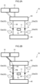
Fig. 1A is a schematic view illustrating an overview of an electrophoresis unit of a first embodiment; -
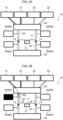
Fig. 1B is a schematic view illustrating a state in which a running solution is introduced into a second flow path in the electrophoresis unit ofFig. 1A ; -
Fig. 1C is a schematic view illustrating a state in which insulating fluid is introduced into the second flow path from the state ofFig. 1B ; -
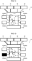
Fig. 1D is a schematic view illustrating a state in which the capillary flow path is filled with the running solution from the state ofFig. 1C ; -
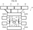
Fig. 1E is a schematic view illustrating a state in which a sample solution and insulating fluid are introduced into the first flow path and electrophoresis is performed from the state ofFig. 1D ; -
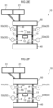
Fig. 2A is a schematic view illustrating an overview of an electrophoresis unit of a second embodiment; -
Fig. 2B is a schematic view illustrating a state in which a running solution is introduced into a second flow path in the electrophoresis unit ofFig. 2A ; -
Fig. 2C is a schematic view illustrating a state in which a capillary flow path is filled with the running solution from the state ofFig. 2B ; -
Fig. 2D is a schematic view illustrating a state in which a sample solution is introduced into a first flow path from the state ofFig. 2C ; -
Fig. 2E is a schematic view illustrating a state in which insulating fluid is introduced into the first flow path and the second flow path from the state ofFig. 2D ; -
Fig. 2F is a schematic view illustrating a state in which the first flow path and the second flow path are opened to outside air pressure and electrophoresis is performed from the state ofFig. 2E ; -
Fig. 3A is a schematic view illustrating an overview of an electrophoresis unit of a third embodiment; -
Fig. 3B is a schematic view illustrating a state in which a running solution is introduced into a second flow path in the electrophoresis unit ofFig. 3A ; -
Fig. 3C is a schematic view illustrating a state in which insulating fluid is introduced into the second flow path from the state ofFig. 3B ; -
Fig. 3D is a schematic view illustrating a state in which cleaning liquid is introduced into the second flow path from the state ofFig. 3C ; -
Fig. 3E is a schematic view illustrating a state in which a capillary flow path is filled with the running solution from the state ofFig. 3D ; -
Fig. 3F is a schematic view illustrating a state in which a sample solution, insulating fluid, and the cleaning liquid are introduced into the first flow path in this order from the state ofFig. 3E ; -
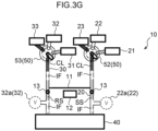
Fig. 3G is a schematic view illustrating a state in which, the first flow path and the second flow path are opened to outside air pressure while insulating fluid is introduced into the first flow path and the second flow path, and electrophoresis is performed from the state ofFig. 3F ; -
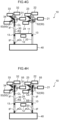
Fig. 4A is a schematic view illustrating an overview of an electrophoresis unit of a fourth embodiment; -
Fig. 4B is a schematic view illustrating a state in which pre-cleaning liquid is introduced into a second flow path in the electrophoresis unit ofFig. 4A ; -
Fig. 4C is a schematic view illustrating a state in which insulating fluid is introduced into the second flow path from the state ofFig. 4B ; -
Fig. 4D is a schematic view illustrating a state in which a running solution is introduced into the second flow path from the state ofFig. 4C ; -
Fig. 4E is a schematic view illustrating a state in which insulating fluid is introduced again into the second flow path from the state ofFig. 4D ; -
Fig. 4F is a schematic view illustrating a state in which cleaning liquid is introduced into the second flow path from the state ofFig. 4E ; -
Fig. 4G is a schematic view illustrating a state in which a capillary flow path is filled with the running solution from the state ofFig. 4F ; and -
Fig. 4H is a schematic view illustrating a state in which the pre-cleaning liquid, insulating fluid, the sample solution, insulating fluid, and the cleaning liquid are introduced into the first flow path in this order, subsequently the first flow path and the second flow path are opened to outside air pressure, and electrophoresis is performed from the state ofFig. 4G . - Hereinafter, embodiments in the invention will be described with reference to the drawings. The same reference numerals in the drawings indicate the same portions without any particular description. Moreover, the respective members and parts illustrated in each of the drawings are merely schematically illustrated, and the size and positional relationship of actual products are not necessarily accurately illustrated. In each of the drawings referred to below, the right side of a
capillary flow path 11 is defined as an upstream side, and the left side is defined as a downstream side, with respect to flow of a sample solution. - A first embodiment will be described with reference to
Fig. 1A to Fig. 1E .Fig. 1A is a schematic view illustrating an overview of anelectrophoresis unit 10 of the first embodiment. Moreover,Fig. 1B to Fig. 1E schematically illustrate a schematic procedure in which acapillary flow path 11 is filled with a running solution RS, and a sample solution SS is introduced into thecapillary flow path 11 at the start of electrophoresis in the present embodiment. - The electrophoresis unit 10 according to the present embodiment includes: the capillary flow path 11 through which a sample solution SS moves from an upstream side to downstream side in a state in which the capillary flow path 11 is filled with a running solution RS; a pair of electrodes 13 installed near (at) both ends of the capillary flow path 11; a detector 12 provided at an intermediate part of the capillary flow path 11; a first flow path 20, an intermediate part of which communicates with the upstream side of the capillary flow path 11, the first flow path 20 extending in a direction intersecting a longitudinal direction of the capillary flow path 11; a second flow path 30, an intermediate part of which communicates with the downstream side of the capillary flow path 11, the second flow path 30 extending in the direction intersecting the longitudinal direction of the capillary flow path 11; a first supply source 21 configured to supply the sample solution SS to the first flow path 20; a second supply source 31 configured to supply the running solution RS to the second flow path 30; a pump 40 configured to move the running solution RS from the second supply source 31 to the second flow path 30 and to move the sample solution SS from the first supply source 21 to the first flow path 20; a first auxiliary supply source 22 configured to supply, to the first flow path 20, insulating fluid IF that insulates the sample solution SS in contact with the electrode 13 in the first flow path 20; a second auxiliary supply source 32 configured to supply, to the second flow path 30, insulating fluid IF that insulates the running solution RS in contact with the electrode 13 in the second flow path 30; and a switch 50 configured to switch between supply and stop of fluid at least from the first supply source 21 and the second supply source 31 to the first flow path 20 and the second flow path 30.
- The
capillary flow path 11 is a capillary tube into which liquid is introduced by using a capillary phenomenon, or by pressurizing or aspirating, and is formed of a translucent material such as glass or transparent plastic. In theelectrophoresis unit 10, in a state in which thecapillary flow path 11 is filled with the running solution RS, a voltage is applied via the pair ofelectrodes 13 installed near (at) both ends of thecapillary flow path 11, so that the sample solution SS moves in the downstream direction to the opposite end in thecapillary flow path 11. Herein, a side at which the sample solution SS is supplied to thecapillary flow path 11 is referred to as an upstream side, and a side to which the sample solution SS moves is referred to as downstream side. - The running solution RS is, for example, a buffer solution or the like that is variously selected depending on the purpose of electrophoresis. The sample solution SS is, for example, a liquid sample collected from a living body, such as blood, plasma, saliva, or urine, and is preferably diluted to a suitable concentration with an appropriate buffer solution or the like according to the condition of electrophoresis.
- The
detector 12 is a device that optically detects a separated component of the sample solution SS having been moved, at the intermediate part of thecapillary flow path 11. - The
first flow path 20 is a flow path through which the sample solution SS is supplied from thefirst supply source 21 to an upstream end of thecapillary flow path 11 by thepump 40. Thefirst flow path 20 intersects with the longitudinal direction of thecapillary flow path 11, extends in any direction (preferably, a direction orthogonal to the longitudinal direction of the capillary flow path 11), and communicates with the upstream end of thecapillary flow path 11 at the intermediate part of thefirst flow path 20. Thefirst supply source 21 can be implemented with, for example, a reservoir or a syringe capable of temporarily storing the sample solution SS. Any excess sample solution SS is discharged from an end of the first flow path 20 (i.e., from a side opposite to the first supply source 21). Thepump 40 may be provided at either a supply side or a discharge side offirst flow path 20, or may be provided at both sides. In a case in which thepump 40 is provided at the supply side, thepump 40 moves (pushes) the sample solution SS to thefirst flow path 20. In a case in which thepump 40 is provided at the discharge side, thepump 40 aspirates the sample solution SS from thefirst flow path 20. In either case, the sample solution SS moves from thefirst supply source 21 to thefirst flow path 20. - The
second flow path 30 is a flow path through which the running solution RS is supplied from thesecond supply source 31 to a downstream end and the inside of thecapillary flow path 11 by thepump 40. Thesecond flow path 30 intersects with the longitudinal direction of thecapillary flow path 11, extends in any direction (preferably, a direction orthogonal to the longitudinal direction of the capillary flow path 11), and communicates with the downstream end of thecapillary flow path 11 at the intermediate part of thesecond flow path 30. Thesecond supply source 31 can be implemented with, for example, a reservoir or a syringe capable of temporarily storing the running solution RS. Any excess running solution RS is discharged from an end of the second flow path 30 (i.e., from a side opposite to the second supply source 31). Thepump 40 may be provided at either a supply side or a discharge side of thesecond flow path 30, or may be provided at both sides. In a case in which thepump 40 is provided at the supply side, thepump 40 moves (pushes) the running solution RS to thesecond flow path 30. In a case in which thepump 40 is provided at the discharge side, thepump 40 aspirates the running solution RS from thesecond flow path 30. In either case, the running solution RS moves from thesecond supply source 31 to thesecond flow path 30. In the present embodiment, thepump 40 is provided at the discharge side of thefirst flow path 20 and thesecond flow path 30. - The insulating fluid IF is fluid having insulating properties used for blocking, in the
first flow path 20 and thesecond flow path 30, electric conduction through the sample solution SS and the running solution RS in contact with theelectrodes 13 to the supply side or the discharge side. As the insulating fluid IF, air is most preferable, but other gas (e.g., nitrogen, carbon dioxide, and the like) or liquid (e.g., vegetable oil, mineral oil, and the like) having high insulating properties may be used. The insulating fluid IF is supplied from the firstauxiliary supply source 22 and the secondauxiliary supply source 32 to thefirst flow path 20 and thesecond flow path 30, respectively. The firstauxiliary supply source 22 and the secondauxiliary supply source 32 can be implemented with ventilation passages or valves opened to the outside from thefirst flow path 20 and thesecond flow path 30, respectively. - The
switch 50 switches between supply and stop of fluid at least from thefirst supply source 21 and thesecond supply source 31 to thefirst flow path 20 and thesecond flow path 30. In other words, theswitch 50 is a mechanism interposed between thefirst supply source 21 and thefirst flow path 20 and between thesecond supply source 31 and thesecond flow path 30, being capable of switching the flow path of the fluid. Theswitch 50 can be implemented with, for example, a rotary valve, a mechanism in which a plurality of valves are combined, or a mechanism moving a nozzle. As in the present embodiment, the firstauxiliary supply source 22 and the secondauxiliary supply source 32 may introduce the insulating fluid IF into thefirst flow path 20 and thesecond flow path 30 via theswitch 50, respectively. In the present embodiment, thefirst supply source 21 and thesecond supply source 31, as well as the firstauxiliary supply source 22 and the secondauxiliary supply source 32, are provided at the supply side of thefirst flow path 20 and thesecond flow path 30 via theswitch 50. - Moreover, as in the present embodiment,
fluid detection sensors 80 configured to detect arrival of fluid may be attached to thefirst flow path 20 and thesecond flow path 30. In the present embodiment, afirst sensor 82 is provided at each of the supply side and the discharge side with respect to theelectrode 13 in thefirst flow path 20. Moreover, asecond sensor 83 is provided at each of the supply side and the discharge side with respect to theelectrode 13 in thesecond flow path 30. - Hereinafter, procedures from supply of the running solution RS and the sample solution SS to execution of electrophoresis in the
electrophoresis unit 10 of the present embodiment will be described with reference toFig. 1B to Fig. 1E . - First, before the running solution RS and the sample solution SS are supplied, each of the
first flow path 20 and thesecond flow path 30 is filled with air serving as insulating fluid IF. From this state, as illustrated inFig. 1B , theswitch 50 connects thesecond supply source 31 to thesecond flow path 30, and the running solution RS is supplied to thesecond flow path 30 by aspiration by thepump 40. Then, when thesecond sensor 83 at the supply side detects a tip of the running solution RS, the supply of the running solution RS is stopped. - Next, as illustrated in
Fig. 1C , theswitch 50 switches the supply sources to connect the secondauxiliary supply source 32 to thesecond flow path 30, and insulating fluid IF is supplied to thesecond flow path 30 by aspiration by thepump 40. Then, as illustrated inFig. 1D , when the sensor at the discharge side detects the tip of the running solution RS, the supply of the insulating fluid IF is stopped. In this state, the running solution RS is retained in the downstream side of thecapillary flow path 11, and the running solution RS is interposed between the insulating fluid IF located at the supply side and the insulating fluid IF located at the discharge side with respect to the position of theelectrode 13. In this state, the running solution RS is introduced into thecapillary flow path 11 from the downstream side by a capillary phenomenon, pressurizing, aspirating, or the like. In a case in which the capillary phenomenon is used, it is necessary to open both ends of thecapillary flow path 11 to the atmospheric pressure. On the other hand, in a case in which the running solution RS is introduced into thecapillary flow path 11 by applying negative pressure or positive pressure, it is necessary to generate a pressure difference between the flow paths at both ends of the capillary. - Thereafter, the
switch 50 switches the supply sources to connect thefirst supply source 21 to thefirst flow path 20, and the sample solution SS is supplied to thefirst flow path 20 by aspiration by thepump 40. Then, when thefirst sensor 82 at the supply side detects a tip of the sample solution SS, the supply of the sample solution SS is stopped. Next, theswitch 50 switches the supply sources to connect the firstauxiliary supply source 22 to thefirst flow path 20, and insulating fluid IF is supplied to thefirst flow path 20 by aspiration by thepump 40. Then, as illustrated inFig. 1E , when the sensor at the discharge side detects the tip of the sample solution SS, the supply of the insulating fluid IF is stopped. In this state, the sample solution SS is retained in the upstream side of thecapillary flow path 11, and the sample solution SS is interposed between the insulating fluid IF located at the supply side and the insulating fluid IF located at the discharge side with respect to the position of theelectrode 13. In this state, a voltage is applied between theelectrodes 13 at both ends of thecapillary flow path 11, whereby an electroosmotic flow is generated, so that the sample solution SS moves toward the downstream side in thecapillary flow path 11. The components separated by electrophoresis are optically detected by thedetector 12. At this time, since theelectrodes 13 provided in thefirst flow path 20 and thesecond flow path 30 are interposed between the insulating fluid IF on both the supply side and the discharge side, electric leakage from theelectrodes 13 to the supply side and the discharge side of theelectrophoresis unit 10 can be prevented. - The present embodiment described above implements an electrophoresis method that uses the capillary flow path 11 through which the sample solution SS moves from the upstream side to the downstream side in a state in which the capillary flow path 11 is filled with the running solution, the detector 12 provided at the intermediate part of the capillary flow path 11, the first flow path 20 the intermediate part of which communicates with the upstream side of the capillary flow path 11, the first flow path 20 extending in the direction intersecting the longitudinal direction of the capillary flow path 11, and the second flow path 30 the intermediate part of which communicates with the downstream side of the capillary flow path 11, the second flow path 30 extending in the direction intersecting the longitudinal direction of the capillary flow path 11, the electrophoresis method including: introducing the running solution RS into the second flow path 30; introducing the running solution RS from the second flow path 30 into the capillary flow path 11; introducing the sample solution SS into the first flow path 20; introducing insulating fluid IF into the second flow path 30 so as to interpose the running solution RS at the position in communication with the capillary flow path 11 in the insulating fluid IF; introducing insulating fluid IF into the first flow path 20 so as to interpose the sample solution SS at the position in communication with the capillary flow path 11 in the insulating fluid IF; and applying the voltage between the upstream side and the downstream side of the capillary flow path 11.
- In the electrophoresis method described above, it is preferable to further include: introducing insulating fluid IF into the
second flow path 30 before and after introducing the running solution RS into thesecond flow path 30; and introducing insulating fluid IF into thefirst flow path 20 before and after introducing the sample solution SS into thefirst flow path 20. - In the present embodiment, since it is not necessary to fill the entire flow path with liquid, the amount of liquid for measurement of the sample by electrophoresis can be minimized. Herein, the volume of the flow path can be appropriately designed. In this case, the
electrophoresis unit 10 can also be designed to, after introducing a known amount of fluid into the flow path, introduce another fluid. Thefluid detection sensor 80 described above is unnecessary in this case. - Note that, although, in the present embodiment, the
pump 40 is provided as a liquid discharge unit at the discharge side of thefirst flow path 20 and thesecond flow path 30, thepump 40 may be provided as part of the composition of theswitch 50 at the supply side. Moreover, the firstauxiliary supply source 22 and the secondauxiliary supply source 32 may be integrated into a single structure to be shared by thefirst flow path 20 and thesecond flow path 30. - A second embodiment will be described with reference to
Fig. 2A to Fig. 2F .Fig. 2A is a schematic view illustrating an overview of theelectrophoresis unit 10 of the second embodiment. Moreover,Fig. 2B to Fig. 2F schematically illustrate a schematic procedure in which the running solution RS and the sample solution SS are introduced into thecapillary flow path 11 and electrophoresis is performed in the present embodiment. - The configurations of the
capillary flow path 11, thedetector 12, thefirst flow path 20, and thesecond flow path 30, and the meanings of the sample solution SS, the running solution RS, and the insulating fluid IF are the same as those of the first embodiment. - In the present embodiment, the
first supply source 21 and thesecond supply source 31 are provided at the supply side of thefirst flow path 20 and thesecond flow path 30 via theswitch 50. Similarly to the first embodiment, thepump 40 is provided at the discharge side of thefirst flow path 20 and thesecond flow path 30. - In the
electrophoresis unit 10 in the present embodiment, afirst valve 22a configured to open thefirst flow path 20 to the atmospheric pressure is provided as the firstauxiliary supply source 22, and asecond valve 32a configured to open thesecond flow path 30 to atmospheric pressure is provided as the secondauxiliary supply source 32. In the present embodiment, thefirst valve 22a is provided at each of the supply side and the discharge side with respect to theelectrode 13 in thefirst flow path 20. Moreover, thesecond valve 32a is provided at each of the supply side and the discharge side with respect to theelectrode 13 in thesecond flow path 30. - Hereinafter, procedures from supply of the running solution RS and the sample solution SS to execution of electrophoresis in the
electrophoresis unit 10 of the present embodiment will be described with reference toFig. 2B to Fig. 2F . - First, as illustrated in
Fig. 2B , theswitch 50 connects thesecond supply source 31 to thesecond flow path 30 to open the flow path, and the running solution RS is supplied to thesecond flow path 30 by aspiration by thepump 40. When thesecond flow path 30 is filled with the running solution RS, theswitch 50 closes the flow path to stop the supply of the running solution RS. - Next, as illustrated in
Fig. 2C , the running solution RS is introduced into thecapillary flow path 11 from the downstream side by a capillary phenomenon, pressurizing, aspirating, or the like. In a case in which the capillary phenomenon is used, it is necessary to open both ends of thecapillary flow path 11 to the atmospheric pressure. On the other hand, in a case in which the running solution RS is introduced into thecapillary flow path 11 by applying negative pressure or positive pressure, it is necessary to generate a pressure difference between the flow paths at both ends of the capillary. - Next, as illustrated in
Fig. 2D , theswitch 50 connects thefirst supply source 21 to thefirst flow path 20 to open the flow path, and the sample solution SS is supplied to thefirst flow path 20 by aspiration by thepump 40. When thefirst flow path 20 is filled with the sample solution SS, theswitch 50 closes the flow path to stop the supply of the sample solution SS. - Subsequently, as illustrated in
Fig. 2E , in thefirst flow path 20 and thesecond flow path 30, thefirst valve 22a and thesecond valve 32a at the discharge side are opened, and insulating fluid IF (e.g., air) is introduced from the outside at the discharge side with respect to each of theelectrodes 13 of thefirst flow path 20 and thesecond flow path 30. Herein, since the supply side of thefirst flow path 20 and the supply side of thesecond flow path 30 are closed spaces, the fluid in thecapillary flow path 11 does not move. Then, thefirst valve 22a and thesecond valve 32a at the discharge side are closed. - Then, as illustrated in
Fig. 2F , in thefirst flow path 20 and thesecond flow path 30, thefirst supply source 21 and thesecond supply source 31 are communicated with each other by opening of theswitch 50, and at the same time, thefirst valve 22a and thesecond valve 32a at the supply side are opened, and insulating fluid IF (e.g., air) is introduced from the outside at the supply side with respect to each of theelectrodes 13 of thefirst flow path 20 and thesecond flow path 30. After the insulating fluid IF is introduced, in thefirst flow path 20 and thesecond flow path 30, the communication with thefirst supply source 21 and the communication with thesecond supply source 31 are blocked by closing of theswitch 50. In this way, by opening thefirst valve 22a and thesecond valve 32a at the supply side of thefirst flow path 20 and thesecond flow path 30, both ends of thecapillary flow path 11 are opened to the atmospheric pressure, and the external force due to the differential pressure with the outside air pressure does not act on the fluid in thecapillary flow path 11. - In this stage, the running solution RS is retained in the downstream side of the
capillary flow path 11, and the running solution RS is interposed between the insulating fluid IF located at the supply side and the insulating fluid IF located at the discharge side with respect to the position of theelectrode 13. At the same time, the sample solution SS is retained in the upstream side of thecapillary flow path 11, and the sample solution SS is interposed between the insulating fluid IF located at the supply side and the insulating fluid IF located at the discharge side with respect to the position of theelectrode 13. In this state, a voltage is applied between theelectrodes 13 at both ends of thecapillary flow path 11, whereby an electroosmotic flow is generated, so that the sample solution SS moves toward the downstream side in thecapillary flow path 11. The components separated by electrophoresis are optically detected by thedetector 12. At this time, since theelectrodes 13 provided in thefirst flow path 20 and thesecond flow path 30 are interposed between the insulating fluid IF on both the supply side and the discharge side, electric leakage from theelectrodes 13 to the supply side and the discharge side of theelectrophoresis unit 10 can be prevented. - The present embodiment described above implements an electrophoresis method that uses the capillary flow path 11 through which the sample solution SS moves from the upstream side to the downstream side, the detector 12 provided at the intermediate part of the capillary flow path 11, the first flow path 20, the intermediate part of which communicates with the upstream side of the capillary flow path 11, the first flow path 20 extending in the direction intersecting the longitudinal direction of the capillary flow path 11, and the second flow path 30 the intermediate part of which communicates with the downstream side of the capillary flow path 11, the second flow path 30 extending in the direction intersecting the longitudinal direction of the capillary flow path 11, the electrophoresis method including: introducing the running solution RS into the second flow path 30; introducing the running solution RS from the second flow path 30 into the capillary flow path 11; introducing the sample solution SS into the first flow path 20; introducing insulating fluid IF into the second flow path 30 so as to interpose the running solution RS at the position in communication with the capillary flow path 11 in the insulating fluid IF; introducing insulating fluid IF into the first flow path 20 so as to interpose the sample solution SS at the position in communication with the capillary flow path 11 in the insulating fluid IF; and applying the voltage between the upstream side and the downstream side of the capillary flow path 11.
- In the electrophoresis method described above, it is preferable to include: introducing the running solution RS into the
second flow path 30 and then introducing the insulating fluid IF so as to interpose the position in communication with thecapillary flow path 11 in the insulating fluid IF; and introducing the sample solution SS into thefirst flow path 20 and then introducing insulating fluid IF so as to interpose the position in communication with thecapillary flow path 11 in the insulating fluid IF. - Note that, although, in the present embodiment, the
pump 40 is provided as a liquid discharge unit at the discharge side of thefirst flow path 20 and thesecond flow path 30, thepump 40 may be provided as part of the composition of theswitch 50 at the supply side. - A third embodiment will be described with reference to
Fig. 3Ato Fig. 3G .Fig. 3A is a schematic view illustrating an overview of theelectrophoresis unit 10 of the third embodiment. Moreover,Fig. 3B to Fig. 3G schematically illustrate a schematic procedure in which the running solution RS and the sample solution SS are introduced into thecapillary flow path 11 and electrophoresis is performed in the present embodiment. - The configurations of the
capillary flow path 11, thedetector 12, thefirst flow path 20, and thesecond flow path 30, and the meanings of the sample solution SS, the running solution RS, and the insulating fluid IF are the same as those of the first embodiment. - In the present embodiment, the
first supply source 21, the firstauxiliary supply source 22, and a cleaningliquid supply source 23 are provided at the supply side of thefirst flow path 20 via afirst switch 52 serving as theswitch 50. Moreover, thesecond supply source 31, the secondauxiliary supply source 32, and a cleaningliquid supply source 33 are provided at the supply side of thesecond flow path 30 via asecond switch 53 serving as theswitch 50. The firstauxiliary supply source 22 and the secondauxiliary supply source 32 have the same meaning as in the first embodiment. Both thefirst switch 52 and thesecond switch 53 include a rotary valve, a mechanism in which a plurality of valves are combined, or a mechanism moving a nozzle. - The cleaning
liquid supply sources first flow path 20, thesecond flow path 30, and thecapillary flow path 11 after the end of electrophoresis, to thefirst flow path 20 and thesecond flow path 30, respectively. As the cleaning liquid CL, for example, liquid in which a surfactant is added to appropriate buffer solution or the like can be used. That is, in the present embodiment, the cleaning liquid CL is introduced into thefirst flow path 20 via theswitch 50 after the sample solution SS is introduced into thefirst flow path 20, and the cleaning liquid CL is introduced into thesecond flow path 30 via theswitch 50 after the running solution RS is introduced into thesecond flow path 30. - Moreover, in the present embodiment, the
first valve 22a configured to open thefirst flow path 20 to atmospheric pressure is further provided as the firstauxiliary supply source 22 at the discharge side with respect to the position of theelectrode 13, and thesecond valve 32a configured to open thesecond flow path 30 to the atmospheric pressure is further provided as the secondauxiliary supply source 32 at the discharge side with respect to the position of theelectrode 13. Similarly to the first embodiment, thepump 40 is provided at the discharge side of thefirst flow path 20 and thesecond flow path 30. - Hereinafter, from supply of the running solution RS and the sample solution SS to execution of electrophoresis in the
electrophoresis unit 10 of the present embodiment will be described with reference toFig. 3B to Fig. 3G . - First, as illustrated in
Fig. 3B , thesecond switch 53 connects thesecond supply source 31 to thesecond flow path 30, and the running solution RS is supplied to thesecond flow path 30 by aspiration by thepump 40. Subsequently, as illustrated inFig. 3C , thesecond switch 53 switches the supply sources to connect the secondauxiliary supply source 32 to thesecond flow path 30, and aspiration by thepump 40 supplies insulating fluid IF to thesecond flow path 30. - Next, as illustrated in
Fig. 3D , thesecond switch 53 switches the supply sources to connect the cleaningliquid supply source 33 to thesecond flow path 30, and the cleaning liquid CL is supplied to thesecond flow path 30 by aspiration by thepump 40. Then, as illustrated inFig. 3E , the running solution RS is introduced into thecapillary flow path 11 from the downstream side by a capillary phenomenon, pressurizing, aspirating, or the like. In a case in which the capillary phenomenon is used, it is necessary to open both ends of thecapillary flow path 11 to the atmospheric pressure. On the other hand, in a case in which the running solution RS is introduced into thecapillary flow path 11 by applying negative pressure or positive pressure, it is necessary to generate a pressure difference between the flow paths at both ends of the capillary. - From this state, the
first switch 52 connects thefirst supply source 21 to thefirst flow path 20, and the sample solution SS is supplied to thefirst flow path 20 by aspiration by thepump 40. Subsequently, thefirst switch 52 switches the supply sources to connect the firstauxiliary supply source 22 to thefirst flow path 20, and insulating fluid IF is supplied to thefirst flow path 20 by aspiration by thepump 40. Next, thefirst switch 52 switches the supply sources to connect the cleaningliquid supply source 23 to thefirst flow path 20, and the cleaning liquid CL is supplied to thefirst flow path 20 by aspiration by thepump 40. Then, as illustrated inFig. 3F , both thefirst switch 52 and thesecond switch 53 transition to a closed state, and the supply side of thefirst flow path 20 and the supply side of thesecond flow path 30 become closed spaces. - Subsequently, as illustrated in
Fig. 3G , in thefirst flow path 20 and thesecond flow path 30, thefirst valve 22a and thesecond valve 32a at the discharge side are opened, and insulating fluid IF is introduced from the outside at the discharge side with respect to each of theelectrodes 13 of thefirst flow path 20 and thesecond flow path 30. In this way, by opening thefirst valve 22a and thesecond valve 32a at the discharge side in thefirst flow path 20 and thesecond flow path 30, both ends of thecapillary flow path 11 are opened to the atmospheric pressure, and the external force due to the differential pressure with the outside air pressure does not act on the fluid in thecapillary flow path 11. - In this state, a voltage is applied between the
electrodes 13 at both ends of thecapillary flow path 11, whereby an electroosmotic flow is generated, so that the sample solution SS moves toward the downstream side in thecapillary flow path 11. The components separated by electrophoresis are optically detected by thedetector 12. At this time, since theelectrodes 13 provided in thefirst flow path 20 and thesecond flow path 30 are interposed between the insulating fluid IF on both the supply side and the discharge side, electric leakage from theelectrodes 13 to the supply side and the discharge side of theelectrophoresis unit 10 can be prevented. - After the electrophoresis is completed, aspiration in the
first flow path 20 and thesecond flow path 30 by thepump 40 can cause thefirst flow path 20, thesecond flow path 30, and thecapillary flow path 11 to be cleaned with the cleaning liquid CL. - The present embodiment described above implements an electrophoresis method that uses the capillary flow path 11 through which the sample solution SS moves from the upstream side to the downstream side, the detector 12 provided at the intermediate part of the capillary flow path 11, the first flow path 20, the intermediate part of which communicates with the upstream side of the capillary flow path 11, the first flow path 20 extending in the direction intersecting the longitudinal direction of the capillary flow path 11, and the second flow path 30, the intermediate part of which communicates with the downstream side of the capillary flow path 11, the second flow path 30 extending in the direction intersecting the longitudinal direction of the capillary flow path 11, the electrophoresis method including: introducing the running solution RS into the second flow path 30; introducing the running solution RS from the second flow path 30 into the capillary flow path 11; introducing the sample solution SS into the first flow path 20; introducing insulating fluid IF into the second flow path 30 so as to interpose the running solution RS at the position in communication with the capillary flow path 11 in the insulating fluid IF; introducing insulating fluid IF into the first flow path 20 so as to interpose the sample solution SS at the position in communication with the capillary flow path 11 in the insulating fluid IF; and applying the voltage between the upstream side and the downstream side of the capillary flow path 11.
- In the electrophoresis method described above, it is preferable to further include: introducing insulating fluid IF into the
second flow path 30 after introducing the running solution RS into thesecond flow path 30, and with respect to the insulating fluid IF, further introducing insulating fluid IF into thesecond flow path 30 so as to interpose the position in communication with thecapillary flow path 11 in the insulating fluid IF; and introducing insulating fluid IF into thefirst flow path 20 after introducing the sample solution SS into thefirst flow path 20, and with respect to the insulating fluid IF, further introducing insulating fluid IF into thefirst flow path 20 so as to interpose the position in communication with thecapillary flow path 11 in the insulating fluid IF. - In the electrophoresis method described above, it is preferable to further include: introducing the cleaning liquid CL into the
second flow path 30 after introducing the running solution RS into thesecond flow path 30; and introducing the cleaning liquid CL into thefirst flow path 20 after introducing the sample solution SS into thefirst flow path 20. - Note that, although, in the present embodiment, the
pump 40 is provided as a liquid discharge unit at the discharge side of thefirst flow path 20 and thesecond flow path 30, thepump 40 may be provided as part of the composition of theswitch 50 at the supply side. The firstauxiliary supply source 22 and the secondauxiliary supply source 32 may be integrated into a single structure to be shared by thefirst flow path 20 and thesecond flow path 30. The two cleaningliquid supply sources first flow path 20 and thesecond flow path 30. - A fourth embodiment will be described with reference to
Fig. 4A to Fig. 4H .Fig. 4A is a schematic view illustrating an overview of theelectrophoresis unit 10 of the fourth embodiment. Moreover,Fig. 4B to Fig. 4H schematically illustrate a schematic procedure in which the running solution RS and the sample solution SS are introduced into thecapillary flow path 11 and electrophoresis is performed in the present embodiment. - The configurations of the
capillary flow path 11, thedetector 12, thefirst flow path 20, and thesecond flow path 30, and the meanings of the sample solution SS, the running solution RS, and the insulating fluid IF are the same as those of the first embodiment. - In the present embodiment, the
first supply source 21, the firstauxiliary supply source 22, the cleaningliquid supply source 23, and a pre-cleaningliquid supply source 24 are provided at the supply side of thefirst flow path 20 via thefirst switch 52 serving as theswitch 50. Moreover, thesecond supply source 31, the secondauxiliary supply source 32, the cleaningliquid supply source 33, and a pre-cleaningliquid supply source 34 are provided at the supply side of thesecond flow path 30 via thesecond switch 53 serving as theswitch 50. The firstauxiliary supply source 22 and the secondauxiliary supply source 32 have the same meaning as in the first embodiment. Both thefirst switch 52 and thesecond switch 53 include a rotary valve, a mechanism in which a plurality of valves are combined, or a mechanism moving a nozzle. - The pre-cleaning
liquid supply sources first flow path 20 and thesecond flow path 30 before the start of electrophoresis to thefirst flow path 20 and thesecond flow path 30, respectively. The cleaningliquid supply sources first flow path 20, thesecond flow path 30, and thecapillary flow path 11 after the end of electrophoresis, to thefirst flow path 20 and thesecond flow path 30, respectively. As the cleaning liquid CL and the pre-cleaning liquid pCL, for example, liquid in which a surfactant is added to appropriate buffer solution or the like can be used. That is, in the present embodiment, the pre-cleaning liquid pCL is introduced into thefirst flow path 20 via theswitch 50 before the sample solution SS is introduced into thefirst flow path 20, and the pre-cleaning liquid pCL is introduced into thesecond flow path 30 via theswitch 50 before the running solution RS is introduced into thesecond flow path 30. Furthermore, in the present embodiment, the cleaning liquid CL is introduced into thefirst flow path 20 via theswitch 50 after the sample solution SS is introduced into thefirst flow path 20, and the cleaning liquid CL is introduced into thesecond flow path 30 via theswitch 50 after the running solution RS is introduced into thesecond flow path 30. - Hereinafter, procedures from supply of the running solution RS and the sample solution SS to execution of electrophoresis in the
electrophoresis unit 10 of the present embodiment will be described with reference toFig. 4B to Fig 4H . - First, as illustrated in
Fig. 4B , thesecond switch 53 connects the pre-cleaningliquid supply source 34 to thesecond flow path 30, and the pre-cleaning liquid pCL is supplied to thesecond flow path 30 by aspiration by thepump 40. Subsequently, as illustrated inFig. 4C , thesecond switch 53 switches the supply sources to connect the secondauxiliary supply source 32 to thesecond flow path 30, and insulating fluid IF is supplied to thesecond flow path 30 by aspiration by thepump 40. - Next, as illustrated in
Fig. 4D , switching the supply sources, thesecond switch 53 connects thesecond supply source 31 to thesecond flow path 30, and the running solution RS is supplied to thesecond flow path 30 by aspiration by thepump 40. Subsequently, as illustrated inFig. 4E , thesecond switch 53 switches the supply sources to connect the secondauxiliary supply source 32 to thesecond flow path 30, and insulating fluid IF is supplied to thesecond flow path 30 by aspiration by thepump 40. - Next, as illustrated in
Fig. 4F , thesecond switch 53 switches the supply sources to connect the cleaningliquid supply source 33 to thesecond flow path 30, and the cleaning liquid CL is supplied to thesecond flow path 30 by aspiration by thepump 40. As illustrated inFig. 4G , the running solution RS is introduced into thecapillary flow path 11 from the downstream side by a capillary phenomenon, pressurizing, aspirating, or the like. In a case in which the capillary phenomenon is used, it is necessary to open both ends of thecapillary flow path 11 to the atmospheric pressure. On the other hand, in a case in which the running solution RS is introduced into thecapillary flow path 11 by applying negative pressure or positive pressure, it is necessary to generate a pressure difference between the flow paths at both ends of the capillary. - From this state, the
first switch 52 connects the pre-cleaningliquid supply source 24 to thefirst flow path 20, and the pre-cleaning liquid pCL is supplied to thefirst flow path 20 by aspiration by thepump 40. Subsequently, thefirst switch 52 switches the supply sources to connect the firstauxiliary supply source 22 to thefirst flow path 20, and insulating fluid IF is supplied to thefirst flow path 20 by aspiration by thepump 40. Next, switching the supply sources, thefirst switch 52 connects thefirst supply source 21 to thefirst flow path 20, and the sample solution SS is supplied to thefirst flow path 20 by aspiration by thepump 40. Subsequently, thefirst switch 52 switches the supply sources to connect the firstauxiliary supply source 22 to thefirst flow path 20, and insulating fluid IF is supplied to thefirst flow path 20 by aspiration by thepump 40. Then, thefirst switch 52 switches the supply sources to connect the cleaningliquid supply source 23 to thefirst flow path 20, and the cleaning liquid CL is supplied to thefirst flow path 20 by aspiration by thepump 40. - In this state, as illustrated in
Fig. 4H , thefirst switch 52 connects thefirst flow path 20 to the firstauxiliary supply source 22, so that the supply side of thefirst flow path 20 becomes anopen path 55 opened to the atmospheric pressure. Similarly, as illustrated inFig. 4H , thesecond switch 53 connects thesecond flow path 30 to the secondauxiliary supply source 32, so that the supply side of thesecond flow path 30 also becomes anopen path 55 opened to the atmospheric pressure. In this way, the supply side of thefirst flow path 20 and the supply side of thesecond flow path 30 become theopen paths 55 and are opened to the atmospheric pressure, so that the external force due to the differential pressure with the outside air pressure does not act on the fluid in thecapillary flow path 11. That is, in theelectrophoresis unit 10 of the present embodiment, theswitch 50 is capable of switching each of thefirst flow path 20 and thesecond flow path 30 to theopen path 55 to be opened to the atmospheric pressure. - In the state illustrated in
Fig. 4H , a voltage is applied between theelectrodes 13 at both ends of thecapillary flow path 11, whereby an electroosmotic flow is generated, so that the sample solution SS moves toward the downstream side in thecapillary flow path 11. The components separated by electrophoresis are optically detected by thedetector 12. At this time, since theelectrodes 13 provided in thefirst flow path 20 and thesecond flow path 30 are interposed between the insulating fluid IF on both the supply side and the discharge side, electric leakage from theelectrodes 13 to the supply side and the discharge side of theelectrophoresis unit 10 can be prevented. - Then, after the electrophoresis is completed, aspiration in the
first flow path 20 and thesecond flow path 30 by thepump 40 can cause thefirst flow path 20, thesecond flow path 30, and thecapillary flow path 11 to be cleaned with the cleaning liquid CL. - The present embodiment described above implements an electrophoresis method that uses the capillary flow path 11 through which the sample solution SS moves from the upstream side to the downstream side, the detector 12 provided at the intermediate part of the capillary flow path 11, the first flow path 20, the intermediate part of which communicates with the upstream side of the capillary flow path 11, the first flow path 20 extending in the direction intersecting the longitudinal direction of the capillary flow path 11, and the second flow path 30, the intermediate part of which communicates with the downstream side of the capillary flow path 11, the second flow path 30 extending in the direction intersecting the longitudinal direction of the capillary flow path 11, the electrophoresis method including: introducing the running solution RS into the second flow path 30; introducing the running solution RS from the second flow path 30 into the capillary flow path 11; introducing the sample solution SS into the first flow path 20; introducing insulating fluid IF into the second flow path 30 so as to interpose the running solution RS at the position in communication with the capillary flow path 11 in the insulating fluid IF; introducing insulating fluid IF into the first flow path 20 so as to interpose the sample solution SS at the position in communication with the capillary flow path 11 in the insulating fluid IF; and applying the voltage between the upstream side and the downstream side of the capillary flow path 11.
- In the electrophoresis method described above, it is preferable to further include: introducing insulating fluid IF into the
second flow path 30 after introducing the running solution RS into thesecond flow path 30, and with respect to the insulating fluid IF, further introducing insulating fluid IF into thesecond flow path 30 so as to interpose the position in communication with thecapillary flow path 11 in the insulating fluid IF; and introducing insulating fluid IF into thefirst flow path 20 after introducing the sample solution SS into thefirst flow path 20, and with respect to the insulating fluid IF, further introducing insulating fluid IF into thefirst flow path 20 so as to interpose the position in communication with thecapillary flow path 11 in the insulating fluid IF. - In the electrophoresis method described above, it is preferable to further include: introducing the cleaning liquid CL into the
second flow path 30 after introducing the running solution RS into thesecond flow path 30; and introducing the cleaning liquid CL into thefirst flow path 20 after introducing the sample solution SS into thefirst flow path 20. - In the electrophoresis method described above, it is preferable to further include: introducing the pre-cleaning liquid pCL into the
second flow path 30 before introducing the running solution RS into thesecond flow path 30; and introducing the pre-cleaning liquid pCL into thefirst flow path 20 before introducing the sample solution SS into thefirst flow path 20. - Note that, although, in the present embodiment, the
pump 40 is provided as a liquid discharge unit at the discharge side of thefirst flow path 20 and thesecond flow path 30, thepump 40 may be provided as part of the composition of theswitch 50 at the supply side. The firstauxiliary supply source 22 and the secondauxiliary supply source 32 may be integrated into a single structure to be shared by thefirst flow path 20 and thesecond flow path 30. The two cleaningliquid supply sources first flow path 20 and thesecond flow path 30. The two pre-cleaningliquid supply sources first flow path 20 and thesecond flow path 30. - The technique of the present invention can be utilized for an electrophoresis unit and an electrophoresis method that perform capillary electrophoresis.
Claims (13)
- An electrophoresis unit (10), comprising:a capillary flow path (11) through which a sample solution (SS) moves from an upstream side to a downstream side in a state in which the capillary flow path (11) is filled with a running solution (RS);a pair of electrodes (13) installed near both ends of the capillary flow path (11);a detector (12) provided at an intermediate part of the capillary flow path (11);a first flow path (20), an intermediate part of which communicates with the upstream side of the capillary flow path (11), the first flow path (20) extending in a direction intersecting a longitudinal direction of the capillary flow path (11);a second flow path (30), an intermediate part of which communicates with the downstream side of the capillary flow path (11), the second flow path (30) extending in the direction intersecting the longitudinal direction;a first supply source (21) configured to supply the sample solution (SS) to the first flow path (20);a second supply source (31) configured to supply the running solution (RS) to the second flow path (30);a pump (40) configured to move the running solution (RS) from the second supply source (31) to the second flow path (30) and to move the sample solution (SS) from the first supply source (21) to the first flow path (20);a first auxiliary supply source (22) configured to supply, to the first flow path (20), insulating fluid (IF) that insulates the sample solution (SS) in contact with the electrode (13) in the first flow path (20);a second auxiliary supply source (32) configured to supply, to the second flow path (30), insulating fluid (IF) that insulates the running solution (RS) in contact with the electrode (13) in the second flow path (30); anda switch (50; 52, 53) configured to switch between supply and stop of fluid at least from the first supply source (21) and the second supply source (31) to the first flow path (20) and the second flow path (30).
- The electrophoresis unit (10) according to claim 1, wherein the first auxiliary supply source (22) and the second auxiliary supply source (32) introduce the insulating fluid (IF) into the first flow path (20) and the second flow path (30), via the switch (50; 52, 53), respectively.
- The electrophoresis unit (10) according to claim 1 or 2, wherein a fluid detection sensor (80) configured to detect arrival of fluid is attached to each of the first flow path (20) and the second flow path (30).
- The electrophoresis unit (10) according to claim 1 or claim 2, wherein:a first valve (22a) configured to open the first flow path (20) to atmospheric pressure is provided as the first auxiliary supply source (22), anda second valve (32a) configured to open the second flow path (30) to atmospheric pressure is provided as the second auxiliary supply source (32).
- The electrophoresis unit (10) according to claim 1 or 2, wherein the switch (52, 53) is capable of switching each of the first flow path (20) and the second flow path (30) to an open path to be opened to atmospheric pressure.
- The electrophoresis unit (10) according to any one of claims 1 to 5, wherein:a cleaning liquid (CL) is introduced into the first flow path (20), via the switch (52), after the sample solution (SS) is introduced into the first flow path (20), andthe cleaning liquid (CL) is introduced into the second flow path (30), via the switch (53), after the running solution (RS) is introduced into the second flow path (30).
- The electrophoresis unit (10) according to claim 6, wherein:a pre-cleaning liquid (pCL) is introduced into the first flow path (20), via the switch (52), before the sample solution (SS) is introduced into the first flow path (20), andthe pre-cleaning liquid (pCL) is introduced into the second flow path (30), via the switch (53), before the running solution (RS) is introduced into the second flow path (30).
- An electrophoresis method that uses:a capillary flow path (11) through which a sample solution (SS) moves from an upstream side to a downstream side in a state in which the capillary flow path (11) is filled with a running solution (RS),a detector (12) provided at an intermediate part of the capillary flow path (11),a first flow path (20), an intermediate part of which communicates with the upstream side of the capillary flow path (11), the first flow path (20) extending in a direction intersecting a longitudinal direction of the capillary flow path (11), anda second flow path (30), an intermediate part of which communicates with the downstream side of the capillary flow path (11), the second flow path (30) extending in the direction intersecting the longitudinal direction,the electrophoresis method comprising:introducing the running solution (RS) into the second flow path (30);introducing the running solution (RS) from the second flow path (30) into the capillary flow path (11);introducing the sample solution (SS) into the first flow path (20);introducing insulating fluid (IF) into the second flow path (30) so as to interpose the running solution (RS), at a position in communication with the capillary flow path (11), in the insulating fluid (IF);introducing insulating fluid (IF) into the first flow path (20) so as to interpose the sample solution (SS), at a position in communication with the capillary flow path (11), in the insulating fluid (IF); andapplying a voltage between the upstream side and the downstream side of the capillary flow path (11).
- The electrophoresis method according to claim 8, further comprising:introducing the insulating fluid (IF) into the second flow path (30) before and after introducing the running solution (RS) into the second flow path (30); andintroducing the insulating fluid (IF) into the first flow path (20) before and after introducing the sample solution (SS) into the first flow path (20).
- The electrophoresis method according to claim 8, further comprising:introducing the running solution (RS) into the second flow path (30) and then introducing the insulating fluid (IF) so as to interpose the position in communication with the capillary flow path (11) in the insulating fluid (IF); andintroducing the sample solution (SS) into the first flow path (20) and then introducing the insulating fluid (IF) so as to interpose the position in communication with the capillary flow path (11) in the insulating fluid (IF).
- The electrophoresis method according to claim 8, further comprising:introducing the insulating fluid (IF) into the second flow path (30) after introducing the running solution (RS) into the second flow path (30), and with respect to the insulating fluid (IF), further introducing the insulating fluid (IF) into the second flow path (30) so as to interpose the position in communication with the capillary flow path (11) in the insulating fluid (IF); andintroducing the insulating fluid (IF) into the first flow path (20) after introducing the sample solution (SS) into the first flow path (20), and with respect to the insulating fluid (IF), further introducing the insulating fluid (IF) into the first flow path (20) so as to interpose the position in communication with the capillary flow path (11) in the insulating fluid (IF).
- The electrophoresis method according to any one of claims 8 to 11, further comprising:introducing a cleaning liquid (CL) into the second flow path (30) after introducing the running solution (RS) into the second flow path (30); andintroducing the cleaning liquid (CL) into the first flow path (20) after introducing the sample solution (SS) into the first flow path (20).
- The electrophoresis method according to claim 12, further comprising:introducing a pre-cleaning liquid (pCL) into the second flow path (30) before introducing the running solution (RS) into the second flow path (30); andintroducing the pre-cleaning liquid (pCL) into the first flow path (20) before introducing the sample solution (SS) into the first flow path (20).
Applications Claiming Priority (1)
| Application Number | Priority Date | Filing Date | Title |
|---|---|---|---|
| JP2023185912 | 2023-10-30 |
Publications (2)
| Publication Number | Publication Date |
|---|---|
| EP4549924A1 true EP4549924A1 (en) | 2025-05-07 |
| EP4549924B1 EP4549924B1 (en) | 2026-04-15 |
Family
ID=93289056
Family Applications (1)
| Application Number | Title | Priority Date | Filing Date |
|---|---|---|---|
| EP24208915.9A Active EP4549924B1 (en) | 2023-10-30 | 2024-10-25 | Electrophoresis unit and electrophoresis method with insulating fluid |
Country Status (4)
| Country | Link |
|---|---|
| US (1) | US20250137966A1 (en) |
| EP (1) | EP4549924B1 (en) |
| JP (1) | JP2025075024A (en) |
| CN (1) | CN119915886A (en) |
Citations (3)
| Publication number | Priority date | Publication date | Assignee | Title |
|---|---|---|---|---|
| JP2005214710A (en) | 2004-01-28 | 2005-08-11 | Shimadzu Corp | Microchip processing method and apparatus |
| US20160320286A1 (en) * | 2014-02-26 | 2016-11-03 | Kabushiki Kaisha Toshiba | Particle inspection unit and particle inspection system |
| JP2017161233A (en) | 2016-03-07 | 2017-09-14 | 株式会社島津製作所 | Microchip electrophoresis device |
-
2024
- 2024-10-25 EP EP24208915.9A patent/EP4549924B1/en active Active
- 2024-10-29 US US18/930,374 patent/US20250137966A1/en active Pending
- 2024-10-29 CN CN202411518945.2A patent/CN119915886A/en active Pending
- 2024-10-30 JP JP2024191132A patent/JP2025075024A/en active Pending
Patent Citations (3)
| Publication number | Priority date | Publication date | Assignee | Title |
|---|---|---|---|---|
| JP2005214710A (en) | 2004-01-28 | 2005-08-11 | Shimadzu Corp | Microchip processing method and apparatus |
| US20160320286A1 (en) * | 2014-02-26 | 2016-11-03 | Kabushiki Kaisha Toshiba | Particle inspection unit and particle inspection system |
| JP2017161233A (en) | 2016-03-07 | 2017-09-14 | 株式会社島津製作所 | Microchip electrophoresis device |
Non-Patent Citations (1)
| Title |
|---|
| MANZ A: "PLANAR CHIPS TECHNOLOGY FOR MINIATURIZATION OF SEPARATION SYSTEMS: A DEVELOPING PERSPECTIVE IN CHEMICAL MONITORING", ADVANCES IN CHROMATOGRAPHY, MARCEL DEKKER, INC., BASEL, XX, 1 January 1993 (1993-01-01), pages 1 - 66, XP001059875 * |
Also Published As
| Publication number | Publication date |
|---|---|
| US20250137966A1 (en) | 2025-05-01 |
| EP4549924B1 (en) | 2026-04-15 |
| JP2025075024A (en) | 2025-05-14 |
| CN119915886A (en) | 2025-05-02 |
Similar Documents
| Publication | Publication Date | Title |
|---|---|---|
| JP5425735B2 (en) | Blood test equipment | |
| EP2653865B1 (en) | Microfluidic separation of plasma for colormetric assay | |
| US5024658A (en) | Method and device for the diagnosis and treatment of nasal diseases | |
| JP4414294B2 (en) | Disposable cassette | |
| US7819029B2 (en) | Automated pipette machine | |
| KR20200070372A (en) | Microfluidic device | |
| JP6275121B2 (en) | Sample introduction system | |
| KR102200167B1 (en) | Test system for analyzing samples of body fluids | |
| WO2011139978A1 (en) | Moving meniscus rinsing and mixing in cell staining | |
| CN212301590U (en) | Sample analyzer | |
| EP1330641A1 (en) | Microfluidic methods, devices and systems for in situ material concentration | |
| CN117761336A (en) | Sampling components, sample analyzers and sampling methods | |
| EP4549924B1 (en) | Electrophoresis unit and electrophoresis method with insulating fluid | |
| JP4254499B2 (en) | Microchip for mass spectrometry and mass spectrometer using the same | |
| US6284548B1 (en) | Blood testing method and apparatus | |
| EP0858588A1 (en) | Multifunction valve | |
| JPH0121467B2 (en) | ||
| WO2023100755A1 (en) | Collecting kit, and collecting method | |
| WO2020208895A1 (en) | Microfluidic system | |
| JP6627580B2 (en) | Microchip electrophoresis device | |
| US20080032391A1 (en) | Inspection apparatus | |
| US20140190832A1 (en) | Microfluidics Systems with Waste Hollow | |
| CN113759140A (en) | Sample analyzer and sampling method | |
| JP4839198B2 (en) | Laboratory blood container and blood collection device | |
| JP2007057420A (en) | Solution supply device |
Legal Events
| Date | Code | Title | Description |
|---|---|---|---|
| PUAI | Public reference made under article 153(3) epc to a published international application that has entered the european phase |
Free format text: ORIGINAL CODE: 0009012 |
|
| STAA | Information on the status of an ep patent application or granted ep patent |
Free format text: STATUS: THE APPLICATION HAS BEEN PUBLISHED |
|
| AK | Designated contracting states |
Kind code of ref document: A1 Designated state(s): AL AT BE BG CH CY CZ DE DK EE ES FI FR GB GR HR HU IE IS IT LI LT LU LV MC ME MK MT NL NO PL PT RO RS SE SI SK SM TR |
|
| STAA | Information on the status of an ep patent application or granted ep patent |
Free format text: STATUS: REQUEST FOR EXAMINATION WAS MADE |
|
| 17P | Request for examination filed |
Effective date: 20251009 |
|
| GRAP | Despatch of communication of intention to grant a patent |
Free format text: ORIGINAL CODE: EPIDOSNIGR1 |
|
| STAA | Information on the status of an ep patent application or granted ep patent |
Free format text: STATUS: GRANT OF PATENT IS INTENDED |
|
| INTG | Intention to grant announced |
Effective date: 20251222 |
|
| RIC1 | Information provided on ipc code assigned before grant |
Ipc: G01N 27/447 20060101AFI20251212BHEP |
|
| GRAS | Grant fee paid |
Free format text: ORIGINAL CODE: EPIDOSNIGR3 |
|
| GRAA | (expected) grant |
Free format text: ORIGINAL CODE: 0009210 |
|
| STAA | Information on the status of an ep patent application or granted ep patent |
Free format text: STATUS: THE PATENT HAS BEEN GRANTED |
|
| AK | Designated contracting states |
Kind code of ref document: B1 Designated state(s): AL AT BE BG CH CY CZ DE DK EE ES FI FR GB GR HR HU IE IS IT LI LT LU LV MC ME MK MT NL NO PL PT RO RS SE SI SK SM TR |
|
| REG | Reference to a national code |
Ref country code: CH Ref legal event code: F10 Free format text: ST27 STATUS EVENT CODE: U-0-0-F10-F00 (AS PROVIDED BY THE NATIONAL OFFICE) Effective date: 20260415 |
|
| REG | Reference to a national code |
Ref country code: DE Ref legal event code: R096 Ref document number: 602024003981 Country of ref document: DE |