EP4549866A2 - Microchannel heat exchanger - Google Patents
Microchannel heat exchanger Download PDFInfo
- Publication number
- EP4549866A2 EP4549866A2 EP25160668.7A EP25160668A EP4549866A2 EP 4549866 A2 EP4549866 A2 EP 4549866A2 EP 25160668 A EP25160668 A EP 25160668A EP 4549866 A2 EP4549866 A2 EP 4549866A2
- Authority
- EP
- European Patent Office
- Prior art keywords
- heat exchange
- interior
- port
- exchange tube
- nose
- Prior art date
- Legal status (The legal status is an assumption and is not a legal conclusion. Google has not performed a legal analysis and makes no representation as to the accuracy of the status listed.)
- Pending
Links
Images




Classifications
-
- F—MECHANICAL ENGINEERING; LIGHTING; HEATING; WEAPONS; BLASTING
- F28—HEAT EXCHANGE IN GENERAL
- F28F—DETAILS OF HEAT-EXCHANGE AND HEAT-TRANSFER APPARATUS, OF GENERAL APPLICATION
- F28F1/00—Tubular elements; Assemblies of tubular elements
- F28F1/02—Tubular elements of cross-section which is non-circular
- F28F1/022—Tubular elements of cross-section which is non-circular with multiple channels
-
- F—MECHANICAL ENGINEERING; LIGHTING; HEATING; WEAPONS; BLASTING
- F25—REFRIGERATION OR COOLING; COMBINED HEATING AND REFRIGERATION SYSTEMS; HEAT PUMP SYSTEMS; MANUFACTURE OR STORAGE OF ICE; LIQUEFACTION SOLIDIFICATION OF GASES
- F25B—REFRIGERATION MACHINES, PLANTS OR SYSTEMS; COMBINED HEATING AND REFRIGERATION SYSTEMS; HEAT PUMP SYSTEMS
- F25B39/00—Evaporators; Condensers
-
- F—MECHANICAL ENGINEERING; LIGHTING; HEATING; WEAPONS; BLASTING
- F25—REFRIGERATION OR COOLING; COMBINED HEATING AND REFRIGERATION SYSTEMS; HEAT PUMP SYSTEMS; MANUFACTURE OR STORAGE OF ICE; LIQUEFACTION SOLIDIFICATION OF GASES
- F25B—REFRIGERATION MACHINES, PLANTS OR SYSTEMS; COMBINED HEATING AND REFRIGERATION SYSTEMS; HEAT PUMP SYSTEMS
- F25B2339/00—Details of evaporators; Details of condensers
- F25B2339/02—Details of evaporators
-
- F—MECHANICAL ENGINEERING; LIGHTING; HEATING; WEAPONS; BLASTING
- F25—REFRIGERATION OR COOLING; COMBINED HEATING AND REFRIGERATION SYSTEMS; HEAT PUMP SYSTEMS; MANUFACTURE OR STORAGE OF ICE; LIQUEFACTION SOLIDIFICATION OF GASES
- F25B—REFRIGERATION MACHINES, PLANTS OR SYSTEMS; COMBINED HEATING AND REFRIGERATION SYSTEMS; HEAT PUMP SYSTEMS
- F25B2339/00—Details of evaporators; Details of condensers
- F25B2339/04—Details of condensers
-
- F—MECHANICAL ENGINEERING; LIGHTING; HEATING; WEAPONS; BLASTING
- F28—HEAT EXCHANGE IN GENERAL
- F28D—HEAT-EXCHANGE APPARATUS, NOT PROVIDED FOR IN ANOTHER SUBCLASS, IN WHICH THE HEAT-EXCHANGE MEDIA DO NOT COME INTO DIRECT CONTACT
- F28D1/00—Heat-exchange apparatus having stationary conduit assemblies for one heat-exchange medium only, the media being in contact with different sides of the conduit wall, in which the other heat-exchange medium is a large body of fluid, e.g. domestic or motor car radiators
- F28D1/02—Heat-exchange apparatus having stationary conduit assemblies for one heat-exchange medium only, the media being in contact with different sides of the conduit wall, in which the other heat-exchange medium is a large body of fluid, e.g. domestic or motor car radiators with heat-exchange conduits immersed in the body of fluid
- F28D1/04—Heat-exchange apparatus having stationary conduit assemblies for one heat-exchange medium only, the media being in contact with different sides of the conduit wall, in which the other heat-exchange medium is a large body of fluid, e.g. domestic or motor car radiators with heat-exchange conduits immersed in the body of fluid with tubular conduits
- F28D1/053—Heat-exchange apparatus having stationary conduit assemblies for one heat-exchange medium only, the media being in contact with different sides of the conduit wall, in which the other heat-exchange medium is a large body of fluid, e.g. domestic or motor car radiators with heat-exchange conduits immersed in the body of fluid with tubular conduits the conduits being straight
- F28D1/0535—Heat-exchange apparatus having stationary conduit assemblies for one heat-exchange medium only, the media being in contact with different sides of the conduit wall, in which the other heat-exchange medium is a large body of fluid, e.g. domestic or motor car radiators with heat-exchange conduits immersed in the body of fluid with tubular conduits the conduits being straight the conduits having a non-circular cross-section
- F28D1/05366—Assemblies of conduits connected to common headers, e.g. core type radiators
-
- F—MECHANICAL ENGINEERING; LIGHTING; HEATING; WEAPONS; BLASTING
- F28—HEAT EXCHANGE IN GENERAL
- F28D—HEAT-EXCHANGE APPARATUS, NOT PROVIDED FOR IN ANOTHER SUBCLASS, IN WHICH THE HEAT-EXCHANGE MEDIA DO NOT COME INTO DIRECT CONTACT
- F28D21/00—Heat-exchange apparatus not covered by any of the groups F28D1/00 - F28D20/00
- F28D2021/0019—Other heat exchangers for particular applications; Heat exchange systems not otherwise provided for
- F28D2021/0068—Other heat exchangers for particular applications; Heat exchange systems not otherwise provided for for refrigerant cycles
-
- F—MECHANICAL ENGINEERING; LIGHTING; HEATING; WEAPONS; BLASTING
- F28—HEAT EXCHANGE IN GENERAL
- F28F—DETAILS OF HEAT-EXCHANGE AND HEAT-TRANSFER APPARATUS, OF GENERAL APPLICATION
- F28F2210/00—Heat exchange conduits
- F28F2210/08—Assemblies of conduits having different features
-
- F—MECHANICAL ENGINEERING; LIGHTING; HEATING; WEAPONS; BLASTING
- F28—HEAT EXCHANGE IN GENERAL
- F28F—DETAILS OF HEAT-EXCHANGE AND HEAT-TRANSFER APPARATUS, OF GENERAL APPLICATION
- F28F2260/00—Heat exchangers or heat exchange elements having special size, e.g. microstructures
- F28F2260/02—Heat exchangers or heat exchange elements having special size, e.g. microstructures having microchannels
Definitions
- the invention relates to the field of heat exchangers. More particularly, the invention relates to microchannel heat exchangers.
- Microchannel heat exchangers have emerged in the market as an effective heat transfer apparatus for HVAC applications.
- the weight of the heat exchange tubes in a microchannel heat exchanger has a large influence on the overall cost. Reducing the amount of material used in the heat exchange tubes, however, can have a negative effect on the burst pressure of the heat exchanger.
- a heat exchange tube for use in a heat exchanger includes a first nose and a second nose aligned on an axis along a width of the heat exchange tube; an end port immediately adjacent to the first nose; wherein the end port has a non-circular, polygonal shape.
- the end port is rectangular.
- an interior side of the end port immediately adjacent to the first nose has a curvature of zero.
- the end port has an aspect ratio of width to height ranging from 0.1 to 10.
- a heat exchange tube for use in a heat exchanger includes a first nose and a second nose aligned on a Y axis along a width of the heat exchange tube; an end port immediately adjacent to the first nose; a first interior port positioned between the first nose and the second nose; a second interior port positioned between the first nose and the second nose; the first interior port having a wall having a first thickness, B2, along a Z axis perpendicular to the Y axis; the second interior port having a wall having a second thickness, B1, along the Z axis; wherein the first thickness is greater than the second thickness.
- the first interior port is immediately adjacent to the end port.
- the heat exchange tube includes a further first interior port, the further first interior port having a wall having the first thickness, B2, along the Z axis.
- first interior port and the further first interior port are positioned on opposite sides of the second interior port along the Y axis.
- the heat exchange tube includes a further second interior port, the further second interior port having a wall having the second thickness, B1, along the Z axis.
- first interior port, the second interior port, the further second interior port and the further first interior port are arranged in sequence along the Y axis.
- a ratio of B2/B1 ranges from 1.01 to E/(2B1), where E is a height of the heat exchange tube along the Z axis.
- a ratio of B2/B1 ranges from 1.1 to 1.5.
- a heat exchange tube for use in a heat exchanger includes a first nose and a second nose aligned on a Y axis along a width of the heat exchange tube; a port positioned between the first nose and the second nose; the port having an interior port height along a Z axis perpendicular to the Y axis; wherein the interior port height varies along the Y axis to define a throat in the port.
- the interior port height increases and decreases along the Y axis.
- an interior surface of the port is V-shaped.
- an interior surface of the port is curved.
- the interior port height has a minimum at a center of the port as measured along the Y axis.
- the interior port height has a minimum offset from a center of the port as measured along the Y axis.
- the port has a width, C, measured along the Y axis and the interior port height has a minimum at a distance K from a from a side wall of the port, where K ranges from 0.1xC to 0.9xC.
- K ranges from 0.4xC to 0.6xC.
- interior port height has a maximum of D1 and a minimum of D2, wherein D2 ranges from 0.1xD1 to 0.98xD1.
- D2 ranges from 0.65xD1 to 0.85xD1.
- HVAC&R heating, ventilation, air conditioning, and refrigeration
- exemplary HVAC&R systems include, but are not limited to, residential, split, packaged, chiller, rooftop, supermarket, and transport HVAC&R systems, for example.
- a refrigerant is configured to circulate through the vapor compression cycle 20 such that the refrigerant absorbs heat when evaporated at a low temperature and pressure and releases heat when condensed at a higher temperature and pressure.
- the refrigerant flows in a clockwise direction as indicated by the arrows.
- the compressor 22 receives refrigerant vapor from the heat exchanger 24 (e.g., a heat absorption heat exchanger or evaporator) and compresses the refrigerant to a higher temperature and pressure, with the relatively hot vapor then passing to heat exchanger 26 (e.g., a heat rejection heat exchanger or gas cooler/condenser) where the refrigerant is cooled by a heat exchange relationship with a cooling medium (not shown) such as air.
- the refrigerant then passes from the heat exchanger 26 to an expansion device 28, wherein the refrigerant experiences a pressure drop and phase change prior to passage to the heat exchanger 24.
- the refrigerant then passes to the heat exchanger 24 where the refrigerant increases enthalpy through heat exchange relationship with a heating medium (not shown) such as air.
- the refrigerant then returns to the compressor 22 where the cycle is repeated.
- Heat exchanger 30 may serve as heat exchanger 24 and/or heat exchanger 26 of FIG. 1 .
- the heat exchanger 30 includes at least a first manifold or header 32, a second manifold or header 34 spaced apart from the first manifold 32, and a plurality of heat exchange tubes 36 extending in a spaced, parallel relationship between and connecting the first manifold 32 and the second manifold 34.
- the first header 32 and the second header 34 are oriented generally along a first direction and the heat exchange tubes 36 extend generally along a second direction between the two headers 32, 34.
- the heat exchange tubes 36 extend between the first and second manifolds 32, 34, having a length along a first, longitudinal axis, X.
- a width of the heat exchange tubes 36 is measured along a second, lateral axis, Y.
- a height of the heat exchange tube tubes 36 is measured along a third axis, Z.
- Axes X, Y and Z are perpendicular to each other.
- the heat exchange tubes 36 include a flattened, microchannel heat exchange tube having a first nose 40, a second nose 42, a first outer surface 44 and a second outer surface 46.
- the first nose 40 and the second nose 42 are aligned on the Y axis.
- the first nose 40 of the heat exchange tube 36 is upstream of its respective second nose 42 with respect to airflow, A, passing through the heat exchanger 30 and flowing across the heat exchange tubes 36.
- An interior of the heat exchange tube 36 includes a plurality of discrete ports 48 that extend over a length of the heat exchange tube 36 from an inlet end to an outlet end and establish fluid communication between the first and second manifolds 32, 34.
- the heat exchange tube 36 including discrete ports 48 may be formed using known techniques and materials, including but not limited to, extruding or folding.
- a plurality of fins 50 are located between the heat exchange tubes 36 and form a metallurgical bond with tube 40 surface.
- the fins 50 are formed from a continuous strip of fin material folded in a ribbon-like serpentine fashion thereby providing a plurality of closely spaced fins 50 that extend generally orthogonally to the heat exchange tubes 36.
- Thermal energy exchange between one or more fluids within the heat exchange tubes 36 and an air flow, A occurs through the outside of outer surfaces 44, 46 of the heat exchange tubes 36 collectively forming a primary heat exchange surface, and also through thermal energy exchange with the fins 50, which defines a secondary heat exchange surface.
- FIG. 4 is a cross-sectional view of a heat exchange tube 60 in an example embodiment.
- the cross-sectional view of FIG. 4 depicts the heat exchange tube 60 in the Y-Z plane.
- the heat exchange tube 60 includes the first nose 40, the second nose 42, the first outer surface 44 and the second outer surface 46, as shown in FIG. 3 .
- the ports internal to the heat exchange tube 60 include end ports 62 that are immediately adjacent to the first nose 40 and the second nose 42, respectively. Ports located between the end ports 62 are referenced as interior ports 64.
- the interior ports 64 are separated along the Y axis by webs 66.
- FIG. 4 identifies various dimensional references used herein.
- the first nose 40 and/or the second nose 42 may be any shape, such as semicircular or flat.
- the nose thickness, F, of one or both of the first nose 40 and the second nose 42 may be lower, higher or equal to web thickness, G, of webs 66.
- One or both of the end ports 62 have a generally non-circular, polygonal shape (e.g., rectangular, square).
- An interior wall of the end port 62 immediately adjacent to the adjacent nose 40/42 has a curvature of zero.
- the non-circular shape of one or both of the end ports 62 helps reduce peak stresses on the heat exchange tube 60 when subjected to an internal pressure during operation.
- one or both of the end ports 62 comprises a foursided polygon with or without rounded corners. Each side of the end port 62 is a straight line with zero curvature. A radius, R2, at one or more interior corners of the end port 62 may be less than 20% of the port minor dimension (e.g., the end port width along the Y axis shown in FIG. 4 ).
- All the ports, both end ports 62 and interior ports 64 have an aspect ratio defined as width (along the Y axis) divided by height (along the Z axis).
- the aspect ratio of one or both of the end ports 62 may be smaller, equal or greater than an aspect ratio of one or more interior ports 64.
- the aspect ratio of the one or both of the end ports 62 ranges from 0.1 and 10.
- FIG. 5 is a cross-sectional view of a heat exchange tube 70 in an example embodiment.
- the cross-sectional view of FIG. 5 depicts the heat exchange tube 70 in the Y-Z plane.
- the heat exchange tube 70 includes the first nose 40, the second nose 42, the first outer surface 44 and the second outer surface 46.
- the ports internal to the heat exchange tube 70 include end ports 72 that are immediately adjacent to the first nose 40 and the second nose 42, respectively. Ports located between the end ports 72 include as first interior ports 74 and second interior ports 76.
- the end ports 72, first interior ports 74 and second interior ports 76 are separated along the Y axis by webs 66.
- the first interior ports 74 may be immediately adjacent to the end ports 72.
- FIG. 5 identifies various dimensional references used herein.
- one or both of the end ports 72 have a rounded interior wall facing the first nose 40 and the second nose 42, respectively.
- the first interior ports 74 have differing wall thickness (measured along the Z axis) than the second interior ports 76. As shown in FIG. 5 , two first interior ports 74 have different wall thickness, B2, as compared to the end ports 72 and the second interior ports 76. In one embodiment, the wall thickness (B2) of the first interior ports 74 is greater than a wall thickness (B1) of the end ports 72 and the second interior ports 76.
- both the wall thicknesses (B2) from the inside surface of the first interior port 74 to the first outer surface 44 and the inside surface of first interior port 74 to the second outer surface 46 is greater than the wall thickness (B1) of the end ports 72 and the second interior ports 76. It is understood that only one of the wall thicknesses (B2) from the inside surface of the first interior port 74 to the first outer surface 44 and the inside surface of the first interior port 74 to the second outer surface 46 may be greater than the wall thickness (B1) of the end ports 72 and the second interior ports 76.
- D2 is less than D1, which reduces the maximum principal stress on the heat exchange tube 70 when subjected to an internal working pressure.
- a ratio of B2/B1 may range from 1.01 to an upper limit of E/(2B1). In one example embodiment, the ratio of B2/B1ranges from 1.1 to 1.5.
- An aspect ratio (AR) of the first interior ports 74 may be different than an aspect ratio of the second interior ports 76.
- the aspect ratio of one or both of the first interior ports 74 is greater than the aspect ratio of the end ports 72 and the aspect ratio of the second interior ports 76.
- the aspect ratio of one or both of the end ports 72 is less than that of the second interior ports 76.
- the aspect ratio of the first interior ports 74 is higher than that of the second interior ports 76. This may be summarized as AR end-port 72 ⁇ AR int-port 76 ⁇ AR int-port 74 .
- FIG. 6 is a cross-sectional view of a heat exchange tube 80 in an example embodiment.
- the cross-sectional view of FIG. 6 depicts the heat exchange tube 80 in the Y-Z plane.
- Heat exchange tube 80 is similar to heat exchange tube 70 of FIG. 5 , with the difference being that more of the interior ports are first interior ports 74.
- the first interior ports 74 having a greater wall thickness along the Z axis, are located not only adjacent to the end ports 72, but also in the interior of the heat exchange tube 80.
- a first interior port 74 is positioned after every two second interior ports 76. It is understood that the placement of the first interior ports 74 relative to the second interior ports 76 may be varied. This pattern of a first interior port 74 followed by two second interior ports 76 further reduces peak stresses on the heat exchange tube 80.
- FIG. 7 is a cross-sectional view of a heat exchange tube 90 in an example embodiment.
- the cross-sectional view of FIG. 7 depicts the heat exchange tube 90 in the Y-Z plane.
- FIG. 7 combines elements of FIG. 4 and FIG. 6 .
- the end ports 62 have a generally non-circular, polygonal shape (e.g., rectangular, square) as described with reference to FIG. 4 .
- the heat exchange tube 90 includes first interior ports 74 interspersed with the second interior ports 76 as described with reference to FIG. 6 .
- FIG. 8 is a cross-sectional view of a heat exchange tube 100 in an example embodiment.
- the cross-sectional view of FIG. 8 depicts the heat exchange tube 100 in the Y-Z plane.
- one or both of the end ports 72 have a rounded interior wall facing the first nose 40 and the second nose 42, respectively, as described above with reference to FIG. 5 .
- the interior ports 84 have a different construction than the ports in FIGs. 4-7 .
- the interior ports 84 are positioned along the Y-axis between the end ports 72.
- the interior ports 84 include at least one wall having a wall thickness that varies over a width of the interior port 84.
- the varying wall thickness, B creates a narrowed passage or throat at a distance, K, from an interior wall of the interior port 84 measured along the Y axis.
- An interior port height ranges from a minimum D2 to a maximum D1.
- the interior port 84 height varies from the maximum D1, to the minimum D2 and back to the maximum D1, along the widthwise direction of the interior port 84 (i.e., along the Y axis).
- the interior surface of the interior port 84 is V-shaped or chevroned, such that the interior port 84 height decreases linearly to a minimum, D2, and then increases linearly to a maximum, D1, as measured along the widthwise direction of the interior port 84 (i.e., along the Y axis).
- the interior surface of the interior port 84 may follow other contours, such as an arc.
- the interior ports 84 may have a symmetric or asymmetric throat.
- the minimum height, D2 in the interior of interior port 84 does not need to be in the center of the interior port 84 (e.g., dimension D2 is not at middle of dimension "C" i.e., K ⁇ C/2).
- the dimensions of FIG. 8 may follow the following relationships.
- the dimensions of the embodiments of FIG. 8 may follow certain relationships with respect to each other, are presented in Table 2 below. The majority of the dimensions are normalized with respect to dimension E, the height of the heat exchange tube along the Z axis. Dimension D2 is represented as a fraction of D1, and not normalized by dimension E. Dimension K is represented as a fraction of C, and not normalized by dimension E.
- FIG. 9 depicts pressure forces on walls of the interior port 84 in an example embodiment. Due to the V-shaped interior surface of the interior port 84, horizontal components of the resolved pressure forces (i.e., forces along the Y axis) on either side of the V-shaped walls cancel each other. As a result, only the vertical components of the internal pressure forces are relevant for generating hoop stresses in the port walls. The vertical component being lower than the original pressure forces, it results in lower stresses in the tube.
- FIG. 10 is a cross-sectional view of a heat exchange tube 110 in an example embodiment.
- the cross-sectional view of FIG. 10 depicts the heat exchange tube 110 in the Y-Z plane.
- one or both of the end ports 62 have a generally non-circular, polygonal shape (e.g., rectangular, square) as described above with reference to FIG. 4 .
- the interior ports 84 have the same construction as described with reference to FIG. 8 .
- the dimensions of the embodiments of FIG. 10 may follow certain relationships with respect to each other, are presented in Table 2 above.
- Embodiments disclosed herein provide heat exchange tubes using less material than existing designs while will still meeting burst strength requirements.
Landscapes
- Engineering & Computer Science (AREA)
- Physics & Mathematics (AREA)
- Mechanical Engineering (AREA)
- Thermal Sciences (AREA)
- General Engineering & Computer Science (AREA)
- Geometry (AREA)
- Heat-Exchange Devices With Radiators And Conduit Assemblies (AREA)
Abstract
Description
- The invention relates to the field of heat exchangers. More particularly, the invention relates to microchannel heat exchangers.
- Microchannel heat exchangers have emerged in the market as an effective heat transfer apparatus for HVAC applications. The weight of the heat exchange tubes in a microchannel heat exchanger has a large influence on the overall cost. Reducing the amount of material used in the heat exchange tubes, however, can have a negative effect on the burst pressure of the heat exchanger.
- According to a first aspect of the present invention, a heat exchange tube for use in a heat exchanger includes a first nose and a second nose aligned on an axis along a width of the heat exchange tube; an end port immediately adjacent to the first nose; wherein the end port has a non-circular, polygonal shape.
- Optionally, the end port is rectangular.
- Optionally, an interior side of the end port immediately adjacent to the first nose has a curvature of zero.
- Optionally, the end port has an aspect ratio of width to height ranging from 0.1 to 10.
- According to a second aspect of the present invention, a heat exchange tube for use in a heat exchanger includes a first nose and a second nose aligned on a Y axis along a width of the heat exchange tube; an end port immediately adjacent to the first nose; a first interior port positioned between the first nose and the second nose; a second interior port positioned between the first nose and the second nose; the first interior port having a wall having a first thickness, B2, along a Z axis perpendicular to the Y axis; the second interior port having a wall having a second thickness, B1, along the Z axis; wherein the first thickness is greater than the second thickness.
- Optionally, the first interior port is immediately adjacent to the end port.
- Optionally, the heat exchange tube includes a further first interior port, the further first interior port having a wall having the first thickness, B2, along the Z axis.
- Optionally, the first interior port and the further first interior port are positioned on opposite sides of the second interior port along the Y axis.
- Optionally, the heat exchange tube includes a further second interior port, the further second interior port having a wall having the second thickness, B1, along the Z axis.
- Optionally, the first interior port, the second interior port, the further second interior port and the further first interior port are arranged in sequence along the Y axis.
- Optionally, a ratio of B2/B1 ranges from 1.01 to E/(2B1), where E is a height of the heat exchange tube along the Z axis.
- Optionally, a ratio of B2/B1 ranges from 1.1 to 1.5.
- According to a third aspect of the present invention, a heat exchange tube for use in a heat exchanger includes a first nose and a second nose aligned on a Y axis along a width of the heat exchange tube; a port positioned between the first nose and the second nose; the port having an interior port height along a Z axis perpendicular to the Y axis; wherein the interior port height varies along the Y axis to define a throat in the port.
- Optionally, the interior port height increases and decreases along the Y axis.
- Optionally, an interior surface of the port is V-shaped.
- Optionally, an interior surface of the port is curved.
- Optionally, the interior port height has a minimum at a center of the port as measured along the Y axis.
- Optionally, the interior port height has a minimum offset from a center of the port as measured along the Y axis.
- Optionally, the port has a width, C, measured along the Y axis and the interior port height has a minimum at a distance K from a from a side wall of the port, where K ranges from 0.1xC to 0.9xC.
- Optionally, K ranges from 0.4xC to 0.6xC.
- Optionally, interior port height has a maximum of D1 and a minimum of D2, wherein D2 ranges from 0.1xD1 to 0.98xD1.
- Optionally, D2 ranges from 0.65xD1 to 0.85xD1.
- Technical effects of embodiments of the invention include a heat exchanger including heat exchange tubes using reduced material and satisfying burst strength requirements.
- The foregoing features and elements may be combined in various combinations without exclusivity, unless expressly indicated otherwise. These features and elements as well as the operation thereof will become more apparent in light of the following description and the accompanying drawings. It should be understood, however, that the following description and drawings are intended to be illustrative and explanatory in nature and non-limiting.
- The following descriptions should not be considered limiting in any way. With reference to the accompanying drawings, like elements are numbered alike:
-
FIG. 1 depicts a vapor compression cycle; -
FIG. 2 depicts a heat exchanger; -
FIG. 3 is a cross-sectional view of heat exchange tubes and a fin; -
FIG. 4 is a cross-sectional view of a heat exchange tube; -
FIG. 5 is a cross-sectional view of a heat exchange tube; -
FIG. 6 is a cross-sectional view of a heat exchange tube; -
FIG. 7 is a cross-sectional view of a heat exchange tube; -
FIG. 8 is a cross-sectional view of a heat exchange tube; -
FIG. 9 depicts forces on port walls; and -
FIG. 10 is a cross-sectional view of a heat exchange tube. - A detailed description of one or more embodiments of the disclosed apparatus and method are presented herein by way of exemplification and not limitation with reference to the Figures.
- Referring now to
FIG. 1 , a vaporcompression refrigeration cycle 20 of a heating, ventilation, air conditioning, and refrigeration (HVAC&R) system is schematically illustrated. Exemplary HVAC&R systems include, but are not limited to, residential, split, packaged, chiller, rooftop, supermarket, and transport HVAC&R systems, for example. A refrigerant is configured to circulate through thevapor compression cycle 20 such that the refrigerant absorbs heat when evaporated at a low temperature and pressure and releases heat when condensed at a higher temperature and pressure. - Within this vapor
compression refrigeration cycle 20, the refrigerant flows in a clockwise direction as indicated by the arrows. Thecompressor 22 receives refrigerant vapor from the heat exchanger 24 (e.g., a heat absorption heat exchanger or evaporator) and compresses the refrigerant to a higher temperature and pressure, with the relatively hot vapor then passing to heat exchanger 26 (e.g., a heat rejection heat exchanger or gas cooler/condenser) where the refrigerant is cooled by a heat exchange relationship with a cooling medium (not shown) such as air. The refrigerant then passes from theheat exchanger 26 to anexpansion device 28, wherein the refrigerant experiences a pressure drop and phase change prior to passage to theheat exchanger 24. The refrigerant then passes to theheat exchanger 24 where the refrigerant increases enthalpy through heat exchange relationship with a heating medium (not shown) such as air. The refrigerant then returns to thecompressor 22 where the cycle is repeated. - Referring now to
FIG. 2 , an example heat exchanger 30 is shown. Heat exchanger 30 may serve asheat exchanger 24 and/orheat exchanger 26 ofFIG. 1 . The heat exchanger 30 includes at least a first manifold orheader 32, a second manifold or header 34 spaced apart from thefirst manifold 32, and a plurality ofheat exchange tubes 36 extending in a spaced, parallel relationship between and connecting thefirst manifold 32 and the second manifold 34. In the illustrated, non-limiting embodiments, thefirst header 32 and the second header 34 are oriented generally along a first direction and theheat exchange tubes 36 extend generally along a second direction between the twoheaders 32, 34. Theheat exchange tubes 36 extend between the first andsecond manifolds 32, 34, having a length along a first, longitudinal axis, X. A width of theheat exchange tubes 36 is measured along a second, lateral axis, Y. A height of the heatexchange tube tubes 36 is measured along a third axis, Z. Axes X, Y and Z are perpendicular to each other. - Referring now to
FIG. 3 , a cross-sectional view of an embodiment ofheat exchange tubes 36 is illustrated. Theheat exchange tubes 36 include a flattened, microchannel heat exchange tube having afirst nose 40, asecond nose 42, a firstouter surface 44 and a secondouter surface 46. Thefirst nose 40 and thesecond nose 42 are aligned on the Y axis. In the example ofFIG. 3 , thefirst nose 40 of theheat exchange tube 36 is upstream of its respectivesecond nose 42 with respect to airflow, A, passing through the heat exchanger 30 and flowing across theheat exchange tubes 36. An interior of theheat exchange tube 36 includes a plurality of discrete ports 48 that extend over a length of theheat exchange tube 36 from an inlet end to an outlet end and establish fluid communication between the first andsecond manifolds 32, 34. Theheat exchange tube 36 including discrete ports 48 may be formed using known techniques and materials, including but not limited to, extruding or folding. - A plurality of
fins 50 are located between theheat exchange tubes 36 and form a metallurgical bond withtube 40 surface. In some embodiments, thefins 50 are formed from a continuous strip of fin material folded in a ribbon-like serpentine fashion thereby providing a plurality of closely spacedfins 50 that extend generally orthogonally to theheat exchange tubes 36. Thermal energy exchange between one or more fluids within theheat exchange tubes 36 and an air flow, A, occurs through the outside ofouter surfaces heat exchange tubes 36 collectively forming a primary heat exchange surface, and also through thermal energy exchange with thefins 50, which defines a secondary heat exchange surface. -
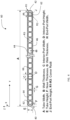
FIG. 4 is a cross-sectional view of aheat exchange tube 60 in an example embodiment. The cross-sectional view ofFIG. 4 depicts theheat exchange tube 60 in the Y-Z plane. Theheat exchange tube 60 includes thefirst nose 40, thesecond nose 42, the firstouter surface 44 and the secondouter surface 46, as shown inFIG. 3 . The ports internal to theheat exchange tube 60 includeend ports 62 that are immediately adjacent to thefirst nose 40 and thesecond nose 42, respectively. Ports located between theend ports 62 are referenced asinterior ports 64. Theinterior ports 64 are separated along the Y axis bywebs 66.FIG. 4 identifies various dimensional references used herein. - The
first nose 40 and/or thesecond nose 42 may be any shape, such as semicircular or flat. The nose thickness, F, of one or both of thefirst nose 40 and thesecond nose 42 may be lower, higher or equal to web thickness, G, ofwebs 66. One or both of theend ports 62 have a generally non-circular, polygonal shape (e.g., rectangular, square). An interior wall of theend port 62 immediately adjacent to theadjacent nose 40/42 has a curvature of zero. The non-circular shape of one or both of theend ports 62 helps reduce peak stresses on theheat exchange tube 60 when subjected to an internal pressure during operation. - In an example embodiment, one or both of the
end ports 62 comprises a foursided polygon with or without rounded corners. Each side of theend port 62 is a straight line with zero curvature. A radius, R2, at one or more interior corners of theend port 62 may be less than 20% of the port minor dimension (e.g., the end port width along the Y axis shown inFIG. 4 ). - All the ports, both end
ports 62 andinterior ports 64, have an aspect ratio defined as width (along the Y axis) divided by height (along the Z axis). The aspect ratio of one or both of theend ports 62 may be smaller, equal or greater than an aspect ratio of one or moreinterior ports 64. In an example embodiment, the aspect ratio of the one or both of theend ports 62 ranges from 0.1 and 10. -
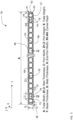
FIG. 5 is a cross-sectional view of aheat exchange tube 70 in an example embodiment. The cross-sectional view ofFIG. 5 depicts theheat exchange tube 70 in the Y-Z plane. Theheat exchange tube 70 includes thefirst nose 40, thesecond nose 42, the firstouter surface 44 and the secondouter surface 46. The ports internal to theheat exchange tube 70 includeend ports 72 that are immediately adjacent to thefirst nose 40 and thesecond nose 42, respectively. Ports located between theend ports 72 include as firstinterior ports 74 and secondinterior ports 76. Theend ports 72, firstinterior ports 74 and secondinterior ports 76 are separated along the Y axis bywebs 66. The firstinterior ports 74 may be immediately adjacent to theend ports 72.FIG. 5 identifies various dimensional references used herein. - In
heat exchange tube 70, one or both of theend ports 72 have a rounded interior wall facing thefirst nose 40 and thesecond nose 42, respectively. The firstinterior ports 74 have differing wall thickness (measured along the Z axis) than the secondinterior ports 76. As shown inFIG. 5 , two firstinterior ports 74 have different wall thickness, B2, as compared to theend ports 72 and the secondinterior ports 76. In one embodiment, the wall thickness (B2) of the firstinterior ports 74 is greater than a wall thickness (B1) of theend ports 72 and the secondinterior ports 76. InFIG. 5 , both the wall thicknesses (B2) from the inside surface of the firstinterior port 74 to the firstouter surface 44 and the inside surface of firstinterior port 74 to the secondouter surface 46 is greater than the wall thickness (B1) of theend ports 72 and the secondinterior ports 76. It is understood that only one of the wall thicknesses (B2) from the inside surface of the firstinterior port 74 to the firstouter surface 44 and the inside surface of the firstinterior port 74 to the secondouter surface 46 may be greater than the wall thickness (B1) of theend ports 72 and the secondinterior ports 76. - Referring to
FIG. 5 , D2=E-2*B2 and D1=E-2*B1, where D2 is a height of a firstinterior port 74 measured along the Z axis, D1 is a height of a secondinterior port 76 measured along the Z axis, E is a height of theheat exchange tube 70 along the Z axis, B2 is a wall thickness of the firstinterior port 74 and B1 is a wall thickness of the secondinterior port 76. In example embodiments, D2 is less than D1, which reduces the maximum principal stress on theheat exchange tube 70 when subjected to an internal working pressure. - A ratio of B2/B1 may range from 1.01 to an upper limit of E/(2B1). In one example embodiment, the ratio of B2/B1ranges from 1.1 to 1.5.
- An aspect ratio (AR) of the first
interior ports 74 may be different than an aspect ratio of the secondinterior ports 76. In one embodiment, the aspect ratio of one or both of the firstinterior ports 74 is greater than the aspect ratio of theend ports 72 and the aspect ratio of the secondinterior ports 76. Also, the aspect ratio of one or both of theend ports 72 is less than that of the secondinterior ports 76. The aspect ratio of the firstinterior ports 74 is higher than that of the secondinterior ports 76. This may be summarized as ARend-port 72 < ARint-port 76 < ARint-port 74. -
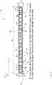
FIG. 6 is a cross-sectional view of aheat exchange tube 80 in an example embodiment. The cross-sectional view ofFIG. 6 depicts theheat exchange tube 80 in the Y-Z plane.Heat exchange tube 80 is similar to heatexchange tube 70 ofFIG. 5 , with the difference being that more of the interior ports are firstinterior ports 74. As shown inFIG. 6 , the firstinterior ports 74, having a greater wall thickness along the Z axis, are located not only adjacent to theend ports 72, but also in the interior of theheat exchange tube 80. InFIG. 6 , a firstinterior port 74 is positioned after every two secondinterior ports 76. It is understood that the placement of the firstinterior ports 74 relative to the secondinterior ports 76 may be varied. This pattern of a firstinterior port 74 followed by two secondinterior ports 76 further reduces peak stresses on theheat exchange tube 80. -
FIG. 7 is a cross-sectional view of aheat exchange tube 90 in an example embodiment. The cross-sectional view ofFIG. 7 depicts theheat exchange tube 90 in the Y-Z plane.FIG. 7 combines elements ofFIG. 4 andFIG. 6 . - The
end ports 62 have a generally non-circular, polygonal shape (e.g., rectangular, square) as described with reference toFIG. 4 . Theheat exchange tube 90 includes firstinterior ports 74 interspersed with the secondinterior ports 76 as described with reference toFIG. 6 . - The dimensions of the embodiments of
FIGs. 4-7 may follow certain relationships with respect to each other, are presented in Table 1 below. The dimensions are normalized with respect to dimension E, the height of the heat exchange tube along the Z axis.TABLE 1 Dimension Adjusted Ratio (full range) Ratios (example range) Min Max Min Max A 4 40 10 20 B1 0.05 0.50 0.1 0.25 B2 0.05 0.50 0.1 0.3 C 0.10 5.00 0.5 2.0 D1 0.05 3.00 0.05 1.5 D2 0.05 3.00 0.05 1.5 E Normalization parameter F 0.05 2.00 0.05 1.0 G 0.02 0.75 0.05 0.3 H 0.05 5.00 0.1 2 J 0.05 4.00 0.05 1.5 R1 0.10 2.00 0.25 0.75 R2 0.01 0.25 0.02 0.1 R3 0.01 0.25 0.02 0.1 -
FIG. 8 is a cross-sectional view of aheat exchange tube 100 in an example embodiment. The cross-sectional view ofFIG. 8 depicts theheat exchange tube 100 in the Y-Z plane. Inheat exchange tube 100, one or both of theend ports 72 have a rounded interior wall facing thefirst nose 40 and thesecond nose 42, respectively, as described above with reference toFIG. 5 . Theinterior ports 84 have a different construction than the ports inFIGs. 4-7 . Theinterior ports 84 are positioned along the Y-axis between theend ports 72. Theinterior ports 84 include at least one wall having a wall thickness that varies over a width of theinterior port 84. The varying wall thickness, B, creates a narrowed passage or throat at a distance, K, from an interior wall of theinterior port 84 measured along the Y axis. An interior port height (variable D) ranges from a minimum D2 to a maximum D1. Theinterior port 84 height varies from the maximum D1, to the minimum D2 and back to the maximum D1, along the widthwise direction of the interior port 84 (i.e., along the Y axis). In the embodiment shown inFIG. 8 , the interior surface of theinterior port 84 is V-shaped or chevroned, such that theinterior port 84 height decreases linearly to a minimum, D2, and then increases linearly to a maximum, D1, as measured along the widthwise direction of the interior port 84 (i.e., along the Y axis). The interior surface of theinterior port 84 may follow other contours, such as an arc. - The
interior ports 84 may have a symmetric or asymmetric throat. In other words, the minimum height, D2, in the interior ofinterior port 84 does not need to be in the center of the interior port 84 (e.g., dimension D2 is not at middle of dimension "C" i.e., K≠C/2). The dimensions ofFIG. 8 may follow the following relationships. - K=0.1xC to 0.9xC (example range is 0.4xC to 0.6xC)
- D2=0.1xD1 to 0.98xD1 where, D1=E-2xB (example range is 0.65xD1 to 0.85xD1)
- The dimensions of the embodiments of
FIG. 8 may follow certain relationships with respect to each other, are presented in Table 2 below. The majority of the dimensions are normalized with respect to dimension E, the height of the heat exchange tube along the Z axis. Dimension D2 is represented as a fraction of D1, and not normalized by dimension E. Dimension K is represented as a fraction of C, and not normalized by dimension E.TABLE 2 Dimension Adjusted Ratio (full range) Ratios (example range) Min Max Min Max A 4 40 10 20 B1 0.05 0.50 0.1 0.25 C 0.10 5.00 0.5 2.0 D1 0.05 3.00 0.05 1.5 D2 0.1*D1 0.98*D1 0.65*D1 0.85*D1 E Normalization parameter F 0.05 2.00 0.05 1.0 G 0.02 0.75 0.05 0.3 H 0.05 5.00 0.1 2 J 0.05 4.00 0.05 1.5 K 0.1*C 0.9*C 0.3*C 0.6*C R1 0.10 2.00 0.25 0.75 R2 0.01 0.25 0.02 0.1 R3 0.01 0.25 0.02 0.1 -
FIG. 9 depicts pressure forces on walls of theinterior port 84 in an example embodiment. Due to the V-shaped interior surface of theinterior port 84, horizontal components of the resolved pressure forces (i.e., forces along the Y axis) on either side of the V-shaped walls cancel each other. As a result, only the vertical components of the internal pressure forces are relevant for generating hoop stresses in the port walls. The vertical component being lower than the original pressure forces, it results in lower stresses in the tube. -
FIG. 10 is a cross-sectional view of aheat exchange tube 110 in an example embodiment. The cross-sectional view ofFIG. 10 depicts theheat exchange tube 110 in the Y-Z plane. Inheat exchange tube 110, one or both of theend ports 62 have a generally non-circular, polygonal shape (e.g., rectangular, square) as described above with reference toFIG. 4 . Theinterior ports 84 have the same construction as described with reference toFIG. 8 . The dimensions of the embodiments ofFIG. 10 may follow certain relationships with respect to each other, are presented in Table 2 above. - Embodiments disclosed herein provide heat exchange tubes using less material than existing designs while will still meeting burst strength requirements.
- Dimensions used in this application are intended to include the recited dimension and normal variances due to manufacturing tolerances, measurement tolerances, etc.
- The terminology used herein is for the purpose of describing particular embodiments only and is not intended to be limiting of the invention. As used herein, the singular forms "a", "an" and "the" are intended to include the plural forms as well, unless the context clearly indicates otherwise. It will be further understood that the terms "comprises" and/or "comprising," when used in this specification, specify the presence of stated features, integers, steps, operations, elements, and/or components, but do not preclude the presence or addition of one or more other features, integers, steps, operations, element components, and/or groups thereof.
- While the invention has been described with reference to an exemplary embodiment or embodiments, it will be understood by those skilled in the art that various changes may be made and equivalents may be substituted for elements thereof without departing from the scope of the invention as set out in the appended claims. In addition, many modifications may be made to adapt a particular situation or material to the teachings of the invention without departing from the essential scope thereof. Therefore, it is intended that the invention not be limited to the particular embodiment disclosed as the best mode contemplated for carrying out this invention, but that the invention will include all embodiments falling within the scope of the claims.
- The following clauses set out aspects of the invention that may or may not presently be claimed, but which may form the basis for future amendment or a divisional application.
- 1. A heat exchange tube (100, 110) for use in a heat exchanger, the heat exchange tube (100, 110) comprising:
- a first nose (40) and a second nose (42) aligned on a Y axis along a width of the heat exchange tube (100, 110); and
- a port (84) positioned between the first nose (40) and the second nose (42), the port (84) having an interior port height along a Z axis perpendicular to the Y axis;
- wherein the interior port height varies along the Y axis to define a throat in the port.
- 2. The heat exchange tube (100, 110) of clause 1, wherein the interior port height (D) increases and decreases along the Y axis.
- 3. The heat exchange tube (100, 110) of clause 2, wherein an interior surface of the port (84) is V-shaped.
- 4. The heat exchange tube (100, 110) of clause 2, wherein an interior surface of the port is curved.
- 5. The heat exchange tube (100, 110) of any preceding clause, wherein the interior port height has a minimum at a center of the port as measured along the Y axis.
- 6. The heat exchange tube (100, 110) of any of clauses 1 to 4, wherein the interior port height has a minimum offset from a center of the port as measured along the Y axis.
- 7. The heat exchange tube (100, 110) of any preceding clause, wherein the port (84) has a width, C, measured along the Y axis and the interior port height has a minimum at a distance K from a from a side wall of the port, where K ranges from 0.1xC to 0.9xC.
- 8. The heat exchange tube (100, 110) of
clause 7, wherein K ranges from 0.4xC to 0.6xC. - 9. The heat exchange tube (100, 110) of any preceding clause, wherein interior port height has a maximum of D1 and a minimum of D2, wherein D2 ranges from 0.1xD1 to 0.98xD1.
- 10. The heat exchange tube (100, 110) of clause 9, wherein D2 ranges from 0.65xD1 to 0.85xD1.
- 11. A heat exchanger (30) including a heat exchange tube (100, 110) as recited in any preceding clause.
Claims (12)
- A heat exchange tube (60, 90, 110) for use in a heat exchanger, the heat exchange tube (60, 90, 110) comprising:a first nose (40) and a second nose (42) aligned on an axis along a width (A) of the heat exchange tube (60, 90, 110);an end port (62) immediately adjacent to the first nose (40);wherein the end port has a non-circular, polygonal shape.
- The heat exchange tube (60, 90, 110) of claim 1, wherein the end port (62) is rectangular.
- The heat exchange tube (60, 90, 110) of claim 1 or 2, wherein an interior side of the end port (62) immediately adjacent to the first nose (40) has a curvature of zero.
- The heat exchange tube (60, 90, 110) of claim 1, 2 or 3, wherein the end port (62) has an aspect ratio of width (H) to height (J) ranging from 0.1 to 10.
- A heat exchange tube (70, 80, 90) for use in a heat exchanger (30), the heat exchange tube (70, 80, 90) comprising:a first nose (40) and a second nose (42) aligned on a Y axis along a width (A) of the heat exchange tube (60, 90, 110);an end port (62) immediately adjacent to the first nose (40);a first interior port (74) positioned between the first nose (40) and the second nose (42);a second interior port (76) positioned between the first nose (40) and the second nose (42);the first interior port (74) having a wall having a first thickness, B2, along a Z axis perpendicular to the Y axis;the second interior port (76) having a wall having a second thickness, B1, along the Z axis;wherein the first thickness is greater than the second thickness.
- The heat exchange tube (70, 80, 90) of claim 5, wherein the first interior port (74) is immediately adjacent to the end port (62).
- The heat exchange tube (70, 80, 90) of claim 5 or 6, further comprising a further first interior port (74), the further first interior port having a wall having the first thickness, B2, along the Z axis.
- The heat exchange tube (70, 80, 90) of claim 7, wherein the first interior port (74) and the further first interior port (74) are positioned on opposite sides of the second interior port (76) along the Y axis.
- The heat exchange tube (70, 80, 90) of claim 7 or 8, further comprising a further second interior port (76), the further second interior port (76) having a wall having the second thickness, B1, along the Z axis.
- The heat exchange tube (70, 80, 90) of claim 9, wherein the first interior port (74), the second interior port (76), the further second interior port (74) and the further first interior port (76) are arranged in sequence along the Y axis.
- The heat exchange tube (70, 80, 90) of claim 5, wherein a ratio of B2/B1 ranges from 1.01 to E/(2B1), where E is a height of the heat exchange tube (70, 80, 90) along the Z axis.
- The heat exchange tube (70, 80, 90) of claim 11, wherein a ratio of B2/B1 ranges from 1.1 to 1.5.
Applications Claiming Priority (2)
| Application Number | Priority Date | Filing Date | Title |
|---|---|---|---|
| US202163162332P | 2021-03-17 | 2021-03-17 | |
| EP22162563.5A EP4060275B1 (en) | 2021-03-17 | 2022-03-16 | Microchannel heat exchanger |
Related Parent Applications (2)
| Application Number | Title | Priority Date | Filing Date |
|---|---|---|---|
| EP22162563.5A Division-Into EP4060275B1 (en) | 2021-03-17 | 2022-03-16 | Microchannel heat exchanger |
| EP22162563.5A Division EP4060275B1 (en) | 2021-03-17 | 2022-03-16 | Microchannel heat exchanger |
Publications (2)
| Publication Number | Publication Date |
|---|---|
| EP4549866A2 true EP4549866A2 (en) | 2025-05-07 |
| EP4549866A3 EP4549866A3 (en) | 2025-08-20 |
Family
ID=80785154
Family Applications (2)
| Application Number | Title | Priority Date | Filing Date |
|---|---|---|---|
| EP22162563.5A Active EP4060275B1 (en) | 2021-03-17 | 2022-03-16 | Microchannel heat exchanger |
| EP25160668.7A Pending EP4549866A3 (en) | 2021-03-17 | 2022-03-16 | Microchannel heat exchanger |
Family Applications Before (1)
| Application Number | Title | Priority Date | Filing Date |
|---|---|---|---|
| EP22162563.5A Active EP4060275B1 (en) | 2021-03-17 | 2022-03-16 | Microchannel heat exchanger |
Country Status (3)
| Country | Link |
|---|---|
| US (1) | US12111120B2 (en) |
| EP (2) | EP4060275B1 (en) |
| CN (1) | CN115111953A (en) |
Family Cites Families (22)
| Publication number | Priority date | Publication date | Assignee | Title |
|---|---|---|---|---|
| US4497363A (en) | 1982-04-28 | 1985-02-05 | Heronemus William E | Plate-pin panel heat exchanger and panel components therefor |
| JPS59129392A (en) * | 1983-01-10 | 1984-07-25 | Nippon Denso Co Ltd | Heat exchanger |
| JPH06185885A (en) | 1992-07-24 | 1994-07-08 | Furukawa Electric Co Ltd:The | Flat multi-hole condensing heat transfer tube |
| JPH06300473A (en) | 1993-04-19 | 1994-10-28 | Sanden Corp | Flat refrigerant pipe |
| US5941303A (en) * | 1997-11-04 | 1999-08-24 | Thermal Components | Extruded manifold with multiple passages and cross-counterflow heat exchanger incorporating same |
| KR100382523B1 (en) * | 2000-12-01 | 2003-05-09 | 엘지전자 주식회사 | a tube structure of a micro-multi channel heat exchanger |
| KR100518856B1 (en) * | 2003-09-04 | 2005-09-30 | 엘지전자 주식회사 | Heat exchanger of flat tube |
| US8776874B2 (en) * | 2007-12-30 | 2014-07-15 | Valeo, Inc. | Heat exchanger tubes and methods for enhancing thermal performance and reducing flow passage plugging |
| US8234881B2 (en) * | 2008-08-28 | 2012-08-07 | Johnson Controls Technology Company | Multichannel heat exchanger with dissimilar flow |
| US20120227945A1 (en) * | 2009-09-16 | 2012-09-13 | Carrier Corporation | Free-draining finned surface architecture for heat exchanger |
| US20130153174A1 (en) * | 2010-08-24 | 2013-06-20 | Carrier Corporation | Microchannel heat exchanger fin |
| JP5257485B2 (en) * | 2011-05-13 | 2013-08-07 | ダイキン工業株式会社 | Heat exchanger |
| WO2013160956A1 (en) * | 2012-04-26 | 2013-10-31 | 三菱電機株式会社 | Heat-exchanger header and heat exchanger provided therewith |
| JP2014001868A (en) | 2012-06-15 | 2014-01-09 | Sanden Corp | Heat exchanger |
| US20150153116A1 (en) * | 2012-07-27 | 2015-06-04 | Kyocera Corporation | Flow path member, and heat exchanger and semiconductor manufacturing device using same |
| KR102634151B1 (en) * | 2015-10-29 | 2024-02-06 | 가부시키가이샤 유에이씨제이 | Aluminum extruded flat perforated tube and heat exchanger |
| JP6636110B1 (en) * | 2018-09-13 | 2020-01-29 | 日立ジョンソンコントロールズ空調株式会社 | Air conditioner equipped with heat exchanger, pipe expansion member, and heat exchanger |
| EP3786565B1 (en) * | 2019-05-05 | 2022-08-31 | Hangzhou Sanhua Research Institute Co., Ltd. | Microchannel flat tube and microchannel heat exchanger |
| CN111895839B (en) * | 2019-05-05 | 2021-09-21 | 浙江三花智能控制股份有限公司 | Micro-channel flat tube and micro-channel heat exchanger |
| US11236946B2 (en) | 2019-05-10 | 2022-02-01 | Carrier Corporation | Microchannel heat exchanger |
| CN112444146B (en) * | 2019-08-29 | 2024-08-20 | 青岛海信日立空调系统有限公司 | Microchannel heat exchanger and air conditioner |
| US11592244B2 (en) * | 2020-02-20 | 2023-02-28 | Carrier Corporation | Multiport fluid distributor and microchannel heat exchanger having the same |
-
2022
- 2022-02-17 US US17/674,193 patent/US12111120B2/en active Active
- 2022-03-16 EP EP22162563.5A patent/EP4060275B1/en active Active
- 2022-03-16 EP EP25160668.7A patent/EP4549866A3/en active Pending
- 2022-03-16 CN CN202210261186.0A patent/CN115111953A/en active Pending
Also Published As
| Publication number | Publication date |
|---|---|
| EP4060275B1 (en) | 2025-04-23 |
| EP4549866A3 (en) | 2025-08-20 |
| EP4060275A1 (en) | 2022-09-21 |
| US12111120B2 (en) | 2024-10-08 |
| US20220299272A1 (en) | 2022-09-22 |
| CN115111953A (en) | 2022-09-27 |
Similar Documents
| Publication | Publication Date | Title |
|---|---|---|
| AU2012208123B2 (en) | Heat exchanger and air conditioner | |
| US10508862B2 (en) | Heat exchanger for air-cooled chiller | |
| US7073570B2 (en) | Automotive heat exchanger | |
| US20130240186A1 (en) | Multiple Tube Bank Flattened Tube Finned Heat Exchanger | |
| US20090065183A1 (en) | Flat heat transfer tube | |
| US10378833B2 (en) | Stacking-type header, heat exchanger, and air-conditioning apparatus | |
| AU2012208118A1 (en) | Heat exchanger and air conditioner | |
| US20120031601A1 (en) | Multichannel tubes with deformable webs | |
| CA2596364A1 (en) | Parallel flow heat exchanger with crimped channel entrance | |
| US10514204B2 (en) | Multiport extruded heat exchanger | |
| CN110651162B (en) | Refrigerant evaporator and method for manufacturing same | |
| US20240085122A1 (en) | Heat exchanger and refrigeration cycle apparatus | |
| CN107110568A (en) | The collapsible micro-channel heat exchanger of many plates of multi-path | |
| US12130057B2 (en) | Heat exchanger, outdoor unit, and refrigeration cycle device | |
| CN108474630A (en) | Aluminum extruded flat perforated tubes and heat exchangers | |
| JP3911604B2 (en) | Heat exchanger and refrigeration cycle | |
| US11236946B2 (en) | Microchannel heat exchanger | |
| CN112888911B (en) | Heat exchanger and air conditioner | |
| EP4060275A1 (en) | Microchannel heat exchanger | |
| AU2019460046A1 (en) | Heat exchanger and refrigeration cycle apparatus | |
| WO2023199400A1 (en) | Heat exchanger and refrigeration cycle device | |
| CN115698617A (en) | Heat exchanger and air conditioner using same | |
| JP2003222436A (en) | Heat exchanger for heat pump type air conditioner | |
| US20190024954A1 (en) | Heat Exchange System | |
| US20210239412A1 (en) | Expansion assembly for heat exchanger |
Legal Events
| Date | Code | Title | Description |
|---|---|---|---|
| PUAI | Public reference made under article 153(3) epc to a published international application that has entered the european phase |
Free format text: ORIGINAL CODE: 0009012 |
|
| STAA | Information on the status of an ep patent application or granted ep patent |
Free format text: STATUS: THE APPLICATION HAS BEEN PUBLISHED |
|
| AC | Divisional application: reference to earlier application |
Ref document number: 4060275 Country of ref document: EP Kind code of ref document: P |
|
| AK | Designated contracting states |
Kind code of ref document: A2 Designated state(s): AL AT BE BG CH CY CZ DE DK EE ES FI FR GB GR HR HU IE IS IT LI LT LU LV MC MK MT NL NO PL PT RO RS SE SI SK SM TR |
|
| PUAL | Search report despatched |
Free format text: ORIGINAL CODE: 0009013 |
|
| AK | Designated contracting states |
Kind code of ref document: A3 Designated state(s): AL AT BE BG CH CY CZ DE DK EE ES FI FR GB GR HR HU IE IS IT LI LT LU LV MC MK MT NL NO PL PT RO RS SE SI SK SM TR |
|
| RIC1 | Information provided on ipc code assigned before grant |
Ipc: F28F 1/02 20060101AFI20250715BHEP |
|
| STAA | Information on the status of an ep patent application or granted ep patent |
Free format text: STATUS: REQUEST FOR EXAMINATION WAS MADE |
|
| 17P | Request for examination filed |
Effective date: 20260213 |
|
| GRAP | Despatch of communication of intention to grant a patent |
Free format text: ORIGINAL CODE: EPIDOSNIGR1 |
|
| STAA | Information on the status of an ep patent application or granted ep patent |
Free format text: STATUS: GRANT OF PATENT IS INTENDED |