EP4549865A1 - Battery cooling system and method for operating a battery cooling system - Google Patents
Battery cooling system and method for operating a battery cooling system Download PDFInfo
- Publication number
- EP4549865A1 EP4549865A1 EP23217379.9A EP23217379A EP4549865A1 EP 4549865 A1 EP4549865 A1 EP 4549865A1 EP 23217379 A EP23217379 A EP 23217379A EP 4549865 A1 EP4549865 A1 EP 4549865A1
- Authority
- EP
- European Patent Office
- Prior art keywords
- coolant
- channels
- battery
- heat exchanger
- vehicle
- Prior art date
- Legal status (The legal status is an assumption and is not a legal conclusion. Google has not performed a legal analysis and makes no representation as to the accuracy of the status listed.)
- Pending
Links
Images




Classifications
-
- H—ELECTRICITY
- H01—ELECTRIC ELEMENTS
- H01M—PROCESSES OR MEANS, e.g. BATTERIES, FOR THE DIRECT CONVERSION OF CHEMICAL ENERGY INTO ELECTRICAL ENERGY
- H01M10/00—Secondary cells; Manufacture thereof
- H01M10/60—Heating or cooling; Temperature control
- H01M10/65—Means for temperature control structurally associated with the cells
- H01M10/656—Means for temperature control structurally associated with the cells characterised by the type of heat-exchange fluid
- H01M10/6567—Liquids
- H01M10/6568—Liquids characterised by flow circuits, e.g. loops, located externally to the cells or cell casings
-
- F—MECHANICAL ENGINEERING; LIGHTING; HEATING; WEAPONS; BLASTING
- F28—HEAT EXCHANGE IN GENERAL
- F28D—HEAT-EXCHANGE APPARATUS, NOT PROVIDED FOR IN ANOTHER SUBCLASS, IN WHICH THE HEAT-EXCHANGE MEDIA DO NOT COME INTO DIRECT CONTACT
- F28D7/00—Heat-exchange apparatus having stationary tubular conduit assemblies for both heat-exchange media, the media being in contact with different sides of a conduit wall
- F28D7/0008—Heat-exchange apparatus having stationary tubular conduit assemblies for both heat-exchange media, the media being in contact with different sides of a conduit wall the conduits for one medium being in heat conductive contact with the conduits for the other medium
-
- F—MECHANICAL ENGINEERING; LIGHTING; HEATING; WEAPONS; BLASTING
- F28—HEAT EXCHANGE IN GENERAL
- F28D—HEAT-EXCHANGE APPARATUS, NOT PROVIDED FOR IN ANOTHER SUBCLASS, IN WHICH THE HEAT-EXCHANGE MEDIA DO NOT COME INTO DIRECT CONTACT
- F28D9/00—Heat-exchange apparatus having stationary plate-like or laminated conduit assemblies for both heat-exchange media, the media being in contact with different sides of a conduit wall
- F28D9/0031—Heat-exchange apparatus having stationary plate-like or laminated conduit assemblies for both heat-exchange media, the media being in contact with different sides of a conduit wall the conduits for one heat-exchange medium being formed by paired plates touching each other
- F28D9/0037—Heat-exchange apparatus having stationary plate-like or laminated conduit assemblies for both heat-exchange media, the media being in contact with different sides of a conduit wall the conduits for one heat-exchange medium being formed by paired plates touching each other the conduits for the other heat-exchange medium also being formed by paired plates touching each other
-
- H—ELECTRICITY
- H01—ELECTRIC ELEMENTS
- H01M—PROCESSES OR MEANS, e.g. BATTERIES, FOR THE DIRECT CONVERSION OF CHEMICAL ENERGY INTO ELECTRICAL ENERGY
- H01M10/00—Secondary cells; Manufacture thereof
- H01M10/42—Methods or arrangements for servicing or maintenance of secondary cells or secondary half-cells
- H01M10/425—Structural combination with electronic components, e.g. electronic circuits integrated to the outside of the casing
-
- H—ELECTRICITY
- H01—ELECTRIC ELEMENTS
- H01M—PROCESSES OR MEANS, e.g. BATTERIES, FOR THE DIRECT CONVERSION OF CHEMICAL ENERGY INTO ELECTRICAL ENERGY
- H01M10/00—Secondary cells; Manufacture thereof
- H01M10/60—Heating or cooling; Temperature control
-
- H—ELECTRICITY
- H01—ELECTRIC ELEMENTS
- H01M—PROCESSES OR MEANS, e.g. BATTERIES, FOR THE DIRECT CONVERSION OF CHEMICAL ENERGY INTO ELECTRICAL ENERGY
- H01M10/00—Secondary cells; Manufacture thereof
- H01M10/60—Heating or cooling; Temperature control
- H01M10/61—Types of temperature control
- H01M10/613—Cooling or keeping cold
-
- H—ELECTRICITY
- H01—ELECTRIC ELEMENTS
- H01M—PROCESSES OR MEANS, e.g. BATTERIES, FOR THE DIRECT CONVERSION OF CHEMICAL ENERGY INTO ELECTRICAL ENERGY
- H01M10/00—Secondary cells; Manufacture thereof
- H01M10/60—Heating or cooling; Temperature control
- H01M10/62—Heating or cooling; Temperature control specially adapted for specific applications
- H01M10/625—Vehicles
-
- H—ELECTRICITY
- H01—ELECTRIC ELEMENTS
- H01M—PROCESSES OR MEANS, e.g. BATTERIES, FOR THE DIRECT CONVERSION OF CHEMICAL ENERGY INTO ELECTRICAL ENERGY
- H01M10/00—Secondary cells; Manufacture thereof
- H01M10/60—Heating or cooling; Temperature control
- H01M10/63—Control systems
- H01M10/633—Control systems characterised by algorithms, flow charts, software details or the like
-
- H—ELECTRICITY
- H01—ELECTRIC ELEMENTS
- H01M—PROCESSES OR MEANS, e.g. BATTERIES, FOR THE DIRECT CONVERSION OF CHEMICAL ENERGY INTO ELECTRICAL ENERGY
- H01M10/00—Secondary cells; Manufacture thereof
- H01M10/60—Heating or cooling; Temperature control
- H01M10/65—Means for temperature control structurally associated with the cells
- H01M10/655—Solid structures for heat exchange or heat conduction
- H01M10/6551—Surfaces specially adapted for heat dissipation or radiation, e.g. fins or coatings
-
- H—ELECTRICITY
- H01—ELECTRIC ELEMENTS
- H01M—PROCESSES OR MEANS, e.g. BATTERIES, FOR THE DIRECT CONVERSION OF CHEMICAL ENERGY INTO ELECTRICAL ENERGY
- H01M10/00—Secondary cells; Manufacture thereof
- H01M10/60—Heating or cooling; Temperature control
- H01M10/65—Means for temperature control structurally associated with the cells
- H01M10/655—Solid structures for heat exchange or heat conduction
- H01M10/6556—Solid parts with flow channel passages or pipes for heat exchange
-
- F—MECHANICAL ENGINEERING; LIGHTING; HEATING; WEAPONS; BLASTING
- F28—HEAT EXCHANGE IN GENERAL
- F28F—DETAILS OF HEAT-EXCHANGE AND HEAT-TRANSFER APPARATUS, OF GENERAL APPLICATION
- F28F3/00—Plate-like or laminated elements; Assemblies of plate-like or laminated elements
- F28F3/02—Elements or assemblies thereof with means for increasing heat-transfer area, e.g. with fins, with recesses, with corrugations
- F28F3/025—Elements or assemblies thereof with means for increasing heat-transfer area, e.g. with fins, with recesses, with corrugations the means being corrugated, plate-like elements
-
- H—ELECTRICITY
- H01—ELECTRIC ELEMENTS
- H01M—PROCESSES OR MEANS, e.g. BATTERIES, FOR THE DIRECT CONVERSION OF CHEMICAL ENERGY INTO ELECTRICAL ENERGY
- H01M10/00—Secondary cells; Manufacture thereof
- H01M10/42—Methods or arrangements for servicing or maintenance of secondary cells or secondary half-cells
- H01M10/425—Structural combination with electronic components, e.g. electronic circuits integrated to the outside of the casing
- H01M2010/4271—Battery management systems including electronic circuits, e.g. control of current or voltage to keep battery in healthy state, cell balancing
-
- H—ELECTRICITY
- H01—ELECTRIC ELEMENTS
- H01M—PROCESSES OR MEANS, e.g. BATTERIES, FOR THE DIRECT CONVERSION OF CHEMICAL ENERGY INTO ELECTRICAL ENERGY
- H01M2220/00—Batteries for particular applications
- H01M2220/20—Batteries in motive systems, e.g. vehicle, ship, plane
-
- Y—GENERAL TAGGING OF NEW TECHNOLOGICAL DEVELOPMENTS; GENERAL TAGGING OF CROSS-SECTIONAL TECHNOLOGIES SPANNING OVER SEVERAL SECTIONS OF THE IPC; TECHNICAL SUBJECTS COVERED BY FORMER USPC CROSS-REFERENCE ART COLLECTIONS [XRACs] AND DIGESTS
- Y02—TECHNOLOGIES OR APPLICATIONS FOR MITIGATION OR ADAPTATION AGAINST CLIMATE CHANGE
- Y02E—REDUCTION OF GREENHOUSE GAS [GHG] EMISSIONS, RELATED TO ENERGY GENERATION, TRANSMISSION OR DISTRIBUTION
- Y02E60/00—Enabling technologies; Technologies with a potential or indirect contribution to GHG emissions mitigation
- Y02E60/10—Energy storage using batteries
Definitions
- the present invention generally relates to a battery cooling system for a vehicle battery unit and a method for operating such a battery cooling system, and, in particular embodiments, to a battery cooling system for an aeronautic vehicle.
- a heat exchanger in accordance with an embodiment, includes a base body, cooling fins protruding from a first side of the base body, first channels integrated in the base body and connected to a first connector and a second connector, the first channels configured to guide a first coolant and second channels integrated in the base body and connected to a first connector and a second connector, the second channels configured to guide a second coolant, wherein the first channels are separate from the second channels and wherein the heat exchanger is capable of being integrated in an outside surface of a vehicle.
- a vehicle in accordance with a further embodiment includes a battery temperature control system comprising a battery pack and a battery management system in connection with the battery temperature control system and configured to operate the battery temperature control system in a first cooling mode when a temperature of the battery is above a first predetermined temperature, the first mode configured to cool a coolant, to operate the battery temperature control system in a second cooling mode when the temperature of the battery is above a second predetermined temperature, the second mode configured to cool the coolant, to operate the battery temperature control system in a third heating mode when the temperature of the battery is below a third predetermined temperature, the third mode configured to heat the coolant and to operate the battery temperature control system in a fourth idle mode when the temperature of the battery is between the first predetermined temperature or the second predetermined temperature and the third predetermined temperature.
- Embodiments provide a boom integrated heat exchanger for an aviation vehicle. Further embodiments provide a heat exchanger configured to provide coolant-to-coolant cooling and/or heating, and air-to-coolant cooling for a vehicle battery unit or vehicle energy storage unit.
- the heat exchanger may provide three different functionalities: 1) cooling the battery (unit) when the aviation vehicle is airborne; 2) cooling the battery (unit) when the aviation vehicle is on ground or parked and battery (unit) temperature is elevated above a predetermined temperature in order to, e.g., precondition the battery (unit) for safe take off; and 3) heating the battery (unit) when the aviation vehicle is on ground or parked and battery (unit) temperature is below a predetermined temperature in order to, e.g., precondition the battery (unit) for efficient electrical charging.
- FIG. 1 shows a block diagram of a battery temperature control system 10 for a vehicle battery unit 1.
- the related vehicle may be an aviation vehicle such as an aircraft or a drone.
- the aviation vehicle may be a vertical take-off and landing (VTOL) vehicle and the vehicle battery unit 1 may provide power to a vehicle engine unit that is (or is part of) a vertical thrust unit (VTU).
- VTU vertical thrust unit
- the battery temperature control system 10 comprises a direct battery temperature control system 20 and a ground temperature control system 30.
- the vehicle battery unit 1 as shown in Figure 1 may be a vehicle battery unit 1 for a single vehicle engine unit/VTU and in particular for a motor controller of an electric motor and/or electric motor.
- the direct battery temperature control system 20 comprises a heat exchanger 40, a device 50 configured to move the coolant (e.g., electric pump), a battery (pack) 60 and first coolant lines 21.
- the components 40-60 of the direct battery temperature control system 20 may be independent and distinct and are connected by the first coolant lines 21.
- the first coolant lines 21 may directly connect the components 40-60 to each other.
- the system 20 with the first coolant lines 21 may form a closed battery cooling circuit or closed battery cooling loop.
- the electric pump 50 moves or circulates the first coolant through the closed battery cooling circuit or loop.
- the components 40-60 may be arranged in a different order or may include additional components.
- a single first coolant line 21 connects an element 40-60 to another element 40-60.
- multiple first coolant lines 21 can connect one element 40-60 to another element 40-60.
- the ground temperature control system 30 may comprise the heat exchanger 40, outside connectors 80 arranged at an outside surface of the vehicle 2 and second coolant lines 31.
- the second coolant lines 31 may directly connect the heat exchanger 40 to the outside connectors 80.
- the outside connectors 80 may be connectable to a ground support equipment 100.
- the ground support equipment 100 (sometimes also referred to as on-ground chiller) may be configured to provide warm or hot coolant in order to warm up the vehicle battery unit 1 (and in particular the battery (pack) 60) or cold coolant in order to cool the vehicle battery unit 1 (and especially the battery (pack) 60).
- the ground temperature control system 30 together with the connected ground support equipment 100 may form a closed cooling circuit or loop and/or a closed heating circuit or loop for the vehicle battery unit 1.
- the ground support equipment 100 comprises the pump configured to move the second coolant in the closed cooling or heating circuit. In various other embodiments such a pump is integrated in the ground temperature control system 30.
- two (e.g., more than one), three (e.g., more than two), four (e.g., more than three) or six (e.g., more than five) heat exchangers and related coolant lines are connected to one single pair of outside connectors 80 arranged at an outside (side) surface of a boom meaning at least two heat exchangers are connected via second coolant lines 31.
- one second coolant line 31 connects the heat exchanger 40 to a first outside connector 82 and another second coolant line 31 connects the heat exchanger 40 to a second outside connector 84.
- more than one second coolant line 31 can connect the outside connectors 82, 84 to the heat exchanger 40, respectively.
- the first and second coolant lines 21, 31 may be flexible, semiflexible, or hard tubes or pipes. They might be made of plastic, rubber, silicone, or a combination thereof. Alternatively, they are made from metal such as aluminum.
- the first coolant lines 21 of the direct battery temperature control system 20 and the second coolant lines 31 of the ground temperature control system 30 are two different and independent systems and do not intersect so that the first coolant in the system 20 cannot flow to the ground temperature control system 30 or can mix with the second coolant of the second system.
- second coolant i.e., it cannot flow into the first coolant system or mix with the first coolant.
- the systems are two independent systems, which are thermally connected via the heat exchanger 40.
- the heat exchanger 40 comprises and integrates an air-to-coolant (e.g. air-to-liquid) type heat exchanger and a coolant-to-coolant (liquid-to-liquid) type heat exchanger.
- the air-to-coolant type heat exchanger includes cooling fins 440 and first channels (part of the direct battery temperature control system 20) and the coolant-to-coolant type heat exchanger includes second channels (as part of the ground temperature control system 30) and the first channels.
- the first coolant in the first channels is cooled when the aviation vehicle moves, e.g., when it is airborne and air moves over the cooling fins 440.
- first coolant inside the first channels may also be cooled when a second coolant moving inside the second channels (sometimes also called cooling chambers) cools the first coolant in the first cooling channel via thermal exchange.
- first coolant in the first channels may be heated when a second coolant moving in the second channels heats the first coolant in the first cooling channel via thermal exchange.
- the heat exchanger 40 may have a first input 452 to which a first coolant line 21 is connectable and a first output 454 to which another first coolant line 21 is connectable.
- the heat exchanger 40 may comprise a second input 462 to which a second coolant line 31 is connectable and a second output 464 to which another second coolant line 31 is connectable.
- the heat exchanger 40 comprises a heat sink having the cooling fins 440.
- the device 50 configured to move the coolant might be a pump such as an electric pump.
- the operation of the pump 50 may be regulated so that the battery (pack) 60 is not subcooled below a predetermined temperature or heated above another predetermined temperature.
- the operation of the pump 50 may be controlled by a battery management system (BMS) such as a processor or a controller 70.
- BMS battery management system
- the device 50 may have an input to which a first coolant line 21 is connectable and an output to which another first coolant line 21 is connectable.
- the battery or battery pack 60 may comprises battery cells (e.g., pouch cells or cylindrical cells), an internal thermal conditioning system (i.e., coolant channels of the battery), at least one sensor 64, and a battery management system (BMS) 70.
- the temperature of the battery (pack) 60 may be measured with the at least one sensor 64.
- a plurality of sensors 64 may be used such as 4, 6 or 8 sensors.
- the coolant channels of the battery (pack) 60 may have an input to which a first coolant line 21 is connectable and an output to which another first coolant line 21 is connectable.
- the first coolant in the direct battery temperature control system 20 may be a working fluid or liquid such as water, a more vicious liquid (e.g., ethylene glycol) or a mixture of the water and the vicious liquid (e.g., an ethylene glycol water mixture in various ratios, e.g., 50/50, or 40/60).
- the second coolant in the ground temperature control system 30 may be a working fluid or liquid such as water, a more vicious liquid (e.g., ethylene glycol) or a mixture of the water and the vicious liquid (e.g., an ethylene glycol water mixture in various ratios, e.g., 50/50, or 40/60).
- the mixture may have some additional agents against corrosion added to it.
- the first and second coolants may be tuned to have a low electrical conductivity (reducing risk of fire in case of coolant leak).
- the electrical conductivity of the first and second coolants may be less or equal 100.0 ⁇ S/cm, less or equal 80.0 ⁇ S/cm, or less or equal 60.0 ⁇ S/cm.
- the coolants in both systems 20, 30 may be the same or may be different.
- the vehicle battery unit 1 comprises a battery management system (BMS) 70 comprising a processor or a controller 70 configured to control the thermal management of the battery (pack) 60 and the operation of the electric pump 50.
- BMS battery management system
- the vehicle battery unit 1 and in particular the battery (pack) 60 may comprise at least one sensor such as multiple sensor 64 configured to measure the temperature of the battery (pack) 60.
- the sensor 64 is configured to transmit sensor data (e.g., temperature data) to the BMS 70 and/or the BMS 70 is configured to read sensor data from the sensor 64. Based on these measured sensor data, the processer may control the operation of the battery temperature control system 10.
- the battery (pack) 60 In a first mode (of operation), the battery (pack) 60 needs to be cooled because the measured temperature of the battery (pack) 60 is above a first predetermined temperature (e.g., 25 °C, 30 °C, 35 °C, or 40°C) and the aviation vehicle is airborne.
- the BMS 70 controls the operation of the electric pump 50 in the direct battery temperature control system 20 so that the first coolant is cooled via air-to-coolant cooling by ambient (ram-) air moving or flowing over and between the cooling fins 440.
- a cooling of the first coolant via the second coolant does not take place and the air cooling is the only cooling for the first coolant. Since the aviation vehicle is in-flight, the heat exchanger 40 is not connected to the ground support equipment 100 and the second coolant does not move in the coolant lines 31 and thereby does not cool the first coolant.
- the battery (pack) 60 In a third mode (of operation), the battery (pack) 60 needs to be heated because the measured temperature of the battery (pack) 60 is below a third predetermined temperature (e.g., 16 °C, 18 °C, 20 °C or 22°C) and the aviation vehicle is on ground or parked. Such a scenario may take place in order to prepare the aviation vehicle for take-off or when the battery (pack) 60 needs to be charged.
- a third predetermined temperature e.g. 16 °C, 18 °C, 20 °C or 22°C
- the BMS 70 controls the operation of the electric pump 50 of the direct battery temperature control system 20 and maybe the operation of the pump in the ground temperature control system 30.
- the battery (pack) 60 needs to be heated to 20 °C in order to bring the aviation vehicle into starting condition.
- the on-ground temperature of the battery (pack) 60 is falling and is approaching -20°C, then the battery (pack) 60 needs to be heated to prevent temperature to drop below -20 °C in order to prevent the battery from deteriorating.
- Figure 2A shows a side view of the heat exchanger 40 in a first (longitudinal or length) direction L.
- the heat exchanger 40 has a main body 420. Cooling fins 440 may protrude on a first main side of the main body 420.
- First input and output connections 450 and second input and output connections 460 may be arranged on a second main side 424 of the main body 420.
- the first input and output connections 450 may comprise a first input 452 connectable to a first cooling line 21 and a first output 454 connectable to another first cooling line 21.
- the second input and output connections 460 may comprise a second input 462 connectable to a second cooling line 31 and a second output 464 connectable to another second cooling line 31.
- the first and second input and output connections 450 and 460 may be hydraulic connectors.
- first input and output connections 450 may be arranged at one end (along first direction L) of the main body 420 and the second input and output connections 460 may be arranged at the other end of the main body 420.
- the first input 452 may be an input where the first coolant (warm/hot) coming from the battery (pack) 60 enters the heat exchanger 40 and the first output 454 may be an output where the cooled first coolant leaves the heat exchanger 40 toward the pump 50.
- the second coolant may not move via the second input and output connections 460.
- a cooling of the first coolant via the coolant-to-coolant cooling may be insignificant and the cooling of the first coolant via the coolant fins 440 may be the main contributor for the cooling of the first coolant.
- the hot first coolant may enter the heat exchanger 40 at input 452, is cooled and leaves the heat exchanger 40 at the first output 454 while the cool second coolant enters the heat exchanger 40 at the first input 462 is heated and leaves the heat exchanger 40 via the second output 464.
- a cooling of the first coolant via the coolant fins 440 may be insignificant relative to the coolant-to-coolant cooling, and the coolant-to-coolant cooling may be the main contributor for the cooling of the first coolant.
- Figure 2B shows a cross sectional view of the heat exchanger 40 in a second (width) direction W orthogonal to the first direction L.
- the heat exchanger 40 comprises the main body 420 and the fins 440 orthogonally extending from the main body 420.
- Channels 430, 470 may be arranged or integrated in main body 420.
- the channels 430, 470 may be of different shapes.
- the channels 430, 470 may have the form of straight channels or regular or irregular meandering (e.g., sinusoidal wavy) channels.
- the channels 430, 470 may comprise turbulators (e.g. dimples) in order to enhance heat transfer.
- the channels 430, 470 may have the same form or different form.
- FIG. 2E shows a top perspective view of another embodiment of the heat exchanger 40.
- a connector 445 configured to fill first coolant into the direct battery temperature control system 20 or to de-air the system 20 is arranged on the main body 420.
- the connector 445 may be arranged between the cooling fins 440.
- the connector 445 may be arranged at the end of the cooling fins 440 along first direction L. In various embodiments only one such connector 445 may be provided on the heat exchanger 40 for the direct battery temperature control system 20.
- the heat exchanger 40 may be arranged at an outside surface of a vehicle such the cooling fins 440 are exposed to ambient air and the base plate 410 or the second main side 424 is enclosed by or located in(side) the vehicle surface.
- the boom 2 does not have any ducts or openings for an air-to-liquid type heat exchanger.
- the inventive integrated heat exchanger 40 having the advantage that the boom 2 can be designed with a smaller cross sections along the direction H and W. The narrower boom may reduce cooling track.
- the inventive integrated heat exchanger 40 is advantageous because fewer components are needed since (an) additional and separate liquid-to-liquid type heat exchanger(s) (e.g., plate heat exchanger) is/are not necessary and fewer hydraulic connections (between the components) are used to assemble the battery unit 1.
- the inventive battery unit 1 is lighter (less mass) than a comparable conventional battery unit not forgoing the liquid-to-liquid type heat exchanger.
- the present disclosure is mainly described with respect to a single vehicle battery unit 1.
- a single vehicle battery unit there may be two, four, six or eight battery units integrated in a boom.
- Each battery unit may be connected to a vehicle motor and/or motor controller respectively so that, for example, eight battery units and eight vehicle motors and/or motor controllers are integrated in a single boom.
- the aeronautic vehicle may have two or four such booms.
- a single boom may have a single port at its outer surface for charging the battery unit 1/ battery 60 or the battery units 1 or batteries 60.
- This single port may also include outside connectors 80 for proving hot or cold coolant from the ground support equipment 100.
- the ground support equipment 100 is configured to provide warm (hot) or cold coolant and also provide power for charging the battery unit(s) 1/battery or batteries 60.
- the ground support equipment 100 may charge the battery unit(s) 1/ battery or batteries 60 while at the same time cooling or heating the battery unit(s) 1/battery or batteries 60.
- the single port may be arranged at a side surface of the boom 2 of the vehicle.
- FIG. 4 shows a single boom 2 with 4 VTUs and 4 related battery units 1 (one battery unit for one VTU) according to an embodiment.
- Each battery unit 1 may be mounted together with a cooling system for a vehicle engine unit (e.g., VTU) described in patent application no. _(attorney docket number TAV-230076075) titled "Cooling System for a Vehicle Engine Unit and Method for Filling such a Cooling System" in the boom 2.
- VTU vehicle engine unit
- An aviation vehicle may have two such booms, each on one side of the aviation vehicle.
- FIG. 5 shows a method for operating a battery temperature control system.
- the method 500 comprises sensing 510, by at least one sensor at a battery, a temperature of the battery. Based on the sensed information, at least one controller or a battery management system of the battery may operate 520 the battery temperature control system as follows: 1) Operate the battery temperature control system in a first (operation) mode 522 when the sensed temperature is a above a first predetermined temperature and when the vehicle moves, e.g., is airborne or in-flight. In the first mode the battery is cooled via air-to-coolant cooling (e.g., air to liquid cooling).
- air-to-coolant cooling e.g., air to liquid cooling
- the battery temperature control system in a fourth mode 528 when the sensed temperature is below the first predetermined temperature or the second predetermined temperature and above the third predetermined temperature and optionally when the vehicle is connected to a ground support equipment.
- the battery temperature control system can be operated in a further (operation) mode in order to keep the temperature of the battery above a certain minimum temperature in order to avoid deterioration of the battery.
- the controller may stop operating in one of the modes and switch to another mode whenever the sensed temperature in the battery passes one of the predetermined temperatures.
Landscapes
- Engineering & Computer Science (AREA)
- Manufacturing & Machinery (AREA)
- Chemical & Material Sciences (AREA)
- Chemical Kinetics & Catalysis (AREA)
- Electrochemistry (AREA)
- General Chemical & Material Sciences (AREA)
- Thermal Sciences (AREA)
- Physics & Mathematics (AREA)
- Mechanical Engineering (AREA)
- General Engineering & Computer Science (AREA)
- Microelectronics & Electronic Packaging (AREA)
- Automation & Control Theory (AREA)
- Secondary Cells (AREA)
Abstract
In an embodiment a heat exchanger (40) includes a base body (415), cooling fins (440) protruding from a first side of the base body (415), first channels (430) integrated in the base body (415) and connected to a first connector and a second connector, the first channels (430) configured to guide a first coolant and second channels (470) integrated in the base body (415) and connected to a first connector and a second connector, the second channels (470) configured to guide a second coolant, wherein the first channels (430) are separate from the second channels (470) and wherein the heat exchanger (40) is capable of being integrated in an outside surface of a vehicle.
Description
- The present invention generally relates to a battery cooling system for a vehicle battery unit and a method for operating such a battery cooling system, and, in particular embodiments, to a battery cooling system for an aeronautic vehicle.
- Various battery cooling systems for vehicles are known.
- In accordance with an embodiment a heat exchanger includes a base body, cooling fins protruding from a first side of the base body, first channels integrated in the base body and connected to a first connector and a second connector, the first channels configured to guide a first coolant and second channels integrated in the base body and connected to a first connector and a second connector, the second channels configured to guide a second coolant, wherein the first channels are separate from the second channels and wherein the heat exchanger is capable of being integrated in an outside surface of a vehicle.
- In accordance with another embodiment a vehicle includes a heat exchanger having first channels integrated into the heat exchanger and connected to a first connector and a second connector and second cooling and heating channels integrated into the heat exchanger and connected to a first connector and a second connector, wherein the first channels are separate from the second channels, a battery pack and an electric pump, first coolant lines connecting the battery pack and the pump to the first and second connectors of the first channels of the heat exchanger thereby forming a closed loop and second coolant lines connecting the first and second connectors of the second channels to outside connectors, wherein the outside connectors are arranged at an outside surface of the vehicle.
- In accordance with a further embodiment a vehicle includes a battery temperature control system comprising a battery pack and a battery management system in connection with the battery temperature control system and configured to operate the battery temperature control system in a first cooling mode when a temperature of the battery is above a first predetermined temperature, the first mode configured to cool a coolant, to operate the battery temperature control system in a second cooling mode when the temperature of the battery is above a second predetermined temperature, the second mode configured to cool the coolant, to operate the battery temperature control system in a third heating mode when the temperature of the battery is below a third predetermined temperature, the third mode configured to heat the coolant and to operate the battery temperature control system in a fourth idle mode when the temperature of the battery is between the first predetermined temperature or the second predetermined temperature and the third predetermined temperature.
- For a more complete understanding of the present invention, and the advantages thereof, reference is now made to the following descriptions taken in conjunction with the accompanying drawings, in which:
-
Figure 1 shows a block diagram of a battery temperature control system according to embodiments; -
Figure 2A shows a side view of a heat exchanger according to embodiments; -
Figure 2B shows a cross sectional view of the heat exchanger according to embodiments; -
Figure 2C shows a bottom perspective view of the heat exchanger according to embodiments; -
Figure 2D shows a top perspective view of the heat exchanger according to embodiments; -
Figure 2E shows a top perspective view of the heat exchanger according to other embodiments; -
Figure 3 shows a heat exchanger integrate into a boom according to embodiments; -
Figure 4 shows a boom of an aviation vehicle with 4 integrated vertical thrust units and 4 related battery temperature control systems according to embodiments; and -
Figure 5 shows a method for operating a battery temperature control system according to embodiments. - Embodiments provide a boom integrated heat exchanger for an aviation vehicle. Further embodiments provide a heat exchanger configured to provide coolant-to-coolant cooling and/or heating, and air-to-coolant cooling for a vehicle battery unit or vehicle energy storage unit. The heat exchanger may provide three different functionalities: 1) cooling the battery (unit) when the aviation vehicle is airborne; 2) cooling the battery (unit) when the aviation vehicle is on ground or parked and battery (unit) temperature is elevated above a predetermined temperature in order to, e.g., precondition the battery (unit) for safe take off; and 3) heating the battery (unit) when the aviation vehicle is on ground or parked and battery (unit) temperature is below a predetermined temperature in order to, e.g., precondition the battery (unit) for efficient electrical charging.
-
Figure 1 shows a block diagram of a batterytemperature control system 10 for a vehicle battery unit 1. The related vehicle may be an aviation vehicle such as an aircraft or a drone. According to various embodiments the aviation vehicle may be a vertical take-off and landing (VTOL) vehicle and the vehicle battery unit 1 may provide power to a vehicle engine unit that is (or is part of) a vertical thrust unit (VTU). - The battery
temperature control system 10 comprises a direct batterytemperature control system 20 and a groundtemperature control system 30. The vehicle battery unit 1 as shown inFigure 1 may be a vehicle battery unit 1 for a single vehicle engine unit/VTU and in particular for a motor controller of an electric motor and/or electric motor. The direct batterytemperature control system 20 comprises aheat exchanger 40, adevice 50 configured to move the coolant (e.g., electric pump), a battery (pack) 60 andfirst coolant lines 21. The components 40-60 of the direct batterytemperature control system 20 may be independent and distinct and are connected by thefirst coolant lines 21. Thefirst coolant lines 21 may directly connect the components 40-60 to each other. Thesystem 20 with thefirst coolant lines 21 may form a closed battery cooling circuit or closed battery cooling loop. Theelectric pump 50 moves or circulates the first coolant through the closed battery cooling circuit or loop. The components 40-60 may be arranged in a different order or may include additional components. In various embodiments a singlefirst coolant line 21 connects an element 40-60 to another element 40-60. Alternatively, multiplefirst coolant lines 21 can connect one element 40-60 to another element 40-60. - The ground
temperature control system 30 may comprise theheat exchanger 40,outside connectors 80 arranged at an outside surface of thevehicle 2 andsecond coolant lines 31. Thesecond coolant lines 31 may directly connect theheat exchanger 40 to theoutside connectors 80. Theoutside connectors 80 may be connectable to aground support equipment 100. The ground support equipment 100 (sometimes also referred to as on-ground chiller) may be configured to provide warm or hot coolant in order to warm up the vehicle battery unit 1 (and in particular the battery (pack) 60) or cold coolant in order to cool the vehicle battery unit 1 (and especially the battery (pack) 60). The groundtemperature control system 30 together with the connectedground support equipment 100 may form a closed cooling circuit or loop and/or a closed heating circuit or loop for the vehicle battery unit 1. - In various embodiments the
ground support equipment 100 comprises the pump configured to move the second coolant in the closed cooling or heating circuit. In various other embodiments such a pump is integrated in the groundtemperature control system 30. - In various embodiments, two (e.g., more than one), three (e.g., more than two), four (e.g., more than three) or six (e.g., more than five) heat exchangers and related coolant lines are connected to one single pair of
outside connectors 80 arranged at an outside (side) surface of a boom meaning at least two heat exchangers are connected viasecond coolant lines 31. In various further embodiments onesecond coolant line 31 connects theheat exchanger 40 to a firstoutside connector 82 and anothersecond coolant line 31 connects theheat exchanger 40 to a secondoutside connector 84. Alternatively, more than onesecond coolant line 31 can connect theoutside connectors heat exchanger 40, respectively. - The first and
second coolant lines - The
first coolant lines 21 of the direct batterytemperature control system 20 and thesecond coolant lines 31 of the groundtemperature control system 30 are two different and independent systems and do not intersect so that the first coolant in thesystem 20 cannot flow to the groundtemperature control system 30 or can mix with the second coolant of the second system. The same is true for second coolant, i.e., it cannot flow into the first coolant system or mix with the first coolant. The systems are two independent systems, which are thermally connected via theheat exchanger 40. - The
heat exchanger 40 comprises and integrates an air-to-coolant (e.g. air-to-liquid) type heat exchanger and a coolant-to-coolant (liquid-to-liquid) type heat exchanger. The air-to-coolant type heat exchanger includes coolingfins 440 and first channels (part of the direct battery temperature control system 20) and the coolant-to-coolant type heat exchanger includes second channels (as part of the ground temperature control system 30) and the first channels. The first coolant in the first channels is cooled when the aviation vehicle moves, e.g., when it is airborne and air moves over the cooling fins 440. Moreover, the first coolant inside the first channels may also be cooled when a second coolant moving inside the second channels (sometimes also called cooling chambers) cools the first coolant in the first cooling channel via thermal exchange. Alternatively, the first coolant in the first channels may be heated when a second coolant moving in the second channels heats the first coolant in the first cooling channel via thermal exchange. - The
heat exchanger 40 may have afirst input 452 to which afirst coolant line 21 is connectable and afirst output 454 to which anotherfirst coolant line 21 is connectable. Theheat exchanger 40 may comprise asecond input 462 to which asecond coolant line 31 is connectable and asecond output 464 to which anothersecond coolant line 31 is connectable. Theheat exchanger 40 comprises a heat sink having the cooling fins 440. - The
device 50 configured to move the coolant might be a pump such as an electric pump. The operation of thepump 50 may be regulated so that the battery (pack) 60 is not subcooled below a predetermined temperature or heated above another predetermined temperature. The operation of thepump 50 may be controlled by a battery management system (BMS) such as a processor or acontroller 70. Thedevice 50 may have an input to which afirst coolant line 21 is connectable and an output to which anotherfirst coolant line 21 is connectable. - The battery or
battery pack 60 may comprises battery cells (e.g., pouch cells or cylindrical cells), an internal thermal conditioning system (i.e., coolant channels of the battery), at least onesensor 64, and a battery management system (BMS) 70. The temperature of the battery (pack) 60 may be measured with the at least onesensor 64. In particular, a plurality ofsensors 64 may be used such as 4, 6 or 8 sensors. The coolant channels of the battery (pack) 60 may have an input to which afirst coolant line 21 is connectable and an output to which anotherfirst coolant line 21 is connectable. - The first coolant in the direct battery
temperature control system 20 may be a working fluid or liquid such as water, a more vicious liquid (e.g., ethylene glycol) or a mixture of the water and the vicious liquid (e.g., an ethylene glycol water mixture in various ratios, e.g., 50/50, or 40/60). The second coolant in the groundtemperature control system 30 may be a working fluid or liquid such as water, a more vicious liquid (e.g., ethylene glycol) or a mixture of the water and the vicious liquid (e.g., an ethylene glycol water mixture in various ratios, e.g., 50/50, or 40/60). The mixture may have some additional agents against corrosion added to it. The first and second coolants may be tuned to have a low electrical conductivity (reducing risk of fire in case of coolant leak). The electrical conductivity of the first and second coolants may be less or equal 100.0 µS/cm, less or equal 80.0 µS/cm, or less or equal 60.0 µS/cm. - The coolants in both
systems - In various embodiments the vehicle battery unit 1 comprises a battery management system (BMS) 70 comprising a processor or a
controller 70 configured to control the thermal management of the battery (pack) 60 and the operation of theelectric pump 50. The vehicle battery unit 1 and in particular the battery (pack) 60 may comprise at least one sensor such asmultiple sensor 64 configured to measure the temperature of the battery (pack) 60. Thesensor 64 is configured to transmit sensor data (e.g., temperature data) to theBMS 70 and/or theBMS 70 is configured to read sensor data from thesensor 64. Based on these measured sensor data, the processer may control the operation of the batterytemperature control system 10. - The
BMS 70 may operate the batterytemperature control system 10 of the vehicle battery unit 1 in different modes. - In a first mode (of operation), the battery (pack) 60 needs to be cooled because the measured temperature of the battery (pack) 60 is above a first predetermined temperature (e.g., 25 °C, 30 °C, 35 °C, or 40°C) and the aviation vehicle is airborne. The
BMS 70 controls the operation of theelectric pump 50 in the direct batterytemperature control system 20 so that the first coolant is cooled via air-to-coolant cooling by ambient (ram-) air moving or flowing over and between the coolingfins 440. A cooling of the first coolant via the second coolant does not take place and the air cooling is the only cooling for the first coolant. Since the aviation vehicle is in-flight, theheat exchanger 40 is not connected to theground support equipment 100 and the second coolant does not move in thecoolant lines 31 and thereby does not cool the first coolant. - In a second mode (of operation), the battery (pack) 60 needs to be cooled because the measured temperature of the battery (pack) 60 is above a second predetermined temperature (e.g., 25 °C, 30 °C, 35 °C, or 40 °C) and the aviation vehicle is on ground or parked. Such a scenario may take place when during a very hot day or very hot (local) environmental conditions near the aviation vehicle and/or right after the aviation vehicle landed. The
BMS 70 controls the operation of theelectric pump 50 in the direct batterytemperature control system 20 and may be the operation of the pump in the groundtemperature control system 30 so that the first coolant is cooled by the second coolant via coolant-to-coolant cooling. The first coolant may be cooled by 5 °C to 20 °C so that the first coolant reaches a temperature equal or below, e.g., 25 °C, 22 °C, or 20 °C. A cooling of the first coolant via the second coolant takes place and the air cooling may have no or only a minor effect on the first coolant. The second mode may be also be used during charging of the battery (pack) 60. - In a third mode (of operation), the battery (pack) 60 needs to be heated because the measured temperature of the battery (pack) 60 is below a third predetermined temperature (e.g., 16 °C, 18 °C, 20 °C or 22°C) and the aviation vehicle is on ground or parked. Such a scenario may take place in order to prepare the aviation vehicle for take-off or when the battery (pack) 60 needs to be charged.
- In an extension of the third mode (of operation), the battery (pack) 60 needs to be heated to prevent temperature of the battery (pack) 60 to drop below a fourth predetermined temperature such as a minimum survival temperature (e.g., -30 °C, -25 °C, -20 °C, or -15 °C) and the aviation vehicle is on ground or parked. The minimum survival temperature is a temperature below which the battery (pack) 60 may deteriorate (degradation of performance). The first coolant may be heated by the second coolant via coolant-to-coolant heating by 5 °C to 40 °C.
- In a fourth mode (of operation) such as an idle mode, the battery (pack) 60 may have a temperature between the first predetermined temperature or the second predetermined temperature and the third predetermined temperature and the
BMS 70 controls thepump 50 so thatpump 50 is turned off or is in an idle mode in order to save energy. - These operation may require uninterrupted temperature monitoring of the battery (pack) 60 and related thermal conditioning by the at least one
sensor 64 and theBMS 70. TheBMS 70 controls the operation of theelectric pump 50 of the direct batterytemperature control system 20 and maybe the operation of the pump in the groundtemperature control system 30. - For example, assuming the on-ground temperature of the battery (pack) 60 is below 19°C, the battery (pack) 60 needs to be heated to 20 °C in order to bring the aviation vehicle into starting condition. Similarly, assuming the on-ground temperature of the battery (pack) 60 is falling and is approaching -20°C, then the battery (pack) 60 needs to be heated to prevent temperature to drop below -20 °C in order to prevent the battery from deteriorating.
-
Figure 2A shows a side view of theheat exchanger 40 in a first (longitudinal or length) direction L. Theheat exchanger 40 has amain body 420. Coolingfins 440 may protrude on a first main side of themain body 420. First input andoutput connections 450 and second input andoutput connections 460 may be arranged on a secondmain side 424 of themain body 420. The first input andoutput connections 450 may comprise afirst input 452 connectable to afirst cooling line 21 and afirst output 454 connectable to anotherfirst cooling line 21. The second input andoutput connections 460 may comprise asecond input 462 connectable to asecond cooling line 31 and asecond output 464 connectable to anothersecond cooling line 31. The first and second input andoutput connections - The
first input 452 and thesecond output 464 may be arranged at one end (along first direction L) of themain body 420 and thesecond input 462 and thefirst output 454 may be arranged at the other end of themain body 420. The first input andoutput connections 450 may be spaced apart further than the second input andoutput connections 460. The first input andoutput connections 450 may be closer to an end of themain body 420 than the second input andoutput connections 460. - Other designs are possible. For example, the first input and
output connections 450 may be arranged at one end (along first direction L) of themain body 420 and the second input andoutput connections 460 may be arranged at the other end of themain body 420. - In the first mode, the
first input 452 may be an input where the first coolant (warm/hot) coming from the battery (pack) 60 enters theheat exchanger 40 and thefirst output 454 may be an output where the cooled first coolant leaves theheat exchanger 40 toward thepump 50. The second coolant may not move via the second input andoutput connections 460. A cooling of the first coolant via the coolant-to-coolant cooling may be insignificant and the cooling of the first coolant via thecoolant fins 440 may be the main contributor for the cooling of the first coolant. - In the second mode, the hot first coolant may enter the
heat exchanger 40 atinput 452, is cooled and leaves theheat exchanger 40 at thefirst output 454 while the cool second coolant enters theheat exchanger 40 at thefirst input 462 is heated and leaves theheat exchanger 40 via thesecond output 464. A cooling of the first coolant via thecoolant fins 440 may be insignificant relative to the coolant-to-coolant cooling, and the coolant-to-coolant cooling may be the main contributor for the cooling of the first coolant. - In the third mode, the first coolant may be heated via coolant-to-coolant heating. The hot second coolant enters the
heat exchanger 40 atinput 462 and leaves theheat exchanger 40 at thesecond output 464 with a lower temperature while the cool first coolant enters theheat exchanger 40 at thefirst input 452, is heated and leaves theheat exchanger 40 via thefirst output 454. This may particularly take place prior electrically charging the battery in (very) cold environmental conditions or before vehicle take-off in cold conditions (if battery temperature is below the third predetermined temperature). In this mode theheat exchanger 40 is connected to theground support equipment 100 and theground support equipment 100 may move the second coolant in the coolant lines 31. In various embodiments theground support equipment 100 may heat the battery (pack) 60 and provide the electrical charging at the same time. -
Figure 2B shows a cross sectional view of theheat exchanger 40 in a second (width) direction W orthogonal to the first direction L. Theheat exchanger 40 comprises themain body 420 and thefins 440 orthogonally extending from themain body 420.Channels main body 420. Thechannels channels channels channels channel 470 width may overlap with 2-4channel 430 widths in cross section. Alternatively, 1channel 470 width may be vis-a-vis 1channel 430 width in cross section. Moreover, at least onechannel 470 is arranged between each two neighboring fins of thefins 440. - A heat exchange and separating
structure 480 may separate thefirst channels 430 from thesecond channels 470. Thefirst channels 430 connect thefirst input 452 to thefirst output 454 and thesecond channels 470 connect thesecond input 462 to thesecond output 464. The coolingfins 440 and thefirst channels 430 are arranged on a first side of theheat exchange structure 480 and thesecond channels 470 are arranged on the other side of theheat exchange structure 480 remote from the coolingfins 440. Theheat exchange structure 480 may be an intermediate structure or substrate. The intermediate structure or substrate may be a single layer/substrate or a plurality of layers/substrates. Thechannels heat exchange structure 480 is configured to provide (bidirectional) heat exchange between the two coolants flowing in thechannels heat exchange structure 480 may be a thin metal plate comprising or being made of aluminum without or with heat transfer enhancement features, i.e., turbulators. Turbulators may be dimples or form corrugated surfaces extending into or grow from theheat exchange structure 480. Theheat exchange structure 480 may have an extended surface (i.e., fins) protruding into thesecond channels 470. In various embodiments the heat exchange structure is between 1 mm and 2 mm, inclusive, (e.g., 1.5 mm) thick and between 320 mm and 440 mm, inclusive, (e.g., 380 mm) long resulting in a ratio between 0.002 and 0.006, inclusive (e.g., 0.004). - A
base plate 410 may be arranged at themain body 420. Thebase plate 410 may be arranged on a side remote from the coolingfins 440. Thebase plate 410 may be integrated in themain body 420 or may be a separate plate connected to themain body 420. Thesecond channels 470 may be arranged or integrated in thebase plate 410. Themain body 420 and thebase plate 410 form thebase body 415. - The
heat exchanger 40 may comprise or is made of aluminum and in particular the coolingfins 440 may comprise or are made of aluminum. -
Figure 2C shows a bottom perspective view of theheat exchanger 40 showing the first and second input andoutput connections Figure 2C also shows that thebase plate 410 can be dimensionally smaller than themain body 420. -
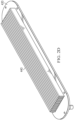
Figure 2D shows a top perspective view of an embodiment of theheat exchanger 40 showing the coolingfins 440. The coolingfins 440 all have all the same lengths and are separated by the same distances. The coolingfins 440 may be arranged orthogonally to thebase body 415. The coolingfins 440 may be tapered towards the end of each fin. -
Figure 2E shows a top perspective view of another embodiment of theheat exchanger 40. Here, aconnector 445 configured to fill first coolant into the direct batterytemperature control system 20 or to de-air thesystem 20 is arranged on themain body 420. Theconnector 445 may be arranged between the coolingfins 440. Theconnector 445 may be arranged at the end of the coolingfins 440 along first direction L. In various embodiments only onesuch connector 445 may be provided on theheat exchanger 40 for the direct batterytemperature control system 20. Theheat exchanger 40 may be arranged at an outside surface of a vehicle such thecooling fins 440 are exposed to ambient air and thebase plate 410 or the secondmain side 424 is enclosed by or located in(side) the vehicle surface. -
Figure 3 shows a perspective view of one battery unit 1 with oneheat exchanger 40 integrated into aboom 2. The battery unit 1 and battery (pack) 60 may be tightly integrated into theboom 2. As can be seen, theheat exchanger 40 and in particular the air to coolant type heat exchanger is integrated in atop surface 22 of theboom 2. Coolingfins 440 extend from themain body 420 to an outside of theboom 2. Themain body 420 is part of thetop surface 22 of theboom 2. Alternatively, themain body 420 is placed on a platform or mesa at thetop surface 22 of theboom 2. The length (first direction L), the width (second direction W) and the height (third direction H, perpendicular to first and second directions L, W) of thefins 440 may be optimized for thermal and aerodynamic performance. For example, the length of thefins 440 may be chosen such that they are 15% to 35% of the length the battery (pack) 60. Alternatively, they are 12% to 32% of the length of the battery (pack) 60 or 20% to 30% of the length of the battery (pack) 60. The height of thefins 440 may be chosen such that they measure 4% to 10% of their length or, alternatively, that they measure 6% to 8% of their length. Moreover, they may measure less than 10% or 8% of their length but more than 0%. - As can be further seen from
Figure 3 , theboom 2 does not have any ducts or openings for an air-to-liquid type heat exchanger. This may lead to the inventiveintegrated heat exchanger 40 having the advantage that theboom 2 can be designed with a smaller cross sections along the direction H and W. The narrower boom may reduce cooling track. Moreover, the inventiveintegrated heat exchanger 40 is advantageous because fewer components are needed since (an) additional and separate liquid-to-liquid type heat exchanger(s) (e.g., plate heat exchanger) is/are not necessary and fewer hydraulic connections (between the components) are used to assemble the battery unit 1. This in turn has the advantage that the inventive battery unit 1 is lighter (less mass) than a comparable conventional battery unit not forgoing the liquid-to-liquid type heat exchanger. This has the further advantage that the pressure drop for the first coolant is smaller than in conventional systems, which means the first coolant has a higher flow rate (assuming the same system pressure drop is achieved) than comparable conventional systems. A lower hydraulic resistance in turn has the advantage that a smaller (and lighter) and/or less powerful electric pump (saving energy) can be used in order to drive or move the first coolant in the coolant lines. - The present disclosure is mainly described with respect to a single vehicle battery unit 1. However, in various embodiments, there may be two, four, six or eight battery units integrated in a boom. Each battery unit may be connected to a vehicle motor and/or motor controller respectively so that, for example, eight battery units and eight vehicle motors and/or motor controllers are integrated in a single boom. In various embodiments, the aeronautic vehicle may have two or four such booms.
- A single boom may have a single port at its outer surface for charging the battery unit 1/
battery 60 or the battery units 1 orbatteries 60. This single port may also includeoutside connectors 80 for proving hot or cold coolant from theground support equipment 100. Theground support equipment 100 is configured to provide warm (hot) or cold coolant and also provide power for charging the battery unit(s) 1/battery orbatteries 60. For example, theground support equipment 100 may charge the battery unit(s) 1/ battery orbatteries 60 while at the same time cooling or heating the battery unit(s) 1/battery orbatteries 60. The single port may be arranged at a side surface of theboom 2 of the vehicle. -
Figure 4 shows asingle boom 2 with 4 VTUs and 4 related battery units 1 (one battery unit for one VTU) according to an embodiment. Each battery unit 1 may be mounted together with a cooling system for a vehicle engine unit (e.g., VTU) described in patent application no. _(attorney docket number TAV-230076075) titled "Cooling System for a Vehicle Engine Unit and Method for Filling such a Cooling System" in theboom 2. This application is incorporated herein by reference in its entirety. An aviation vehicle may have two such booms, each on one side of the aviation vehicle. -
Figure 5 shows a method for operating a battery temperature control system. Themethod 500 comprises sensing 510, by at least one sensor at a battery, a temperature of the battery. Based on the sensed information, at least one controller or a battery management system of the battery may operate 520 the battery temperature control system as follows: 1) Operate the battery temperature control system in a first (operation)mode 522 when the sensed temperature is a above a first predetermined temperature and when the vehicle moves, e.g., is airborne or in-flight. In the first mode the battery is cooled via air-to-coolant cooling (e.g., air to liquid cooling). 2) Operate the battery temperature control system in a second (operation)mode 524 when the sensed temperature is above a second predetermined temperature and when the vehicle is connected to a ground support equipment. In the second mode the battery is cooled via coolant-coolant cooling. This may take place on a hot day, when local environmental conditions around the vehicle are hot, or right after the aviation vehicle landed. The first predetermined temperature and the second predetermined temperature may be the same. 3) Operate the battery temperature control system in a third (operation)mode 526 when the sensed temperature is below a third predetermined temperature and when the vehicle is connected to a ground support vehicle. In the third mode, the battery is heated to precondition it for efficient electrically charging via, e.g., ground support equipment. 4) Operate the battery temperature control system in afourth mode 528 when the sensed temperature is below the first predetermined temperature or the second predetermined temperature and above the third predetermined temperature and optionally when the vehicle is connected to a ground support equipment. Optionally, the battery temperature control system can be operated in a further (operation) mode in order to keep the temperature of the battery above a certain minimum temperature in order to avoid deterioration of the battery. The controller may stop operating in one of the modes and switch to another mode whenever the sensed temperature in the battery passes one of the predetermined temperatures. - While this invention has been described with reference to illustrative embodiments, this description is not intended to be construed in a limiting sense. Various modifications and combinations of the illustrative embodiments, as well as other embodiments of the invention, will be apparent to persons skilled in the art upon reference to the description. It is therefore intended that the appended claims encompass any such modifications or embodiments.
Claims (14)
- A heat exchanger comprising:a base body;cooling fins protruding from a first side of the base body;first channels integrated in the base body and connected to a first connector and a second connector, the first channels configured to guide a first coolant; andsecond channels integrated in the base body and connected to a first connector and a second connector, the second channels configured to guide a second coolant,wherein the first channels are separate from the second channels, andwherein the heat exchanger is capable of being integrated in an outside surface of a vehicle.
- The heat exchanger of claim 1, wherein the first and second connectors of the first channels and the second channels are arranged on a second side of the base body facing away from the cooling fins.
- The heat exchanger of claim 1 or claim 2, wherein the first and second connectors of the first channels are arranged on opposite ends of the base body, and wherein the first and second connectors of the second channels are arranged on the opposite ends of the base body; and
optionally or preferably wherein a distance spacing apart the first and second connectors of the second channels is smaller than a distance spacing apart the first and second connectors of the first channels. - The heat exchanger of claim 1 or claim 2 or claim 3, wherein the cooling fins are orthogonally arranged on the base body.
- The heat exchanger of any preceding claim, wherein the base body includes a heat exchange and separating structure, wherein the first channels are arranged between the cooling fins and the heat exchange and separating structure, and wherein the second channels are arranged on a side of the heat exchange and separating structure facing away from the cooling fins; andoptionally or preferably wherein the heat exchange and separating structure is a thin metal plate comprising aluminum; andfurther optionally or preferably wherein the heat exchange and separating structure further comprises turbulators.
- The heat exchanger of any preceding claim, further comprising a third connector connected to the first channels, wherein the third connector is configured to fill or de-air the first channels.
- A vehicle comprising:a heat exchanger comprising:first channels integrated into the heat exchanger and connected to a first connector and a second connector; andsecond cooling and heating channels integrated into the heat exchanger and connected to a first connector and a second connector,wherein the first channels are separate from the second channels;a battery pack; andan electric pump,first coolant lines connecting the battery pack and the pump to the first and second connectors of the first channels of the heat exchanger thereby forming a closed loop; andsecond coolant lines connecting the first and second connectors of the second channels to outside connectors,wherein the outside connectors are arranged at an outside surface of the vehicle.
- The vehicle of claim 7, wherein the heat exchanger is arranged at the outside surface of the vehicle; andoptionally or preferably wherein the outside surface of the vehicle is a portion of boom of an aircraft; andfurther optionally or preferably wherein the heat exchanger is integrated in an upper surface of the boom facing the same side as a rotor or a propeller arranged at the boom, and wherein the outside connectors are integrated in a side surface of the boom; andfurther optionally or preferably wherein the heat exchanger comprises cooling fins extending orthogonally from the outside surface of the vehicle.
- The vehicle of claim 7 or claim 8, wherein the first and second channels are integrated in the base body, and wherein the base body includes a heat exchange and separating structure arranged between the first channels and the second channels.
- The vehicle of claim 7 or claim 8 or claim 9, wherein the outside connectors are connectable to a ground support equipment and are configured to receive warm or cold coolant.
- A method for operating a battery temperature control system in the vehicle according to claim 10, the method comprising:cooling the battery pack via a first coolant flowing in the first coolant lines when a temperature of the battery pack is above a first predetermined temperature or a second predetermined temperature; andheating the battery pack via the first coolant flowing in the first coolant lines when the temperature of the battery pack is below a third predetermined temperature.
- The method of claim 11,wherein the first coolant in first coolant lines is cooled via air moving over cooling fins of the heat exchanger, orwherein the first coolant in the first coolant lines is cooled via the heat exchanger and second coolant lines.
- The method of claim 11 or claim 12, wherein the first coolant in the first coolant lines is heated via the heat exchanger and a second coolant flowing in the second coolant lines.
- A vehicle comprising:a battery temperature control system comprising a battery pack; anda battery management system in connection with the battery temperature control system and configured to:operate the battery temperature control system in a first cooling mode when a temperature of the battery is above a first predetermined temperature, the first mode configured to cool a coolant;operate the battery temperature control system in a second cooling mode when the temperature of the battery is above a second predetermined temperature, the second mode configured to cool the coolant;operate the battery temperature control system in a third heating mode when the temperature of the battery is below a third predetermined temperature, the third mode configured to heat the coolant; andoperate the battery temperature control system in a fourth idle mode when the temperature of the battery is between the first predetermined temperature or the second predetermined temperature and the third predetermined temperature.
Applications Claiming Priority (1)
| Application Number | Priority Date | Filing Date | Title |
|---|---|---|---|
| US18/498,929 US20250140977A1 (en) | 2023-10-31 | 2023-10-31 | Battery cooling system and method for operating a battery cooling system |
Publications (1)
| Publication Number | Publication Date |
|---|---|
| EP4549865A1 true EP4549865A1 (en) | 2025-05-07 |
Family
ID=89223322
Family Applications (1)
| Application Number | Title | Priority Date | Filing Date |
|---|---|---|---|
| EP23217379.9A Pending EP4549865A1 (en) | 2023-10-31 | 2023-12-15 | Battery cooling system and method for operating a battery cooling system |
Country Status (2)
| Country | Link |
|---|---|
| US (1) | US20250140977A1 (en) |
| EP (1) | EP4549865A1 (en) |
Citations (6)
| Publication number | Priority date | Publication date | Assignee | Title |
|---|---|---|---|---|
| JP2002098424A (en) * | 2000-09-25 | 2002-04-05 | Zexel Valeo Climate Control Corp | Refrigerating cycle |
| US6540015B1 (en) * | 1999-09-16 | 2003-04-01 | Denso Corporation | Heat exchanger and method for manufacturing the same |
| US20130032315A1 (en) * | 2010-04-14 | 2013-02-07 | Kaeser Kompressoren Ag | Refrigerant dryer such as a compressed air refrigerant dryer, and heat exchanger for a refrigerant dryer such as a compressed air refrigerant dryer |
| CN103502763A (en) * | 2011-05-06 | 2014-01-08 | 三菱电机株式会社 | Heat exchanger and refrigeration cycle device provided with same |
| CA3208204A1 (en) * | 2020-08-26 | 2022-08-11 | Zhaohui Li | Heat exchanger, electric control box and air conditioning system |
| FR3129717A1 (en) * | 2021-11-29 | 2023-06-02 | Valeo Systemes Thermiques | HEAT EXCHANGER FOR ELECTRIC OR HYBRID VEHICLES |
-
2023
- 2023-10-31 US US18/498,929 patent/US20250140977A1/en active Pending
- 2023-12-15 EP EP23217379.9A patent/EP4549865A1/en active Pending
Patent Citations (6)
| Publication number | Priority date | Publication date | Assignee | Title |
|---|---|---|---|---|
| US6540015B1 (en) * | 1999-09-16 | 2003-04-01 | Denso Corporation | Heat exchanger and method for manufacturing the same |
| JP2002098424A (en) * | 2000-09-25 | 2002-04-05 | Zexel Valeo Climate Control Corp | Refrigerating cycle |
| US20130032315A1 (en) * | 2010-04-14 | 2013-02-07 | Kaeser Kompressoren Ag | Refrigerant dryer such as a compressed air refrigerant dryer, and heat exchanger for a refrigerant dryer such as a compressed air refrigerant dryer |
| CN103502763A (en) * | 2011-05-06 | 2014-01-08 | 三菱电机株式会社 | Heat exchanger and refrigeration cycle device provided with same |
| CA3208204A1 (en) * | 2020-08-26 | 2022-08-11 | Zhaohui Li | Heat exchanger, electric control box and air conditioning system |
| FR3129717A1 (en) * | 2021-11-29 | 2023-06-02 | Valeo Systemes Thermiques | HEAT EXCHANGER FOR ELECTRIC OR HYBRID VEHICLES |
Also Published As
| Publication number | Publication date |
|---|---|
| US20250140977A1 (en) | 2025-05-01 |
Similar Documents
| Publication | Publication Date | Title |
|---|---|---|
| US11180044B2 (en) | Electric vehicle cooling system | |
| US11214114B2 (en) | Electric vehicle thermal management system | |
| US20220072928A1 (en) | Vehicle Thermal Management System and Heat Exchangers | |
| US11660970B2 (en) | On-board liquid-cooled or gas-cooled charging cable for electric vehicles | |
| US20220285753A1 (en) | Aircraft battery pack and associated cooling system | |
| JP2022530619A (en) | Battery heat management system and method | |
| EP1261065A2 (en) | Thermal management blanketing and jacketing for battery system modules | |
| US20130183555A1 (en) | Cooling system for vehicle batteries | |
| US11646461B2 (en) | Battery cooling systems and methods | |
| US11768036B2 (en) | Heat exchanger and system for cooling a fluid comprising such a heat exchanger | |
| KR20000064376A (en) | Heat exchanger device for air conditioning system | |
| CN106225529A (en) | A kind of plate type heat exchanger | |
| AU2020227257B2 (en) | Thermal management system | |
| EP3560799B1 (en) | Hood | |
| US20230100546A1 (en) | Cooling system for an electric vehicle | |
| CN115441093A (en) | A battery module and aircraft containing the battery module | |
| EP4549865A1 (en) | Battery cooling system and method for operating a battery cooling system | |
| CN211182455U (en) | Battery liquid cooling device | |
| CN212412130U (en) | Power battery thermal management system with temperature adjustment function under cold and hot conditions | |
| CN115367118A (en) | Thermal management system of tilt rotor aircraft | |
| US20250279495A1 (en) | Versatile rechargeable energy storage system tray cooling | |
| CN219584472U (en) | Aircraft wing oil tank cooling system | |
| EP3702285A1 (en) | Thermal management system | |
| CN212783577U (en) | A power battery water-cooled cooling system for electric vehicles | |
| GB2581795A (en) | Thermal management system |
Legal Events
| Date | Code | Title | Description |
|---|---|---|---|
| PUAI | Public reference made under article 153(3) epc to a published international application that has entered the european phase |
Free format text: ORIGINAL CODE: 0009012 |
|
| STAA | Information on the status of an ep patent application or granted ep patent |
Free format text: STATUS: REQUEST FOR EXAMINATION WAS MADE |
|
| 17P | Request for examination filed |
Effective date: 20231218 |
|
| AK | Designated contracting states |
Kind code of ref document: A1 Designated state(s): AL AT BE BG CH CY CZ DE DK EE ES FI FR GB GR HR HU IE IS IT LI LT LU LV MC ME MK MT NL NO PL PT RO RS SE SI SK SM TR |