EP4549838A1 - Cryogenic refrigerator - Google Patents
Cryogenic refrigerator Download PDFInfo
- Publication number
- EP4549838A1 EP4549838A1 EP23830874.6A EP23830874A EP4549838A1 EP 4549838 A1 EP4549838 A1 EP 4549838A1 EP 23830874 A EP23830874 A EP 23830874A EP 4549838 A1 EP4549838 A1 EP 4549838A1
- Authority
- EP
- European Patent Office
- Prior art keywords
- cold head
- vacuum container
- flexible line
- cryogenic refrigerator
- working gas
- Prior art date
- Legal status (The legal status is an assumption and is not a legal conclusion. Google has not performed a legal analysis and makes no representation as to the accuracy of the status listed.)
- Pending
Links
Images


Classifications
-
- F—MECHANICAL ENGINEERING; LIGHTING; HEATING; WEAPONS; BLASTING
- F25—REFRIGERATION OR COOLING; COMBINED HEATING AND REFRIGERATION SYSTEMS; HEAT PUMP SYSTEMS; MANUFACTURE OR STORAGE OF ICE; LIQUEFACTION SOLIDIFICATION OF GASES
- F25B—REFRIGERATION MACHINES, PLANTS OR SYSTEMS; COMBINED HEATING AND REFRIGERATION SYSTEMS; HEAT PUMP SYSTEMS
- F25B9/00—Compression machines, plants or systems, in which the refrigerant is air or other gas of low boiling point
- F25B9/14—Compression machines, plants or systems, in which the refrigerant is air or other gas of low boiling point characterised by the cycle used, e.g. Stirling cycle
-
- F—MECHANICAL ENGINEERING; LIGHTING; HEATING; WEAPONS; BLASTING
- F25—REFRIGERATION OR COOLING; COMBINED HEATING AND REFRIGERATION SYSTEMS; HEAT PUMP SYSTEMS; MANUFACTURE OR STORAGE OF ICE; LIQUEFACTION SOLIDIFICATION OF GASES
- F25B—REFRIGERATION MACHINES, PLANTS OR SYSTEMS; COMBINED HEATING AND REFRIGERATION SYSTEMS; HEAT PUMP SYSTEMS
- F25B9/00—Compression machines, plants or systems, in which the refrigerant is air or other gas of low boiling point
-
- F—MECHANICAL ENGINEERING; LIGHTING; HEATING; WEAPONS; BLASTING
- F25—REFRIGERATION OR COOLING; COMBINED HEATING AND REFRIGERATION SYSTEMS; HEAT PUMP SYSTEMS; MANUFACTURE OR STORAGE OF ICE; LIQUEFACTION SOLIDIFICATION OF GASES
- F25B—REFRIGERATION MACHINES, PLANTS OR SYSTEMS; COMBINED HEATING AND REFRIGERATION SYSTEMS; HEAT PUMP SYSTEMS
- F25B9/00—Compression machines, plants or systems, in which the refrigerant is air or other gas of low boiling point
- F25B9/002—Compression machines, plants or systems, in which the refrigerant is air or other gas of low boiling point characterised by the refrigerant
-
- F—MECHANICAL ENGINEERING; LIGHTING; HEATING; WEAPONS; BLASTING
- F25—REFRIGERATION OR COOLING; COMBINED HEATING AND REFRIGERATION SYSTEMS; HEAT PUMP SYSTEMS; MANUFACTURE OR STORAGE OF ICE; LIQUEFACTION SOLIDIFICATION OF GASES
- F25D—REFRIGERATORS; COLD ROOMS; ICE-BOXES; COOLING OR FREEZING APPARATUS NOT OTHERWISE PROVIDED FOR
- F25D19/00—Arrangement or mounting of refrigeration units with respect to devices or objects to be refrigerated, e.g. infrared detectors
Definitions
- the present invention relates to a cryogenic refrigerator.
- Cryogenic refrigerators represented by Gifford-McMahon (GM) cryocooler are often used to provide cryogenic cooling to various cooling targets, for example, to cool superconductivity equipment or to condense cryogenic liquid such as liquid helium.
- GM Gifford-McMahon
- a thermal switch that thermally connects a cryogenic refrigerator to a cooling target in a cryostat or disconnects the cryogenic refrigerator from the cooling target in the cryostat by installing the cryogenic refrigerator in the cryostat via a bellows and by using upward or downward movement of the cryogenic refrigerator accompanying expansion or contraction of the bellows.
- the cryogenic refrigerator When the thermal switch of the above-described type is turned on (that is, when the cryogenic refrigerator is thermally connected to the cooling target), the cryogenic refrigerator can be rigidly fixed to the cryostat. Contrary to this, when the thermal switch is turned off (that is, when the cryogenic refrigerator is temporarily disconnected from the cooling target), the cryogenic refrigerator is likely to be supported by the cryostat having low rigidity, for example, because of flexibility of the bellows.
- cryogenic refrigerator When the cryogenic refrigerator is operated at a site, various pipes and wires such as a flexible hose for supplying and collecting a working gas and a cable for supplying power are connected to the cryogenic refrigerator and extend around the cryogenic refrigerator.
- a cryogenic refrigerator One of the risks assumed in a general setup of such a cryogenic refrigerator is that there is a possibility that an unexpected large external force may act on the cryogenic refrigerator from the pipes, for example, as in a case where a worker passing near the cryogenic refrigerator hooks his or her foot on the pipes and stumbles.
- Such an unexpected external force may cause a problem, particularly when the thermal switch is off.
- a position and posture of the cryogenic refrigerator may be disturbed by the external force, and the cryogenic refrigerator may interfere with or collide with a surrounding structure. In the worst case, the cryogenic refrigerator or a support structure of the cryogenic refrigerator may be damaged.
- One of exemplary objects of a certain aspect of the present invention is to protect a cryogenic refrigerator from an unexpected external force.
- a cryogenic refrigerator includes a cold head that is mountable on a vacuum container, a cold head mount configured to couple the cold head with the vacuum container to allow movement of the cold head with respect to the vacuum container, a flexible line that is connected to the cold head outside the vacuum container, and a flexible line holder configured to hold the flexible line in a fixed manner with respect to the vacuum container.
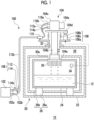
- Fig. 1 is a view schematically showing a cryogenic device 10 according to an embodiment.
- the cryogenic device 10 can be used as a storage device for cryogenic liquid.
- the cryogenic device 10 includes a vacuum container 20 for storing cryogenic liquid 12 such as liquid hydrogen or another liquid and a cryogenic refrigerator 100 for cooling the cryogenic liquid 12, which is stored, to a cryogenic temperature equal to or lower than a liquefaction temperature of the cryogenic liquid 12 (approximately -253°C (20 K) in a case of liquid hydrogen).
- the vacuum container 20 includes an outer tank 22 and an inner tank 24.
- a vacuum heat insulation layer 26 is formed between the outer tank 22 and the inner tank 24.
- the outer tank 22 is configured to separate the vacuum heat insulation layer 26 from an ambient environment (for example, a room temperature atmospheric pressure environment) of the cryogenic device 10.
- the inner tank 24 is configured to separate an internal volume of the inner tank 24 from the vacuum heat insulation layer 26.
- the cryogenic liquid 12 is accommodated in the inner tank 24.
- the outer tank 22 and the inner tank 24 are formed of a metal material such as stainless steel or another suitable high-strength material to withstand a pressure difference between an inside and an outside.
- a heat insulation structure 28 including a heat insulation support 28a and a heat insulation layer 28b may be disposed in the vacuum heat insulation layer 26.
- the heat insulation support 28a is formed of, for example, a hard material having heat insulation properties such as fiber-reinforced plastic, and is configured to support the inner tank 24 in the outer tank 22.
- the heat insulation layer 28b may include a multilayer insulation (MLI).
- MMI multilayer insulation
- the heat insulation structure 28 may include a granular or other-shaped heat insulation material (for example, granular perlite) filled in the vacuum heat insulation layer 26.
- the inner tank 24 includes a recondensing unit 30 provided on a tank wall of the inner tank 24.
- the recondensing unit 30 is cooled from the outside of the inner tank 24 by the cryogenic refrigerator 100.
- the recondensing unit 30 includes a heat transfer surface 30a that is exposed to the outside of the inner tank 24 and comes into contact with the cryogenic refrigerator 100.
- the recondensing unit 30 may have a fin-shaped protrusion or a recess and protrusion inside the inner tank 24 in order to increase a surface area in contact with the cryogenic liquid 12 or the vaporized cryogenic liquid 12.
- the recondensing unit 30 is formed of, for example, pure copper (for example, oxygen-free copper, tough pitch copper, or the like), or other high thermal conductivity metal.
- the cryogenic refrigerator 100 includes a compressor 102, a cold head 104 that is mountable on the vacuum container 20, and a cold head mount 106 configured to couple the cold head 104 with the vacuum container 20 to allow movement of the cold head 104 with respect to the vacuum container 20.
- the compressor 102 is configured to recover a working gas of the cryogenic refrigerator 100 from the cold head 104, increase a pressure of the recovered working gas, and supply the working gas to the cold head 104 again.
- the cold head 104 is also referred to as an expander or a cryocooler.
- the compressor 102 and the cold head 104 configure a refrigeration cycle of the cryogenic refrigerator 100, and thereby the cryogenic refrigerator 100 provides cryogenic cooling.
- the working gas is also referred to as a refrigerant gas and is typically a helium gas, but other suitable gases may be used.
- the cryogenic refrigerator 100 is a single-stage GM cryocooler in the embodiment. Therefore, the cold head 104 includes a cooling stage 104a, a cylinder 104b, a drive unit 104c, and a cold head flange 104d.
- the cooling stage 104a is formed of, for example, pure copper (for example, oxygen-free copper, tough pitch copper, or the like), or other high thermal conductivity metal.
- the cooling stage 104a is cooled to a desired cryogenic temperature, for example, to a temperature range equal to or lower than the liquefaction temperature of the cryogenic liquid 12.
- the cooling stage 104a is cooled to a cooling temperature included in, for example, a temperature range of 10 K to 30 K (for example, a cooling temperature near 20 K, such as 20 K ⁇ 1 K, 20 K ⁇ 2 K, or 20 K ⁇ 5 K).
- the cylinder 104b connects the cooling stage 104a to the cold head flange 104d.
- a displacer (not shown) for controlling a volume of an expansion space of the working gas adjacent to the cooling stage 104a is disposed in the cylinder 104b to be movable in an axial direction (an up-down direction in Fig. 1 ) of the cylinder 104b.
- the cylinder 104b and the cold head flange 104d are typically formed of an appropriate metal material such as stainless steel.
- the drive unit 104c is attached to the cold head flange 104d on a side opposite to the cylinder 104b.
- the drive unit 104c is provided with a cold head drive motor 104e such as an electric motor for driving the displacer in the cylinder 104b, and a pressure control mechanism (not shown) such as a rotary valve for controlling a working gas pressure of the expansion space in the cylinder 104b.
- a cold head drive motor 104e such as an electric motor for driving the displacer in the cylinder 104b
- a pressure control mechanism such as a rotary valve for controlling a working gas pressure of the expansion space in the cylinder 104b.
- a mounting port 32 for mounting the cold head 104 to the vacuum container 20 is provided in the outer tank 22 of the vacuum container 20.
- the cold head 104 is inserted into the vacuum container 20 from the mounting port 32, and is detachably attached to the mounting port 32 via the cold head mount 106.
- the cold head 104 is mounted on the vacuum container 20 such that the cooling stage 104a is disposed in the vacuum heat insulation layer 26 in the vacuum container 20 and the drive unit 104c is disposed outside the vacuum container 20.
- the mounting port 32 is formed in a top plate or an upper portion of the vacuum container 20.
- the cold head 104 is installed in the vacuum container 20 such that a center axis of the cold head 104 coincides with a vertical direction.
- a position of the mounting port 32 and an attachment posture of the cold head 104 are not limited thereto.
- the mounting port 32 may be formed in a bottom plate or a lower portion of the vacuum container 20.
- the cold head 104 can be installed in a desired posture, and may be installed in the vacuum container 20 such that the center axis coincides with an oblique direction or a horizontal direction.
- the cold head mount 106 includes an attachment flange 106a attachable to the vacuum container 20, and an expandable and contractible airtight partition wall 106b that connects the cold head 104 to the attachment flange 106a.
- the attachment flange 106a is fixed to the mounting port 32 of the vacuum container 20 by using, for example, a fastening member such as a bolt, or other appropriate fixing means.
- the attachment flange 106a may be fixed to the vacuum container 20 via a connection member instead of being directly fixed to the vacuum container 20 as shown.
- the expandable and contractible airtight partition wall 106b is, for example, a bellows, and connects the cold head flange 104d to the attachment flange 106a. Therefore, the mounting port 32 is closed by the attachment flange 106a, the airtight partition wall 106b, and the cold head flange 104d, and airtightness of the vacuum container 20 is maintained.
- the attachment flange 106a has an opening at a center portion, and the expandable and contractible airtight partition wall 106b is formed in a tubular shape.
- the cylinder 104b of the cold head 104 extends into the vacuum container 20 from the cold head flange 104d through an inside of the expandable and contractible airtight partition wall 106b and the opening of the attachment flange 106a.
- the cold head mount 106 includes a drive source 106c mounted on the cold head mount 106 and configured to move the cold head 104 with respect to the vacuum container 20.
- the drive source 106c may be configured to move the cold head 104 by using appropriate motive power such as a pneumatic pressure, a hydraulic pressure, an electric motor, or an electromagnet, or may be operable to move the cold head 104 manually.
- the drive source 106c is installed on the attachment flange 106a, and is connected to the cold head flange 104d to move the cold head flange 104d in an expansion and contraction direction of the airtight partition wall 106b. Therefore, by operating the drive source 106c, the cold head flange 104d can be moved with respect to the attachment flange 106a while the airtight partition wall 106b is expanded and contracted. In an example shown in Fig. 1 , the drive source 106c can raise and lower the cold head flange 104d with respect to the attachment flange 106a (that is, the cold head 104 with respect to the vacuum container 20) upward and downward.
- the cold head mount 106 can operate as a thermal switch that thermally connects the cold head 104 to the inner tank 24 of the vacuum container 20 or disconnects the cold head 104 from the inner tank 24 of the vacuum container 20, which is a storage tank for the cryogenic liquid 12.
- Fig. 1 shows an on-state of the thermal switch with a solid line, and shows an off-state of the thermal switch with a broken line.
- the thermal switch is turned on, the cooling stage 104a of the cold head 104 comes into contact with the heat transfer surface 30a of the recondensing unit 30 of the inner tank 24.
- the cooling stage 104a can cool the recondensing unit 30 to the liquefaction temperature of the cryogenic liquid 12, can hold the cryogenic liquid 12 in the inner tank 24, and can recondense the vaporized cryogenic liquid 12.
- the cooling stage 104a is separated from the heat transfer surface 30a of the recondensing unit 30. Since the cooling stage 104a is disposed in the vacuum heat insulation layer 26, thermal contact between the cooling stage 104a and the recondensing unit 30 is released. In this case, the cold head 104 does not cool the inner tank 24.
- Such a thermal switch is advantageous for improving an energy saving property of the cryogenic device 10.
- the cold head 104 becomes a heat transfer path from the ambient environment of the cryogenic device 10 to the inner tank 24, and undesirable heat intrusion to the cryogenic liquid 12 may occur.
- the cryogenic refrigerator 100 is stopped, the cold head 104 is separated from the inner tank 24 by using the thermal switch. In this manner, intrusion heat can be blocked.
- the cryogenic device 10 may be provided with a sensor 34 that measures a physical quantity of the cryogenic liquid 12.
- the drive source 106c may be configured to receive an output signal from the sensor 34 indicating the measured physical quantity of the cryogenic liquid 12 and to move the cold head 104 based on the measured physical quantity of the cryogenic liquid 12.
- the senor 34 may be disposed in the inner tank 24 of the vacuum container 20 and may be configured to measure an internal pressure of the inner tank 24.
- a vapor pressure of the cryogenic liquid 12 in the inner tank 24 is measured by the sensor 34.
- the drive source 106c may compare the measured pressure with a pressure threshold value, turn on the thermal switch in a case where the measured pressure exceeds the pressure threshold value, and turn off the thermal switch in a case where the measured pressure falls below the pressure threshold value. In this way, the internal pressure of the inner tank 24 can be maintained at an appropriate pressure corresponding to the pressure threshold value.
- the sensor 34 may be configured to measure a temperature of the cryogenic liquid 12.
- the sensor 34 may be disposed in the inner tank 24 or may be installed in the recondensing unit 30 of the inner tank 24.
- the drive source 106c may compare the measured temperature with a temperature threshold value, turn on the thermal switch in a case where the measured temperature exceeds the temperature threshold value, and turn off the thermal switch in a case where the measured temperature falls below the temperature threshold value. In this way, the cryogenic liquid 12 can be maintained at an appropriate temperature corresponding to the temperature threshold value.
- the cryogenic refrigerator 100 includes a flexible line 108 that is connected to the cold head 104 outside the vacuum container 20, and a flexible line holder 110 configured to hold the flexible line 108 in a fixed manner with respect to the vacuum container 20.
- the flexible line 108 connects the drive unit 104c of the cold head 104 to an external element (for example, the compressor 102) disposed outside the vacuum container 20.
- the flexible line holder 110 is fixed to the attachment flange 106a of the cold head mount 106, and holds the flexible line 108 in the middle of a path from the cold head 104 to an external element.
- the flexible line holder 110 corresponds to a connection point at which the flexible line 108 is fixed to the vacuum container 20.
- the compressor 102 may be disposed in a position remote from the cold head 104 and the vacuum container 20, for example, the compressor 102 may be installed in a room or section in which the cold head 104 and the vacuum container 20 is installed or in another room or section.
- the length of the flexible line 108 may be 10 m or more.
- the flexible line holder 110 is fixed to the attachment flange 106a. Accordingly, the flexible line holder 110 holds the flexible line 108 at an end portion (for example, an end portion of the flexible line 108 having a length of 10% or less or 5% or less of the total length of the flexible line 108) of the flexible line 108 on a cold head 104 side.
- the flexible line 108 includes a working gas line for supplying the working gas to the cold head 104 or collecting the working gas from the cold head 104, more specifically, a gas supply line 112 and a gas recovery line 114.
- the gas supply line 112 connects a working gas discharge port 102a of the compressor 102 to a high-pressure port 116a of the cold head 104
- the gas recovery line 114 connects a working gas suction port 102b of the compressor 102 to a low-pressure port 116b of the cold head 104.
- the working gas of the cryogenic refrigerator 100 is supplied from the compressor 102 to the cold head 104 through the gas supply line 112, and is recovered from the cold head 104 to the compressor 102 through the gas recovery line 114.
- a pressure of the working gas in the gas supply line 112 and a pressure of the working gas in the gas recovery line 114 are both considerably higher than an atmospheric pressure, and can be referred to as a first high pressure and a second high pressure, respectively.
- the first high pressure and the second high pressure are also simply referred to as a high pressure and a low pressure, respectively.
- the high pressure is, for example, 2 to 3 MPa.
- the low pressure is, for example, 0.5 to 1.5 MPa and is, for example, about 0.8 MPa.
- the flexible line holder 110 may include a working gas line holder that holds the working gas line.
- the flexible line holder 110 may include a first holder that holds the gas supply line 112 and a second holder that holds the gas recovery line 114, and the two holders may be fixed to the attachment flange 106a.
- the flexible line holder 110 can be rigidly fixed to the attachment flange 106a by using, for example, screwing, welding, or other appropriate fixing means.
- the two holders may be disposed side by side on the attachment flange 106a, may be disposed to interpose the drive unit 104c on the attachment flange 106a, or may be disposed at any other optional location on the attachment flange 106a.
- the flexible line holder 110 is attached to an upper surface of the attachment flange 106a, but may be attached to a lower surface of the attachment flange 106a or another part.
- the gas supply line 112 includes a first part 112a extending from the high-pressure port 116a of the cold head 104 and a second part 112b extending from the working gas discharge port 102a of the compressor 102.
- the flexible line holder 110 may be configured as an intermediate coupling including an internal flow path through which the working gas of the cryogenic refrigerator 100 can flow.
- the first holder may be a first intermediate coupling including a first internal flow path.
- the first part 112a of the gas supply line 112 is connected to the first holder at one end and is connected to the high-pressure port 116a at the other end.
- the second part 112b of the gas supply line 112 is connected to the first holder at one end and is connected to the working gas discharge port 102a at the other end. In this way, the high-pressure working gas discharged from the working gas discharge port 102a flows into the cold head 104 through the second part 112b, the first holder, and the first part 112a.
- the gas recovery line 114 includes a first part 114a extending from the low-pressure port 116b of the cold head 104 and a second part 114b extending from the working gas suction port 102b of the compressor 102.
- the flexible line holder 110 may be configured as the intermediate coupling including the internal flow path through which the working gas of the cryogenic refrigerator 100 can flow.
- the second holder may be a second intermediate coupling including a second internal flow path.
- the first part 114a of the gas recovery line 114 is connected to the second holder at one end and is connected to the low-pressure port 116b at the other end.
- the second part 114b of the gas recovery line 114 is connected to the second holder at one end and is connected to the working gas suction port 102b at the other end. In this way, the low-pressure working gas flowing out from the low-pressure port 116b of the cold head 104 is recovered to the compressor 102 through the first part 114a, the second holder, and the second part 114b.
- the gas supply line 112 and the gas recovery line 114 may be, for example, a pipe having flexibility such as a flexible hose.
- the gas supply line 112 and the gas recovery line 114 may be attachable to and detachable from the compressor 102, the cold head 104, and the flexible line 108, for example, to be convenient for replacement due to wear.
- Fig. 2 is a view schematically showing a working gas line of a cryogenic refrigerator according to a comparative example.
- a cryogenic refrigerator 200 includes a compressor 202 and a cold head 204.
- the compressor 202 and the cold head 204 are connected to each other by a flexible hose 206.
- the cold head 204 is mounted on the vacuum container 20 such that the cold head 204 can be moved (raised and lowered) with respect to the vacuum container 20.
- the cold head 204 can operate as a thermal switch that thermally connects the cold head 204 to an object 208 to be cooled or disconnects the cold head 204 from the object 208 to be cooled by raising and lowering the cold head 204.
- a case where the thermal switch is off, that is, a state where the cold head 204 is separated from the object 208 to be cooled is shown.
- a worker passing near the cryogenic refrigerator 200 may hook his or her foot 210 on the flexible hose 206 and stumble.
- the flexible hose 206 may be instantly strongly pulled by the hooked foot 210, and a strong lateral load 212 may act on the cold head 204.
- the thermal switch is off, the cold head 204 is supported to the vacuum container 20 by a support structure having low rigidity such as a bellows. Therefore, the lateral load 212 may disturb a position and posture of the cryogenic refrigerator 200 as shown by a black arrow 214 and a broken line in Fig. 2 , and may cause the cryogenic refrigerator 200 to collide with a surrounding structure such as the vacuum container 20, the object 208 to be cooled, or the like in some cases. As a result, the cryogenic refrigerator 200 or the surrounding structure may be damaged.
- the flexible line 108 is held by the flexible line holder 110 in a fixed manner with respect to the vacuum container 20.
- a second part for example, 112b and 114b
- a tension force acting on the second part is merely received by the attachment flange 106a and the vacuum container 20 to which the flexible line holder 110 is fixed.
- the tension force is not directly transmitted to the cold head 104, and it is expected that a position and posture of the cold head 104 can be held even when the thermal switch is off. In this way, the cryogenic refrigerator 100 can be protected from an unexpected external force.
- Fig. 3 is a view schematically showing exemplary electrical connection applicable to the cryogenic refrigerator 100 shown in Fig. 1 .
- the flexible line 108 may be a power supply cable for supplying power to the cold head 104.
- the power supply cable connects a power supply 118 disposed outside the vacuum container 20 to the drive unit 104c (for example, the cold head drive motor 104e shown in Fig. 1 ) of the cold head 104.
- the compressor 102 may be used as the power supply 118.
- the flexible line holder 110 may be a cable holder that is fixed to the attachment flange 106a and holds the power supply cable.
- the flexible line holder 110 is attached to the attachment flange 106a such that the flexible line holder 110 penetrates the attachment flange 106a. Accordingly, the power supply cable can be guided from one surface of the attachment flange 106a (for example, the upper surface) to a surface on a side opposite thereto (for example, the lower surface).
- a degree of freedom in the disposition of the power supply cable can be increased as compared to a case where the power supply cable is routed only on an upper surface side of the attachment flange 106a.
- cryogenic refrigerator 100 can be protected from an unexpected external force as in the embodiment described with reference to Figs. 1 and 2 . That is, even when an unexpected external force acts on the second part of the flexible line 108 extending from the flexible line holder 110 to the power supply 118, the attachment flange 106a and the vacuum container 20 to which the flexible line holder 110 is fixed can receive the external force. It is possible to reduce an adverse effect on the cold head 104 caused by the external force.
- the flexible line holder 110 of a type that penetrates the attachment flange 106a as described above may be used as the holder for the working gas line described with reference to Fig. 1 .
- Fig. 4 is a view schematically showing an exemplary drive source applicable to the cryogenic refrigerator 100 shown in Fig. 1 .
- the drive source 106c is attached to a plate-shaped support body 120 disposed above the cold head 104.
- the drive source 106c includes a movable piston 122 that penetrates the support body 120 and protrudes downward.
- a plurality of (for example, four) guide rods 124 are erected on the attachment flange 106a to surround the cold head 104, and the support body 120 is fixed to distal ends of the guide rods 124.
- the guide rods 124 penetrate the cold head flange 104d in the up-down direction, and the cold head flange 104d is movable in the up-down direction along the guide rods 124.
- a movable frame 126 including support columns 126a and a movable plate 126b is installed on the cold head flange 104d.
- the support columns 126a are erected on the cold head flange 104d, and the movable plate 126b is fixed to the support columns 126a to bridge distal ends of the support columns 126a.
- a lower end of the movable piston 122 is fixed to the movable plate 126b.
- the cold head flange 104d can also move up and down via the movable frame 126.
- the cold head flange 104d moves up and down along the guide rods 124, accompanying expansion and contraction of the airtight partition wall 106b.
- the drive source 106c can provide the movement of the cold head 104 with respect to the vacuum container 20.
- the cryogenic refrigerator 100 may include an additional flexible line 128 connected to the drive source 106c, and an additional flexible line holder 130 configured to hold the additional flexible line 128 in a fixed manner with respect to the vacuum container 20.
- the drive source 106c may be, for example, an air cylinder.
- the flexible line 128 may be a compressed-air line for supplying compressed air to the drive source 106c and collecting compressed air from the drive source 106c.
- the flexible line holder 130 may be a holder that is fixed to the attachment flange 106a and holds the compressed-air line.
- the cryogenic refrigerator 100 can be protected from an unexpected external force. That is, even when an unexpected external force acts on the second part of the flexible line 128 extending from the flexible line holder 130 to a compressed-air source 132, the attachment flange 106a and the vacuum container 20 to which the flexible line holder 130 is fixed can receive the external force. It is possible to reduce an adverse effect on the cold head 104 caused by the external force.
- the working gas line holder may be an appropriate fixing tool such as a hose clamp that holds the working gas line, and the fixing tool may be fixed to the attachment flange 106a.
- the working gas line does not need to be divided by the holder (the working gas line need not be divided into the first part and the second part, and may be a single flexible hose) .
- the flexible line holder 110 may be directly fixed to the vacuum container 20.
- the flexible line holder 110 may be fixed to a wall surface of the vacuum container 20 to which the attachment flange 106a is attached (that is, on which the mounting port 32 is provided), or to another part of the vacuum container 20.
- cryogenic refrigerator 100 is a single-stage GM cryocooler
- the cryogenic refrigerator 100 may be a two-stage GM cryocooler.
- the cryogenic refrigerator 100 may provide cryogenic cooling of about 4 K or lower, and the cryogenic liquid 12 may be liquid helium.
- the cryogenic refrigerator 100 may be a pulse tube cryocooler, a Stirling cryocooler, or another type of cryogenic refrigerator.
- cryogenic device 10 is a storage device for the cryogenic liquid 12 as an example
- the cryogenic device 10 may be superconductivity equipment, and the cryogenic refrigerator 100 may be used to cool a superconducting coil disposed in the vacuum container 20.
- the present invention can be used in the field of cryogenic refrigerators.
Landscapes
- Engineering & Computer Science (AREA)
- Physics & Mathematics (AREA)
- Mechanical Engineering (AREA)
- Thermal Sciences (AREA)
- General Engineering & Computer Science (AREA)
- Chemical & Material Sciences (AREA)
- Combustion & Propulsion (AREA)
- Containers, Films, And Cooling For Superconductive Devices (AREA)
Abstract
Description
- The present invention relates to a cryogenic refrigerator.
- Cryogenic refrigerators represented by Gifford-McMahon (GM) cryocooler are often used to provide cryogenic cooling to various cooling targets, for example, to cool superconductivity equipment or to condense cryogenic liquid such as liquid helium. In the related art, it is known that a thermal switch that thermally connects a cryogenic refrigerator to a cooling target in a cryostat or disconnects the cryogenic refrigerator from the cooling target in the cryostat by installing the cryogenic refrigerator in the cryostat via a bellows and by using upward or downward movement of the cryogenic refrigerator accompanying expansion or contraction of the bellows.
- [PTL 1]
Japanese Unexamined Patent Publication No. 2016-211803 - When the thermal switch of the above-described type is turned on (that is, when the cryogenic refrigerator is thermally connected to the cooling target), the cryogenic refrigerator can be rigidly fixed to the cryostat. Contrary to this, when the thermal switch is turned off (that is, when the cryogenic refrigerator is temporarily disconnected from the cooling target), the cryogenic refrigerator is likely to be supported by the cryostat having low rigidity, for example, because of flexibility of the bellows.
- When the cryogenic refrigerator is operated at a site, various pipes and wires such as a flexible hose for supplying and collecting a working gas and a cable for supplying power are connected to the cryogenic refrigerator and extend around the cryogenic refrigerator. One of the risks assumed in a general setup of such a cryogenic refrigerator is that there is a possibility that an unexpected large external force may act on the cryogenic refrigerator from the pipes, for example, as in a case where a worker passing near the cryogenic refrigerator hooks his or her foot on the pipes and stumbles. Such an unexpected external force may cause a problem, particularly when the thermal switch is off. A position and posture of the cryogenic refrigerator may be disturbed by the external force, and the cryogenic refrigerator may interfere with or collide with a surrounding structure. In the worst case, the cryogenic refrigerator or a support structure of the cryogenic refrigerator may be damaged.
- One of exemplary objects of a certain aspect of the present invention is to protect a cryogenic refrigerator from an unexpected external force.
- According to a certain aspect of the present invention, a cryogenic refrigerator includes a cold head that is mountable on a vacuum container, a cold head mount configured to couple the cold head with the vacuum container to allow movement of the cold head with respect to the vacuum container, a flexible line that is connected to the cold head outside the vacuum container, and a flexible line holder configured to hold the flexible line in a fixed manner with respect to the vacuum container.
- According to the present invention, it is possible to protect a cryogenic refrigerator from an unexpected external force.
-
-
Fig. 1 is a view schematically showing a cryogenic device according to an embodiment. -
Fig. 2 is a view schematically showing a working gas line of a cryogenic refrigerator according to a comparative example. -
Fig. 3 is a view schematically showing exemplary electrical connection applicable to a cryogenic refrigerator shown inFig. 1 . -
Fig. 4 is a view schematically showing an exemplary drive source applicable to the cryogenic refrigerator shown inFig. 1 . - Embodiments of the present invention will be described in detail below with reference to the drawings. The same or equivalent components, members, and processing in the description and the drawings will be denoted by the same reference numerals and repeated description thereof will be appropriately omitted. A scale and shape of each part to be shown are conveniently set to facilitate the description, and are not limitedly interpreted as long as not particularly mentioned. The embodiments are exemplary and do not limit the scope of the present invention in any way. All features or combinations thereof described in the embodiments are not necessarily essential to the invention.
-
Fig. 1 is a view schematically showing acryogenic device 10 according to an embodiment. In the embodiment, thecryogenic device 10 can be used as a storage device for cryogenic liquid. Here, thecryogenic device 10 includes avacuum container 20 for storingcryogenic liquid 12 such as liquid hydrogen or another liquid and acryogenic refrigerator 100 for cooling thecryogenic liquid 12, which is stored, to a cryogenic temperature equal to or lower than a liquefaction temperature of the cryogenic liquid 12 (approximately -253°C (20 K) in a case of liquid hydrogen). - The
vacuum container 20 includes anouter tank 22 and aninner tank 24. A vacuumheat insulation layer 26 is formed between theouter tank 22 and theinner tank 24. Theouter tank 22 is configured to separate the vacuumheat insulation layer 26 from an ambient environment (for example, a room temperature atmospheric pressure environment) of thecryogenic device 10. In addition, theinner tank 24 is configured to separate an internal volume of theinner tank 24 from the vacuumheat insulation layer 26. Thecryogenic liquid 12 is accommodated in theinner tank 24. Theouter tank 22 and theinner tank 24 are formed of a metal material such as stainless steel or another suitable high-strength material to withstand a pressure difference between an inside and an outside. - A
heat insulation structure 28 including aheat insulation support 28a and aheat insulation layer 28b may be disposed in the vacuumheat insulation layer 26. Theheat insulation support 28a is formed of, for example, a hard material having heat insulation properties such as fiber-reinforced plastic, and is configured to support theinner tank 24 in theouter tank 22. Theheat insulation layer 28b may include a multilayer insulation (MLI). Together with theheat insulation layer 28b or instead of theheat insulation layer 28b, theheat insulation structure 28 may include a granular or other-shaped heat insulation material (for example, granular perlite) filled in the vacuumheat insulation layer 26. - The
inner tank 24 includes a recondensingunit 30 provided on a tank wall of theinner tank 24. The recondensingunit 30 is cooled from the outside of theinner tank 24 by thecryogenic refrigerator 100. Therecondensing unit 30 includes aheat transfer surface 30a that is exposed to the outside of theinner tank 24 and comes into contact with thecryogenic refrigerator 100. The recondensingunit 30 may have a fin-shaped protrusion or a recess and protrusion inside theinner tank 24 in order to increase a surface area in contact with thecryogenic liquid 12 or the vaporizedcryogenic liquid 12. The recondensingunit 30 is formed of, for example, pure copper (for example, oxygen-free copper, tough pitch copper, or the like), or other high thermal conductivity metal. - The
cryogenic refrigerator 100 includes acompressor 102, acold head 104 that is mountable on thevacuum container 20, and a cold head mount 106 configured to couple thecold head 104 with thevacuum container 20 to allow movement of thecold head 104 with respect to thevacuum container 20. - The
compressor 102 is configured to recover a working gas of thecryogenic refrigerator 100 from thecold head 104, increase a pressure of the recovered working gas, and supply the working gas to thecold head 104 again. Thecold head 104 is also referred to as an expander or a cryocooler. Thecompressor 102 and thecold head 104 configure a refrigeration cycle of thecryogenic refrigerator 100, and thereby thecryogenic refrigerator 100 provides cryogenic cooling. The working gas is also referred to as a refrigerant gas and is typically a helium gas, but other suitable gases may be used. - The
cryogenic refrigerator 100 is a single-stage GM cryocooler in the embodiment. Therefore, thecold head 104 includes acooling stage 104a, acylinder 104b, adrive unit 104c, and acold head flange 104d. Thecooling stage 104a is formed of, for example, pure copper (for example, oxygen-free copper, tough pitch copper, or the like), or other high thermal conductivity metal. During driving of thecryogenic refrigerator 100, thecooling stage 104a is cooled to a desired cryogenic temperature, for example, to a temperature range equal to or lower than the liquefaction temperature of thecryogenic liquid 12. In a case where thecryogenic liquid 12 is liquid hydrogen, thecooling stage 104a is cooled to a cooling temperature included in, for example, a temperature range of 10 K to 30 K (for example, a cooling temperature near 20 K, such as 20 K ± 1 K, 20 K ± 2 K, or 20 K ± 5 K). - The
cylinder 104b connects thecooling stage 104a to thecold head flange 104d. A displacer (not shown) for controlling a volume of an expansion space of the working gas adjacent to thecooling stage 104a is disposed in thecylinder 104b to be movable in an axial direction (an up-down direction inFig. 1 ) of thecylinder 104b. Thecylinder 104b and thecold head flange 104d are typically formed of an appropriate metal material such as stainless steel. Thedrive unit 104c is attached to thecold head flange 104d on a side opposite to thecylinder 104b. Thedrive unit 104c is provided with a coldhead drive motor 104e such as an electric motor for driving the displacer in thecylinder 104b, and a pressure control mechanism (not shown) such as a rotary valve for controlling a working gas pressure of the expansion space in thecylinder 104b. - As shown in
Fig. 1 , amounting port 32 for mounting thecold head 104 to thevacuum container 20 is provided in theouter tank 22 of thevacuum container 20. During mounting, thecold head 104 is inserted into thevacuum container 20 from the mountingport 32, and is detachably attached to the mountingport 32 via the cold head mount 106. Thecold head 104 is mounted on thevacuum container 20 such that thecooling stage 104a is disposed in the vacuumheat insulation layer 26 in thevacuum container 20 and thedrive unit 104c is disposed outside thevacuum container 20. - As an example, the mounting
port 32 is formed in a top plate or an upper portion of thevacuum container 20. Thecold head 104 is installed in thevacuum container 20 such that a center axis of thecold head 104 coincides with a vertical direction. However, a position of the mountingport 32 and an attachment posture of thecold head 104 are not limited thereto. For example, the mountingport 32 may be formed in a bottom plate or a lower portion of thevacuum container 20. Thecold head 104 can be installed in a desired posture, and may be installed in thevacuum container 20 such that the center axis coincides with an oblique direction or a horizontal direction. - The cold head mount 106 includes an
attachment flange 106a attachable to thevacuum container 20, and an expandable and contractibleairtight partition wall 106b that connects thecold head 104 to theattachment flange 106a. Theattachment flange 106a is fixed to the mountingport 32 of thevacuum container 20 by using, for example, a fastening member such as a bolt, or other appropriate fixing means. Theattachment flange 106a may be fixed to thevacuum container 20 via a connection member instead of being directly fixed to thevacuum container 20 as shown. The expandable and contractibleairtight partition wall 106b is, for example, a bellows, and connects thecold head flange 104d to theattachment flange 106a. Therefore, the mountingport 32 is closed by theattachment flange 106a, theairtight partition wall 106b, and thecold head flange 104d, and airtightness of thevacuum container 20 is maintained. - The
attachment flange 106a has an opening at a center portion, and the expandable and contractibleairtight partition wall 106b is formed in a tubular shape. Thecylinder 104b of thecold head 104 extends into thevacuum container 20 from thecold head flange 104d through an inside of the expandable and contractibleairtight partition wall 106b and the opening of theattachment flange 106a. - In addition, the cold head mount 106 includes a
drive source 106c mounted on the cold head mount 106 and configured to move thecold head 104 with respect to thevacuum container 20. Thedrive source 106c may be configured to move thecold head 104 by using appropriate motive power such as a pneumatic pressure, a hydraulic pressure, an electric motor, or an electromagnet, or may be operable to move thecold head 104 manually. - The
drive source 106c is installed on theattachment flange 106a, and is connected to thecold head flange 104d to move thecold head flange 104d in an expansion and contraction direction of theairtight partition wall 106b. Therefore, by operating thedrive source 106c, thecold head flange 104d can be moved with respect to theattachment flange 106a while theairtight partition wall 106b is expanded and contracted. In an example shown inFig. 1 , thedrive source 106c can raise and lower thecold head flange 104d with respect to theattachment flange 106a (that is, thecold head 104 with respect to the vacuum container 20) upward and downward. - In this way, the cold head mount 106 can operate as a thermal switch that thermally connects the
cold head 104 to theinner tank 24 of thevacuum container 20 or disconnects thecold head 104 from theinner tank 24 of thevacuum container 20, which is a storage tank for thecryogenic liquid 12.Fig. 1 shows an on-state of the thermal switch with a solid line, and shows an off-state of the thermal switch with a broken line. When the thermal switch is turned on, thecooling stage 104a of thecold head 104 comes into contact with theheat transfer surface 30a of therecondensing unit 30 of theinner tank 24. In this manner, thecooling stage 104a can cool therecondensing unit 30 to the liquefaction temperature of thecryogenic liquid 12, can hold thecryogenic liquid 12 in theinner tank 24, and can recondense the vaporizedcryogenic liquid 12. On the other hand, when thecold head 104 is lifted by the operation of thedrive source 106c, thecooling stage 104a is separated from theheat transfer surface 30a of therecondensing unit 30. Since thecooling stage 104a is disposed in the vacuumheat insulation layer 26, thermal contact between the coolingstage 104a and therecondensing unit 30 is released. In this case, thecold head 104 does not cool theinner tank 24. - Such a thermal switch is advantageous for improving an energy saving property of the
cryogenic device 10. As exemplary running of thecryogenic refrigerator 100, it is conceivable to stop the cooling driving of thecryogenic refrigerator 100 in a state where thevacuum container 20 is sufficiently cooled. In this case, when thecold head 104 is in contact with theinner tank 24 of thevacuum container 20, thecold head 104 becomes a heat transfer path from the ambient environment of thecryogenic device 10 to theinner tank 24, and undesirable heat intrusion to thecryogenic liquid 12 may occur. On the other hand, when thecryogenic refrigerator 100 is stopped, thecold head 104 is separated from theinner tank 24 by using the thermal switch. In this manner, intrusion heat can be blocked. - In order to switch the thermal switch, the
cryogenic device 10 may be provided with asensor 34 that measures a physical quantity of thecryogenic liquid 12. Thedrive source 106c may be configured to receive an output signal from thesensor 34 indicating the measured physical quantity of thecryogenic liquid 12 and to move thecold head 104 based on the measured physical quantity of thecryogenic liquid 12. - For example, the
sensor 34 may be disposed in theinner tank 24 of thevacuum container 20 and may be configured to measure an internal pressure of theinner tank 24. A vapor pressure of thecryogenic liquid 12 in theinner tank 24 is measured by thesensor 34. Thedrive source 106c may compare the measured pressure with a pressure threshold value, turn on the thermal switch in a case where the measured pressure exceeds the pressure threshold value, and turn off the thermal switch in a case where the measured pressure falls below the pressure threshold value. In this way, the internal pressure of theinner tank 24 can be maintained at an appropriate pressure corresponding to the pressure threshold value. - Alternatively, the
sensor 34 may be configured to measure a temperature of thecryogenic liquid 12. In this case, thesensor 34 may be disposed in theinner tank 24 or may be installed in therecondensing unit 30 of theinner tank 24. Thedrive source 106c may compare the measured temperature with a temperature threshold value, turn on the thermal switch in a case where the measured temperature exceeds the temperature threshold value, and turn off the thermal switch in a case where the measured temperature falls below the temperature threshold value. In this way, thecryogenic liquid 12 can be maintained at an appropriate temperature corresponding to the temperature threshold value. - In addition, the
cryogenic refrigerator 100 includes aflexible line 108 that is connected to thecold head 104 outside thevacuum container 20, and aflexible line holder 110 configured to hold theflexible line 108 in a fixed manner with respect to thevacuum container 20. Theflexible line 108 connects thedrive unit 104c of thecold head 104 to an external element (for example, the compressor 102) disposed outside thevacuum container 20. Theflexible line holder 110 is fixed to theattachment flange 106a of the cold head mount 106, and holds theflexible line 108 in the middle of a path from thecold head 104 to an external element. In other words, theflexible line holder 110 corresponds to a connection point at which theflexible line 108 is fixed to thevacuum container 20. - The
compressor 102 may be disposed in a position remote from thecold head 104 and thevacuum container 20, for example, thecompressor 102 may be installed in a room or section in which thecold head 104 and thevacuum container 20 is installed or in another room or section. The length of theflexible line 108 may be 10 m or more. Theflexible line holder 110 is fixed to theattachment flange 106a. Accordingly, theflexible line holder 110 holds theflexible line 108 at an end portion (for example, an end portion of theflexible line 108 having a length of 10% or less or 5% or less of the total length of the flexible line 108) of theflexible line 108 on acold head 104 side. - In the embodiment, the
flexible line 108 includes a working gas line for supplying the working gas to thecold head 104 or collecting the working gas from thecold head 104, more specifically, agas supply line 112 and agas recovery line 114. Thegas supply line 112 connects a workinggas discharge port 102a of thecompressor 102 to a high-pressure port 116a of thecold head 104, and thegas recovery line 114 connects a workinggas suction port 102b of thecompressor 102 to a low-pressure port 116b of thecold head 104. - Therefore, the working gas of the
cryogenic refrigerator 100 is supplied from thecompressor 102 to thecold head 104 through thegas supply line 112, and is recovered from thecold head 104 to thecompressor 102 through thegas recovery line 114. As is well known, a pressure of the working gas in thegas supply line 112 and a pressure of the working gas in thegas recovery line 114 are both considerably higher than an atmospheric pressure, and can be referred to as a first high pressure and a second high pressure, respectively. For convenience of description, the first high pressure and the second high pressure are also simply referred to as a high pressure and a low pressure, respectively. Typically, the high pressure is, for example, 2 to 3 MPa. The low pressure is, for example, 0.5 to 1.5 MPa and is, for example, about 0.8 MPa. - The
flexible line holder 110 may include a working gas line holder that holds the working gas line. Theflexible line holder 110 may include a first holder that holds thegas supply line 112 and a second holder that holds thegas recovery line 114, and the two holders may be fixed to theattachment flange 106a. Theflexible line holder 110 can be rigidly fixed to theattachment flange 106a by using, for example, screwing, welding, or other appropriate fixing means. - The two holders may be disposed side by side on the
attachment flange 106a, may be disposed to interpose thedrive unit 104c on theattachment flange 106a, or may be disposed at any other optional location on theattachment flange 106a. In the example shown inFig. 1 , theflexible line holder 110 is attached to an upper surface of theattachment flange 106a, but may be attached to a lower surface of theattachment flange 106a or another part. - The
gas supply line 112 includes afirst part 112a extending from the high-pressure port 116a of thecold head 104 and asecond part 112b extending from the workinggas discharge port 102a of thecompressor 102. Theflexible line holder 110 may be configured as an intermediate coupling including an internal flow path through which the working gas of thecryogenic refrigerator 100 can flow. For example, the first holder may be a first intermediate coupling including a first internal flow path. In this case, thefirst part 112a of thegas supply line 112 is connected to the first holder at one end and is connected to the high-pressure port 116a at the other end. Thesecond part 112b of thegas supply line 112 is connected to the first holder at one end and is connected to the workinggas discharge port 102a at the other end. In this way, the high-pressure working gas discharged from the workinggas discharge port 102a flows into thecold head 104 through thesecond part 112b, the first holder, and thefirst part 112a. - Similarly, the
gas recovery line 114 includes afirst part 114a extending from the low-pressure port 116b of thecold head 104 and asecond part 114b extending from the workinggas suction port 102b of thecompressor 102. Theflexible line holder 110 may be configured as the intermediate coupling including the internal flow path through which the working gas of thecryogenic refrigerator 100 can flow. For example, the second holder may be a second intermediate coupling including a second internal flow path. In this case, thefirst part 114a of thegas recovery line 114 is connected to the second holder at one end and is connected to the low-pressure port 116b at the other end. Thesecond part 114b of thegas recovery line 114 is connected to the second holder at one end and is connected to the workinggas suction port 102b at the other end. In this way, the low-pressure working gas flowing out from the low-pressure port 116b of thecold head 104 is recovered to thecompressor 102 through thefirst part 114a, the second holder, and thesecond part 114b. - The
gas supply line 112 and thegas recovery line 114 may be, for example, a pipe having flexibility such as a flexible hose. In addition, thegas supply line 112 and thegas recovery line 114 may be attachable to and detachable from thecompressor 102, thecold head 104, and theflexible line 108, for example, to be convenient for replacement due to wear. -
Fig. 2 is a view schematically showing a working gas line of a cryogenic refrigerator according to a comparative example. As shown, acryogenic refrigerator 200 includes acompressor 202 and acold head 204. Thecompressor 202 and thecold head 204 are connected to each other by aflexible hose 206. Thecold head 204 is mounted on thevacuum container 20 such that thecold head 204 can be moved (raised and lowered) with respect to thevacuum container 20. Thecold head 204 can operate as a thermal switch that thermally connects thecold head 204 to anobject 208 to be cooled or disconnects thecold head 204 from theobject 208 to be cooled by raising and lowering thecold head 204. InFig. 2 , a case where the thermal switch is off, that is, a state where thecold head 204 is separated from theobject 208 to be cooled is shown. - A worker passing near the
cryogenic refrigerator 200 may hook his or herfoot 210 on theflexible hose 206 and stumble. In this case, theflexible hose 206 may be instantly strongly pulled by thehooked foot 210, and a stronglateral load 212 may act on thecold head 204. When the thermal switch is off, thecold head 204 is supported to thevacuum container 20 by a support structure having low rigidity such as a bellows. Therefore, thelateral load 212 may disturb a position and posture of thecryogenic refrigerator 200 as shown by ablack arrow 214 and a broken line inFig. 2 , and may cause thecryogenic refrigerator 200 to collide with a surrounding structure such as thevacuum container 20, theobject 208 to be cooled, or the like in some cases. As a result, thecryogenic refrigerator 200 or the surrounding structure may be damaged. - On the other hand, according to the embodiment, the
flexible line 108 is held by theflexible line holder 110 in a fixed manner with respect to thevacuum container 20. For a second part (for example, 112b and 114b) of theflexible line 108 on a side far from thecold head 104, a risk that a worker may hook his or her foot on the second part and stumble can still be assumed. However, even if such a situation occurs, a tension force acting on the second part is merely received by theattachment flange 106a and thevacuum container 20 to which theflexible line holder 110 is fixed. The tension force is not directly transmitted to thecold head 104, and it is expected that a position and posture of thecold head 104 can be held even when the thermal switch is off. In this way, thecryogenic refrigerator 100 can be protected from an unexpected external force. -
Fig. 3 is a view schematically showing exemplary electrical connection applicable to thecryogenic refrigerator 100 shown inFig. 1 . Theflexible line 108 may be a power supply cable for supplying power to thecold head 104. The power supply cable connects apower supply 118 disposed outside thevacuum container 20 to thedrive unit 104c (for example, the coldhead drive motor 104e shown inFig. 1 ) of thecold head 104. In an exemplary configuration, thecompressor 102 may be used as thepower supply 118. - The
flexible line holder 110 may be a cable holder that is fixed to theattachment flange 106a and holds the power supply cable. In the shown example, theflexible line holder 110 is attached to theattachment flange 106a such that theflexible line holder 110 penetrates theattachment flange 106a. Accordingly, the power supply cable can be guided from one surface of theattachment flange 106a (for example, the upper surface) to a surface on a side opposite thereto (for example, the lower surface). A degree of freedom in the disposition of the power supply cable can be increased as compared to a case where the power supply cable is routed only on an upper surface side of theattachment flange 106a. - Even in this way, the
cryogenic refrigerator 100 can be protected from an unexpected external force as in the embodiment described with reference toFigs. 1 and2 . That is, even when an unexpected external force acts on the second part of theflexible line 108 extending from theflexible line holder 110 to thepower supply 118, theattachment flange 106a and thevacuum container 20 to which theflexible line holder 110 is fixed can receive the external force. It is possible to reduce an adverse effect on thecold head 104 caused by the external force. - In addition, the
flexible line holder 110 of a type that penetrates theattachment flange 106a as described above may be used as the holder for the working gas line described with reference toFig. 1 . -
Fig. 4 is a view schematically showing an exemplary drive source applicable to thecryogenic refrigerator 100 shown inFig. 1 . Thedrive source 106c is attached to a plate-shapedsupport body 120 disposed above thecold head 104. Thedrive source 106c includes amovable piston 122 that penetrates thesupport body 120 and protrudes downward. A plurality of (for example, four)guide rods 124 are erected on theattachment flange 106a to surround thecold head 104, and thesupport body 120 is fixed to distal ends of theguide rods 124. Theguide rods 124 penetrate thecold head flange 104d in the up-down direction, and thecold head flange 104d is movable in the up-down direction along theguide rods 124. - In addition, a
movable frame 126 includingsupport columns 126a and amovable plate 126b is installed on thecold head flange 104d. Thesupport columns 126a are erected on thecold head flange 104d, and themovable plate 126b is fixed to thesupport columns 126a to bridge distal ends of thesupport columns 126a. A lower end of themovable piston 122 is fixed to themovable plate 126b. - Therefore, when the
movable piston 122 advances and retreats up and down by the operation of thedrive source 106c, thecold head flange 104d can also move up and down via themovable frame 126. In this case, thecold head flange 104d moves up and down along theguide rods 124, accompanying expansion and contraction of theairtight partition wall 106b. In this way, thedrive source 106c can provide the movement of thecold head 104 with respect to thevacuum container 20. - The
cryogenic refrigerator 100 may include an additionalflexible line 128 connected to thedrive source 106c, and an additionalflexible line holder 130 configured to hold the additionalflexible line 128 in a fixed manner with respect to thevacuum container 20. Thedrive source 106c may be, for example, an air cylinder. In this case, theflexible line 128 may be a compressed-air line for supplying compressed air to thedrive source 106c and collecting compressed air from thedrive source 106c. Theflexible line holder 130 may be a holder that is fixed to theattachment flange 106a and holds the compressed-air line. - Even in this way, the
cryogenic refrigerator 100 can be protected from an unexpected external force. That is, even when an unexpected external force acts on the second part of theflexible line 128 extending from theflexible line holder 130 to a compressed-air source 132, theattachment flange 106a and thevacuum container 20 to which theflexible line holder 130 is fixed can receive the external force. It is possible to reduce an adverse effect on thecold head 104 caused by the external force. - The present invention has been described above based on the examples. It will be understood by those skilled in the art that the present invention is not limited to the above embodiments, various design changes can be made, various modification examples are possible, and such modification examples are also within the scope of the present invention. Various features described in relation to an embodiment are also applicable to other embodiments. New embodiments resulting from combinations have the effect of each of embodiments which are combined.
- Although the above-described embodiment has been described as an example in which the working gas line holder is an intermediate coupling, other configurations are also possible. For example, the working gas line holder may be an appropriate fixing tool such as a hose clamp that holds the working gas line, and the fixing tool may be fixed to the
attachment flange 106a. In this case, the working gas line does not need to be divided by the holder (the working gas line need not be divided into the first part and the second part, and may be a single flexible hose) . - Although the above-described embodiment has been described as an example in which the
flexible line holder 110 is fixed to theattachment flange 106a of the cold head mount 106, other configurations are also possible. For example, theflexible line holder 110 may be directly fixed to thevacuum container 20. For example, theflexible line holder 110 may be fixed to a wall surface of thevacuum container 20 to which theattachment flange 106a is attached (that is, on which the mountingport 32 is provided), or to another part of thevacuum container 20. - Although the above-described embodiment has been described as an example in which the
cryogenic refrigerator 100 is a single-stage GM cryocooler, other configurations are also possible. For example, thecryogenic refrigerator 100 may be a two-stage GM cryocooler. In this case, thecryogenic refrigerator 100 may provide cryogenic cooling of about 4 K or lower, and thecryogenic liquid 12 may be liquid helium. Thecryogenic refrigerator 100 may be a pulse tube cryocooler, a Stirling cryocooler, or another type of cryogenic refrigerator. - Although the above-described embodiment describes a case where the
cryogenic device 10 is a storage device for thecryogenic liquid 12 as an example, other configurations are also possible. For example, thecryogenic device 10 may be superconductivity equipment, and thecryogenic refrigerator 100 may be used to cool a superconducting coil disposed in thevacuum container 20. - The present invention has been described using specific terms and phrases, based on the embodiments. However, the embodiments show only one aspect of the principles and applications of the present invention, and in the embodiments, many modification examples or disposition changes are permitted within a scope which does not depart from the ideas of the present invention defined in the claims.
- The present invention can be used in the field of cryogenic refrigerators.
-
- 20
- vacuum container
- 100
- cryogenic refrigerator
- 104
- cold head
- 106
- cold head mount
- 106a
- attachment flange
- 106b
- airtight partition wall
- 106c
- drive source
- 108
- flexible line
- 110
- flexible line holder
Claims (9)
- A cryogenic refrigerator comprising:a cold head that is mountable on a vacuum container;a cold head mount configured to couple the cold head with the vacuum container to allow movement of the cold head with respect to the vacuum container;a flexible line that is connected to the cold head outside the vacuum container; anda flexible line holder configured to hold the flexible line in a fixed manner with respect to the vacuum container.
- The cryogenic refrigerator according to claim 1,
wherein the flexible line holder holds the flexible line at an end portion of the flexible line on a cold head side. - The cryogenic refrigerator according to claim 1 or 2,wherein the flexible line includes a working gas line for supplying a working gas to the cold head or collecting the working gas from the cold head, andthe flexible line holder includes a working gas line holder that holds the working gas line.
- The cryogenic refrigerator according to claim 3,wherein the working gas line holder includes an intermediate coupling including an internal flow path through which the working gas is capable of flowing, andthe working gas line includes a first part that connects the cold head to the intermediate coupling and a second part that is connected to the intermediate coupling.
- The cryogenic refrigerator according to claim 3,wherein the cold head mount includes an attachment flange attachable to the vacuum container, and an expandable and contractible airtight partition wall that connects the cold head to the attachment flange, andthe working gas line holder is fixed to the attachment flange.
- The cryogenic refrigerator according to claim 1 or 2,wherein the flexible line includes a power supply cable for supplying power to the cold head, andthe flexible line holder includes a cable holder that holds the power supply cable.
- The cryogenic refrigerator according to claim 6,wherein the cold head mount includes an attachment flange attachable to the vacuum container, and an expandable and contractible airtight partition wall that connects the cold head to the attachment flange, andthe cable holder is fixed to the attachment flange.
- The cryogenic refrigerator according to any one of claims 1 to 7, further comprising:a drive source mounted on the cold head mount and configured to move the cold head with respect to the vacuum container;an additional flexible line that is connected to the drive source; andan additional flexible line holder configured to hold the additional flexible line in a fixed manner with respect to the vacuum container.
- The cryogenic refrigerator according to claim 8,wherein the cold head mount includes an attachment flange attachable to the vacuum container, and an expandable and contractible airtight partition wall that connects the cold head to the attachment flange, andthe additional flexible line holder is fixed to the attachment flange.
Applications Claiming Priority (2)
| Application Number | Priority Date | Filing Date | Title |
|---|---|---|---|
| JP2022107168A JP2024006360A (en) | 2022-07-01 | 2022-07-01 | cryogenic refrigerator |
| PCT/JP2023/018540 WO2024004422A1 (en) | 2022-07-01 | 2023-05-18 | Cryogenic refrigerator |
Publications (2)
| Publication Number | Publication Date |
|---|---|
| EP4549838A1 true EP4549838A1 (en) | 2025-05-07 |
| EP4549838A4 EP4549838A4 (en) | 2025-10-15 |
Family
ID=89382589
Family Applications (1)
| Application Number | Title | Priority Date | Filing Date |
|---|---|---|---|
| EP23830874.6A Pending EP4549838A4 (en) | 2022-07-01 | 2023-05-18 | CRYOGENIC REFRIGERATOR |
Country Status (6)
| Country | Link |
|---|---|
| US (1) | US20250116434A1 (en) |
| EP (1) | EP4549838A4 (en) |
| JP (1) | JP2024006360A (en) |
| KR (1) | KR20250029024A (en) |
| CN (1) | CN119317803A (en) |
| WO (1) | WO2024004422A1 (en) |
Families Citing this family (1)
| Publication number | Priority date | Publication date | Assignee | Title |
|---|---|---|---|---|
| JP2026014489A (en) * | 2024-07-19 | 2026-01-29 | 住友重機械工業株式会社 | Superconducting magnet device |
Family Cites Families (6)
| Publication number | Priority date | Publication date | Assignee | Title |
|---|---|---|---|---|
| DE19533555A1 (en) * | 1995-09-11 | 1997-03-13 | Siemens Ag | Device for indirect cooling of an electrical device |
| JPH09287837A (en) * | 1996-04-19 | 1997-11-04 | Kobe Steel Ltd | Cryogenic cooling device |
| JP5283096B2 (en) * | 2012-03-09 | 2013-09-04 | 住友重機械工業株式会社 | Cryogenic cooling device |
| JP6559462B2 (en) | 2015-05-12 | 2019-08-14 | 株式会社東芝 | Cryogenic container and superconducting magnet device |
| JP7311275B2 (en) * | 2019-02-19 | 2023-07-19 | 住友重機械工業株式会社 | Cold head disassembly method and jig set |
| JP7761494B2 (en) * | 2021-01-22 | 2025-10-28 | 住友重機械工業株式会社 | cryogenic equipment |
-
2022
- 2022-07-01 JP JP2022107168A patent/JP2024006360A/en active Pending
-
2023
- 2023-05-18 EP EP23830874.6A patent/EP4549838A4/en active Pending
- 2023-05-18 KR KR1020247038447A patent/KR20250029024A/en active Pending
- 2023-05-18 CN CN202380043895.4A patent/CN119317803A/en active Pending
- 2023-05-18 WO PCT/JP2023/018540 patent/WO2024004422A1/en not_active Ceased
-
2024
- 2024-12-16 US US18/981,667 patent/US20250116434A1/en active Pending
Also Published As
| Publication number | Publication date |
|---|---|
| EP4549838A4 (en) | 2025-10-15 |
| CN119317803A (en) | 2025-01-14 |
| US20250116434A1 (en) | 2025-04-10 |
| JP2024006360A (en) | 2024-01-17 |
| KR20250029024A (en) | 2025-03-04 |
| WO2024004422A1 (en) | 2024-01-04 |
Similar Documents
| Publication | Publication Date | Title |
|---|---|---|
| US20230046818A1 (en) | Superconducting magnet device, and cooling method for superconducting magnet device | |
| US5744959A (en) | NMR measurement apparatus with pulse tube cooler | |
| US20250116434A1 (en) | Cryogenic refrigerator | |
| US20070051116A1 (en) | Device for loss-free cryogen cooling of a cryostat configuration | |
| US11278994B2 (en) | Method of disassembling a cold head and lifting-up jig | |
| JP7544462B2 (en) | Superconducting magnet cooling device and superconducting magnet cooling method | |
| CN109654786B (en) | Low-vibration cooling device adopting closed-cycle refrigerator | |
| CN113375359B (en) | Cryogenic refrigerator and cryogenic system | |
| US11333408B2 (en) | Cryocooler and cryogenic system | |
| JP2024056648A (en) | Cold head mounting structure, support structure, and cryostat | |
| WO2023276856A1 (en) | Cold head mounting structure and cryogenic device | |
| JP7139303B2 (en) | Helium recondenser for cryostat | |
| JP7654508B2 (en) | Cryogenic Equipment | |
| US20260016224A1 (en) | Boil-off gas re-condensation device | |
| JP7617721B2 (en) | Pre-cooling device, cryogenic device and pre-cooling method | |
| JPH0669029A (en) | Superconducting magnet and cleaning device therefor | |
| EP4502499B1 (en) | Method for operating cryogenic refrigerator | |
| JP2025025881A (en) | Initial cooling method for cryogenic device, and cryogenic device | |
| JP2024056390A (en) | Cold head attachment structure, cryogenic temperature device, cold head and maintenance method of cold head | |
| JP2024125100A (en) | Recondensation and cooling equipment | |
| JP2024060436A (en) | Cold head fitting structure and cryogenic device | |
| Arkhipov et al. | Low-Weight and Long-Life 65K Cooler | |
| JP2025094619A (en) | Cryogenic Equipment |
Legal Events
| Date | Code | Title | Description |
|---|---|---|---|
| STAA | Information on the status of an ep patent application or granted ep patent |
Free format text: STATUS: THE INTERNATIONAL PUBLICATION HAS BEEN MADE |
|
| PUAI | Public reference made under article 153(3) epc to a published international application that has entered the european phase |
Free format text: ORIGINAL CODE: 0009012 |
|
| STAA | Information on the status of an ep patent application or granted ep patent |
Free format text: STATUS: REQUEST FOR EXAMINATION WAS MADE |
|
| 17P | Request for examination filed |
Effective date: 20241202 |
|
| AK | Designated contracting states |
Kind code of ref document: A1 Designated state(s): AL AT BE BG CH CY CZ DE DK EE ES FI FR GB GR HR HU IE IS IT LI LT LU LV MC ME MK MT NL NO PL PT RO RS SE SI SK SM TR |
|
| DAV | Request for validation of the european patent (deleted) | ||
| DAX | Request for extension of the european patent (deleted) | ||
| STAA | Information on the status of an ep patent application or granted ep patent |
Free format text: STATUS: EXAMINATION IS IN PROGRESS |
|
| A4 | Supplementary search report drawn up and despatched |
Effective date: 20250912 |
|
| RIC1 | Information provided on ipc code assigned before grant |
Ipc: F25B 9/00 20060101AFI20250908BHEP Ipc: F25D 19/00 20060101ALI20250908BHEP Ipc: F25B 9/14 20060101ALI20250908BHEP |
|
| 17Q | First examination report despatched |
Effective date: 20251009 |