EP4549758A1 - Nut sleeve with locking and alignment features - Google Patents
Nut sleeve with locking and alignment features Download PDFInfo
- Publication number
- EP4549758A1 EP4549758A1 EP24162167.1A EP24162167A EP4549758A1 EP 4549758 A1 EP4549758 A1 EP 4549758A1 EP 24162167 A EP24162167 A EP 24162167A EP 4549758 A1 EP4549758 A1 EP 4549758A1
- Authority
- EP
- European Patent Office
- Prior art keywords
- bolt
- nut
- receiving part
- sleeve
- assembly
- Prior art date
- Legal status (The legal status is an assumption and is not a legal conclusion. Google has not performed a legal analysis and makes no representation as to the accuracy of the status listed.)
- Pending
Links
Images


Classifications
-
- F—MECHANICAL ENGINEERING; LIGHTING; HEATING; WEAPONS; BLASTING
- F16—ENGINEERING ELEMENTS AND UNITS; GENERAL MEASURES FOR PRODUCING AND MAINTAINING EFFECTIVE FUNCTIONING OF MACHINES OR INSTALLATIONS; THERMAL INSULATION IN GENERAL
- F16B—DEVICES FOR FASTENING OR SECURING CONSTRUCTIONAL ELEMENTS OR MACHINE PARTS TOGETHER, e.g. NAILS, BOLTS, CIRCLIPS, CLAMPS, CLIPS OR WEDGES; JOINTS OR JOINTING
- F16B37/00—Nuts or like thread-engaging members
-
- F—MECHANICAL ENGINEERING; LIGHTING; HEATING; WEAPONS; BLASTING
- F16—ENGINEERING ELEMENTS AND UNITS; GENERAL MEASURES FOR PRODUCING AND MAINTAINING EFFECTIVE FUNCTIONING OF MACHINES OR INSTALLATIONS; THERMAL INSULATION IN GENERAL
- F16B—DEVICES FOR FASTENING OR SECURING CONSTRUCTIONAL ELEMENTS OR MACHINE PARTS TOGETHER, e.g. NAILS, BOLTS, CIRCLIPS, CLAMPS, CLIPS OR WEDGES; JOINTS OR JOINTING
- F16B2/00—Friction-grip releasable fastenings
- F16B2/005—Means to increase the friction-coefficient
-
- F—MECHANICAL ENGINEERING; LIGHTING; HEATING; WEAPONS; BLASTING
- F16—ENGINEERING ELEMENTS AND UNITS; GENERAL MEASURES FOR PRODUCING AND MAINTAINING EFFECTIVE FUNCTIONING OF MACHINES OR INSTALLATIONS; THERMAL INSULATION IN GENERAL
- F16B—DEVICES FOR FASTENING OR SECURING CONSTRUCTIONAL ELEMENTS OR MACHINE PARTS TOGETHER, e.g. NAILS, BOLTS, CIRCLIPS, CLAMPS, CLIPS OR WEDGES; JOINTS OR JOINTING
- F16B3/00—Key-type connections; Keys
- F16B3/06—Key-type connections; Keys using taper sleeves
-
- F—MECHANICAL ENGINEERING; LIGHTING; HEATING; WEAPONS; BLASTING
- F16—ENGINEERING ELEMENTS AND UNITS; GENERAL MEASURES FOR PRODUCING AND MAINTAINING EFFECTIVE FUNCTIONING OF MACHINES OR INSTALLATIONS; THERMAL INSULATION IN GENERAL
- F16B—DEVICES FOR FASTENING OR SECURING CONSTRUCTIONAL ELEMENTS OR MACHINE PARTS TOGETHER, e.g. NAILS, BOLTS, CIRCLIPS, CLAMPS, CLIPS OR WEDGES; JOINTS OR JOINTING
- F16B5/00—Joining sheets or plates, e.g. panels, to one another or to strips or bars parallel to them
- F16B5/02—Joining sheets or plates, e.g. panels, to one another or to strips or bars parallel to them by means of fastening members using screw-thread
- F16B5/0258—Joining sheets or plates, e.g. panels, to one another or to strips or bars parallel to them by means of fastening members using screw-thread using resiliently deformable sleeves, grommets or inserts
-
- F—MECHANICAL ENGINEERING; LIGHTING; HEATING; WEAPONS; BLASTING
- F16—ENGINEERING ELEMENTS AND UNITS; GENERAL MEASURES FOR PRODUCING AND MAINTAINING EFFECTIVE FUNCTIONING OF MACHINES OR INSTALLATIONS; THERMAL INSULATION IN GENERAL
- F16B—DEVICES FOR FASTENING OR SECURING CONSTRUCTIONAL ELEMENTS OR MACHINE PARTS TOGETHER, e.g. NAILS, BOLTS, CIRCLIPS, CLAMPS, CLIPS OR WEDGES; JOINTS OR JOINTING
- F16B5/00—Joining sheets or plates, e.g. panels, to one another or to strips or bars parallel to them
- F16B5/06—Joining sheets or plates, e.g. panels, to one another or to strips or bars parallel to them by means of clamps or clips
- F16B5/0607—Joining sheets or plates, e.g. panels, to one another or to strips or bars parallel to them by means of clamps or clips joining sheets or plates to each other
- F16B5/0621—Joining sheets or plates, e.g. panels, to one another or to strips or bars parallel to them by means of clamps or clips joining sheets or plates to each other in parallel relationship
- F16B5/065—Joining sheets or plates, e.g. panels, to one another or to strips or bars parallel to them by means of clamps or clips joining sheets or plates to each other in parallel relationship the plates being one on top of the other and distanced from each other, e.g. by using protrusions to keep contact and distance
-
- F—MECHANICAL ENGINEERING; LIGHTING; HEATING; WEAPONS; BLASTING
- F16—ENGINEERING ELEMENTS AND UNITS; GENERAL MEASURES FOR PRODUCING AND MAINTAINING EFFECTIVE FUNCTIONING OF MACHINES OR INSTALLATIONS; THERMAL INSULATION IN GENERAL
- F16B—DEVICES FOR FASTENING OR SECURING CONSTRUCTIONAL ELEMENTS OR MACHINE PARTS TOGETHER, e.g. NAILS, BOLTS, CIRCLIPS, CLAMPS, CLIPS OR WEDGES; JOINTS OR JOINTING
- F16B37/00—Nuts or like thread-engaging members
- F16B37/04—Devices for fastening nuts to surfaces, e.g. sheets, plates
- F16B37/041—Releasable devices
Definitions
- the present disclosure relates to the fastener field, in particular nuts having sleeves used in conjunction with bolts or screws in an assembly.
- Bolts and screws may join one or more receiving parts at a bolted joint or a screw joint.
- the term bolt will be used to mean a bolt or a screw.
- the term bolted joint will be used to mean a bolted joint or a screw joint.
- a serration bolt may have serrations on its shank to create a locking feature at the bolted joint and therefore avoid slipping.
- the serrations may avoid slipping by creating a clamping force at the bolted joint.
- Serration bolts, having serrations on its shank have been used to downsize bolts while maintaining the necessary clamping force at the bolted joint when assembling receiving parts.
- serration bolts require access to both sides of a receiving part during assembly.
- a first side of the assembly may require enough clearance to insert the serration bolt and a second side of the assembly may require enough clearance for a tightening tool to fully assemble the receiving part(s) with the serration bolt.
- the bolted joint may be subject to shear forces which make the bolt slip.
- shear forces which make the bolt slip.
- larger bolts are in conflict with the trend to make things smaller and more compact.
- a nut may include a sleeve extending perpendicularly from a nut head the nut and configured to extend into a first receiving part and a second receiving part, wherein the sleeve includes; an exterior surface configured to engage with the first receiving part and the second receiving part; and a hollow interior configured to receive a bolt shaft, wherein the sleeve aligns the first receiving part and the second receiving part.
- the sleeve may be configured to press fit into the first receiving part and the second receiving part such that the nut does not easily rotate, and the exterior surface generates a mechanical lock between the nut, the first receiving part, and the second receiving part.
- a nut with a sleeve configured to press fit into one or more receiving parts generates an interference between the sleeve of the nut and the receiving parts in which the sleeve of the nut is forced into an opening of the receiving parts.
- the sleeve of the nut may extend through the receiving parts to align the receiving parts such that they are assembled into a desired position.
- the exterior surface of a sleeve of the nut may create a mechanical lock between the sleeve receiving parts.
- the sleeve helps to support a bolt used in assembling the receiving part and reduces the load of shear forces acting upon the bolt. This may help minimize or prevent slippage.
- the exterior surface of the sleeve creates friction or clamping forces between the sleeve and a surface of the receiving parts. The sleeve reduces the shear area to which the bolt is exposed and reduces the exposure of a bolt to shear forces.
- the mechanical lock of the sleeve may shield a bolted joint from shear forces. This allows an assembly to reduce the size of bolts due to the reduced shear forces acting on the bolted joint. Reducing bolt size can be done without sacrificing clamping force because, as compared to a conventional nut, the mechanical lock reduces the need of a high clamping force. Therefore, such an assembly may replace conventional nuts with nuts including a sleeve because the sleeve may shield the bolted joint from shear forces. Reducing the bolt sizes in an assembly may reduce cost, materials and weight of an assembly.
- the nut with sleeve may be used in combination with a serrated bolt to generate a mechanical lock at both bolted joints.
- Including a nut with a sleeve can further reduce part handling and piece price because the reduced bolt size requires less assembly torque as compared to a larger bolt. As a result, there is a potential for using smaller tools during assembly.
- the hollow interior of the sleeve is threaded.
- the threads of the hollow interior are configured to engage with the threaded portion of a bolt shaft. Such an engagement between the sleeve of the nut and the bolt generates a stronger connection between the nut and the bolt as compared to a sleeve of a nut without threads.
- the exterior surface of the sleeve is configured to generate a mechanical lock between the sleeve, the first receiving part, and the second receiving part.
- a mechanical lock may minimize or prevent slipping at the bolted.
- the nut is formed of a ferrous material.
- Ferrous materials such as phosphorous steel, are strong and cost-effective materials that may be suitable for vehicle parts. Other materials may be suitable for other applications. In addition to being strong and cost effective, ferrous materials are readily available. Nuts made of ferrous materials are able to generate a strong mechanical lock between the sleeve of the nut and a receiving part thereby helping to reduce the shear forces that may act upon a bolt or screw.
- the sleeve of the nut includes an exterior surface that is knurled and/or includes serrations.
- a knurled exterior surface creates friction and/or clamping forces between the sleeve and a receiving part of an assembly, and therefore may create a mechanical lock between the sleeve and a receiving part.
- Such a mechanical lock between the sleeve and the receiving part allows the sleeve to absorb shear forces that would otherwise act on the bolted joint.
- the friction, locking and/or clamping force helps to minimize or prevents slippage.
- the sleeve may include other textures on the exterior surface capable of providing the necessary friction and/or clamping force.
- the exterior surface of the sleeve of the nut may be smooth. Such a smooth surface may make it easier to insert the nut into receiving parts as compared to a nut with a knurled exterior surface while still generating a mechanical lock between the sleeve and the receiving parts.
- a circumference of the sleeve is configured to insert into a first opening of the first receiving part and a second opening of the second receiving part, and the exterior surface is in contact with the first receiving part and the second receiving part.
- the contact between the exterior surface of the sleeve and the receiving parts is such that it ensures a mechanical lock between the nut and the receiving parts.
- the nut is fixed as the bolt shaft of a bolt engages with the nut.
- the nut may be fixed because of friction forces acting between the exterior surface of the sleeve of the nut and the receiving parts. Once the nut is inserted into the receiving parts the fixed nut allows tightening of the bolt without access to the nut side of the assembly. As the bolt rotates and engages with the threads of the nut, the receiving parts are assembled with a single tightening tool acting upon a head of the bolt.
- an assembly may include a nut as previously described.
- the assembly may further include a first receiving part; a second receiving part; and a bolt, wherein a sleeve of the nut enters the assembly at the first receiving part and extends through to the second receiving part, and wherein the bolt enters a hollow interior of the sleeve at the second receiving part.
- the sleeve of the nut extends through both receiving parts to align the receiving parts into a desired configuration.
- the bolt may be inserted into the second receiving part such that an opening of the second receiving part may be larger than the circumference of at least a portion of the bolt shaft. Such an opening at the second receiving part enables the bolt to enter the assembly at a desired alignment with the nut.
- a method of assembling an assembly with the nut as previously described and a bolt allows the bolt to be tightened or loosened without disturbing the mechanical lock between the sleeve of the nut and the receiving part.
- the bolt is configured to rotate to engage with the nut. This allows assembling of the assembly from a head of the bolt. Rotating the bolt engages a threaded portions of the bolt shaft with the threads of the nut.
- the assembly includes a clearance for a tightening tool at a head of the bolt, wherein the tightening tool rotates the bolt to engage the nut and assemble the assembly hollow interior of the sleeve.
- the clearance ensures access to the bolt head to tighten or loosen the bolt with a tool.
- the bolt is a serrated bolt such that a portion of a bolt shank of the bolt includes serrations to engage with the second receiving part.
- This allows the serrations of the bolt to engage with a second receiving part and generate a further mechanical lock.
- a conventional serrated bolt or a preassembled bolt such as those described in FIGS.2A-2D of application EP 23207472.4 or FIGS. 3A-3D of application EP 24159985.1 .
- the opening of the second receiving part is greater than the circumference of at least a portion of a shaft of the bolt. This allows for insertion of the bolt into the assembly.
- the circumference of the shank of the bolt may be larger than the rest of the bolt shaft to engage with the second receiving part.
- the present disclosure is directed to a nut with a sleeve for use with a fasteners such as bolts and/or screws.
- the nut includes a sleeve with an exterior surface configured to generate a mechanical lock between the sleeve and a receiving part of an assembly and can have any number of different surface textures including but not limited to smooth, dimples, rough turned, serrations, a knurled surface, spiral serrations, a hatched surface, and a pattern of bumps.
- the nut may be used with a bolt to create a bolted joint in assembling one or more receiving parts.
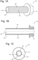
- FIG. 1A is a perspective view of nut 100
- FIG. 1B is a cross-sectional view of nut 100
- FIG. 1C is an end view of nut 100.
- Nut 100 includes sleeve 102 having exterior surface 104 and hollow interior 106 and bevel 108.
- the nut further includes nut head 110.
- Nut 100 is shown with a hexagonal nut head 110, but a person of skill in the art will understand that nut head 110 can be any shape, such as square, domed, round, flat, etc.
- Sleeve 102 includes an exterior surface 104.
- Exterior surface 104 may include a texture which can extend over all or just part of exterior surface 104.
- the texture may extend from a middle of sleeve 102 to one end of sleeve 102.
- sleeve 102 has bevel 108 at one end of sleeve 102, which can help with insertion of sleeve 102 into a hole or cavity of a receiving part for forming a bolted joint.
- Sleeve 102 is typically hollow and includes hollow interior 106, which is typically cylindrical and extends through the length of sleeve 102. Hollow interior 106 may be sized and configured to fit around a shank of the bolt or a threaded length of the bolt.
- the length of sleeve 102 may vary but is typically 0,5 to 3 times the diameter of the bolt for which it is intended to be used.
- Sleeve 102 may be formed from steel, phosphorus steel, aluminum, plastic or any other material appropriate for the desired assembly depending on assembly requirements.
- nut 100 would be integrally formed, for example, from cutting, stamping, machining, moulding, pressing, printing, or any other suitable method. Texturing of exterior surface 104 could be done by shot peening, knurling, etching, pressing or any other suitable method.
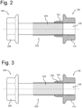
- FIG. 2 is a cross-sectional view of nut 100 in combination with bolt 200.
- Nut 100 includes hollow interior 106 configured to receive bolt shaft 202 of bolt 200.
- Nut 100 includes nut head 110 which further includes threads configured to engage with the threaded portion 204 of bolt shaft 202.
- Nut 100 also includes sleeve 102.
- Hollow interior 106 extends through sleeve 102 and nut head 110 such that hollow interior 106 can receive bolt shaft 202.
- a tool may rotate bolt 200 at bolt head 206 such that threads of the threaded portion 204 of bolt shaft 202 engage with the threads of nut head 110.
- FIG. 3 is a cross-sectional view of nut 100 in combination with bolt 200 similar to the combination of FIG. 2 .
- Nut 100 includes hollow interior 106 configured to receive bolt shaft 202 of bolt 200.
- Nut 100 includes nut head 110 which further includes threads configured to engage with the threaded portion 204 of bolt shaft 202.
- Nut 100 may further include threads 300 which extend through hollow interior 106 and continue form the threads of nut head 110.
- a tool may rotate bolt 200 at bolt head 206 such that threads of the threaded portion 204 of bolt shaft 202 further engages with the threads 300 of sleeve 102 and extend to the threads of nut head 110.
- FIGS. 4A - 4F are views of exemplary exterior surfaces 104 of sleeve 102. These surfaces are examples of surfaces that may create a mechanical locking function in a bolted joint. These examples should be in no way limiting of the type of textured exterior surface capable of generating friction and/or a mechanical lock between sleeve 102 and a receiving part.
- FIG. 4A illustrates a knurled exterior surface 104.
- FIG. 4B illustrates a serrated exterior surface 104.
- FIG. 4C illustrates a spiraled serrated exterior surface 104.
- FIG. 4D illustrates a hatched exterior surface 104.
- FIG. 4E illustrates a bumped exterior surface 104.
- FIG. 4F illustrates a smooth exterior surface 104.
- Exterior surfaces 104 of FIGS. 4A - 4F generate a mechanical lock between the nut and one or more receiving parts of an assembly. Exterior surface 104 may depend on the material of the nut and/or the material of the receiving part. It should be understood that exterior surface 104 may have a texture not pictured in FIGS. 4A - 4F .
- FIG. 5 illustrates a cross-sectional view of assembly 500 including nut 100 and bolt 200.
- Assembly 500 includes first receiving part 502 and second receiving part 506.
- Receiving part 504 may be a third receiving part or may be an opposite end of the same receiving part as first receiving part 502.
- Assembly 500 may be configured to receive bolt 200 such that bolt shaft 202 extends through receiving parts 502, 504, 506.
- Assembly 500 may be further configured to receive nut 100 such that sleeve 102 extends through at least receiving part 502 and 506.
- sleeve 102 may be configured to align an opening of receiving part 502 and an opening of receiving part 506 so that assembly 500 is in a desired configuration.
- Nut 100 may be configured such that sleeve 102 is press fit into receiving parts 502 and 506. This eliminates the need for clearance for a tool at the nut end of assembly 500.
- the press fit fixes nut 100 such that it will not rotate or minimally rotate when receiving bolt 200. As bolt 200 rotates, the threaded portion of the bolt shaft engages with the threads 300 of nut 100 without rotating.
- Nut 100 is configured to receive bolt 200 such the threads of bolt 200 engage with the threads 300 of nut 100. Threads 300 may extend through all or part of hollow interior 106. As bolt 200 rotates and engages with threads 300 and nut 100 and bolt 200 tighten, nut 100 may minimally rotate.
- the mechanical lock minimizes or prevents the bolted joint from loosening or slipping by absorbing at least some of the shear forces acting on the bolted joint.
- Combing nut 100 and bolt 200 may only require clearance for a tool to rotate bolt 200 at the bolt head end of assembly 500.
- Bolt 200 may enter assembly 500 at an opening of receiving part 504.
- Sleeve 102 may horizontally align bolt shaft 202 in assembly 500.
- the opening at receiving part 504 may be larger than a circumference of the threaded portion of bolt shaft 202. This allows easier insertion of bolt 200 into assembly 500.
- a tool configured to rotate bolt 200 may engage or disengage bolt 200 to or from nut 100.
- rotating bolt 200 clockwise may move bolt 200 in direction 510 and rotating bolt 200 counterclockwise may move bolt in direction 520.
- Direction 510 may be a tightening direction and direction 520 may be a loosening direction.
- a portion of bolt shaft 202 nearest bolt head 206 may have a larger circumference than the threaded portion of bolt shaft 202.
- the larger circumference my include serrations such as may be found in a serration screw.
- a portion of the shank of the bolt shaft may be configured contact receiving part 504. The bolt shank may tightly insert into an opening of receiving part 504 such that receiving part 504 is aligned with receiving parts 502 and 506.
- the contact between the bolt shank of bolt 200 may generate a further mechanical lock at the bolt end of assembly 500.
- the mechanical lock created between nut 100 and receiving parts 502 and 506 creates a bolted joint that is more resistant to shear forces.
- Nut 100 reduces the area that shear forces can act on a bolt, thus reducing the overall shear forces acting on the bolt.
- the bolted joint is less likely to slip as compared to a conventional bolted joint.
- a bolted joint in a motor or engine may be subject to shear forces during operation. Over time, the shear forces may loosen the bolted joint.
- Incorporating nut 100 into bolted joint reduces the shear area of the bolted joint such that less shear forces are acting on the bolt which minimizes or prevents slippage of the. This in turn may reduce overall maintenance needed on an assembly such as a motor or engine.
- nut 100 reduces the amount of shear forces acting on a bolt of a bolted joint as compared to using conventional nuts, bolt size may be reduced without affecting performance.
- a conventional M14 bolt in an assembly may be reduced to an M12 bolt with nut 100 because the M12 bolt with nut 100 can tolerate equal or greater shear forces than a convention M14 bolt.
- Reducing bolt size in combination with nut 100 may reduce the overall weight of an assembly. For example, using an M12 bolt with nut 100 instead of a conventional M14 bolt. For M12 and M14 bolts with a nominal reference dimension of 90, an M12 bolt may wight 95 grams as compared to the weight of an M14 bolt of 134 grams. If an assembly requires 10 M14 bolts, they may replace with a M12 bolt in combination with nut 100. This would result in a reduced assembly weight of about 390 grams for an assembly that requires 10 bolts. It should be understood that assemblies requiring more bolts will have a greater reduction in weight and assemblies requiring less bolts will have a lesser reduction in weight. Including nut 100 may have the potential to reduce weight by 25 - 30% of bolt and nut combinations. Additionally, surround parts or mating parts of an assembly mays also be reduced.
- Nut 100 in combination with bolt 200 may align receiving parts of an assembly and created bolted joints with a mechanical lock to prevent or minimize slipping from shear forces acting upon the bolt joints.
- a vehicle in motion may have shear forces acting upon the bolted joints of the vehicle.
Landscapes
- Engineering & Computer Science (AREA)
- General Engineering & Computer Science (AREA)
- Mechanical Engineering (AREA)
- Connection Of Plates (AREA)
Abstract
Description
- The present disclosure relates to the fastener field, in particular nuts having sleeves used in conjunction with bolts or screws in an assembly.
- Bolts and screws may join one or more receiving parts at a bolted joint or a screw joint. For brevity, the term bolt will be used to mean a bolt or a screw. Additionally, the term bolted joint will be used to mean a bolted joint or a screw joint.
- A serration bolt may have serrations on its shank to create a locking feature at the bolted joint and therefore avoid slipping. The serrations may avoid slipping by creating a clamping force at the bolted joint. Generally, the larger the bolt the larger the clamping force it can generate. Serration bolts, having serrations on its shank, have been used to downsize bolts while maintaining the necessary clamping force at the bolted joint when assembling receiving parts.
- However, serration bolts require access to both sides of a receiving part during assembly. For example, a first side of the assembly may require enough clearance to insert the serration bolt and a second side of the assembly may require enough clearance for a tightening tool to fully assemble the receiving part(s) with the serration bolt.
- There is a trend to make things smaller and more compact. For example, vehicle engines have become compact, which reduces the space for access to the tip of a bolt or the head of a bolt needed to assemble the engine. Once the bolt is in its final position, it may be difficult to access the bolt at both ends to loosen or tighten it.
- Additionally, the bolted joint may be subject to shear forces which make the bolt slip. To withstand the shear forces and prohibit the bolt from slipping, one may use larger bolts to generate more friction or clamping force, as compared to a smaller bolt, and prevent the bolt from slipping. However, larger bolts are in conflict with the trend to make things smaller and more compact.
- The background section relating to using serration bolts in the assembly of receiving part(s) is merely intended to provide a contextual overview of some current issues and is not intended to be exhaustive. Other contextual information may become apparent to a person of skill in the art upon review of the following detailed description.
- According to an embodiment, a nut may include a sleeve extending perpendicularly from a nut head the nut and configured to extend into a first receiving part and a second receiving part, wherein the sleeve includes; an exterior surface configured to engage with the first receiving part and the second receiving part; and a hollow interior configured to receive a bolt shaft, wherein the sleeve aligns the first receiving part and the second receiving part. The sleeve may be configured to press fit into the first receiving part and the second receiving part such that the nut does not easily rotate, and the exterior surface generates a mechanical lock between the nut, the first receiving part, and the second receiving part.
- A nut with a sleeve configured to press fit into one or more receiving parts generates an interference between the sleeve of the nut and the receiving parts in which the sleeve of the nut is forced into an opening of the receiving parts.
- The sleeve of the nut may extend through the receiving parts to align the receiving parts such that they are assembled into a desired position.
- The exterior surface of a sleeve of the nut may create a mechanical lock between the sleeve receiving parts. The sleeve helps to support a bolt used in assembling the receiving part and reduces the load of shear forces acting upon the bolt. This may help minimize or prevent slippage. In particular, the exterior surface of the sleeve creates friction or clamping forces between the sleeve and a surface of the receiving parts. The sleeve reduces the shear area to which the bolt is exposed and reduces the exposure of a bolt to shear forces.
- The mechanical lock of the sleeve may shield a bolted joint from shear forces. This allows an assembly to reduce the size of bolts due to the reduced shear forces acting on the bolted joint. Reducing bolt size can be done without sacrificing clamping force because, as compared to a conventional nut, the mechanical lock reduces the need of a high clamping force. Therefore, such an assembly may replace conventional nuts with nuts including a sleeve because the sleeve may shield the bolted joint from shear forces. Reducing the bolt sizes in an assembly may reduce cost, materials and weight of an assembly.
- The nut with sleeve may be used in combination with a serrated bolt to generate a mechanical lock at both bolted joints.
- Including a nut with a sleeve can further reduce part handling and piece price because the reduced bolt size requires less assembly torque as compared to a larger bolt. As a result, there is a potential for using smaller tools during assembly.
- According to an embodiment, the hollow interior of the sleeve is threaded. The threads of the hollow interior are configured to engage with the threaded portion of a bolt shaft. Such an engagement between the sleeve of the nut and the bolt generates a stronger connection between the nut and the bolt as compared to a sleeve of a nut without threads.
- According to an embodiment, the exterior surface of the sleeve is configured to generate a mechanical lock between the sleeve, the first receiving part, and the second receiving part. Such a mechanical lock may minimize or prevent slipping at the bolted.
- According to an embodiment, the nut is formed of a ferrous material. Ferrous materials, such as phosphorous steel, are strong and cost-effective materials that may be suitable for vehicle parts. Other materials may be suitable for other applications. In addition to being strong and cost effective, ferrous materials are readily available. Nuts made of ferrous materials are able to generate a strong mechanical lock between the sleeve of the nut and a receiving part thereby helping to reduce the shear forces that may act upon a bolt or screw.
- According to an embodiment, the sleeve of the nut includes an exterior surface that is knurled and/or includes serrations. Such a knurled exterior surface creates friction and/or clamping forces between the sleeve and a receiving part of an assembly, and therefore may create a mechanical lock between the sleeve and a receiving part. Such a mechanical lock between the sleeve and the receiving part allows the sleeve to absorb shear forces that would otherwise act on the bolted joint. The friction, locking and/or clamping force helps to minimize or prevents slippage. The sleeve may include other textures on the exterior surface capable of providing the necessary friction and/or clamping force.
- According to an embodiment, the exterior surface of the sleeve of the nut may be smooth. Such a smooth surface may make it easier to insert the nut into receiving parts as compared to a nut with a knurled exterior surface while still generating a mechanical lock between the sleeve and the receiving parts.
- According to an embodiment, a circumference of the sleeve is configured to insert into a first opening of the first receiving part and a second opening of the second receiving part, and the exterior surface is in contact with the first receiving part and the second receiving part. The contact between the exterior surface of the sleeve and the receiving parts is such that it ensures a mechanical lock between the nut and the receiving parts.
- According to an embodiment, the nut is fixed as the bolt shaft of a bolt engages with the nut. The nut may be fixed because of friction forces acting between the exterior surface of the sleeve of the nut and the receiving parts. Once the nut is inserted into the receiving parts the fixed nut allows tightening of the bolt without access to the nut side of the assembly. As the bolt rotates and engages with the threads of the nut, the receiving parts are assembled with a single tightening tool acting upon a head of the bolt.
- According to an embodiment, an assembly may include a nut as previously described. The assembly may further include a first receiving part; a second receiving part; and a bolt, wherein a sleeve of the nut enters the assembly at the first receiving part and extends through to the second receiving part, and wherein the bolt enters a hollow interior of the sleeve at the second receiving part. The sleeve of the nut extends through both receiving parts to align the receiving parts into a desired configuration. The bolt may be inserted into the second receiving part such that an opening of the second receiving part may be larger than the circumference of at least a portion of the bolt shaft. Such an opening at the second receiving part enables the bolt to enter the assembly at a desired alignment with the nut.
- A method of assembling an assembly with the nut as previously described and a bolt allows the bolt to be tightened or loosened without disturbing the mechanical lock between the sleeve of the nut and the receiving part.
- According to an embodiment, the bolt is configured to rotate to engage with the nut. This allows assembling of the assembly from a head of the bolt. Rotating the bolt engages a threaded portions of the bolt shaft with the threads of the nut.
- According to an embodiment, the assembly includes a clearance for a tightening tool at a head of the bolt, wherein the tightening tool rotates the bolt to engage the nut and assemble the assembly hollow interior of the sleeve. The clearance ensures access to the bolt head to tighten or loosen the bolt with a tool.
- According to an embodiment, the bolt is a serrated bolt such that a portion of a bolt shank of the bolt includes serrations to engage with the second receiving part. This allows the serrations of the bolt to engage with a second receiving part and generate a further mechanical lock. For example, a conventional serrated bolt or a preassembled bolt such as those described in FIGS.2A-2D of application
EP 23207472.4 EP 24159985.1 - According to an embodiment, the bolt is configured to generate a further mechanical lock. Such that at least a portion of the bolt shank comes into contact with the receiving part at an end of the assembly opposite the nut. The contact between the portion of the bolt shank and the second receiving part generates another mechanical lock which further reduces or prevents slipping.
- According to an embodiment, the opening of the second receiving part is greater than the circumference of at least a portion of a shaft of the bolt. This allows for insertion of the bolt into the assembly. The circumference of the shank of the bolt may be larger than the rest of the bolt shaft to engage with the second receiving part.
- The present disclosure will now be described in further detail with reference to the drawings that shows one embodiment of the present disclosure:
-
FIG. 1A is a perspective view of a nut with a sleeve to create a locking function according to at least one example of the disclosure; -
FIG. 1B is a cross-sectional view of the sleeve ofFIG. 1A ; -
FIG. 1C is an end view of the sleeve ofFIG. 1A ; -
FIG. 2 is a cross-sectional view of a nut with a sleeve mated with a bolt; -
FIG. 3 is a cross-sectional view of a nut with a threaded sleeve mated with a bolt; -
FIGS. 4A - 4F are perspective views of nuts with sleeves with different surface textures of the exterior surface; -
FIG. 5 is a cross sectional view of the nut with a sleeve connected to a bolt to assemble an assembly. - The present disclosure is directed to a nut with a sleeve for use with a fasteners such as bolts and/or screws. The nut includes a sleeve with an exterior surface configured to generate a mechanical lock between the sleeve and a receiving part of an assembly and can have any number of different surface textures including but not limited to smooth, dimples, rough turned, serrations, a knurled surface, spiral serrations, a hatched surface, and a pattern of bumps. The nut may be used with a bolt to create a bolted joint in assembling one or more receiving parts.
-
FIG. 1A is a perspective view ofnut 100,FIG. 1B is a cross-sectional view ofnut 100 andFIG. 1C is an end view ofnut 100.Nut 100 includessleeve 102 havingexterior surface 104 andhollow interior 106 andbevel 108. The nut further includesnut head 110.Nut 100 is shown with ahexagonal nut head 110, but a person of skill in the art will understand thatnut head 110 can be any shape, such as square, domed, round, flat, etc. -
Sleeve 102 includes anexterior surface 104.Exterior surface 104 may include a texture which can extend over all or just part ofexterior surface 104. For example, the texture may extend from a middle ofsleeve 102 to one end ofsleeve 102. In some embodiments (including that shown inFigs. 1A-1C ),sleeve 102 has bevel 108 at one end ofsleeve 102, which can help with insertion ofsleeve 102 into a hole or cavity of a receiving part for forming a bolted joint.Sleeve 102 is typically hollow and includeshollow interior 106, which is typically cylindrical and extends through the length ofsleeve 102.Hollow interior 106 may be sized and configured to fit around a shank of the bolt or a threaded length of the bolt. - The length of
sleeve 102 may vary but is typically 0,5 to 3 times the diameter of the bolt for which it is intended to be used. -
Sleeve 102 may be formed from steel, phosphorus steel, aluminum, plastic or any other material appropriate for the desired assembly depending on assembly requirements. - Typically,
nut 100 would be integrally formed, for example, from cutting, stamping, machining, moulding, pressing, printing, or any other suitable method. Texturing ofexterior surface 104 could be done by shot peening, knurling, etching, pressing or any other suitable method. -
FIG. 2 is a cross-sectional view ofnut 100 in combination withbolt 200.Nut 100 includeshollow interior 106 configured to receivebolt shaft 202 ofbolt 200.Nut 100 includesnut head 110 which further includes threads configured to engage with the threadedportion 204 ofbolt shaft 202. -
Nut 100 also includessleeve 102.Hollow interior 106 extends throughsleeve 102 andnut head 110 such thathollow interior 106 can receivebolt shaft 202. - A tool may rotate
bolt 200 atbolt head 206 such that threads of the threadedportion 204 ofbolt shaft 202 engage with the threads ofnut head 110. -
FIG. 3 is a cross-sectional view ofnut 100 in combination withbolt 200 similar to the combination ofFIG. 2 .Nut 100 includeshollow interior 106 configured to receivebolt shaft 202 ofbolt 200.Nut 100 includesnut head 110 which further includes threads configured to engage with the threadedportion 204 ofbolt shaft 202.Nut 100 may further includethreads 300 which extend throughhollow interior 106 and continue form the threads ofnut head 110. - A tool may rotate
bolt 200 atbolt head 206 such that threads of the threadedportion 204 ofbolt shaft 202 further engages with thethreads 300 ofsleeve 102 and extend to the threads ofnut head 110. -
FIGS. 4A - 4F are views of exemplaryexterior surfaces 104 ofsleeve 102. These surfaces are examples of surfaces that may create a mechanical locking function in a bolted joint. These examples should be in no way limiting of the type of textured exterior surface capable of generating friction and/or a mechanical lock betweensleeve 102 and a receiving part. -
FIG. 4A illustrates a knurledexterior surface 104. -
FIG. 4B illustrates a serratedexterior surface 104. -
FIG. 4C illustrates a spiraled serratedexterior surface 104. -
FIG. 4D illustrates a hatchedexterior surface 104. -
FIG. 4E illustrates a bumpedexterior surface 104. -
FIG. 4F illustrates a smoothexterior surface 104. - Exterior surfaces 104 of
FIGS. 4A - 4F generate a mechanical lock between the nut and one or more receiving parts of an assembly.Exterior surface 104 may depend on the material of the nut and/or the material of the receiving part. It should be understood thatexterior surface 104 may have a texture not pictured inFIGS. 4A - 4F . -
FIG. 5 illustrates a cross-sectional view ofassembly 500 includingnut 100 andbolt 200.Assembly 500 includes first receivingpart 502 and second receivingpart 506. Receivingpart 504 may be a third receiving part or may be an opposite end of the same receiving part as first receivingpart 502.Assembly 500 may be configured to receivebolt 200 such thatbolt shaft 202 extends through receivingparts Assembly 500 may be further configured to receivenut 100 such thatsleeve 102 extends through at least receivingpart - For example,
sleeve 102 may be configured to align an opening of receivingpart 502 and an opening of receivingpart 506 so thatassembly 500 is in a desired configuration. -
Nut 100 may be configured such thatsleeve 102 is press fit into receivingparts assembly 500. The press fit fixesnut 100 such that it will not rotate or minimally rotate when receivingbolt 200. Asbolt 200 rotates, the threaded portion of the bolt shaft engages with thethreads 300 ofnut 100 without rotating. - The press fit of
sleeve 102 putsexterior surface 104 in contact with receivingparts nut 100, and receivingparts Nut 100 is configured to receivebolt 200 such the threads ofbolt 200 engage with thethreads 300 ofnut 100.Threads 300 may extend through all or part ofhollow interior 106. Asbolt 200 rotates and engages withthreads 300 andnut 100 and bolt 200 tighten,nut 100 may minimally rotate. - The contact between
exterior surface 104 and receivingparts nut 100 and receivingparts - Combing
nut 100 and bolt 200 may only require clearance for a tool to rotatebolt 200 at the bolt head end ofassembly 500.Bolt 200 may enterassembly 500 at an opening of receivingpart 504.Sleeve 102 may horizontally alignbolt shaft 202 inassembly 500. - The opening at receiving
part 504 may be larger than a circumference of the threaded portion ofbolt shaft 202. This allows easier insertion ofbolt 200 intoassembly 500. - A tool configured to rotate
bolt 200 may engage or disengagebolt 200 to or fromnut 100. For example, rotatingbolt 200 clockwise may movebolt 200 indirection 510 androtating bolt 200 counterclockwise may move bolt indirection 520.Direction 510 may be a tightening direction anddirection 520 may be a loosening direction. - A portion of
bolt shaft 202nearest bolt head 206 may have a larger circumference than the threaded portion ofbolt shaft 202. The larger circumference my include serrations such as may be found in a serration screw. Asbolt 200 moves indirection 510, a portion of the shank of the bolt shaft may be configuredcontact receiving part 504. The bolt shank may tightly insert into an opening of receivingpart 504 such that receivingpart 504 is aligned with receivingparts - Additionally, the contact between the bolt shank of
bolt 200 may generate a further mechanical lock at the bolt end ofassembly 500. - The mechanical lock created between
nut 100 and receivingparts Nut 100 reduces the area that shear forces can act on a bolt, thus reducing the overall shear forces acting on the bolt. As a result, the bolted joint is less likely to slip as compared to a conventional bolted joint. For example, a bolted joint in a motor or engine may be subject to shear forces during operation. Over time, the shear forces may loosen the bolted joint. Incorporatingnut 100 into bolted joint reduces the shear area of the bolted joint such that less shear forces are acting on the bolt which minimizes or prevents slippage of the. This in turn may reduce overall maintenance needed on an assembly such as a motor or engine. - Because
nut 100 reduces the amount of shear forces acting on a bolt of a bolted joint as compared to using conventional nuts, bolt size may be reduced without affecting performance. For example, depending on the assembly environment, a conventional M14 bolt in an assembly may be reduced to an M12 bolt withnut 100 because the M12 bolt withnut 100 can tolerate equal or greater shear forces than a convention M14 bolt. - Reducing bolt size in combination with
nut 100 may reduce the overall weight of an assembly. For example, using an M12 bolt withnut 100 instead of a conventional M14 bolt. For M12 and M14 bolts with a nominal reference dimension of 90, an M12 bolt may wight 95 grams as compared to the weight of an M14 bolt of 134 grams. If an assembly requires 10 M14 bolts, they may replace with a M12 bolt in combination withnut 100. This would result in a reduced assembly weight of about 390 grams for an assembly that requires 10 bolts. It should be understood that assemblies requiring more bolts will have a greater reduction in weight and assemblies requiring less bolts will have a lesser reduction in weight. Includingnut 100 may have the potential to reduce weight by 25 - 30% of bolt and nut combinations. Additionally, surround parts or mating parts of an assembly mays also be reduced. -
Nut 100 in combination withbolt 200, such as a serrated bolt, may align receiving parts of an assembly and created bolted joints with a mechanical lock to prevent or minimize slipping from shear forces acting upon the bolt joints. For example, a vehicle in motion may have shear forces acting upon the bolted joints of the vehicle. - While the present disclosure has been described with reference to exemplary embodiments, it will be understood by those skilled in the art that various changes may be made, and equivalents may be substituted for elements thereof without departing from the scope of the present disclosure. In addition, many modifications may be made to adapt a particular situation or material to the teachings of the present disclosure without departing from the essential scope thereof. Therefore, it is intended that the present disclosure not be limited to the particular embodiments disclosed, but that the present disclosure will include all embodiments falling within the scope of the appended claims.
Claims (15)
- A nut (100) comprising:
a sleeve (102) extending from a nut head (110) the nut (100) and configured to extend into a first receiving part (502) and a second receiving part (506), wherein the sleeve comprises;an exterior surface (104) configured to engage with the first receiving part (502) and the second receiving part (506); anda hollow interior (106) configured to receive a bolt shaft (202),wherein the sleeve aligns the first receiving part (502) and the second receiving part (506). - The nut (100) of claim 1, wherein the hollow interior is threaded.
- The nut (100) of claim 2, wherein the hollow interior (106) is and further configured to engage with a threaded portion (204) of the bolt shaft (202).
- The nut (100) of any of the preceding claims, wherein the exterior surface (104) of the sleeve (102) is configured to generate a mechanical lock between the sleeve (102), the first receiving part (502), and the second receiving part (506).
- The nut (100) of any of the preceding claims, wherein the nut (100) is formed of a ferrous material.
- The nut (100) of any of the preceding claims, wherein the exterior surface (104) is knurled.
- The nut (100) of any of claims 1-5, wherein the exterior surface (104) is smooth.
- The nut (100) of any of the preceding claims, wherein a circumference of the sleeve (102) is configured to insert into a first opening of the first receiving part (502) and a second opening of the second receiving part (506), and wherein the exterior surface (104) is in contact with the first receiving part (502) and the second receiving part (506).
- The nut (100) of claim 8, wherein the nut (100) is fixed as the bolt shaft (202) of a bolt (200) engages with the nut.
- An assembly (500) comprising:a nut (100) according to any of claims 1-9;a first receiving part (502);a second receiving part (506); anda bolt (200), wherein a sleeve (102) of the nut (100) enters the assembly at the first receiving part (502) and extends through to the second receiving part (506), and wherein the bolt (200) enters a hollow interior (106) of the sleeve (102).
- The assembly (500) of claim 10, wherein the bolt (200) is configured to rotate to engage with the nut (100).
- The assembly (500) of claim 10 or 11, further comprising a clearance for a tightening tool at a bolt head (206) of the bolt (200), wherein the tightening tool rotates the bolt (200) to engage the nut (100) and assemble the assembly (500).
- The assembly (500) of any of the preceding claims, wherein the bolt (200) is a serrated bolt .
- The assembly (500) of any of the preceding claims, wherein the bolt (200) is configured to generate a further mechanical lock.
- The assembly of any of the preceding claims, wherein an opening of the second receiving part (506) is greater than the circumference of at least a portion of a bolt shaft (202) of the bolt (200).
Priority Applications (1)
| Application Number | Priority Date | Filing Date | Title |
|---|---|---|---|
| PCT/EP2024/080936 WO2025093741A1 (en) | 2023-11-02 | 2024-11-01 | Cylindrical sleeve with extra features for alignment |
Applications Claiming Priority (2)
| Application Number | Priority Date | Filing Date | Title |
|---|---|---|---|
| EP23207472.4A EP4549761A1 (en) | 2023-11-02 | 2023-11-02 | Combined washer with extra features for alignment |
| EP24159985.1A EP4549762A1 (en) | 2023-11-02 | 2024-02-27 | Bolt sleeve with extra features for alignment |
Publications (1)
| Publication Number | Publication Date |
|---|---|
| EP4549758A1 true EP4549758A1 (en) | 2025-05-07 |
Family
ID=90361512
Family Applications (1)
| Application Number | Title | Priority Date | Filing Date |
|---|---|---|---|
| EP24162167.1A Pending EP4549758A1 (en) | 2023-11-02 | 2024-03-07 | Nut sleeve with locking and alignment features |
Country Status (1)
| Country | Link |
|---|---|
| EP (1) | EP4549758A1 (en) |
Citations (2)
| Publication number | Priority date | Publication date | Assignee | Title |
|---|---|---|---|---|
| US20130108392A1 (en) * | 2011-10-26 | 2013-05-02 | Engineered Components Company | Low profile fastener assembly |
| US20150016919A1 (en) * | 2013-07-09 | 2015-01-15 | Dynamic Fitness & Strength, LLC | Fastener For Fitness Apparatus |
-
2024
- 2024-03-07 EP EP24162167.1A patent/EP4549758A1/en active Pending
Patent Citations (2)
| Publication number | Priority date | Publication date | Assignee | Title |
|---|---|---|---|---|
| US20130108392A1 (en) * | 2011-10-26 | 2013-05-02 | Engineered Components Company | Low profile fastener assembly |
| US20150016919A1 (en) * | 2013-07-09 | 2015-01-15 | Dynamic Fitness & Strength, LLC | Fastener For Fitness Apparatus |
Similar Documents
| Publication | Publication Date | Title |
|---|---|---|
| US6227782B1 (en) | Self-locking threaded fastener assembly | |
| CN1457401B (en) | Anti-loosening fasteners | |
| EP1071543B1 (en) | High torque wrenching system | |
| CA1311146C (en) | Swaged collar fastener | |
| US5544991A (en) | Locking frustrum nut | |
| EP1184581A2 (en) | Threaded fastener | |
| JP2004505218A (en) | Fastener | |
| EP0786603B1 (en) | Self-locking preload controlling nut | |
| US5538378A (en) | Self-locking threaded connecting device | |
| KR20020026796A (en) | Screw member | |
| KR102283353B1 (en) | Lock nut | |
| US20030072633A1 (en) | Torque prevailing stud | |
| US20020104187A1 (en) | Metal insert component | |
| EP4549762A1 (en) | Bolt sleeve with extra features for alignment | |
| EP4660467A1 (en) | Bolt sleeve with extra guiding feature of serration sleeves on screws | |
| JP4094818B2 (en) | Fasteners, fastener systems, and tools for use in fastener systems | |
| GB2309504A (en) | Stabiliser means for a motor vehicle suspension | |
| JP2000257620A (en) | Lock nut structure | |
| AU689897B2 (en) | Self-locking threaded connecting device | |
| WO2025093741A1 (en) | Cylindrical sleeve with extra features for alignment | |
| JP2509446B2 (en) | How to fix screws to metal plate | |
| EP4158206B1 (en) | A fastening element and a vehicle arrangement | |
| AU2022277963B2 (en) | Attachment arrangement for composite wheels | |
| JPH10141349A (en) | Locking nut and manufacturing method thereof | |
| EP4535571A1 (en) | Grounding contact and method for assembling a ground cable and a component |
Legal Events
| Date | Code | Title | Description |
|---|---|---|---|
| PUAI | Public reference made under article 153(3) epc to a published international application that has entered the european phase |
Free format text: ORIGINAL CODE: 0009012 |
|
| STAA | Information on the status of an ep patent application or granted ep patent |
Free format text: STATUS: THE APPLICATION HAS BEEN PUBLISHED |
|
| AK | Designated contracting states |
Kind code of ref document: A1 Designated state(s): AL AT BE BG CH CY CZ DE DK EE ES FI FR GB GR HR HU IE IS IT LI LT LU LV MC ME MK MT NL NO PL PT RO RS SE SI SK SM TR |
|
| STAA | Information on the status of an ep patent application or granted ep patent |
Free format text: STATUS: REQUEST FOR EXAMINATION WAS MADE |
|
| 17P | Request for examination filed |
Effective date: 20251107 |
|
| STAA | Information on the status of an ep patent application or granted ep patent |
Free format text: STATUS: EXAMINATION IS IN PROGRESS |
|
| 17Q | First examination report despatched |
Effective date: 20260312 |