EP4549751A1 - Fluid control device, fluid pressure supply apparatus, and fluid control method - Google Patents
Fluid control device, fluid pressure supply apparatus, and fluid control method Download PDFInfo
- Publication number
- EP4549751A1 EP4549751A1 EP22949367.1A EP22949367A EP4549751A1 EP 4549751 A1 EP4549751 A1 EP 4549751A1 EP 22949367 A EP22949367 A EP 22949367A EP 4549751 A1 EP4549751 A1 EP 4549751A1
- Authority
- EP
- European Patent Office
- Prior art keywords
- valve
- fluid
- pressure adjusting
- pressure
- adjusting valve
- Prior art date
- Legal status (The legal status is an assumption and is not a legal conclusion. Google has not performed a legal analysis and makes no representation as to the accuracy of the status listed.)
- Pending
Links
Images





Classifications
-
- F—MECHANICAL ENGINEERING; LIGHTING; HEATING; WEAPONS; BLASTING
- F15—FLUID-PRESSURE ACTUATORS; HYDRAULICS OR PNEUMATICS IN GENERAL
- F15B—SYSTEMS ACTING BY MEANS OF FLUIDS IN GENERAL; FLUID-PRESSURE ACTUATORS, e.g. SERVOMOTORS; DETAILS OF FLUID-PRESSURE SYSTEMS, NOT OTHERWISE PROVIDED FOR
- F15B11/00—Servomotor systems without provision for follow-up action; Circuits therefor
- F15B11/08—Servomotor systems without provision for follow-up action; Circuits therefor with only one servomotor
- F15B11/10—Servomotor systems without provision for follow-up action; Circuits therefor with only one servomotor in which the servomotor position is a function of the pressure also pressure regulators as operating means for such systems, the device itself may be a position indicating system
-
- G—PHYSICS
- G05—CONTROLLING; REGULATING
- G05D—SYSTEMS FOR CONTROLLING OR REGULATING NON-ELECTRIC VARIABLES
- G05D16/00—Control of fluid pressure
- G05D16/20—Control of fluid pressure characterised by the use of electric means
- G05D16/2006—Control of fluid pressure characterised by the use of electric means with direct action of electric energy on controlling means
- G05D16/2013—Control of fluid pressure characterised by the use of electric means with direct action of electric energy on controlling means using throttling means as controlling means
- G05D16/2026—Control of fluid pressure characterised by the use of electric means with direct action of electric energy on controlling means using throttling means as controlling means with a plurality of throttling means
- G05D16/2033—Control of fluid pressure characterised by the use of electric means with direct action of electric energy on controlling means using throttling means as controlling means with a plurality of throttling means the plurality of throttling means being arranged in series
-
- F—MECHANICAL ENGINEERING; LIGHTING; HEATING; WEAPONS; BLASTING
- F15—FLUID-PRESSURE ACTUATORS; HYDRAULICS OR PNEUMATICS IN GENERAL
- F15B—SYSTEMS ACTING BY MEANS OF FLUIDS IN GENERAL; FLUID-PRESSURE ACTUATORS, e.g. SERVOMOTORS; DETAILS OF FLUID-PRESSURE SYSTEMS, NOT OTHERWISE PROVIDED FOR
- F15B20/00—Safety arrangements for fluid actuator systems; Applications of safety devices in fluid actuator systems; Emergency measures for fluid actuator systems
-
- F—MECHANICAL ENGINEERING; LIGHTING; HEATING; WEAPONS; BLASTING
- F15—FLUID-PRESSURE ACTUATORS; HYDRAULICS OR PNEUMATICS IN GENERAL
- F15B—SYSTEMS ACTING BY MEANS OF FLUIDS IN GENERAL; FLUID-PRESSURE ACTUATORS, e.g. SERVOMOTORS; DETAILS OF FLUID-PRESSURE SYSTEMS, NOT OTHERWISE PROVIDED FOR
- F15B21/00—Common features of fluid actuator systems; Fluid-pressure actuator systems or details thereof, not covered by any other group of this subclass
- F15B21/04—Special measures taken in connection with the properties of the fluid
- F15B21/048—Arrangements for compressed air preparation, e.g. comprising air driers, air condensers, filters, lubricators or pressure regulators
-
- F—MECHANICAL ENGINEERING; LIGHTING; HEATING; WEAPONS; BLASTING
- F15—FLUID-PRESSURE ACTUATORS; HYDRAULICS OR PNEUMATICS IN GENERAL
- F15B—SYSTEMS ACTING BY MEANS OF FLUIDS IN GENERAL; FLUID-PRESSURE ACTUATORS, e.g. SERVOMOTORS; DETAILS OF FLUID-PRESSURE SYSTEMS, NOT OTHERWISE PROVIDED FOR
- F15B21/00—Common features of fluid actuator systems; Fluid-pressure actuator systems or details thereof, not covered by any other group of this subclass
- F15B21/08—Servomotor systems incorporating electrically operated control means
- F15B21/082—Servomotor systems incorporating electrically operated control means with different modes
-
- G—PHYSICS
- G05—CONTROLLING; REGULATING
- G05D—SYSTEMS FOR CONTROLLING OR REGULATING NON-ELECTRIC VARIABLES
- G05D16/00—Control of fluid pressure
- G05D16/20—Control of fluid pressure characterised by the use of electric means
- G05D16/2006—Control of fluid pressure characterised by the use of electric means with direct action of electric energy on controlling means
- G05D16/2066—Control of fluid pressure characterised by the use of electric means with direct action of electric energy on controlling means using controlling means acting on the pressure source
-
- G—PHYSICS
- G05—CONTROLLING; REGULATING
- G05D—SYSTEMS FOR CONTROLLING OR REGULATING NON-ELECTRIC VARIABLES
- G05D7/00—Control of flow
- G05D7/06—Control of flow characterised by the use of electric means
- G05D7/0617—Control of flow characterised by the use of electric means specially adapted for fluid materials
- G05D7/0629—Control of flow characterised by the use of electric means specially adapted for fluid materials characterised by the type of regulator means
- G05D7/0635—Control of flow characterised by the use of electric means specially adapted for fluid materials characterised by the type of regulator means by action on throttling means
-
- G—PHYSICS
- G05—CONTROLLING; REGULATING
- G05D—SYSTEMS FOR CONTROLLING OR REGULATING NON-ELECTRIC VARIABLES
- G05D7/00—Control of flow
- G05D7/06—Control of flow characterised by the use of electric means
- G05D7/0617—Control of flow characterised by the use of electric means specially adapted for fluid materials
- G05D7/0629—Control of flow characterised by the use of electric means specially adapted for fluid materials characterised by the type of regulator means
- G05D7/0635—Control of flow characterised by the use of electric means specially adapted for fluid materials characterised by the type of regulator means by action on throttling means
- G05D7/0641—Control of flow characterised by the use of electric means specially adapted for fluid materials characterised by the type of regulator means by action on throttling means using a plurality of throttling means
- G05D7/0647—Control of flow characterised by the use of electric means specially adapted for fluid materials characterised by the type of regulator means by action on throttling means using a plurality of throttling means the plurality of throttling means being arranged in series
-
- F—MECHANICAL ENGINEERING; LIGHTING; HEATING; WEAPONS; BLASTING
- F15—FLUID-PRESSURE ACTUATORS; HYDRAULICS OR PNEUMATICS IN GENERAL
- F15B—SYSTEMS ACTING BY MEANS OF FLUIDS IN GENERAL; FLUID-PRESSURE ACTUATORS, e.g. SERVOMOTORS; DETAILS OF FLUID-PRESSURE SYSTEMS, NOT OTHERWISE PROVIDED FOR
- F15B2211/00—Circuits for servomotor systems
- F15B2211/30—Directional control
- F15B2211/305—Directional control characterised by the type of valves
- F15B2211/30505—Non-return valves, i.e. check valves
- F15B2211/30515—Load holding valves
-
- F—MECHANICAL ENGINEERING; LIGHTING; HEATING; WEAPONS; BLASTING
- F15—FLUID-PRESSURE ACTUATORS; HYDRAULICS OR PNEUMATICS IN GENERAL
- F15B—SYSTEMS ACTING BY MEANS OF FLUIDS IN GENERAL; FLUID-PRESSURE ACTUATORS, e.g. SERVOMOTORS; DETAILS OF FLUID-PRESSURE SYSTEMS, NOT OTHERWISE PROVIDED FOR
- F15B2211/00—Circuits for servomotor systems
- F15B2211/30—Directional control
- F15B2211/305—Directional control characterised by the type of valves
- F15B2211/3056—Assemblies of multiple valves
- F15B2211/30565—Assemblies of multiple valves having multiple valves for a single output member, e.g. for creating higher valve function by use of multiple valves like two 2/2-valves replacing a 5/3-valve
-
- F—MECHANICAL ENGINEERING; LIGHTING; HEATING; WEAPONS; BLASTING
- F15—FLUID-PRESSURE ACTUATORS; HYDRAULICS OR PNEUMATICS IN GENERAL
- F15B—SYSTEMS ACTING BY MEANS OF FLUIDS IN GENERAL; FLUID-PRESSURE ACTUATORS, e.g. SERVOMOTORS; DETAILS OF FLUID-PRESSURE SYSTEMS, NOT OTHERWISE PROVIDED FOR
- F15B2211/00—Circuits for servomotor systems
- F15B2211/30—Directional control
- F15B2211/365—Directional control combined with flow control and pressure control
-
- F—MECHANICAL ENGINEERING; LIGHTING; HEATING; WEAPONS; BLASTING
- F15—FLUID-PRESSURE ACTUATORS; HYDRAULICS OR PNEUMATICS IN GENERAL
- F15B—SYSTEMS ACTING BY MEANS OF FLUIDS IN GENERAL; FLUID-PRESSURE ACTUATORS, e.g. SERVOMOTORS; DETAILS OF FLUID-PRESSURE SYSTEMS, NOT OTHERWISE PROVIDED FOR
- F15B2211/00—Circuits for servomotor systems
- F15B2211/40—Flow control
- F15B2211/405—Flow control characterised by the type of flow control means or valve
- F15B2211/40515—Flow control characterised by the type of flow control means or valve with variable throttles or orifices
-
- F—MECHANICAL ENGINEERING; LIGHTING; HEATING; WEAPONS; BLASTING
- F15—FLUID-PRESSURE ACTUATORS; HYDRAULICS OR PNEUMATICS IN GENERAL
- F15B—SYSTEMS ACTING BY MEANS OF FLUIDS IN GENERAL; FLUID-PRESSURE ACTUATORS, e.g. SERVOMOTORS; DETAILS OF FLUID-PRESSURE SYSTEMS, NOT OTHERWISE PROVIDED FOR
- F15B2211/00—Circuits for servomotor systems
- F15B2211/40—Flow control
- F15B2211/405—Flow control characterised by the type of flow control means or valve
- F15B2211/40576—Assemblies of multiple valves
-
- F—MECHANICAL ENGINEERING; LIGHTING; HEATING; WEAPONS; BLASTING
- F15—FLUID-PRESSURE ACTUATORS; HYDRAULICS OR PNEUMATICS IN GENERAL
- F15B—SYSTEMS ACTING BY MEANS OF FLUIDS IN GENERAL; FLUID-PRESSURE ACTUATORS, e.g. SERVOMOTORS; DETAILS OF FLUID-PRESSURE SYSTEMS, NOT OTHERWISE PROVIDED FOR
- F15B2211/00—Circuits for servomotor systems
- F15B2211/40—Flow control
- F15B2211/405—Flow control characterised by the type of flow control means or valve
- F15B2211/40576—Assemblies of multiple valves
- F15B2211/40592—Assemblies of multiple valves with multiple valves in parallel flow paths
-
- F—MECHANICAL ENGINEERING; LIGHTING; HEATING; WEAPONS; BLASTING
- F15—FLUID-PRESSURE ACTUATORS; HYDRAULICS OR PNEUMATICS IN GENERAL
- F15B—SYSTEMS ACTING BY MEANS OF FLUIDS IN GENERAL; FLUID-PRESSURE ACTUATORS, e.g. SERVOMOTORS; DETAILS OF FLUID-PRESSURE SYSTEMS, NOT OTHERWISE PROVIDED FOR
- F15B2211/00—Circuits for servomotor systems
- F15B2211/40—Flow control
- F15B2211/415—Flow control characterised by the connections of the flow control means in the circuit
- F15B2211/41509—Flow control characterised by the connections of the flow control means in the circuit being connected to a pressure source and a directional control valve
-
- F—MECHANICAL ENGINEERING; LIGHTING; HEATING; WEAPONS; BLASTING
- F15—FLUID-PRESSURE ACTUATORS; HYDRAULICS OR PNEUMATICS IN GENERAL
- F15B—SYSTEMS ACTING BY MEANS OF FLUIDS IN GENERAL; FLUID-PRESSURE ACTUATORS, e.g. SERVOMOTORS; DETAILS OF FLUID-PRESSURE SYSTEMS, NOT OTHERWISE PROVIDED FOR
- F15B2211/00—Circuits for servomotor systems
- F15B2211/40—Flow control
- F15B2211/415—Flow control characterised by the connections of the flow control means in the circuit
- F15B2211/41572—Flow control characterised by the connections of the flow control means in the circuit being connected to a pressure source and an output member
-
- F—MECHANICAL ENGINEERING; LIGHTING; HEATING; WEAPONS; BLASTING
- F15—FLUID-PRESSURE ACTUATORS; HYDRAULICS OR PNEUMATICS IN GENERAL
- F15B—SYSTEMS ACTING BY MEANS OF FLUIDS IN GENERAL; FLUID-PRESSURE ACTUATORS, e.g. SERVOMOTORS; DETAILS OF FLUID-PRESSURE SYSTEMS, NOT OTHERWISE PROVIDED FOR
- F15B2211/00—Circuits for servomotor systems
- F15B2211/40—Flow control
- F15B2211/42—Flow control characterised by the type of actuation
- F15B2211/426—Flow control characterised by the type of actuation electrically or electronically
-
- F—MECHANICAL ENGINEERING; LIGHTING; HEATING; WEAPONS; BLASTING
- F15—FLUID-PRESSURE ACTUATORS; HYDRAULICS OR PNEUMATICS IN GENERAL
- F15B—SYSTEMS ACTING BY MEANS OF FLUIDS IN GENERAL; FLUID-PRESSURE ACTUATORS, e.g. SERVOMOTORS; DETAILS OF FLUID-PRESSURE SYSTEMS, NOT OTHERWISE PROVIDED FOR
- F15B2211/00—Circuits for servomotor systems
- F15B2211/40—Flow control
- F15B2211/42—Flow control characterised by the type of actuation
- F15B2211/428—Flow control characterised by the type of actuation actuated by fluid pressure
-
- F—MECHANICAL ENGINEERING; LIGHTING; HEATING; WEAPONS; BLASTING
- F15—FLUID-PRESSURE ACTUATORS; HYDRAULICS OR PNEUMATICS IN GENERAL
- F15B—SYSTEMS ACTING BY MEANS OF FLUIDS IN GENERAL; FLUID-PRESSURE ACTUATORS, e.g. SERVOMOTORS; DETAILS OF FLUID-PRESSURE SYSTEMS, NOT OTHERWISE PROVIDED FOR
- F15B2211/00—Circuits for servomotor systems
- F15B2211/50—Pressure control
- F15B2211/505—Pressure control characterised by the type of pressure control means
- F15B2211/50554—Pressure control characterised by the type of pressure control means the pressure control means controlling a pressure downstream of the pressure control means, e.g. pressure reducing valve
-
- F—MECHANICAL ENGINEERING; LIGHTING; HEATING; WEAPONS; BLASTING
- F15—FLUID-PRESSURE ACTUATORS; HYDRAULICS OR PNEUMATICS IN GENERAL
- F15B—SYSTEMS ACTING BY MEANS OF FLUIDS IN GENERAL; FLUID-PRESSURE ACTUATORS, e.g. SERVOMOTORS; DETAILS OF FLUID-PRESSURE SYSTEMS, NOT OTHERWISE PROVIDED FOR
- F15B2211/00—Circuits for servomotor systems
- F15B2211/50—Pressure control
- F15B2211/515—Pressure control characterised by the connections of the pressure control means in the circuit
- F15B2211/5151—Pressure control characterised by the connections of the pressure control means in the circuit being connected to a pressure source and a directional control valve
-
- F—MECHANICAL ENGINEERING; LIGHTING; HEATING; WEAPONS; BLASTING
- F15—FLUID-PRESSURE ACTUATORS; HYDRAULICS OR PNEUMATICS IN GENERAL
- F15B—SYSTEMS ACTING BY MEANS OF FLUIDS IN GENERAL; FLUID-PRESSURE ACTUATORS, e.g. SERVOMOTORS; DETAILS OF FLUID-PRESSURE SYSTEMS, NOT OTHERWISE PROVIDED FOR
- F15B2211/00—Circuits for servomotor systems
- F15B2211/50—Pressure control
- F15B2211/515—Pressure control characterised by the connections of the pressure control means in the circuit
- F15B2211/5158—Pressure control characterised by the connections of the pressure control means in the circuit being connected to a pressure source and an output member
-
- F—MECHANICAL ENGINEERING; LIGHTING; HEATING; WEAPONS; BLASTING
- F15—FLUID-PRESSURE ACTUATORS; HYDRAULICS OR PNEUMATICS IN GENERAL
- F15B—SYSTEMS ACTING BY MEANS OF FLUIDS IN GENERAL; FLUID-PRESSURE ACTUATORS, e.g. SERVOMOTORS; DETAILS OF FLUID-PRESSURE SYSTEMS, NOT OTHERWISE PROVIDED FOR
- F15B2211/00—Circuits for servomotor systems
- F15B2211/50—Pressure control
- F15B2211/52—Pressure control characterised by the type of actuation
- F15B2211/526—Pressure control characterised by the type of actuation electrically or electronically
-
- F—MECHANICAL ENGINEERING; LIGHTING; HEATING; WEAPONS; BLASTING
- F15—FLUID-PRESSURE ACTUATORS; HYDRAULICS OR PNEUMATICS IN GENERAL
- F15B—SYSTEMS ACTING BY MEANS OF FLUIDS IN GENERAL; FLUID-PRESSURE ACTUATORS, e.g. SERVOMOTORS; DETAILS OF FLUID-PRESSURE SYSTEMS, NOT OTHERWISE PROVIDED FOR
- F15B2211/00—Circuits for servomotor systems
- F15B2211/50—Pressure control
- F15B2211/565—Control of a downstream pressure
-
- F—MECHANICAL ENGINEERING; LIGHTING; HEATING; WEAPONS; BLASTING
- F15—FLUID-PRESSURE ACTUATORS; HYDRAULICS OR PNEUMATICS IN GENERAL
- F15B—SYSTEMS ACTING BY MEANS OF FLUIDS IN GENERAL; FLUID-PRESSURE ACTUATORS, e.g. SERVOMOTORS; DETAILS OF FLUID-PRESSURE SYSTEMS, NOT OTHERWISE PROVIDED FOR
- F15B2211/00—Circuits for servomotor systems
- F15B2211/60—Circuit components or control therefor
- F15B2211/63—Electronic controllers
- F15B2211/6303—Electronic controllers using input signals
- F15B2211/632—Electronic controllers using input signals representing a flow rate
- F15B2211/6323—Electronic controllers using input signals representing a flow rate the flow rate being a pressure source flow rate
-
- F—MECHANICAL ENGINEERING; LIGHTING; HEATING; WEAPONS; BLASTING
- F15—FLUID-PRESSURE ACTUATORS; HYDRAULICS OR PNEUMATICS IN GENERAL
- F15B—SYSTEMS ACTING BY MEANS OF FLUIDS IN GENERAL; FLUID-PRESSURE ACTUATORS, e.g. SERVOMOTORS; DETAILS OF FLUID-PRESSURE SYSTEMS, NOT OTHERWISE PROVIDED FOR
- F15B2211/00—Circuits for servomotor systems
- F15B2211/60—Circuit components or control therefor
- F15B2211/635—Circuits providing pilot pressure to pilot pressure-controlled fluid circuit elements
- F15B2211/6355—Circuits providing pilot pressure to pilot pressure-controlled fluid circuit elements having valve means
-
- F—MECHANICAL ENGINEERING; LIGHTING; HEATING; WEAPONS; BLASTING
- F15—FLUID-PRESSURE ACTUATORS; HYDRAULICS OR PNEUMATICS IN GENERAL
- F15B—SYSTEMS ACTING BY MEANS OF FLUIDS IN GENERAL; FLUID-PRESSURE ACTUATORS, e.g. SERVOMOTORS; DETAILS OF FLUID-PRESSURE SYSTEMS, NOT OTHERWISE PROVIDED FOR
- F15B2211/00—Circuits for servomotor systems
- F15B2211/60—Circuit components or control therefor
- F15B2211/665—Methods of control using electronic components
- F15B2211/6653—Pressure control
-
- F—MECHANICAL ENGINEERING; LIGHTING; HEATING; WEAPONS; BLASTING
- F15—FLUID-PRESSURE ACTUATORS; HYDRAULICS OR PNEUMATICS IN GENERAL
- F15B—SYSTEMS ACTING BY MEANS OF FLUIDS IN GENERAL; FLUID-PRESSURE ACTUATORS, e.g. SERVOMOTORS; DETAILS OF FLUID-PRESSURE SYSTEMS, NOT OTHERWISE PROVIDED FOR
- F15B2211/00—Circuits for servomotor systems
- F15B2211/60—Circuit components or control therefor
- F15B2211/665—Methods of control using electronic components
- F15B2211/6654—Flow rate control
-
- F—MECHANICAL ENGINEERING; LIGHTING; HEATING; WEAPONS; BLASTING
- F15—FLUID-PRESSURE ACTUATORS; HYDRAULICS OR PNEUMATICS IN GENERAL
- F15B—SYSTEMS ACTING BY MEANS OF FLUIDS IN GENERAL; FLUID-PRESSURE ACTUATORS, e.g. SERVOMOTORS; DETAILS OF FLUID-PRESSURE SYSTEMS, NOT OTHERWISE PROVIDED FOR
- F15B2211/00—Circuits for servomotor systems
- F15B2211/60—Circuit components or control therefor
- F15B2211/665—Methods of control using electronic components
- F15B2211/6658—Control using different modes, e.g. four-quadrant-operation, working mode and transportation mode
-
- F—MECHANICAL ENGINEERING; LIGHTING; HEATING; WEAPONS; BLASTING
- F15—FLUID-PRESSURE ACTUATORS; HYDRAULICS OR PNEUMATICS IN GENERAL
- F15B—SYSTEMS ACTING BY MEANS OF FLUIDS IN GENERAL; FLUID-PRESSURE ACTUATORS, e.g. SERVOMOTORS; DETAILS OF FLUID-PRESSURE SYSTEMS, NOT OTHERWISE PROVIDED FOR
- F15B2211/00—Circuits for servomotor systems
- F15B2211/80—Other types of control related to particular problems or conditions
- F15B2211/85—Control during special operating conditions
- F15B2211/851—Control during special operating conditions during starting
-
- F—MECHANICAL ENGINEERING; LIGHTING; HEATING; WEAPONS; BLASTING
- F15—FLUID-PRESSURE ACTUATORS; HYDRAULICS OR PNEUMATICS IN GENERAL
- F15B—SYSTEMS ACTING BY MEANS OF FLUIDS IN GENERAL; FLUID-PRESSURE ACTUATORS, e.g. SERVOMOTORS; DETAILS OF FLUID-PRESSURE SYSTEMS, NOT OTHERWISE PROVIDED FOR
- F15B2211/00—Circuits for servomotor systems
- F15B2211/80—Other types of control related to particular problems or conditions
- F15B2211/85—Control during special operating conditions
- F15B2211/853—Control during special operating conditions during stopping
-
- F—MECHANICAL ENGINEERING; LIGHTING; HEATING; WEAPONS; BLASTING
- F15—FLUID-PRESSURE ACTUATORS; HYDRAULICS OR PNEUMATICS IN GENERAL
- F15B—SYSTEMS ACTING BY MEANS OF FLUIDS IN GENERAL; FLUID-PRESSURE ACTUATORS, e.g. SERVOMOTORS; DETAILS OF FLUID-PRESSURE SYSTEMS, NOT OTHERWISE PROVIDED FOR
- F15B2211/00—Circuits for servomotor systems
- F15B2211/80—Other types of control related to particular problems or conditions
- F15B2211/857—Monitoring of fluid pressure systems
-
- F—MECHANICAL ENGINEERING; LIGHTING; HEATING; WEAPONS; BLASTING
- F15—FLUID-PRESSURE ACTUATORS; HYDRAULICS OR PNEUMATICS IN GENERAL
- F15B—SYSTEMS ACTING BY MEANS OF FLUIDS IN GENERAL; FLUID-PRESSURE ACTUATORS, e.g. SERVOMOTORS; DETAILS OF FLUID-PRESSURE SYSTEMS, NOT OTHERWISE PROVIDED FOR
- F15B2211/00—Circuits for servomotor systems
- F15B2211/80—Other types of control related to particular problems or conditions
- F15B2211/88—Control measures for saving energy
-
- F—MECHANICAL ENGINEERING; LIGHTING; HEATING; WEAPONS; BLASTING
- F15—FLUID-PRESSURE ACTUATORS; HYDRAULICS OR PNEUMATICS IN GENERAL
- F15B—SYSTEMS ACTING BY MEANS OF FLUIDS IN GENERAL; FLUID-PRESSURE ACTUATORS, e.g. SERVOMOTORS; DETAILS OF FLUID-PRESSURE SYSTEMS, NOT OTHERWISE PROVIDED FOR
- F15B2211/00—Circuits for servomotor systems
- F15B2211/80—Other types of control related to particular problems or conditions
- F15B2211/885—Control specific to the type of fluid, e.g. specific to magnetorheological fluid
- F15B2211/8855—Compressible fluids, e.g. specific to pneumatics
Definitions
- the present invention relates to a fluid control device, a fluid pressure supply apparatus (device), and a fluid control method.
- a fluid control device that shifts to a hold mode when a flow rate of air in a working mode becomes less than or equal to a threshold value.
- the air is provided to an external fluid device at a lower pressure than in the working mode.
- the present invention has the object of solving the aforementioned problem.
- a first aspect of the present invention is characterized by a fluid control device configured to control a valve module equipped with a pressure adjusting valve configured to be capable of adjusting a pressure of a fluid supplied from a fluid supply source, and a disconnection valve configured to be capable of disconnecting a supply of the fluid output from the pressure adjusting valve to an external device
- the fluid control device comprising a flow rate acquisition unit configured to acquire from a flow rate meter a flow rate of the fluid passing through the valve module, a flow rate determination unit configured to determine whether or not the flow rate that was acquired is less than or equal to a threshold value continuously at least for a first predetermined time period, a pressure adjusting valve control unit which is configured, in the case that it is determined that the flow rate acquired during an operation mode in which the fluid is output at a first pressure from the pressure adjusting valve is continuously less than or equal to the threshold value for at least the first predetermined time period, and a standby mode from an operator is permitted, to control the pressure adjusting valve in a manner so that the fluid is output
- a second aspect of the present invention is characterized by a fluid pressure supply device comprising the fluid control device according to the first aspect, and the valve module.
- a third aspect of the present invention is characterized by a fluid control method of controlling a valve module equipped with a pressure adjusting valve configured to be capable of adjusting a pressure of a fluid supplied from a fluid supply source, and a disconnection valve configured to be capable of disconnecting a supply of the fluid output from the pressure adjusting valve to an external device
- the fluid control method comprising a flow rate acquisition step of acquiring from a flow rate meter a flow rate of the fluid passing through the valve module, a flow rate determination step of determining whether or not the flow rate that was acquired is less than or equal to a threshold value continuously for at least a first predetermined time period, a first pressure adjusting valve controlling step in which, in the case that it is determined that the flow rate acquired during an operation mode in which the fluid is output at a first pressure from the pressure adjusting valve is continuously less than or equal to the threshold value for at least the first predetermined time period, and a standby mode from an operator is permitted, the pressure adjusting valve is controlled at a second pressure which is lower than the first
- an amount of the fluid supplied to the external device can be reduced.
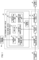
- FIG. 1 is a diagram showing a configuration of a fluid pressure supply device 30 including a fluid control device 10 and a valve module 20 according to an embodiment.
- the fluid control device 10 serves to control the valve module 20.
- a fluid for example, air
- the fluid that has flowed into the inflow port of the valve module 20 passes through the valve module, and flows out from an outflow port of the valve module 20.
- the fluid that has flowed out from the outflow port of the valve module 20 passes through a piping, and is supplied to an external device 42.
- the valve module 20 includes a pressure adjusting valve 50, a flow rate meter 52, and a disconnection valve 54.
- the pressure adjusting valve 50 is capable of adjusting the pressure of the fluid supplied from the fluid supply source 40.
- the pressure adjusting valve 50 is a proportional control valve that adjusts the pressure of the fluid in response to an electrical signal.
- the pressure adjusting valve 50 includes a main valve, and a pilot valve that adjusts a degree of opening of the main valve.
- the fluid supplied from the fluid supply source 40 flows into an inlet port of the pressure adjusting valve 50.
- the inlet port of the pressure adjusting valve 50 communicates with the inflow port of the aforementioned valve module 20.
- the inlet port of the pressure adjusting valve 50 may also serve as the inflow port of the aforementioned valve module 20.
- the pressure of the fluid that has flowed into the inlet port of the pressure adjusting valve 50 is adjusted in accordance with the degree of opening of the main valve.
- the fluid whose pressure has been adjusted flows out of an outlet port of the pressure adjusting valve 50.
- the fluid output from the pressure adjusting valve 50 is directed toward the disconnection valve 54.
- the flow rate meter 52 measures a flow rate F of the fluid through the valve module 20.
- the flow rate meter 52 measures the flow rate F of the fluid that is output from the pressure adjusting valve 50 and flows toward the disconnection valve 54.
- the disconnection valve 54 includes a main valve, and a pilot valve that opens and closes the main valve.
- the disconnection valve 54 by closing the main valve, disconnects the supply of the fluid output from the pressure adjusting valve 50 to the external device 42.
- the fluid output from the pressure adjusting valve 50 flows into an inlet port of a disconnection valve 54.
- the main valve of the disconnection valve 54 is open, the fluid that has entered into the inlet port of the disconnection valve 54 flows out from the outlet port of the disconnection valve 54.
- the outlet port of the disconnection valve 54 communicates with the outflow port of the aforementioned valve module 20.
- the fluid that has flowed out from the outlet port of the disconnection valve 54 is directed toward the external device 42. In this manner, the supply of the fluid output from the pressure adjusting valve 50 to the external device 42 is realized.
- the outlet port of the disconnection valve 54 may serve as the outflow port of the aforementioned valve module 20.
- the fluid that has entered into the inlet port of the disconnection valve 54 does not flow out of the outlet port of the disconnection valve 54. More specifically, when the main valve of the disconnection valve 54 is closed, the supply of the fluid output from the pressure adjusting valve 50 to the external device 42 is disconnected.
- the fluid control device 10 includes a processing circuit 60 and a storage device 62.
- the processing circuit 60 includes a processor such as a CPU or a GPU or the like.
- the storage device 62 includes a volatile memory such as a RAM or the like, and a nonvolatile memory such as a ROM or a flash memory or the like.
- the volatile memory is used as a working memory of the processor.
- the nonvolatile memory stores programs to be executed by the processor and other necessary data.
- the processing circuit 60 includes an interface unit 70, a timer unit 72, a flow rate determination unit 74, a pressure adjusting valve control unit 76, a flow rate acquisition unit 78, and a disconnection valve control unit 80.
- the processing circuit 60 executes a program that is stored in the storage device 62, the interface unit 70, the timer unit 72, the flow rate determination unit 74, the pressure adjusting valve control unit 76, the flow rate acquisition unit 78, and the disconnection valve control unit 80 are realized.
- At least a portion from among the interface unit 70, the timer unit 72, the flow rate determination unit 74, the pressure adjusting valve control unit 76, the flow rate acquisition unit 78, and the disconnection valve control unit 80 may be realized by an integrated circuit such as an ASIC or an FPGA or the like, or alternatively, by an electronic circuit including a discrete device.
- the interface unit 70 performs two-way communications with an operator terminal 90 via wireless communications.
- the interface unit 70 may also perform two-way communications with the operator terminal 90 by way of wired communications.
- the interface unit 70 acquires instructions of the operator from the operator terminal 90.
- the interface unit 70 may acquire the instructions of the operator from an operating device such as a non-illustrated button or slide switch that is provided on the fluid pressure supply device 30.
- the operator terminal 90 for example, is a PC (Personal Computer) or a PLC (Programmable Logic Controller).
- the timer unit 72 includes a clock circuit or a timer circuit, and measures time. Based on time information from the clock circuit or the timer circuit, the timer unit 72 measures a first predetermined time period TM1 and a second predetermined time period TM2, which will be discussed later.
- the flow rate acquisition unit 78 acquires from the flow rate meter 52 the flow rate F measured by the flow rate meter 52. For example, the flow rate F of the fluid may decrease due to the external device 42 being stopped.
- the flow rate determination unit 74 determines whether or not the flow rate F acquired by the flow rate acquisition unit 78 is less than or equal to a threshold value FT continuously for at least the first predetermined time period TM1.
- the pressure adjusting valve control unit 76 controls the pressure adjusting valve 50 using an electrical signal.
- the pilot valve of the pressure adjusting valve 50 operates in response to the electrical signal output from the pressure adjusting valve control unit 76.
- the degree of opening of the main valve of the pressure adjusting valve 50 is adjusted to various levels. In the case that the degree of opening of the main valve is zero, the pressure adjusting valve 50 is in a closed state.
- the disconnection valve control unit 80 controls the disconnection valve 54 using an electrical signal.
- the pilot valve of the disconnection valve 54 operates in response to the electrical signal output from the disconnection valve control unit 80. By the pilot valve of the disconnection valve 54 being operated, the main valve of the disconnection valve 54 is opened and closed.
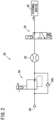
- FIG. 2 is a circuit diagram of the valve module 20 in an operation mode and a standby mode.
- the pressure adjusting valve control unit 76 controls the pressure adjusting valve 50, and thereby adjusts to a first pressure P1 the pressure of the fluid supplied from the fluid supply source 40.
- a mode in which the fluid is output at the first pressure P1 from the pressure adjusting valve 50 is referred to as the operation mode.
- the main valve of the disconnection valve 54 is open.
- the fluid that is output at the first pressure P1 from the pressure adjusting valve 50 flows out of the valve module 20, and is supplied to the external device 42.
- the pressure adjusting valve control unit 76 controls the pressure adjusting valve 50 in a manner so that the fluid is output from the pressure adjusting valve 50 at a second pressure P2 which is lower than the first pressure P1. Stated otherwise, in the case that the flow rate F of the fluid is less than or equal to the threshold value FT for at least the first predetermined time period TM1, and further, the instruction C1 has been issued by the operator, the pressure adjusting valve control unit 76 controls the pressure adjusting valve 50, and thereby causes the fluid to be output at the second pressure P2 from the pressure adjusting valve 50. A mode in which the fluid is output at the second pressure P2 from the pressure adjusting valve 50 is referred to as the standby mode. More specifically, the pressure adjusting valve control unit 76 switches the operation mode to the standby mode.
- the standby mode there is a possibility that the external device 42 may be stopped, a necessity to supply the fluid at the first pressure P1 may be low, and the fluid at a second pressure P2, which is lower than the first pressure P1, is output from the pressure adjusting valve 50.
- the pressure adjusting valve control unit 76 instructs the pilot valve of the pressure adjusting valve 50 to cause the degree of opening of the main valve of the pressure adjusting valve 50 to be reduced, in a manner so that the pressure P decreases from the first pressure P1 to the second pressure P2.
- the main valve of the disconnection valve 54 is maintained open.
- the standby mode in a state in which a pressure P of the fluid has been adjusted to the second pressure P2, the fluid is supplied to the external device 42.
- needless consumption of the fluid is reduced as compared with the operation mode.
- FIG. 3 is a circuit diagram of the valve module 20 in an isolation mode.
- the disconnection valve control unit 80 controls the disconnection valve 54, in a manner so that the supply of the fluid output from the pressure adjusting valve 50 to the external device 42 is disconnected. Specifically, the disconnection valve control unit 80 causes the pilot valve of the disconnection valve 54 to close the main valve of the disconnection valve 54. A mode in which the supply of the fluid to the external device 42 is disconnected is referred to as the isolation mode. More specifically, the disconnection valve control unit 80 switches the standby mode to the isolation mode.
- the disconnection valve control unit 80 together with causing the disconnection of the supply of the fluid to the external device 42, opens the outlet port of the disconnection valve 54 to the atmosphere. Stated otherwise, the outflow port of the valve module 20 is open to the atmosphere.
- the pressure adjusting valve control unit 76 preferably causes the pilot valve of the pressure adjusting valve 50 to set the degree of opening of the main valve of the pressure adjusting valve 50 to zero. More specifically, it is preferable that the pressure adjusting valve control unit 76 closes the main valve of the pressure adjusting valve 50.
- the pressure adjusting valve 50 includes a check valve 50c.
- the check valve 50c allows fluid that flows out from the outlet port to flow from the outlet port of the pressure adjusting valve 50 and towards the inlet port. Accordingly, for example, in the case that the fluid pressure supply device 30 is stopped in order to perform maintenance and inspection of the valve module 20, the safety of the inspection operator can be ensured.
- valve module 20 may be placed in a normally closed state.
- the main valve of the disconnection valve 54 similar to the state shown in FIG. 3 , becomes placed in a closed state. In this case, the fluid in the interior of the valve module 20 is discharged, and the safety of the inspection operator can be ensured.
- valve module 20 may also be placed in a normally open state.
- the main valve of the pressure adjusting valve 50 and the main valve of the disconnection valve 54 both become placed in the open state. In this case, the supply of the fluid to the external device 42 can be continued.
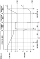
- FIG. 4 is a time chart illustrating a change in the flow rate F and the pressure P of the fluid that is supplied to the external device 42.
- FIG. 4 an aspect by which the flow rate F of the fluid supplied to the external device 42 changes is as shown in FIG. 4 .
- an aspect by which the pressure P of the fluid supplied to the external device 42 changes is as shown in FIG. 4 .
- the valve module 20 is operating in the operation mode.
- the fluid which is of a first flow rate F1 is supplied at the first pressure P1 to the external device 42. Thereafter, when the external device 42 stops consuming the fluid due to a stoppage of the external device 42, the flow rate F of the fluid begins to decrease.
- the time at which the flow rate F of the fluid has started to decrease is defined as a time T1.
- the flow rate F of the fluid reaches the threshold value FT.
- the time at which the flow rate F of the fluid has reached the threshold value FT is defined as a time T3.
- the interface unit 70 acquires an instruction C1 from the operator.
- the time at which the interface unit 70 has acquired the instruction C1 is defined as a time T2 which is later than the time T1 and earlier than the time T3.
- the timer unit 72 starts measuring time.
- a Time T4 is defined as a time at which the first predetermined time period TM1 has elapsed from when the timer unit 72 starts measuring time at time T3. Further, it is assumed that, at time T4, permission to transition to the standby mode has not been canceled by the operator (transitioning to the standby mode has not been prohibited). In this case, at time T4, the flow rate determination unit 74 determines that the flow rate F is less than or equal to the threshold value FT continuously for at least the first predetermined time period TM1. The step in which such a determination step is carried out is referred to as a flow rate determination step. At time T4, the pressure adjusting valve control unit 76 switches the operation mode to the standby mode.
- the pressure adjusting valve control unit 76 controls the pressure adjusting valve 50 to thereby close the main valve of the pressure adjusting valve 50.
- the flow rate F of the fluid becomes zero.
- the timer unit 72 starts measuring time again.
- the main valve of the pressure adjusting valve 50 is temporarily maintained in a state of being closed. During that period, the fluid is gradually consumed downstream from the valve module 20. For example, in the case that the fluid is air, the air is consumed by air purging or the like in the piping connecting the outflow port of the valve module 20 and the external device 42.
- the pressure P of the fluid gradually decreases. The time at which the pressure P of the fluid decreases from the first pressure P1 to the second pressure P2 is defined as a time T5.
- the pressure adjusting valve control unit 76 controls the pressure adjusting valve 50, in a manner so that the fluid is output at the second pressure P2 from the pressure adjusting valve 50.
- the step in which such a control process is carried out is referred to as a first pressure adjusting valve control step.
- the fluid flow rate F begins to increase.
- the pressure P of the fluid remains at the second pressure P2.
- the time at which the flow rate F of the fluid reaches a second flow rate F2 is defined as a time T6. From time T6 and thereafter, the fluid of the second flow rate F2 is supplied at the second pressure P2 to the external device 42.
- the timer unit 72 begins measuring time at time T4, and then the second predetermined time period TM2 elapses.
- the time at which the second predetermined time period TM2 has elapsed is referred to as a time T7.
- the disconnection valve control unit 80 switches the standby mode to the isolation mode.
- the pressure adjusting valve control unit 76 controls the pressure adjusting valve 50 to thereby close the main valve of the pressure adjusting valve 50.
- the disconnection valve control unit 80 controls the disconnection valve 54, and thereby closes the main valve of the disconnection valve 54.
- the step in which such a control process is carried out is referred to as a first disconnection valve control step.
- the supply of the fluid output from the pressure adjusting valve 50 to the external device 42 is disconnected.
- control of the pressure adjusting valve 50 may be carried out by the pressure adjusting valve control unit 76 after the control of the disconnection valve 54 has been carried out by the disconnection valve control unit 80.
- the flow rate F of the fluid becomes zero.
- the disconnection valve control unit 80 causes the outlet port of the disconnection valve 54 (the outflow port of the valve module 20) to be opened to the atmosphere.
- the pressure of the outflow port of the valve module 20 decreases to a pressure which is equal to the atmospheric pressure PA.
- the time at which the interface unit 70 has acquired an instruction C2 from the operator is defined as a time T8.
- the instruction C2 indicates that an instruction has been issued from the operator to return to the operation mode.
- the pressure adjusting valve control unit 76 switches the isolation mode to the operation mode.
- the pressure adjusting valve control unit 76 controls the pressure adjusting valve 50, and thereby causes the pressure P of the fluid output from the pressure adjusting valve 50 to gradually increase from the atmospheric pressure PA to the first pressure P1 at a rate of increase determined in accordance with time.
- the soft start function prevents the pressure P of the fluid output from the pressure adjusting valve 50 from suddenly increasing from the atmospheric pressure PA to the first pressure P1.
- the step in which such a control process is carried out is referred to as a second pressure adjusting valve control step.
- the disconnection valve control unit 80 controls the disconnection valve 54, and thereby causes the fluid output from the pressure adjusting valve 50 to be supplied to the external device 42.
- the step in which such a control process is carried out is referred to as a second disconnection valve control step. From time T8 to time T9, the flow rate F and the pressure P of the fluid gradually increase. From time T9 and thereafter, the fluid of the first flow rate F1 is supplied at the first pressure P1 to the external device 42.
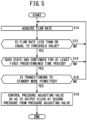
- FIG. 5 is a flowchart showing a procedure of a fluid control process performed by the fluid control device 10 in the case that the operation mode is switched to the standby mode.
- the present processing procedure is carried out by the processing circuit 60 of the fluid control device 10 executing the program that is stored in the storage device 62.
- the valve module 20 is operating in the operation mode.
- the fluid which is of the first flow rate F1 is supplied at the first pressure P1 to the external device 42.
- step S10 the flow rate acquisition unit 78 acquires from the flow rate meter 52 the flow rate F measured by the flow rate meter 52.
- the step in which the process of step S10 is carried out is referred to as a flow rate acquisition step.
- step S12 the flow rate determination unit 74 determines whether or not the flow rate F acquired by the flow rate acquisition unit 78 is less than or equal to the threshold value FT. In the case it has become YES in step S12, the present processing procedure proceeds to step S14. In the case it has become NO in step S12, the present processing procedure returns to step S10.
- step S14 the flow rate determination unit 74 determines whether or not the flow rate F is less than or equal to the threshold value FT continuously for at least the first predetermined time period TM1 that was measured by the timer unit 72. In the case it has become YES in step S14, the present processing procedure proceeds to step S16. In the case it has become NO in step S14, the present processing procedure returns to step S10.
- the step in which the processes of step S12 and step S14 are carried out corresponds to the aforementioned flow rate determination step.
- step S16 the pressure adjusting valve control unit 76 determines whether or not the interface unit 70 has acquired the instruction C1 from the operator.
- the instruction C1 indicates that the standby mode has been permitted by the operator.
- step S18 the present processing procedure proceeds to step S18.
- step S16 then transitioning to the standby mode is prohibited. In this case, permission to transition to the standby mode has not been given from the operator, or alternatively, permission to transition to the standby mode has been canceled by the operator.
- the present processing procedure returns to step S10.
- step S18 the pressure adjusting valve control unit 76 controls the pressure adjusting valve 50, in a manner so that the fluid is output at the second pressure P2 from the pressure adjusting valve 50.
- the step in which the process of step S18 is carried out corresponds to the aforementioned first pressure adjusting valve control step.
- the present processing procedure comes to an end.
- the valve module 20 operates in the standby mode.
- FIG. 6 is a flowchart showing a processing procedure of a fluid control process performed by the fluid control device 10 in the case that the standby mode is switched to the operation mode or the isolation mode.
- the present processing procedure is carried out by the processing circuit 60 of the fluid control device 10 executing the program that is stored in the storage device 62.
- the valve module 20 is operating in the standby mode.
- the fluid which is of the second flow rate F2 is supplied at the second pressure P2 to the external device 42.
- the timer unit 72 starts measuring the second predetermined time period TM2.
- step S32 the pressure adjusting valve control unit 76 determines whether or not the interface unit 70 has acquired an instruction C3 from the operator.
- the instruction C3 indicates that transitioning to the standby mode is prohibited.
- the instruction C3 corresponds to a cancellation of the permission to transition to the standby mode from the operator that was made in step S16 of FIG. 5 .
- the present processing procedure proceeds to step S34.
- the present processing procedure proceeds to step S40.
- step S34 the pressure adjusting valve control unit 76 controls the pressure adjusting valve 50, and thereby causes the pressure P of the fluid output from the pressure adjusting valve 50 to increase from the second pressure P2 to the first pressure P1 according to a rate of increase determined in accordance with time.
- step S36 the pressure adjusting valve control unit 76 controls the pressure adjusting valve 50, in a manner so that the fluid is output at the first pressure P1 from the pressure adjusting valve 50.
- the present processing procedure comes to an end.
- the valve module 20 operates in the operation mode.
- step S40 the timer unit 72 determines whether or not the second predetermined time period TM2 has elapsed. In the case it has become YES in step S40, the present processing procedure proceeds to step S42. In the case it has become NO in step S40, the present processing procedure returns to step S32.
- step S42 the pressure adjusting valve control unit 76 controls the pressure adjusting valve 50 to thereby close the pressure adjusting valve 50.
- step S44 the disconnection valve control unit 80 controls the disconnection valve 54, and thereby closes the main valve of the disconnection valve 54.
- the supply of the fluid output from the pressure adjusting valve 50 to the external device 42 is disconnected.
- the step in which the process of step S44 is carried out corresponds to the aforementioned first disconnection valve control step.
- the outflow port of the valve module 20 is open to the atmosphere, and therefore, becomes a pressure which is equal to the atmospheric pressure PA.
- the present processing procedure comes to an end.
- the valve module 20 operates in the isolation mode.
- FIG. 7 is a flowchart showing a processing procedure of a fluid control process performed by the fluid control device 10 in the case that the isolation mode is switched to the operation mode.
- the present processing procedure is carried out by the processing circuit 60 of the fluid control device 10 executing the program that is stored in the storage device 62.
- the valve module 20 is operating in the isolation mode. In the isolation mode, the supply of the fluid output from the pressure adjusting valve 50 to the external device 42 is disconnected. The pressure at the outflow port of the valve module 20 is equal to the atmospheric pressure PA.
- step S60 the disconnection valve control unit 80 determines whether or not the interface unit 70 has acquired the instruction C2 from the operator.
- the instruction C2 indicates that an instruction has been issued from the operator to return to the operation mode.
- step S62 the present processing procedure repeats step S60.
- step S62 the disconnection valve control unit 80 controls the disconnection valve 54, and thereby opens the disconnection valve 54.
- the pressure adjusting valve 50 opens in a subsequent process, the fluid output from the pressure adjusting valve 50 is supplied to the external device 42.
- the step in which the process of step S62 is carried out corresponds to the aforementioned second disconnection valve control step.
- step S64 the pressure adjusting valve control unit 76 controls the pressure adjusting valve 50, and thereby causes the pressure P of the fluid output from the pressure adjusting valve 50 to be increased from the atmospheric pressure PA to the first pressure P1 at a rate of increase determined in accordance with time.
- step S66 the pressure adjusting valve control unit 76 controls the pressure adjusting valve 50, in a manner so that the fluid is output at the first pressure P1 from the pressure adjusting valve 50.
- the step in which the processes of step S64 and step S66 are carried out corresponds to the aforementioned second pressure adjusting valve control step. When the process of step S66 is completed, the present processing procedure comes to an end.
- the valve module 20 operates in the operation mode.
- the pressure adjusting valve 50 of the valve module 20 is a proportional control valve that adjusts the pressure of the fluid in response to an electrical signal.
- the valve module 20A controlled by the fluid control device 10 according to Exemplary Modification 1 includes a pressure adjusting valve 50A that outputs fluid at two types of pressure in response to electrical signals corresponding to ON and OFF, the flow rate meter 52, a throttle valve 100, a switching valve 102, and the disconnection valve 54.
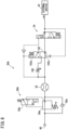
- FIG. 8 is a circuit diagram of the valve module 20A in the operation mode.
- the throttle valve 100 and the switching valve 102 are disposed between the pressure adjusting valve 50A and the disconnection valve 54.
- the pressure adjusting valve 50A includes a main valve 50m, and a pilot valve 50p that adjusts a degree of opening of the main valve 50m.
- the fluid supplied at the first pressure P1 from the fluid supply source 40 flows into an inlet port of the pressure adjusting valve 50A.
- the pressure adjusting valve 50A in the case that the electrical signal output from the pressure adjusting valve control unit 76 of the fluid control device 10 to the pilot valve 50p of the pressure adjusting valve 50A is OFF, the pressure adjusting valve 50A outputs the fluid while substantially maintaining the first pressure P1 of the fluid supplied from the fluid supply source 40. In the case that the electrical signal output from the pressure adjusting valve control unit 76 to the pilot valve 50p of the pressure adjusting valve 50A is ON, the pressure adjusting valve 50A adjusts the first pressure P1 of the fluid supplied from the fluid supply source 40 to the second pressure P2, and outputs the fluid.
- the electrical signal output from the pressure adjusting valve control unit 76 to the pilot valve 50p of the pressure adjusting valve 50A is OFF.
- the pressure adjusting valve 50A outputs the fluid at the first pressure P1.
- the disconnection valve control unit 80 controls the disconnection valve 54, and thereby opens the main valve of the disconnection valve 54.
- the first pressure P1 of the fluid output from the pressure adjusting valve 50A presses a first pressure receiving surface 102a of the switching valve 102.
- a first pressing force S1 of the first pressure P1 with respect to the first pressure receiving surface 102a acts in a direction to press down the position of the switching valve 102.
- the first pressure P1 of the fluid that flows out from the outlet port of the disconnection valve 54 to the external device 42 presses against a second pressure receiving surface 102b of the switching valve 102.
- a second pressing force S2 of the first pressure P1 with respect to the second pressure receiving surface 102b acts in a direction to press up the position of the switching valve 102.
- the area of the first pressure receiving surface 102a of the switching valve 102 is smaller than the area of the second pressure receiving surface 102b.
- the first pressing force S1 applied to the first pressure receiving surface 102a is smaller than the second pressing force S2 applied to the second pressure receiving surface 102b. Accordingly, as shown in FIG. 8 , the position of the switching valve 102 is pressed up.
- the switching valve 102 causes the fluid output from the pressure adjusting valve 50A to flow, but not via the throttle valve 100, to the disconnection valve 54. In this manner, in the operation mode, the fluid at the first pressure P1 that is output from the pressure adjusting valve 50A is supplied to the external device 42.
- FIG. 9 is a circuit diagram of the valve module 20A in the standby mode.
- the electrical signal output from the pressure adjusting valve control unit 76 to the pilot valve 50p of the pressure adjusting valve 50A is ON.
- the pressure adjusting valve 50A outputs the fluid at the second pressure P2.
- the main valve of the disconnection valve 54 remains open.
- a third pressing force S3 of the second pressure P2 with respect to the first pressure receiving surface 102a is smaller than a fourth pressing force S4 of the second pressure P2 with respect to the second pressure receiving surface 102b.
- the position of the switching valve 102 is pressed up.
- the switching valve 102 causes the fluid output from the pressure adjusting valve 50A to flow, but not via the throttle valve 100, to the disconnection valve 54. In this manner, in the standby mode, the fluid at the second pressure P2 that is output from the pressure adjusting valve 50A is supplied to the external device 42.
- FIG. 10 is a circuit diagram of the valve module 20A in the isolation mode.
- the electrical signal output from the pressure adjusting valve control unit 76 to the pilot valve 50p of the pressure adjusting valve 50A is OFF.
- the pressure adjusting valve 50A outputs the fluid at the first pressure P1.
- the pressure adjusting valve 50A may also output the fluid at the second pressure P2.
- the disconnection valve control unit 80 controls the disconnection valve 54, and thereby closes the main valve of the disconnection valve 54.
- the disconnection valve control unit 80 opens the outlet port of the disconnection valve 54 to the atmosphere.
- the pressure at the outlet port of the disconnection valve 54 is equal to the atmospheric pressure PA.
- a fifth pressing force S5 of the second pressure P2 with respect to the first pressure receiving surface 102a is larger than a sixth pressing force S6 of the atmospheric pressure PA with respect to the second pressure receiving surface 102b. In such a case, as shown in FIG. 10 , the position of the switching valve 102 is pressed down.
- the disconnection valve control unit 80 controls the disconnection valve 54, and thereby opens the main valve of the disconnection valve 54.
- the pressure adjusting valve 50A outputs the fluid at the first pressure P1.
- the switching valve 102 causes the fluid output from the pressure adjusting valve 50A to flow via the throttle valve 100 to the disconnection valve 54.
- the pressure at the outlet port of the disconnection valve 54 gradually rises.
- the switching valve 102 causes the fluid output from the pressure adjusting valve 50A to flow, but not via the throttle valve 100, to the disconnection valve 54. In this manner, a so-called soft start function is realized.
- the switching valve 102 either causes the fluid that is output from the pressure adjusting valve 50A to flow via the throttle valve 100 to the disconnection valve 54, or alternatively, causes the fluid to flow, but not via the throttle valve 100, to the disconnection valve 54.
- FIG. 11 is a flowchart showing a processing procedure of a fluid control process performed by the fluid control device 10 in the case that the standby mode is switched to the operation mode or the isolation mode.
- the present processing procedure is carried out by the processing circuit 60 of the fluid control device 10 executing the program that is stored in the storage device 62.
- FIG. 12 is a flowchart showing a procedure of a fluid control process performed by the fluid control device 10 in the case that the isolation mode is switched to the operation mode.
- the present processing procedure is carried out by the processing circuit 60 of the fluid control device 10 executing the program that is stored in the storage device 62.
- the reference characters applied to the steps of the present processing procedure shown in FIG. 12 correspond to a part of the reference characters applied to the steps of the processing procedure shown in FIG. 7 .
- the flowchart shown in FIG. 12 does not include step S64 shown in FIG. 7 . Accordingly, when the process of step S62 is completed, the process of step S66 is carried out.
- the standby mode is switched to the isolation mode.
- the standby mode is maintained.
- FIG. 13 is a flowchart for describing a procedure of a fluid control process performed by the fluid control device 10 in the case that there was an instruction C4 to prohibit a transition to the isolation mode.
- the present processing procedure is carried out by the processing circuit 60 of the fluid control device 10 executing the program that is stored in the storage device 62.
- a portion of the reference characters applied to the steps of the present processing procedure shown in FIG. 13 coincide with the reference characters applied to the steps of the processing procedure shown in FIG. 6 .
- the steps whose reference characters coincide with each other the same processing is executed, and therefore, descriptions of the processing in those steps will be omitted herein.
- step S80 the pressure adjusting valve control unit 76 determines whether or not the interface unit 70 has acquired the instruction C4 from the operator.
- the instruction C4 indicates that transitioning to the isolation mode is prohibited.
- step S80 the present processing procedure comes to an end. Accordingly, even if the second predetermined time period TM2 has elapsed during the standby mode, the standby mode is maintained. In the case it has become NO in step S80, the present processing procedure proceeds to step S42.
- the isolation mode is switched to the standby mode.
- FIG. 14 is a flowchart for describing a procedure of a fluid control process performed by the fluid control device 10 in the case that the isolation mode is switched to the standby mode.
- the present processing procedure is carried out by the processing circuit 60 of the fluid control device 10 executing the program that is stored in the storage device 62.
- a portion of the reference characters applied to the steps of the present processing procedure shown in FIG. 14 coincide with the reference characters applied to the steps of the processing procedure shown in FIG. 7 .
- the steps whose reference characters coincide with each other the same processing is executed, and therefore, descriptions of the processing in those steps will be omitted herein.
- step S90 step S92, step S94, and step S96 are added thereto.
- the present processing procedure proceeds to step S90.
- step S90 the pressure disconnection valve control unit 80 determines whether or not the interface unit 70 has acquired an instruction C5 from the operator.
- the instruction C5 indicates that an instruction has been issued from the operator to return to the standby mode.
- step S92 the present processing procedure proceeds to step S92.
- step S90 the present processing procedure returns to step S60.
- step S92 the disconnection valve control unit 80 controls the disconnection valve 54, and thereby opens the disconnection valve 54.
- the pressure adjusting valve 50 opens in a subsequent process, the fluid output from the pressure adjusting valve 50 is supplied to the external device 42.
- step S94 the pressure adjusting valve control unit 76 controls the pressure adjusting valve 50, and thereby causes the pressure P of the fluid output from the pressure adjusting valve 50 to be increased from the atmospheric pressure PA to the second pressure P2 at a rate of increase determined in accordance with time.
- step S96 the pressure adjusting valve control unit 76 controls the pressure adjusting valve 50, in a manner so that the fluid is output at the second pressure P2 from the pressure adjusting valve 50.
- the operation mode in the case it is determined that the flow rate F acquired during the operation mode is less than or equal to the threshold value FT continuously for at least the first predetermined time period TM1, and further, that the standby mode has been permitted by the operator, the operation mode is switched to the standby mode.
- the operation mode in the case that transitioning to the standby mode has been prohibited beforehand by the operator, the operation mode is maintained.
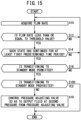
- FIG. 15 is a flowchart for describing a procedure of a fluid control process performed by the fluid control device 10 in the case that there was an instruction C3 to prohibit a transition to the standby mode.
- the present processing procedure is carried out by the processing circuit 60 of the fluid control device 10 executing the program that is stored in the storage device 62.
- a portion of the reference characters applied to the steps of the present processing procedure shown in FIG. 15 coincide with the reference characters applied to the steps of the processing procedure shown in FIG. 5 .
- the steps whose reference characters coincide with each other the same processing is executed, and therefore, descriptions of the processing in those steps will be omitted herein.
- step S100 the pressure adjusting valve control unit 76 determines whether or not the interface unit 70 has acquired the instruction C3 from the operator.
- the instruction C3 indicates that transitioning to the standby mode is prohibited.
- step S100 In the case that the instruction C3 has been acquired beforehand in the operation mode, the answer becomes YES in step S100. In the case it has become YES in step S100, the present processing procedure comes to an end.
- the valve module 20 operates in the operation mode. In the case it has become NO in step S100, the present processing procedure proceeds to step S18.
- the pressure adjusting valve 50 is a proportional control valve that adjusts the pressure of the fluid in response to an electrical signal.
- the pilot valve of the pressure adjusting valve 50 operates in response to the electrical signal output by the pressure adjusting valve control unit 76.
- the pressure adjusting valve control unit 76 that causes the pilot valve of the pressure adjusting valve 50 to be operated may be installed integrally together with a housing of the pressure adjusting valve 50. More specifically, the pressure adjusting valve control unit 76 and the pressure adjusting valve 50 may be an integrated module MR.
- the disconnection valve control unit 80 and the disconnection valve 54 may be an integrated module MS.
- the interface unit 70, the timer unit 72, the flow rate determination unit 74, the flow rate acquisition unit 78, and the flow rate meter 52 may be integrated together into a module MM.
- Each of the modules MR, MS, and MM is capable of being replaced.
- the module MR that is old but is currently in use can be replaced with a new module MR.
- the module MS that is old but is currently in use can be replaced with a new module MS.
- the module MM that is old but is currently in use can be replaced with a new module MM .
- the pilot valve 50p of the pressure adjusting valve 50A operates in response to an electrical signal corresponding to ON and OFF.
- the pressure adjusting valve control unit 76 that operates the pilot valve 50p of the pressure adjusting valve 50A may be mounted integrally together with a housing of the main valve 50m and the pilot valve 50p of the pressure adjusting valve 50A. More specifically, the pressure adjusting valve control unit 76 and the pressure adjusting valve 50A may be an integrated module MP.
- the disconnection valve control unit 80, the disconnection valve 54, the throttle valve 100, and the switching valve 102 may be integrated together into a module MG.
- the interface unit 70, the timer unit 72, the flow rate determination unit 74, the flow rate acquisition unit 78, and the flow rate meter 52 may be integrated together into a module MM .
- Each of the modules MP, MG, and MM is capable of being replaced.
- the module MP that is old but is currently in use can be replaced with a new module MP.
- the module MG that is old but is currently in use can be replaced with a new module MG.
- the module MM that is old but is currently in use can be replaced with a new module MM .
- the flow rate meter 52 in addition to the flow rate F of the fluid passing through the valve module 20, may also measure the temperature and the pressure of the fluid.
- the flow rate acquisition unit 78 acquires from the flow rate meter 52 the flow rate F, the temperature, and the pressure measured by the flow rate meter 52.
- the flow rate acquisition unit 78 by performing a calculation using the flow rate F acquired from the flow rate meter 52, is capable of acquiring a cumulative flow rate.
- the interface unit 70 issues a notification to the operator terminal 90 of information in relation to the flow rate F of the fluid, the cumulative flow rate, the temperature, and the pressure, as well as other information.
- the other information that is notified to the operator from the interface unit 70 includes information on an operating state of the valve module 20, and information on a body size of the fluid pressure supply device 30.
- the processing circuit of the operator terminal 90 by executing a program that is stored in a storage device of the operator terminal 90, outputs to the display device of the operator terminal 90 information that is notified from the fluid control device 10.
- the processing circuit of the operator terminal 90 by executing the program that is stored in the storage device of the operator terminal 90, outputs to the display device of the operator terminal 90 a proposal screen for proposing a new fluid pressure supply device 30 with a body size that is compatible with the information notified from the fluid control device 10.
Landscapes
- Engineering & Computer Science (AREA)
- Physics & Mathematics (AREA)
- Fluid Mechanics (AREA)
- Mechanical Engineering (AREA)
- General Engineering & Computer Science (AREA)
- General Physics & Mathematics (AREA)
- Automation & Control Theory (AREA)
- Chemical & Material Sciences (AREA)
- Analytical Chemistry (AREA)
- Control Of Fluid Pressure (AREA)
Abstract
Description
- The present invention relates to a fluid control device, a fluid pressure supply apparatus (device), and a fluid control method.
- In
US 2019/257329 A1 , a fluid control device is disclosed that shifts to a hold mode when a flow rate of air in a working mode becomes less than or equal to a threshold value. In the hold mode, the air is provided to an external fluid device at a lower pressure than in the working mode. - In accordance with the fluid control device disclosed in
US 2019/257329 A1 , the fluid is supplied even in the case that the supply of the fluid to the external device is unnecessary. Accordingly, a problem arises in that the fluid is consumed unnecessarily. - The present invention has the object of solving the aforementioned problem.
- A first aspect of the present invention is characterized by a fluid control device configured to control a valve module equipped with a pressure adjusting valve configured to be capable of adjusting a pressure of a fluid supplied from a fluid supply source, and a disconnection valve configured to be capable of disconnecting a supply of the fluid output from the pressure adjusting valve to an external device, the fluid control device comprising a flow rate acquisition unit configured to acquire from a flow rate meter a flow rate of the fluid passing through the valve module, a flow rate determination unit configured to determine whether or not the flow rate that was acquired is less than or equal to a threshold value continuously at least for a first predetermined time period, a pressure adjusting valve control unit which is configured, in the case that it is determined that the flow rate acquired during an operation mode in which the fluid is output at a first pressure from the pressure adjusting valve is continuously less than or equal to the threshold value for at least the first predetermined time period, and a standby mode from an operator is permitted, to control the pressure adjusting valve in a manner so that the fluid is output from the pressure adjusting valve at a second pressure which is lower than the first pressure, and to switch the operation mode to the standby mode, and a disconnection valve control unit which is configured, in the case that a second predetermined time period has elapsed during the standby mode, to control the disconnection valve in a manner so that the supply of the fluid output from the pressure adjusting valve to the external device is disconnected, and to switch the standby mode to an isolation mode.
- A second aspect of the present invention is characterized by a fluid pressure supply device comprising the fluid control device according to the first aspect, and the valve module.
- A third aspect of the present invention is characterized by a fluid control method of controlling a valve module equipped with a pressure adjusting valve configured to be capable of adjusting a pressure of a fluid supplied from a fluid supply source, and a disconnection valve configured to be capable of disconnecting a supply of the fluid output from the pressure adjusting valve to an external device, the fluid control method comprising a flow rate acquisition step of acquiring from a flow rate meter a flow rate of the fluid passing through the valve module, a flow rate determination step of determining whether or not the flow rate that was acquired is less than or equal to a threshold value continuously for at least a first predetermined time period, a first pressure adjusting valve controlling step in which, in the case that it is determined that the flow rate acquired during an operation mode in which the fluid is output at a first pressure from the pressure adjusting valve is continuously less than or equal to the threshold value for at least the first predetermined time period, and a standby mode from an operator is permitted, the pressure adjusting valve is controlled at a second pressure which is lower than the first pressure, and the operation mode is switched to the standby mode, and a first disconnection valve controlling step in which, in the case that a second predetermined time period has elapsed during the standby mode, the disconnection valve is controlled in a manner so that the supply of the fluid output from the pressure adjusting valve to the external device is disconnected, and the standby mode is switched to an isolation mode.
- According to the present invention, an amount of the fluid supplied to the external device can be reduced.
-
- [
FIG. 1] FIG. 1 is a diagram showing a configuration of a fluid pressure supply device including a fluid control device and a valve module according to an embodiment; - [
FIG. 2] FIG. 2 is a circuit diagram of the valve module in an operation mode and a standby mode; - [
FIG. 3] FIG. 3 is a circuit diagram of the valve module in an isolation mode; - [
FIG. 4] FIG. 4 is a time chart illustrating changes in a flow rate and a pressure of the fluid that is supplied to an external device; - [
FIG. 5] FIG. 5 is a flowchart showing a processing procedure of a fluid control process performed by the fluid control device in the case that the operation mode is switched to the standby mode; - [
FIG. 6] FIG. 6 is a flowchart showing a processing procedure of a fluid control process performed by the fluid control device in the case that the standby mode is switched to the operation mode or the isolation mode; - [
FIG. 7] FIG. 7 is a flowchart showing a processing procedure of a fluid control process performed by the fluid control device in the case that the isolation mode is switched to the operation mode; - [
FIG. 8] FIG. 8 is a circuit diagram of the valve module in the operation mode; - [
FIG. 9] FIG. 9 is a circuit diagram of the valve module in the standby mode; - [
FIG. 10] FIG. 10 is a circuit diagram of the valve module in the isolation mode; - [
FIG. 11] FIG. 11 is a flowchart showing a processing procedure of a fluid control process performed by the fluid control device in the case that the standby mode is switched to the operation mode or the isolation mode; - [
FIG. 12] FIG. 12 is a flowchart showing a processing procedure of a fluid control process performed by the fluid control device in the case that the isolation mode is switched to the operation mode; - [
FIG. 13] FIG. 13 is a flowchart for describing a processing procedure of a fluid control process performed by the fluid control device in the case that there was an instruction to prohibit a transition to the isolation mode; - [
FIG. 14] FIG. 14 is a flowchart for describing a processing procedure of a fluid control process performed by the fluid control device in the case that the isolation mode is switched to the standby mode; and - [
FIG. 15] FIG. 15 is a flowchart for describing a processing procedure of a fluid control process performed by the fluid control device in the case that there was an instruction to prohibit a transition to the standby mode. -
FIG. 1 is a diagram showing a configuration of a fluidpressure supply device 30 including afluid control device 10 and avalve module 20 according to an embodiment. Thefluid control device 10 serves to control thevalve module 20. A fluid (for example, air) that is supplied from afluid supply source 40 passes through a piping and flows into an inflow port of thevalve module 20. The fluid that has flowed into the inflow port of thevalve module 20 passes through the valve module, and flows out from an outflow port of thevalve module 20. The fluid that has flowed out from the outflow port of thevalve module 20 passes through a piping, and is supplied to anexternal device 42. Thevalve module 20 includes apressure adjusting valve 50, aflow rate meter 52, and adisconnection valve 54. - The
pressure adjusting valve 50 is capable of adjusting the pressure of the fluid supplied from thefluid supply source 40. In the present embodiment, thepressure adjusting valve 50 is a proportional control valve that adjusts the pressure of the fluid in response to an electrical signal. Thepressure adjusting valve 50 includes a main valve, and a pilot valve that adjusts a degree of opening of the main valve. The fluid supplied from thefluid supply source 40 flows into an inlet port of thepressure adjusting valve 50. The inlet port of thepressure adjusting valve 50 communicates with the inflow port of theaforementioned valve module 20. Moreover, it should be noted that the inlet port of thepressure adjusting valve 50 may also serve as the inflow port of theaforementioned valve module 20. - The pressure of the fluid that has flowed into the inlet port of the
pressure adjusting valve 50 is adjusted in accordance with the degree of opening of the main valve. The fluid whose pressure has been adjusted flows out of an outlet port of thepressure adjusting valve 50. The fluid output from thepressure adjusting valve 50 is directed toward thedisconnection valve 54. - The
flow rate meter 52 measures a flow rate F of the fluid through thevalve module 20. In the present embodiment, theflow rate meter 52 measures the flow rate F of the fluid that is output from thepressure adjusting valve 50 and flows toward thedisconnection valve 54. - At a time at which the
disconnection valve 54 is open, the fluid output from thepressure adjusting valve 50 is supplied to theexternal device 42. Thedisconnection valve 54 includes a main valve, and a pilot valve that opens and closes the main valve. Thedisconnection valve 54, by closing the main valve, disconnects the supply of the fluid output from thepressure adjusting valve 50 to theexternal device 42. - The fluid output from the
pressure adjusting valve 50 flows into an inlet port of adisconnection valve 54. In the case that the main valve of thedisconnection valve 54 is open, the fluid that has entered into the inlet port of thedisconnection valve 54 flows out from the outlet port of thedisconnection valve 54. The outlet port of thedisconnection valve 54 communicates with the outflow port of theaforementioned valve module 20. The fluid that has flowed out from the outlet port of thedisconnection valve 54 is directed toward theexternal device 42. In this manner, the supply of the fluid output from thepressure adjusting valve 50 to theexternal device 42 is realized. Moreover, it should be noted that the outlet port of thedisconnection valve 54 may serve as the outflow port of theaforementioned valve module 20. - In the case that the main valve of the
disconnection valve 54 is closed, the fluid that has entered into the inlet port of thedisconnection valve 54 does not flow out of the outlet port of thedisconnection valve 54. More specifically, when the main valve of thedisconnection valve 54 is closed, the supply of the fluid output from thepressure adjusting valve 50 to theexternal device 42 is disconnected. - The
fluid control device 10 includes aprocessing circuit 60 and astorage device 62. Theprocessing circuit 60 includes a processor such as a CPU or a GPU or the like. Thestorage device 62 includes a volatile memory such as a RAM or the like, and a nonvolatile memory such as a ROM or a flash memory or the like. The volatile memory is used as a working memory of the processor. The nonvolatile memory stores programs to be executed by the processor and other necessary data. - The
processing circuit 60 includes aninterface unit 70, atimer unit 72, a flowrate determination unit 74, a pressure adjustingvalve control unit 76, a flowrate acquisition unit 78, and a disconnectionvalve control unit 80. By theprocessing circuit 60 executing a program that is stored in thestorage device 62, theinterface unit 70, thetimer unit 72, the flowrate determination unit 74, the pressure adjustingvalve control unit 76, the flowrate acquisition unit 78, and the disconnectionvalve control unit 80 are realized. At least a portion from among theinterface unit 70, thetimer unit 72, the flowrate determination unit 74, the pressure adjustingvalve control unit 76, the flowrate acquisition unit 78, and the disconnectionvalve control unit 80 may be realized by an integrated circuit such as an ASIC or an FPGA or the like, or alternatively, by an electronic circuit including a discrete device. - The
interface unit 70 performs two-way communications with anoperator terminal 90 via wireless communications. Theinterface unit 70 may also perform two-way communications with theoperator terminal 90 by way of wired communications. Theinterface unit 70 acquires instructions of the operator from theoperator terminal 90. Theinterface unit 70 may acquire the instructions of the operator from an operating device such as a non-illustrated button or slide switch that is provided on the fluidpressure supply device 30. Theoperator terminal 90, for example, is a PC (Personal Computer) or a PLC (Programmable Logic Controller). - The
timer unit 72 includes a clock circuit or a timer circuit, and measures time. Based on time information from the clock circuit or the timer circuit, thetimer unit 72 measures a first predetermined time period TM1 and a second predetermined time period TM2, which will be discussed later. - The flow
rate acquisition unit 78 acquires from theflow rate meter 52 the flow rate F measured by theflow rate meter 52. For example, the flow rate F of the fluid may decrease due to theexternal device 42 being stopped. The flowrate determination unit 74 determines whether or not the flow rate F acquired by the flowrate acquisition unit 78 is less than or equal to a threshold value FT continuously for at least the first predetermined time period TM1. - The pressure adjusting
valve control unit 76 controls thepressure adjusting valve 50 using an electrical signal. The pilot valve of thepressure adjusting valve 50 operates in response to the electrical signal output from the pressure adjustingvalve control unit 76. By the pilot valve of thepressure adjusting valve 50 being operated, the degree of opening of the main valve of thepressure adjusting valve 50 is adjusted to various levels. In the case that the degree of opening of the main valve is zero, thepressure adjusting valve 50 is in a closed state. - The disconnection
valve control unit 80 controls thedisconnection valve 54 using an electrical signal. The pilot valve of thedisconnection valve 54 operates in response to the electrical signal output from the disconnectionvalve control unit 80. By the pilot valve of thedisconnection valve 54 being operated, the main valve of thedisconnection valve 54 is opened and closed. -
FIG. 2 is a circuit diagram of thevalve module 20 in an operation mode and a standby mode. In order to use the fluid in theexternal device 42, the pressure adjustingvalve control unit 76 controls thepressure adjusting valve 50, and thereby adjusts to a first pressure P1 the pressure of the fluid supplied from thefluid supply source 40. A mode in which the fluid is output at the first pressure P1 from thepressure adjusting valve 50 is referred to as the operation mode. - In the operation mode, the main valve of the
disconnection valve 54 is open. In the operation mode, the fluid that is output at the first pressure P1 from thepressure adjusting valve 50 flows out of thevalve module 20, and is supplied to theexternal device 42. - It is assumed that, during the operation mode, an instruction C1 indicating that the standby mode has been permitted by the operator is acquired by the
interface unit 70. Furthermore, during the operation mode, it is determined by the flowrate determination unit 74 that the flow rate F of the fluid measured by theflow rate meter 52 remains less than or equal to the threshold value FT for at least the first predetermined time period TM1. - In this case, the pressure adjusting
valve control unit 76 controls thepressure adjusting valve 50 in a manner so that the fluid is output from thepressure adjusting valve 50 at a second pressure P2 which is lower than the first pressure P1. Stated otherwise, in the case that the flow rate F of the fluid is less than or equal to the threshold value FT for at least the first predetermined time period TM1, and further, the instruction C1 has been issued by the operator, the pressure adjustingvalve control unit 76 controls thepressure adjusting valve 50, and thereby causes the fluid to be output at the second pressure P2 from thepressure adjusting valve 50. A mode in which the fluid is output at the second pressure P2 from thepressure adjusting valve 50 is referred to as the standby mode. More specifically, the pressure adjustingvalve control unit 76 switches the operation mode to the standby mode. - In the standby mode, there is a possibility that the
external device 42 may be stopped, a necessity to supply the fluid at the first pressure P1 may be low, and the fluid at a second pressure P2, which is lower than the first pressure P1, is output from thepressure adjusting valve 50. The pressure adjustingvalve control unit 76 instructs the pilot valve of thepressure adjusting valve 50 to cause the degree of opening of the main valve of thepressure adjusting valve 50 to be reduced, in a manner so that the pressure P decreases from the first pressure P1 to the second pressure P2. The main valve of thedisconnection valve 54 is maintained open. In the standby mode, in a state in which a pressure P of the fluid has been adjusted to the second pressure P2, the fluid is supplied to theexternal device 42. In the standby mode, needless consumption of the fluid is reduced as compared with the operation mode. -
FIG. 3 is a circuit diagram of thevalve module 20 in an isolation mode. In the case that the second predetermined time period TM2 has elapsed during the standby mode, the disconnectionvalve control unit 80 controls thedisconnection valve 54, in a manner so that the supply of the fluid output from thepressure adjusting valve 50 to theexternal device 42 is disconnected. Specifically, the disconnectionvalve control unit 80 causes the pilot valve of thedisconnection valve 54 to close the main valve of thedisconnection valve 54. A mode in which the supply of the fluid to theexternal device 42 is disconnected is referred to as the isolation mode. More specifically, the disconnectionvalve control unit 80 switches the standby mode to the isolation mode. - In the isolation mode, the disconnection
valve control unit 80, together with causing the disconnection of the supply of the fluid to theexternal device 42, opens the outlet port of thedisconnection valve 54 to the atmosphere. Stated otherwise, the outflow port of thevalve module 20 is open to the atmosphere. - In the isolation mode, the pressure adjusting
valve control unit 76 preferably causes the pilot valve of thepressure adjusting valve 50 to set the degree of opening of the main valve of thepressure adjusting valve 50 to zero. More specifically, it is preferable that the pressure adjustingvalve control unit 76 closes the main valve of thepressure adjusting valve 50. - In addition, the
pressure adjusting valve 50 includes acheck valve 50c. In any one of the operation mode, the standby mode, and the isolation mode, in the case that the fluidpressure supply device 30 is stopped, the supply of the fluid from thefluid supply source 40 is disconnected. When the inlet port of thepressure adjusting valve 50 has become an atmospheric pressure PA, thecheck valve 50c allows fluid that flows out from the outlet port to flow from the outlet port of thepressure adjusting valve 50 and towards the inlet port. Accordingly, for example, in the case that the fluidpressure supply device 30 is stopped in order to perform maintenance and inspection of thevalve module 20, the safety of the inspection operator can be ensured. - Further, in the case that the supply of electrical power to the fluid
pressure supply device 30 is suddenly stopped, thevalve module 20 may be placed in a normally closed state. When thevalve module 20 is placed in the normally closed state, the main valve of thedisconnection valve 54, similar to the state shown inFIG. 3 , becomes placed in a closed state. In this case, the fluid in the interior of thevalve module 20 is discharged, and the safety of the inspection operator can be ensured. - Further, in the case that the supply of electrical power to the fluid
pressure supply device 30 is suddenly stopped, thevalve module 20 may also be placed in a normally open state. In the state in which thevalve module 20 is in a normally open state, similar to the state shown inFIG. 2 , the main valve of thepressure adjusting valve 50 and the main valve of thedisconnection valve 54 both become placed in the open state. In this case, the supply of the fluid to theexternal device 42 can be continued. -
FIG. 4 is a time chart illustrating a change in the flow rate F and the pressure P of the fluid that is supplied to theexternal device 42. As the time progresses from time T0 to time T9 and thereafter, an aspect by which the flow rate F of the fluid supplied to theexternal device 42 changes is as shown inFIG. 4 . Furthermore, as the time progresses from time T0 to time T9 and thereafter, an aspect by which the pressure P of the fluid supplied to theexternal device 42 changes is as shown inFIG. 4 . - At time T0 in the example shown in
FIG. 4 , thevalve module 20 is operating in the operation mode. At time T0, the fluid which is of a first flow rate F1 is supplied at the first pressure P1 to theexternal device 42. Thereafter, when theexternal device 42 stops consuming the fluid due to a stoppage of theexternal device 42, the flow rate F of the fluid begins to decrease. The time at which the flow rate F of the fluid has started to decrease is defined as a time T1. Thereafter, the flow rate F of the fluid reaches the threshold value FT. The time at which the flow rate F of the fluid has reached the threshold value FT is defined as a time T3. - Moreover, at a time prior to the time T3, the
interface unit 70 acquires an instruction C1 from the operator. For example, the time at which theinterface unit 70 has acquired the instruction C1 is defined as a time T2 which is later than the time T1 and earlier than the time T3. From the time T3 at which the flow rate F has reached the threshold value FT, thetimer unit 72 starts measuring time. - In the example shown in
FIG. 4 , even after the time T3, the flow rate F is less than or equal to the threshold value FT. A Time T4 is defined as a time at which the first predetermined time period TM1 has elapsed from when thetimer unit 72 starts measuring time at time T3. Further, it is assumed that, at time T4, permission to transition to the standby mode has not been canceled by the operator (transitioning to the standby mode has not been prohibited). In this case, at time T4, the flowrate determination unit 74 determines that the flow rate F is less than or equal to the threshold value FT continuously for at least the first predetermined time period TM1. The step in which such a determination step is carried out is referred to as a flow rate determination step. At time T4, the pressure adjustingvalve control unit 76 switches the operation mode to the standby mode. - The
valve module 20, which has been operated in the operation mode up until time T4, operates in the standby mode from time T4 until time T7. At time T4, the pressure adjustingvalve control unit 76 controls thepressure adjusting valve 50 to thereby close the main valve of thepressure adjusting valve 50. At time T4, the flow rate F of the fluid becomes zero. At time T4, thetimer unit 72 starts measuring time again. - From time T4 until time T5, the main valve of the
pressure adjusting valve 50 is temporarily maintained in a state of being closed. During that period, the fluid is gradually consumed downstream from thevalve module 20. For example, in the case that the fluid is air, the air is consumed by air purging or the like in the piping connecting the outflow port of thevalve module 20 and theexternal device 42. Along therewith, as shown inFIG. 4 , from time T4, the pressure P of the fluid gradually decreases. The time at which the pressure P of the fluid decreases from the first pressure P1 to the second pressure P2 is defined as a time T5. - At time T5, the pressure adjusting
valve control unit 76 controls thepressure adjusting valve 50, in a manner so that the fluid is output at the second pressure P2 from thepressure adjusting valve 50. The step in which such a control process is carried out is referred to as a first pressure adjusting valve control step. - At time T5, the fluid flow rate F begins to increase. The pressure P of the fluid remains at the second pressure P2. The time at which the flow rate F of the fluid reaches a second flow rate F2 is defined as a time T6. From time T6 and thereafter, the fluid of the second flow rate F2 is supplied at the second pressure P2 to the
external device 42. - In the standby mode, the
timer unit 72 begins measuring time at time T4, and then the second predetermined time period TM2 elapses. The time at which the second predetermined time period TM2 has elapsed is referred to as a time T7. At time T7, the disconnectionvalve control unit 80 switches the standby mode to the isolation mode. Thevalve module 20, which has been operated in the standby mode from time T4 until time T7, operates in the isolation mode from time T7 and thereafter. - At time T7, the pressure adjusting
valve control unit 76 controls thepressure adjusting valve 50 to thereby close the main valve of thepressure adjusting valve 50. At time T7, the disconnectionvalve control unit 80 controls thedisconnection valve 54, and thereby closes the main valve of thedisconnection valve 54. The step in which such a control process is carried out is referred to as a first disconnection valve control step. In accordance with this feature, the supply of the fluid output from thepressure adjusting valve 50 to theexternal device 42 is disconnected. - Moreover, the control of the
pressure adjusting valve 50 may be carried out by the pressure adjustingvalve control unit 76 after the control of thedisconnection valve 54 has been carried out by the disconnectionvalve control unit 80. At time T7, the flow rate F of the fluid becomes zero. At time T7, the disconnectionvalve control unit 80 causes the outlet port of the disconnection valve 54 (the outflow port of the valve module 20) to be opened to the atmosphere. At time T7, the pressure of the outflow port of thevalve module 20 decreases to a pressure which is equal to the atmospheric pressure PA. - In the isolation mode, the time at which the
interface unit 70 has acquired an instruction C2 from the operator is defined as a time T8. The instruction C2 indicates that an instruction has been issued from the operator to return to the operation mode. At time T8, the pressure adjustingvalve control unit 76 switches the isolation mode to the operation mode. - The
valve module 20, which has been operated in the isolation mode from time T7 until time T8, operates in the operation mode from time T8 and thereafter. From time T8 to time T9, the pressure adjustingvalve control unit 76 controls thepressure adjusting valve 50, and thereby causes the pressure P of the fluid output from thepressure adjusting valve 50 to gradually increase from the atmospheric pressure PA to the first pressure P1 at a rate of increase determined in accordance with time. In this manner, a so-called soft start function is realized. The soft start function prevents the pressure P of the fluid output from thepressure adjusting valve 50 from suddenly increasing from the atmospheric pressure PA to the first pressure P1. The step in which such a control process is carried out is referred to as a second pressure adjusting valve control step. - At time T8, the disconnection
valve control unit 80 controls thedisconnection valve 54, and thereby causes the fluid output from thepressure adjusting valve 50 to be supplied to theexternal device 42. The step in which such a control process is carried out is referred to as a second disconnection valve control step. From time T8 to time T9, the flow rate F and the pressure P of the fluid gradually increase. From time T9 and thereafter, the fluid of the first flow rate F1 is supplied at the first pressure P1 to theexternal device 42. -
FIG. 5 is a flowchart showing a procedure of a fluid control process performed by thefluid control device 10 in the case that the operation mode is switched to the standby mode. The present processing procedure is carried out by theprocessing circuit 60 of thefluid control device 10 executing the program that is stored in thestorage device 62. When the present processing procedure begins, thevalve module 20 is operating in the operation mode. In the operation mode, the fluid which is of the first flow rate F1 is supplied at the first pressure P1 to theexternal device 42. - When the present processing procedure is started, in step S10, the flow
rate acquisition unit 78 acquires from theflow rate meter 52 the flow rate F measured by theflow rate meter 52. The step in which the process of step S10 is carried out is referred to as a flow rate acquisition step. - In step S12, the flow
rate determination unit 74 determines whether or not the flow rate F acquired by the flowrate acquisition unit 78 is less than or equal to the threshold value FT. In the case it has become YES in step S12, the present processing procedure proceeds to step S14. In the case it has become NO in step S12, the present processing procedure returns to step S10. - In step S14, the flow
rate determination unit 74 determines whether or not the flow rate F is less than or equal to the threshold value FT continuously for at least the first predetermined time period TM1 that was measured by thetimer unit 72. In the case it has become YES in step S14, the present processing procedure proceeds to step S16. In the case it has become NO in step S14, the present processing procedure returns to step S10. The step in which the processes of step S12 and step S14 are carried out corresponds to the aforementioned flow rate determination step. - In step S16, the pressure adjusting
valve control unit 76 determines whether or not theinterface unit 70 has acquired the instruction C1 from the operator. The instruction C1 indicates that the standby mode has been permitted by the operator. In the case it has become YES in step S16, the present processing procedure proceeds to step S18. In the case it has become NO in step S16, then transitioning to the standby mode is prohibited. In this case, permission to transition to the standby mode has not been given from the operator, or alternatively, permission to transition to the standby mode has been canceled by the operator. In the case it has become NO in step S16, the present processing procedure returns to step S10. - In step S18, the pressure adjusting
valve control unit 76 controls thepressure adjusting valve 50, in a manner so that the fluid is output at the second pressure P2 from thepressure adjusting valve 50. The step in which the process of step S18 is carried out corresponds to the aforementioned first pressure adjusting valve control step. When the process of step S18 is completed, the present processing procedure comes to an end. Thevalve module 20 operates in the standby mode. -
FIG. 6 is a flowchart showing a processing procedure of a fluid control process performed by thefluid control device 10 in the case that the standby mode is switched to the operation mode or the isolation mode. The present processing procedure is carried out by theprocessing circuit 60 of thefluid control device 10 executing the program that is stored in thestorage device 62. When the present processing procedure begins, thevalve module 20 is operating in the standby mode. In the standby mode, the fluid which is of the second flow rate F2 is supplied at the second pressure P2 to theexternal device 42. When the present processing procedure is started, in step S30, thetimer unit 72 starts measuring the second predetermined time period TM2. - In step S32, the pressure adjusting
valve control unit 76 determines whether or not theinterface unit 70 has acquired an instruction C3 from the operator. The instruction C3 indicates that transitioning to the standby mode is prohibited. In the case that the instruction C3 is acquired in the standby mode, the instruction C3 corresponds to a cancellation of the permission to transition to the standby mode from the operator that was made in step S16 ofFIG. 5 . In the case it has become YES in step S32, the present processing procedure proceeds to step S34. In the case it has become NO in step S32, the present processing procedure proceeds to step S40. - In the case it has become YES in step S32, then in step S34, the pressure adjusting
valve control unit 76 controls thepressure adjusting valve 50, and thereby causes the pressure P of the fluid output from thepressure adjusting valve 50 to increase from the second pressure P2 to the first pressure P1 according to a rate of increase determined in accordance with time. - In step S36, the pressure adjusting
valve control unit 76 controls thepressure adjusting valve 50, in a manner so that the fluid is output at the first pressure P1 from thepressure adjusting valve 50. When the process of step S36 is completed, the present processing procedure comes to an end. Thevalve module 20 operates in the operation mode. - In the case it has become NO in step S32, then in step S40, the
timer unit 72 determines whether or not the second predetermined time period TM2 has elapsed. In the case it has become YES in step S40, the present processing procedure proceeds to step S42. In the case it has become NO in step S40, the present processing procedure returns to step S32. - In step S42, the pressure adjusting
valve control unit 76 controls thepressure adjusting valve 50 to thereby close thepressure adjusting valve 50. - In step S44, the disconnection
valve control unit 80 controls thedisconnection valve 54, and thereby closes the main valve of thedisconnection valve 54. In accordance with this feature, the supply of the fluid output from thepressure adjusting valve 50 to theexternal device 42 is disconnected. The step in which the process of step S44 is carried out corresponds to the aforementioned first disconnection valve control step. The outflow port of thevalve module 20 is open to the atmosphere, and therefore, becomes a pressure which is equal to the atmospheric pressure PA. When the process of step S44 is completed, the present processing procedure comes to an end. Thevalve module 20 operates in the isolation mode. -
FIG. 7 is a flowchart showing a processing procedure of a fluid control process performed by thefluid control device 10 in the case that the isolation mode is switched to the operation mode. The present processing procedure is carried out by theprocessing circuit 60 of thefluid control device 10 executing the program that is stored in thestorage device 62. When the present processing procedure begins, thevalve module 20 is operating in the isolation mode. In the isolation mode, the supply of the fluid output from thepressure adjusting valve 50 to theexternal device 42 is disconnected. The pressure at the outflow port of thevalve module 20 is equal to the atmospheric pressure PA. - When the present processing procedure is started, in step S60, the disconnection
valve control unit 80 determines whether or not theinterface unit 70 has acquired the instruction C2 from the operator. The instruction C2 indicates that an instruction has been issued from the operator to return to the operation mode. In the case it has become YES in step S60, the present processing procedure proceeds to step S62. In the case it has become NO in step S60, the present processing procedure repeats step S60. - In step S62, the disconnection
valve control unit 80 controls thedisconnection valve 54, and thereby opens thedisconnection valve 54. When thepressure adjusting valve 50 opens in a subsequent process, the fluid output from thepressure adjusting valve 50 is supplied to theexternal device 42. The step in which the process of step S62 is carried out corresponds to the aforementioned second disconnection valve control step. - In step S64, the pressure adjusting
valve control unit 76 controls thepressure adjusting valve 50, and thereby causes the pressure P of the fluid output from thepressure adjusting valve 50 to be increased from the atmospheric pressure PA to the first pressure P1 at a rate of increase determined in accordance with time. In step S66, the pressure adjustingvalve control unit 76 controls thepressure adjusting valve 50, in a manner so that the fluid is output at the first pressure P1 from thepressure adjusting valve 50. The step in which the processes of step S64 and step S66 are carried out corresponds to the aforementioned second pressure adjusting valve control step. When the process of step S66 is completed, the present processing procedure comes to an end. Thevalve module 20 operates in the operation mode. - The above-described embodiment may be modified in the following manner.
- In the above-described embodiment, the
pressure adjusting valve 50 of thevalve module 20 is a proportional control valve that adjusts the pressure of the fluid in response to an electrical signal. Thevalve module 20A controlled by thefluid control device 10 according to Exemplary Modification 1 includes apressure adjusting valve 50A that outputs fluid at two types of pressure in response to electrical signals corresponding to ON and OFF, theflow rate meter 52, athrottle valve 100, a switchingvalve 102, and thedisconnection valve 54. -
FIG. 8 is a circuit diagram of thevalve module 20A in the operation mode. Thethrottle valve 100 and the switchingvalve 102 are disposed between thepressure adjusting valve 50A and thedisconnection valve 54. Thepressure adjusting valve 50A includes amain valve 50m, and apilot valve 50p that adjusts a degree of opening of themain valve 50m. The fluid supplied at the first pressure P1 from thefluid supply source 40 flows into an inlet port of thepressure adjusting valve 50A. - In the present exemplary modification, in the case that the electrical signal output from the pressure adjusting
valve control unit 76 of thefluid control device 10 to thepilot valve 50p of thepressure adjusting valve 50A is OFF, thepressure adjusting valve 50A outputs the fluid while substantially maintaining the first pressure P1 of the fluid supplied from thefluid supply source 40. In the case that the electrical signal output from the pressure adjustingvalve control unit 76 to thepilot valve 50p of thepressure adjusting valve 50A is ON, thepressure adjusting valve 50A adjusts the first pressure P1 of the fluid supplied from thefluid supply source 40 to the second pressure P2, and outputs the fluid. - As shown in
FIG. 8 , in the case that thevalve module 20A operates in the operation mode, the electrical signal output from the pressure adjustingvalve control unit 76 to thepilot valve 50p of thepressure adjusting valve 50A is OFF. Thepressure adjusting valve 50A outputs the fluid at the first pressure P1. The disconnectionvalve control unit 80 controls thedisconnection valve 54, and thereby opens the main valve of thedisconnection valve 54. - The first pressure P1 of the fluid output from the
pressure adjusting valve 50A presses a firstpressure receiving surface 102a of the switchingvalve 102. A first pressing force S1 of the first pressure P1 with respect to the firstpressure receiving surface 102a acts in a direction to press down the position of the switchingvalve 102. The first pressure P1 of the fluid that flows out from the outlet port of thedisconnection valve 54 to theexternal device 42 presses against a secondpressure receiving surface 102b of the switchingvalve 102. A second pressing force S2 of the first pressure P1 with respect to the secondpressure receiving surface 102b acts in a direction to press up the position of the switchingvalve 102. - The area of the first
pressure receiving surface 102a of the switchingvalve 102 is smaller than the area of the secondpressure receiving surface 102b. In such a case, the first pressing force S1 applied to the firstpressure receiving surface 102a is smaller than the second pressing force S2 applied to the secondpressure receiving surface 102b. Accordingly, as shown inFIG. 8 , the position of the switchingvalve 102 is pressed up. The switchingvalve 102 causes the fluid output from thepressure adjusting valve 50A to flow, but not via thethrottle valve 100, to thedisconnection valve 54. In this manner, in the operation mode, the fluid at the first pressure P1 that is output from thepressure adjusting valve 50A is supplied to theexternal device 42. -
FIG. 9 is a circuit diagram of thevalve module 20A in the standby mode. In the case that thevalve module 20A operates in the standby mode, the electrical signal output from the pressure adjustingvalve control unit 76 to thepilot valve 50p of thepressure adjusting valve 50A is ON. Thepressure adjusting valve 50A outputs the fluid at the second pressure P2. The main valve of thedisconnection valve 54 remains open. - A third pressing force S3 of the second pressure P2 with respect to the first
pressure receiving surface 102a is smaller than a fourth pressing force S4 of the second pressure P2 with respect to the secondpressure receiving surface 102b. In such a case, as shown inFIG. 9 , the position of the switchingvalve 102 is pressed up. The switchingvalve 102 causes the fluid output from thepressure adjusting valve 50A to flow, but not via thethrottle valve 100, to thedisconnection valve 54. In this manner, in the standby mode, the fluid at the second pressure P2 that is output from thepressure adjusting valve 50A is supplied to theexternal device 42. -
FIG. 10 is a circuit diagram of thevalve module 20A in the isolation mode. In the case that thevalve module 20A operates in the isolation mode, the electrical signal output from the pressure adjustingvalve control unit 76 to thepilot valve 50p of thepressure adjusting valve 50A is OFF. Thepressure adjusting valve 50A outputs the fluid at the first pressure P1. Moreover, thepressure adjusting valve 50A may also output the fluid at the second pressure P2. The disconnectionvalve control unit 80 controls thedisconnection valve 54, and thereby closes the main valve of thedisconnection valve 54. The disconnectionvalve control unit 80 opens the outlet port of thedisconnection valve 54 to the atmosphere. - The pressure at the outlet port of the
disconnection valve 54 is equal to the atmospheric pressure PA. A fifth pressing force S5 of the second pressure P2 with respect to the firstpressure receiving surface 102a is larger than a sixth pressing force S6 of the atmospheric pressure PA with respect to the secondpressure receiving surface 102b. In such a case, as shown inFIG. 10 , the position of the switchingvalve 102 is pressed down. - When the isolation mode is switched to the operation mode, the disconnection
valve control unit 80 controls thedisconnection valve 54, and thereby opens the main valve of thedisconnection valve 54. Thepressure adjusting valve 50A outputs the fluid at the first pressure P1. The switchingvalve 102 causes the fluid output from thepressure adjusting valve 50A to flow via thethrottle valve 100 to thedisconnection valve 54. The pressure at the outlet port of thedisconnection valve 54 gradually rises. - Along therewith, when the pressing force of the pressure at the outlet port of the
disconnection valve 54 with respect to the secondpressure receiving surface 102b becomes greater than the first pressing force S1 of the first pressure P1 with respect to the firstpressure receiving surface 102a, the position of the switchingvalve 102 is pushed up. In this case, as shown inFIG. 8 , the switchingvalve 102 causes the fluid output from thepressure adjusting valve 50A to flow, but not via thethrottle valve 100, to thedisconnection valve 54. In this manner, a so-called soft start function is realized. Depending on the pressure of the fluid that flows out from thedisconnection valve 54 to theexternal device 42, the switchingvalve 102 either causes the fluid that is output from thepressure adjusting valve 50A to flow via thethrottle valve 100 to thedisconnection valve 54, or alternatively, causes the fluid to flow, but not via thethrottle valve 100, to thedisconnection valve 54. - In the present exemplary modification, in the case that the operation mode is switched to the standby mode, the flowchart showing the processing procedure of the fluid control process performed by the
fluid control device 10 coincides with the flowchart shown inFIG. 5 . Therefore, a description of the processing procedure will be omitted herein. -
FIG. 11 is a flowchart showing a processing procedure of a fluid control process performed by thefluid control device 10 in the case that the standby mode is switched to the operation mode or the isolation mode. The present processing procedure is carried out by theprocessing circuit 60 of thefluid control device 10 executing the program that is stored in thestorage device 62. - The reference characters applied to the steps of the present processing procedure shown in
FIG. 11 correspond to a part of the reference characters applied to the steps of the processing procedure shown inFIG. 6 . In the steps whose reference characters coincide with each other, the same processing is executed, and therefore, descriptions of the processing in each of those steps shown inFIG. 11 will be omitted herein. The flowchart shown inFIG. 11 does not include step S34 and step S42 shown inFIG. 6 . Accordingly, when the process of step S32 is completed, the process of step S36 is carried out. In the case it has become YES in step S40, the present processing procedure proceeds to step S44. -
FIG. 12 is a flowchart showing a procedure of a fluid control process performed by thefluid control device 10 in the case that the isolation mode is switched to the operation mode. The present processing procedure is carried out by theprocessing circuit 60 of thefluid control device 10 executing the program that is stored in thestorage device 62. - The reference characters applied to the steps of the present processing procedure shown in
FIG. 12 correspond to a part of the reference characters applied to the steps of the processing procedure shown inFIG. 7 . In the steps whose reference characters coincide with each other, the same processing is executed, and therefore, descriptions of the processing in each of those steps shown inFIG. 12 will be omitted herein. The flowchart shown inFIG. 12 does not include step S64 shown inFIG. 7 . Accordingly, when the process of step S62 is completed, the process of step S66 is carried out. - In the above-described embodiment, when the second predetermined time period TM2 elapses during the standby mode, the standby mode is switched to the isolation mode. In the
fluid control device 10 according to the Exemplary Modification 2, in the case that transitioning to the isolation mode has been prohibited by the operator, even if the second predetermined time period TM2 period has elapsed during the standby mode, the standby mode is maintained. -
FIG. 13 is a flowchart for describing a procedure of a fluid control process performed by thefluid control device 10 in the case that there was an instruction C4 to prohibit a transition to the isolation mode. The present processing procedure is carried out by theprocessing circuit 60 of thefluid control device 10 executing the program that is stored in thestorage device 62. A portion of the reference characters applied to the steps of the present processing procedure shown inFIG. 13 coincide with the reference characters applied to the steps of the processing procedure shown inFIG. 6 . In the steps whose reference characters coincide with each other, the same processing is executed, and therefore, descriptions of the processing in those steps will be omitted herein. - In
FIG. 13 , differently fromFIG. 6 , the process of step S80 is added thereto. In the case it has become YES in step S40, the present processing procedure proceeds to step S80. In step S80, the pressure adjustingvalve control unit 76 determines whether or not theinterface unit 70 has acquired the instruction C4 from the operator. The instruction C4 indicates that transitioning to the isolation mode is prohibited. - In the case it has become YES in step S80, the present processing procedure comes to an end. Accordingly, even if the second predetermined time period TM2 has elapsed during the standby mode, the standby mode is maintained. In the case it has become NO in step S80, the present processing procedure proceeds to step S42.
- In the
fluid control device 10 according to Exemplary Modification 3, in the case that an instruction is issued from the operator to return to the standby mode, the isolation mode is switched to the standby mode. -
FIG. 14 is a flowchart for describing a procedure of a fluid control process performed by thefluid control device 10 in the case that the isolation mode is switched to the standby mode. The present processing procedure is carried out by theprocessing circuit 60 of thefluid control device 10 executing the program that is stored in thestorage device 62. A portion of the reference characters applied to the steps of the present processing procedure shown inFIG. 14 coincide with the reference characters applied to the steps of the processing procedure shown inFIG. 7 . In the steps whose reference characters coincide with each other, the same processing is executed, and therefore, descriptions of the processing in those steps will be omitted herein. - In
FIG. 14 , differently fromFIG. 7 , step S90, step S92, step S94, and step S96 are added thereto. In the case it has become NO in step S60, the present processing procedure proceeds to step S90. In step S90, the pressure disconnectionvalve control unit 80 determines whether or not theinterface unit 70 has acquired an instruction C5 from the operator. The instruction C5 indicates that an instruction has been issued from the operator to return to the standby mode. In the case it has become YES in step S90, the present processing procedure proceeds to step S92. In the case it has become NO in step S90, the present processing procedure returns to step S60. - In step S92, the disconnection
valve control unit 80 controls thedisconnection valve 54, and thereby opens thedisconnection valve 54. When thepressure adjusting valve 50 opens in a subsequent process, the fluid output from thepressure adjusting valve 50 is supplied to theexternal device 42. - In step S94, the pressure adjusting
valve control unit 76 controls thepressure adjusting valve 50, and thereby causes the pressure P of the fluid output from thepressure adjusting valve 50 to be increased from the atmospheric pressure PA to the second pressure P2 at a rate of increase determined in accordance with time. In step S96, the pressure adjustingvalve control unit 76 controls thepressure adjusting valve 50, in a manner so that the fluid is output at the second pressure P2 from thepressure adjusting valve 50. When the process of step S96 is completed, the present processing procedure comes to an end. Thevalve module 20 operates in the standby mode. - In the above-described embodiment, in the case it is determined that the flow rate F acquired during the operation mode is less than or equal to the threshold value FT continuously for at least the first predetermined time period TM1, and further, that the standby mode has been permitted by the operator, the operation mode is switched to the standby mode. In the
fluid control device 10 according to the Exemplary Modification 4, in the case that transitioning to the standby mode has been prohibited beforehand by the operator, the operation mode is maintained. -
FIG. 15 is a flowchart for describing a procedure of a fluid control process performed by thefluid control device 10 in the case that there was an instruction C3 to prohibit a transition to the standby mode. The present processing procedure is carried out by theprocessing circuit 60 of thefluid control device 10 executing the program that is stored in thestorage device 62. A portion of the reference characters applied to the steps of the present processing procedure shown inFIG. 15 coincide with the reference characters applied to the steps of the processing procedure shown inFIG. 5 . In the steps whose reference characters coincide with each other, the same processing is executed, and therefore, descriptions of the processing in those steps will be omitted herein. - In
FIG. 15 , differently fromFIG. 5 , the process of step S100 is added thereto. In the case it has become YES in step S16, the present processing procedure proceeds to step S100. In step S100, the pressure adjustingvalve control unit 76 determines whether or not theinterface unit 70 has acquired the instruction C3 from the operator. The instruction C3 indicates that transitioning to the standby mode is prohibited. - In the case that the instruction C3 has been acquired beforehand in the operation mode, the answer becomes YES in step S100. In the case it has become YES in step S100, the present processing procedure comes to an end. The
valve module 20 operates in the operation mode. In the case it has become NO in step S100, the present processing procedure proceeds to step S18. - In the above-described embodiment, the
pressure adjusting valve 50 is a proportional control valve that adjusts the pressure of the fluid in response to an electrical signal. The pilot valve of thepressure adjusting valve 50 operates in response to the electrical signal output by the pressure adjustingvalve control unit 76. Having done so, the pressure adjustingvalve control unit 76 that causes the pilot valve of thepressure adjusting valve 50 to be operated may be installed integrally together with a housing of thepressure adjusting valve 50. More specifically, the pressure adjustingvalve control unit 76 and thepressure adjusting valve 50 may be an integrated module MR. - Similarly, the disconnection
valve control unit 80 and thedisconnection valve 54 may be an integrated module MS. Theinterface unit 70, thetimer unit 72, the flowrate determination unit 74, the flowrate acquisition unit 78, and theflow rate meter 52 may be integrated together into a module MM. Each of the modules MR, MS, and MM is capable of being replaced. - For example, the module MR that is old but is currently in use can be replaced with a new module MR. The module MS that is old but is currently in use can be replaced with a new module MS. The module MM that is old but is currently in use can be replaced with a new module MM.
- In the above-described Exemplary Modification 1, in the
pressure adjusting valve 50A, thepilot valve 50p of thepressure adjusting valve 50A operates in response to an electrical signal corresponding to ON and OFF. Having done so, the pressure adjustingvalve control unit 76 that operates thepilot valve 50p of thepressure adjusting valve 50A may be mounted integrally together with a housing of themain valve 50m and thepilot valve 50p of thepressure adjusting valve 50A. More specifically, the pressure adjustingvalve control unit 76 and thepressure adjusting valve 50A may be an integrated module MP. - Similarly, the disconnection
valve control unit 80, thedisconnection valve 54, thethrottle valve 100, and the switchingvalve 102 may be integrated together into a module MG. Theinterface unit 70, thetimer unit 72, the flowrate determination unit 74, the flowrate acquisition unit 78, and theflow rate meter 52 may be integrated together into a module MM. Each of the modules MP, MG, and MM is capable of being replaced. - For example, the module MP that is old but is currently in use can be replaced with a new module MP. The module MG that is old but is currently in use can be replaced with a new module MG. The module MM that is old but is currently in use can be replaced with a new module MM.
- The
flow rate meter 52, in addition to the flow rate F of the fluid passing through thevalve module 20, may also measure the temperature and the pressure of the fluid. The flowrate acquisition unit 78 acquires from theflow rate meter 52 the flow rate F, the temperature, and the pressure measured by theflow rate meter 52. The flowrate acquisition unit 78, by performing a calculation using the flow rate F acquired from theflow rate meter 52, is capable of acquiring a cumulative flow rate. - The
interface unit 70 issues a notification to theoperator terminal 90 of information in relation to the flow rate F of the fluid, the cumulative flow rate, the temperature, and the pressure, as well as other information. The other information that is notified to the operator from theinterface unit 70 includes information on an operating state of thevalve module 20, and information on a body size of the fluidpressure supply device 30. - The processing circuit of the
operator terminal 90, by executing a program that is stored in a storage device of theoperator terminal 90, outputs to the display device of theoperator terminal 90 information that is notified from thefluid control device 10. The processing circuit of theoperator terminal 90, by executing the program that is stored in the storage device of theoperator terminal 90, outputs to the display device of the operator terminal 90 a proposal screen for proposing a new fluidpressure supply device 30 with a body size that is compatible with the information notified from thefluid control device 10. - The inventions that can be grasped from the above-described embodiment and the exemplary modifications will be described below.
-
- (1) In the fluid control device (10) that controls the valve module (20) equipped with the pressure adjusting valve (50) that is capable of adjusting the pressure of the fluid supplied from the fluid supply source (40), and the disconnection valve (54) that is capable of disconnecting the supply of the fluid output from the pressure adjusting valve to the external device (42), the fluid control device comprises the flow rate acquisition unit (78) that acquires from the flow rate meter (52) the flow rate (F) of the fluid passing through the valve module, the flow rate determination unit (74) that determines whether or not the flow rate that was acquired is less than or equal to the threshold value (FT) continuously for at least the first predetermined time period (TM1), the pressure adjusting valve control unit (76) which is configured, in the case that it is determined that the flow rate acquired during the operation mode in which the fluid is output at the first pressure (P1) from the pressure adjusting valve is continuously less than or equal to the threshold value for at least the first predetermined time period, and the standby mode from the operator is permitted, to control the pressure adjusting valve in a manner so that the fluid is output from the pressure adjusting valve at the second pressure (P2) which is lower than the first pressure, and switches the operation mode to the standby mode, and the disconnection valve control unit (80) which is configured, in the case that the second predetermined time period (TM2) has elapsed during the standby mode, to control the disconnection valve in a manner so that the supply of the fluid output from the pressure adjusting valve to the external device is disconnected, and switches the standby mode to an isolation mode. In accordance with such features, the fluid control device, together with supplying the fluid to the external device at a pressure that is lower than normal, also can stop the supply of the fluid to the external device. Since the supply of the fluid is automatically stopped, in the case that the operation of the external device is stopped for a prolonged time period, the consumption of the fluid can be reduced.
- (2) The fluid output from the pressure adjusting valve may flow out from the outflow port of the valve module and may be supplied to the external device, and the disconnection valve control unit may control the disconnection valve, and together with causing the supply of the fluid to the external device to be disconnected, may cause the outflow port of the valve module to be opened to the atmosphere. In accordance with this feature, it is possible to cause the pressure at the outflow port of the valve module to be reduced quickly.
- (3) In the case that in the isolation mode an instruction is issued from the operator to return to the operation mode, the pressure adjusting valve control unit may control the pressure adjusting valve, and may thereby cause the fluid to be output at the first pressure from the pressure adjusting valve, and the disconnection valve control unit may control the disconnection valve, and may thereby cause the fluid output from the pressure adjusting valve to be supplied to the external device. In accordance with this feature, it is possible to switch the isolation mode to the operation mode at an appropriate timing.
- (4) In the isolation mode, in the case that an instruction is issued from the operator to return to the standby mode, the disconnection valve control unit may control the disconnection valve, and may thereby cause the disconnection of the fluid to be released. In accordance with this feature, at an appropriate timing, it is possible to resume the supply of the fluid at the first pressure to the external device.
- (5) In the case that an instruction from the operator to transition to the isolation mode is prohibited, even if the second predetermined time period has elapsed during the standby mode, the disconnection valve control unit need not necessarily switch the standby mode to the isolation mode. In accordance with this feature, even in the case that the operation of the external device is stopped for a prolonged time period, it is possible to shorten the time required to return to the operation mode.
- (6) In the case that, in the standby mode, the standby mode from the operator is prohibited, the pressure adjusting valve control unit may control the pressure adjusting valve, and may thereby cause the fluid to be output at the first pressure from the pressure adjusting valve, and may switch the standby mode to the operation mode. In accordance with this feature, it is possible to quickly resume the supply of the fluid to the external device at the first pressure.
- (7) In the case that an instruction from the operator to transition to the standby mode is prohibited, even if it is determined that the flow rate that was acquired during the operation mode is less than or equal to the threshold value continuously for at least the first predetermined time period, the pressure adjusting valve control unit need not necessarily switch the operation mode to the standby mode. In accordance with this feature, it is possible for the supply of the fluid to be maintained at the first pressure.
- (8) The pressure adjusting valve may be a proportional control valve that adjusts the pressure of the fluid in response to an electrical signal, and in the isolation mode, the pressure adjusting valve control unit may control the pressure adjusting valve, and may thereby close the pressure adjusting valve. In accordance with this feature, it is possible to prevent the deterioration of the components that make up the valve module.
- (9) The pressure adjusting valve may be a proportional control valve that adjusts the pressure of the fluid in response to an electrical signal, and the pressure adjusting valve control unit may control the pressure adjusting valve, and may thereby cause the pressure of the fluid adjusted by the pressure adjusting valve to be increased at a rate of increase determined in accordance with time. In accordance with this feature, a soft start-up function can be realized. In the case that the external device to which the fluid is supplied includes a cylinder, the rod can be prevented from flying out due to a sudden change in pressure.
- (10) The valve module may include the throttle valve (100) and the switching valve (102) between the pressure adjusting valve and the disconnection valve, and the switching valve, depending on the pressure of the fluid that flows out from the disconnection valve to the external device, may cause the fluid output from the pressure adjusting valve to flow to the disconnection valve via the throttle valve, or alternatively, may cause the fluid to flow, but not via the throttle valve, to the disconnection valve. In accordance with this feature, a soft start-up function can be realized. In the case that the external device to which the fluid is supplied includes a cylinder, the rod can be prevented from flying out due to a sudden change in pressure.
- (11) The fluid pressure supply device (30) comprises the fluid control device, and the valve module. In accordance with this feature, it is possible to provide the fluid pressure supply device that automatically stops the supply of the fluid to the external device that is stopped for a prolonged time period.
- (12) In the fluid control method that controls the valve module (20) equipped with the pressure adjusting valve (50) that is capable of adjusting the pressure of the fluid supplied from the fluid supply source (40), and the disconnection valve (54) that is capable of disconnecting the supply of the fluid output from the pressure adjusting valve to the external device (42), the fluid control method comprises the flow rate acquisition step of acquiring from the flow rate meter (52) the flow rate (F) of the fluid passing through the valve module, the flow rate determination step of determining whether or not the flow rate that was acquired is less than or equal to the threshold value (FT) continuously for at least the first predetermined time period (TM1), the first pressure adjusting valve controlling step in which, in the case that it is determined that the flow rate acquired during the operation mode in which the fluid is output at the first pressure (P1) from the pressure adjusting valve is continuously less than or equal to the threshold value for at least the first predetermined time period, and the standby mode from the operator is permitted, the pressure adjusting valve is controlled at the second pressure (P2) which is lower than the first pressure, and the operation mode is switched to the standby mode, and the first disconnection valve controlling step in which, in the case that the second predetermined time period (TM2) has elapsed during the standby mode, the disconnection valve is controlled in a manner so that the supply of the fluid output from the pressure adjusting valve to the external device is disconnected, and the standby mode is switched to the isolation mode. In accordance with such features, together with it becoming possible to supply the fluid to the external device at a pressure that is lower than normal, it also becomes possible to stop the supply of the fluid to the external device. Since the supply of the fluid is automatically stopped, in the case that the operation of the external device is stopped for a prolonged time period, the consumption of the fluid can be reduced.
- (13) In the fluid control method, there may further be provided the second pressure adjusting valve controlling step in which, in the case that in the isolation mode an instruction is issued from the operator to return to the operation mode, the pressure adjusting valve may be controlled in a manner so that the fluid is output at the first pressure from the pressure adjusting valve, and the second disconnection valve controlling step in which, when the second pressure adjusting valve controlling step is carried out, the disconnection valve may be controlled in a manner so that the fluid that is output from the pressure adjusting valve is supplied to the external device. In accordance with this feature, it is possible to switch the isolation mode to the operation mode at an appropriate timing.
- Moreover, it should be noted that the present invention is not limited to the disclosure described above, and various alternative or additional configurations can be adopted therein without departing from the essence and gist of the present invention.
-
- 10
- fluid control device
- 20
- valve module
- 30
- fluid pressure supply device
- 40
- fluid supply source
- 42
- external device
- 50
- pressure adjusting valve
- 52
- flow rate meter
- 54
- disconnection valve
- 60
- processing circuit
- 62
- storage device
- 70
- interface unit
- 72
- time measurement unit
- 74
- flow rate determination unit
- 76
- pressure adjusting valve control unit
- 78
- flow rate acquisition unit
- 80
- disconnection valve control unit
- 90
- operator terminal
- 100
- throttle valve
- 102
- switching valve
Claims (13)
- A fluid control device (10) configured to control a valve module (20) equipped with a pressure adjusting valve (50) configured to be capable of adjusting a pressure of a fluid supplied from a fluid supply source (40), and a disconnection valve (54) configured to be capable of disconnecting a supply of the fluid output from the pressure adjusting valve to an external device (42), the fluid control device comprising:a flow rate acquisition unit (78) configured to acquire from a flow rate meter (52) a flow rate (F) of the fluid passing through the valve module;a flow rate determination unit (74) configured to determine whether or not the flow rate that was acquired is less than or equal to a threshold value (FT) continuously for at least a first predetermined time period (TM1);a pressure adjusting valve control unit (76) which is configured, in the case that it is determined that the flow rate acquired during an operation mode in which the fluid is output at a first pressure (P1) from the pressure adjusting valve is continuously less than or equal to the threshold value for at least the first predetermined time period, and a standby mode from an operator is permitted, to control the pressure adjusting valve in a manner so that the fluid is output from the pressure adjusting valve at a second pressure (P2) which is lower than the first pressure, and to switch the operation mode to the standby mode; anda disconnection valve control unit (80) which is configured, in the case that a second predetermined time period (TM2) has elapsed during the standby mode, to control the disconnection valve in a manner so that the supply of the fluid output from the pressure adjusting valve to the external device is disconnected, and to switch the standby mode to an isolation mode.
- The fluid control device according to claim 1, wherein:the fluid output from the pressure adjusting valve flows out from an outflow port of the valve module and is supplied to the external device; andthe disconnection valve control unit controls the disconnection valve, and together with causing the supply of the fluid to the external device to be disconnected, causes the outflow port of the valve module to be opened to the atmosphere.
- The fluid control device according to claim 1, wherein, in the case that in the isolation mode an instruction is issued from the operator to return to the operation mode, the pressure adjusting valve control unit controls the pressure adjusting valve, and thereby causes the fluid to be output at the first pressure from the pressure adjusting valve, and the disconnection valve control unit controls the disconnection valve, and thereby causes the fluid output from the pressure adjusting valve to be supplied to the external device.
- The fluid control device according to claim 1, wherein, in the isolation mode, in the case that an instruction is issued from the operator to return to the standby mode, the disconnection valve control unit controls the disconnection valve, and thereby causes the disconnection of the fluid to be released.
- The fluid control device according to claim 1, wherein, in the case that an instruction from the operator to transition to the isolation mode is prohibited, even if the second predetermined time period has elapsed during the standby mode, the disconnection valve control unit does not switch the standby mode to the isolation mode.
- The fluid control device according to claim 1, wherein, in the case that in the standby mode the standby mode is prohibited from the operator, the pressure adjusting valve control unit controls the pressure adjusting valve, and thereby causes the fluid to be output at the first pressure from the pressure adjusting valve, and switches the standby mode to the operation mode.
- The fluid control device according to claim 1, wherein, in the case that an instruction from the operator to transition to the standby mode is prohibited, even if it is determined that the flow rate that was acquired during the operation mode is less than or equal to the threshold value continuously for at least the first predetermined time period, the pressure adjusting valve control unit does not switch the operation mode to the standby mode.
- The fluid control device according to claim 1, wherein:the pressure adjusting valve is a proportional control valve configured to adjust the pressure of the fluid in response to an electrical signal; andin the isolation mode, the pressure adjusting valve control unit controls the pressure adjusting valve and thereby closes the pressure adjusting valve.
- The fluid control device according to claim 1, wherein:the pressure adjusting valve is a proportional control valve configured to adjust the pressure of the fluid in response to an electrical signal; andthe pressure adjusting valve control unit controls the pressure adjusting valve and thereby causes the pressure of the fluid adjusted by the pressure adjusting valve to be increased at a rate of increase determined in accordance with time.
- The fluid control device according to claim 3, wherein:the valve module includes a throttle valve (100) and a switching valve (102) between the pressure adjusting valve and the disconnection valve; andthe switching valve, depending on the pressure of the fluid that flows out from the disconnection valve to the external device, causes the fluid output from the pressure adjusting valve to flow to the disconnection valve via the throttle valve, or alternatively, causes the fluid to flow, but not via the throttle valve, to the disconnection valve.
- A fluid pressure supply device (30) comprising:the fluid control device according to any one of claims 1 to 10; andthe valve module.
- A fluid control method of controlling a valve module (20) equipped with a pressure adjusting valve (50) configured to be capable of adjusting a pressure of a fluid supplied from a fluid supply source (40), and a disconnection valve (54) configured to be capable of disconnecting a supply of the fluid output from the pressure adjusting valve to an external device (42), the fluid control method comprising:a flow rate acquisition step of acquiring from a flow rate meter (52) a flow rate (F) of the fluid passing through the valve module;a flow rate determination step of determining whether or not the flow rate that was acquired is less than or equal to a threshold value (FT) continuously for at least a first predetermined time period (TM1);a first pressure adjusting valve controlling step in which, in the case that it is determined that the flow rate acquired during an operation mode in which the fluid is output at a first pressure (P1) from the pressure adjusting valve is continuously less than or equal to the threshold value for at least the first predetermined time period, and a standby mode from an operator is permitted, the pressure adjusting valve is controlled at a second pressure (P2) which is lower than the first pressure, and the operation mode is switched to the standby mode; anda first disconnection valve controlling step in which, in the case that a second predetermined time period (TM2) has elapsed during the standby mode, the disconnection valve is controlled in a manner so that the supply of the fluid output from the pressure adjusting valve to the external device is disconnected, and the standby mode is switched to an isolation mode.
- The fluid control method according to claim 12, further comprising:a second pressure adjusting valve controlling step in which, in the case that in the isolation mode an instruction is issued from the operator to return to the operation mode, the pressure adjusting valve is controlled in a manner so that the fluid is output at the first pressure from the pressure adjusting valve; anda second disconnection valve controlling step in which, when the second pressure adjusting valve controlling step is carried out, the disconnection valve is controlled in a manner so that the fluid that is output from the pressure adjusting valve is supplied to the external device.
Applications Claiming Priority (1)
| Application Number | Priority Date | Filing Date | Title |
|---|---|---|---|
| PCT/JP2022/026016 WO2024004092A1 (en) | 2022-06-29 | 2022-06-29 | Fluid control device, fluid pressure supply apparatus, and fluid control method |
Publications (2)
| Publication Number | Publication Date |
|---|---|
| EP4549751A1 true EP4549751A1 (en) | 2025-05-07 |
| EP4549751A4 EP4549751A4 (en) | 2026-01-21 |
Family
ID=89382249
Family Applications (1)
| Application Number | Title | Priority Date | Filing Date |
|---|---|---|---|
| EP22949367.1A Pending EP4549751A4 (en) | 2022-06-29 | 2022-06-29 | FLUID CONTROL DEVICE, FLUID PRESSURE SUPPLY DEVICE AND FLUID CONTROL METHOD |
Country Status (7)
| Country | Link |
|---|---|
| US (1) | US20250377673A1 (en) |
| EP (1) | EP4549751A4 (en) |
| JP (1) | JPWO2024004092A1 (en) |
| KR (1) | KR20250022149A (en) |
| CN (1) | CN119546861A (en) |
| TW (1) | TW202417748A (en) |
| WO (1) | WO2024004092A1 (en) |
Family Cites Families (11)
| Publication number | Priority date | Publication date | Assignee | Title |
|---|---|---|---|---|
| JP3586075B2 (en) * | 1997-08-15 | 2004-11-10 | 忠弘 大見 | Pressure type flow controller |
| US6112137A (en) * | 1998-02-04 | 2000-08-29 | Gas Research Institute | Adaptive system for predictive control of district pressure regulators |
| US6913031B2 (en) * | 2001-10-18 | 2005-07-05 | Ckd Corporation | Pulse shot type flow controller and pulse shot type flow controlling method |
| JP2003280745A (en) * | 2002-03-25 | 2003-10-02 | Stec Inc | Mass flow controller |
| US20060000509A1 (en) * | 2004-07-01 | 2006-01-05 | Pozniak Peter M | Fluid flow control device and system |
| DE102011012558B3 (en) * | 2011-02-26 | 2012-07-12 | Festo Ag & Co. Kg | Compressed air maintenance device and thus equipped consumer control device |
| JP5960614B2 (en) * | 2012-03-29 | 2016-08-02 | Ckd株式会社 | Fluid control system and fluid control method |
| US10386864B2 (en) * | 2016-04-12 | 2019-08-20 | Hitachi Metals, Ltd. | Mass flow controller and a method for controlling a mass flow rate |
| DE102018202416B4 (en) * | 2018-02-16 | 2024-12-19 | Festo Se & Co. Kg | consumer control device and control method |
| JP7532012B2 (en) * | 2019-03-07 | 2024-08-13 | Jfeスチール株式会社 | Pressure control method and pressure control device for gas pressure transmission equipment |
| JP2022029854A (en) * | 2020-08-05 | 2022-02-18 | 株式会社堀場エステック | Flow controller, flow control method and flow control program |
-
2022
- 2022-06-29 JP JP2024530168A patent/JPWO2024004092A1/ja active Pending
- 2022-06-29 KR KR1020257000613A patent/KR20250022149A/en active Pending
- 2022-06-29 EP EP22949367.1A patent/EP4549751A4/en active Pending
- 2022-06-29 CN CN202280097625.7A patent/CN119546861A/en active Pending
- 2022-06-29 WO PCT/JP2022/026016 patent/WO2024004092A1/en not_active Ceased
- 2022-06-29 US US18/875,771 patent/US20250377673A1/en active Pending
-
2023
- 2023-06-21 TW TW112123357A patent/TW202417748A/en unknown
Also Published As
| Publication number | Publication date |
|---|---|
| JPWO2024004092A1 (en) | 2024-01-04 |
| WO2024004092A1 (en) | 2024-01-04 |
| TW202417748A (en) | 2024-05-01 |
| CN119546861A (en) | 2025-02-28 |
| US20250377673A1 (en) | 2025-12-11 |
| EP4549751A4 (en) | 2026-01-21 |
| KR20250022149A (en) | 2025-02-14 |
Similar Documents
| Publication | Publication Date | Title |
|---|---|---|
| US10648618B2 (en) | Fuel gas filling system and fuel gas filling method | |
| US11269362B2 (en) | Flow rate control method and flow rate control device | |
| US20130014855A1 (en) | Fuel leakage detection system and detection method | |
| JPH034000A (en) | Method and device for controlling compressor system | |
| US6595231B1 (en) | Device and method for regulating the pressure of a gas stream | |
| CN111156748A (en) | Variable frequency air conditioner limiting power control method, storage medium and air conditioner | |
| JP2011122657A (en) | Fuel gas station, fuel gas filling system, and fuel gas filling method | |
| EP2982958B1 (en) | Air pressure circuit for tire testing device | |
| KR20090029626A (en) | Device for regulating an internal combustion engine operable with liquid and/or gaseous fuel | |
| US20160215777A1 (en) | Liquid injected screw compressor, controller for the transition from an unloaded state to a loaded state of such a screw compressor and method applied therewith | |
| US20250377673A1 (en) | Fluid control device, fluid pressure supply apparatus, and fluid control method | |
| CN110966195A (en) | System and method for accurately controlling automatic loading stability of screw compressor and air conditioner | |
| US10940447B2 (en) | Control circuit for stopping the flow of fluid in a primary circuit, and related methods and devices | |
| WO2011016091A1 (en) | Gas filling device and gas filling method | |
| CN102052734A (en) | Air conditioning unit energy control device and method | |
| KR101511710B1 (en) | Booster pump system and method for controlling booster pump | |
| CN212130793U (en) | System for accurately controlling automatic loading stability of screw compressor and air conditioner | |
| EP3875834A1 (en) | Filling apparatus | |
| CN104514072B (en) | Detect the method for the air leakage in air-jet loom | |
| US10557565B2 (en) | Positioner | |
| KR101452726B1 (en) | System for controlling compressor | |
| CN1964878A (en) | A method and a device for controlling a control pressure | |
| JP4906607B2 (en) | COMPRESSION DEVICE AND METHOD FOR STARTING COMPRESSION DEVICE | |
| CN106246550A (en) | Control device and control method of slide valve and compressor | |
| JP5711684B2 (en) | Engine driven compressor |
Legal Events
| Date | Code | Title | Description |
|---|---|---|---|
| STAA | Information on the status of an ep patent application or granted ep patent |
Free format text: STATUS: THE INTERNATIONAL PUBLICATION HAS BEEN MADE |
|
| PUAI | Public reference made under article 153(3) epc to a published international application that has entered the european phase |
Free format text: ORIGINAL CODE: 0009012 |
|
| STAA | Information on the status of an ep patent application or granted ep patent |
Free format text: STATUS: REQUEST FOR EXAMINATION WAS MADE |
|
| 17P | Request for examination filed |
Effective date: 20250115 |
|
| AK | Designated contracting states |
Kind code of ref document: A1 Designated state(s): AL AT BE BG CH CY CZ DE DK EE ES FI FR GB GR HR HU IE IS IT LI LT LU LV MC MK MT NL NO PL PT RO RS SE SI SK SM TR |
|
| RAP3 | Party data changed (applicant data changed or rights of an application transferred) |
Owner name: SMC CORPORATION |
|
| DAV | Request for validation of the european patent (deleted) | ||
| DAX | Request for extension of the european patent (deleted) | ||
| REG | Reference to a national code |
Ref country code: DE Ref legal event code: R079 Free format text: PREVIOUS MAIN CLASS: F15B0021048000 Ipc: G05D0007060000 |
|
| A4 | Supplementary search report drawn up and despatched |
Effective date: 20251219 |
|
| RIC1 | Information provided on ipc code assigned before grant |
Ipc: G05D 7/06 20060101AFI20251215BHEP Ipc: F15B 21/048 20190101ALI20251215BHEP Ipc: F15B 20/00 20060101ALI20251215BHEP |