EP4549737A1 - Rotary compressor - Google Patents
Rotary compressor Download PDFInfo
- Publication number
- EP4549737A1 EP4549737A1 EP23850120.9A EP23850120A EP4549737A1 EP 4549737 A1 EP4549737 A1 EP 4549737A1 EP 23850120 A EP23850120 A EP 23850120A EP 4549737 A1 EP4549737 A1 EP 4549737A1
- Authority
- EP
- European Patent Office
- Prior art keywords
- refrigerant
- intermediate pressure
- pressure chamber
- port
- injection
- Prior art date
- Legal status (The legal status is an assumption and is not a legal conclusion. Google has not performed a legal analysis and makes no representation as to the accuracy of the status listed.)
- Pending
Links
Images



Classifications
-
- F—MECHANICAL ENGINEERING; LIGHTING; HEATING; WEAPONS; BLASTING
- F04—POSITIVE - DISPLACEMENT MACHINES FOR LIQUIDS; PUMPS FOR LIQUIDS OR ELASTIC FLUIDS
- F04C—ROTARY-PISTON, OR OSCILLATING-PISTON, POSITIVE-DISPLACEMENT MACHINES FOR LIQUIDS; ROTARY-PISTON, OR OSCILLATING-PISTON, POSITIVE-DISPLACEMENT PUMPS
- F04C18/00—Rotary-piston pumps specially adapted for elastic fluids
- F04C18/30—Rotary-piston pumps specially adapted for elastic fluids having the characteristics covered by two or more of groups F04C18/02, F04C18/08, F04C18/22, F04C18/24, F04C18/48, or having the characteristics covered by one of these groups together with some other type of movement between co-operating members
- F04C18/34—Rotary-piston pumps specially adapted for elastic fluids having the characteristics covered by two or more of groups F04C18/02, F04C18/08, F04C18/22, F04C18/24, F04C18/48, or having the characteristics covered by one of these groups together with some other type of movement between co-operating members having the movement defined in group F04C18/08 or F04C18/22 and relative reciprocation between the co-operating members
- F04C18/356—Rotary-piston pumps specially adapted for elastic fluids having the characteristics covered by two or more of groups F04C18/02, F04C18/08, F04C18/22, F04C18/24, F04C18/48, or having the characteristics covered by one of these groups together with some other type of movement between co-operating members having the movement defined in group F04C18/08 or F04C18/22 and relative reciprocation between the co-operating members with vanes reciprocating with respect to the outer member
- F04C18/3562—Rotary-piston pumps specially adapted for elastic fluids having the characteristics covered by two or more of groups F04C18/02, F04C18/08, F04C18/22, F04C18/24, F04C18/48, or having the characteristics covered by one of these groups together with some other type of movement between co-operating members having the movement defined in group F04C18/08 or F04C18/22 and relative reciprocation between the co-operating members with vanes reciprocating with respect to the outer member the inner and outer member being in contact along one line or continuous surfaces substantially parallel to the axis of rotation
- F04C18/3564—Rotary-piston pumps specially adapted for elastic fluids having the characteristics covered by two or more of groups F04C18/02, F04C18/08, F04C18/22, F04C18/24, F04C18/48, or having the characteristics covered by one of these groups together with some other type of movement between co-operating members having the movement defined in group F04C18/08 or F04C18/22 and relative reciprocation between the co-operating members with vanes reciprocating with respect to the outer member the inner and outer member being in contact along one line or continuous surfaces substantially parallel to the axis of rotation the surfaces of the inner and outer member, forming the working space, being surfaces of revolution
-
- F—MECHANICAL ENGINEERING; LIGHTING; HEATING; WEAPONS; BLASTING
- F01—MACHINES OR ENGINES IN GENERAL; ENGINE PLANTS IN GENERAL; STEAM ENGINES
- F01C—ROTARY-PISTON OR OSCILLATING-PISTON MACHINES OR ENGINES
- F01C21/00—Component parts, details or accessories not provided for in groups F01C1/00 - F01C20/00
- F01C21/10—Outer members for co-operation with rotary pistons; Casings
- F01C21/104—Stators; Members defining the outer boundaries of the working chamber
- F01C21/108—Stators; Members defining the outer boundaries of the working chamber with an axial surface, e.g. side plates
-
- F—MECHANICAL ENGINEERING; LIGHTING; HEATING; WEAPONS; BLASTING
- F04—POSITIVE - DISPLACEMENT MACHINES FOR LIQUIDS; PUMPS FOR LIQUIDS OR ELASTIC FLUIDS
- F04C—ROTARY-PISTON, OR OSCILLATING-PISTON, POSITIVE-DISPLACEMENT MACHINES FOR LIQUIDS; ROTARY-PISTON, OR OSCILLATING-PISTON, POSITIVE-DISPLACEMENT PUMPS
- F04C23/00—Combinations of two or more pumps, each being of rotary-piston or oscillating-piston type, specially adapted for elastic fluids; Pumping installations specially adapted for elastic fluids; Multi-stage pumps specially adapted for elastic fluids
- F04C23/001—Combinations of two or more pumps, each being of rotary-piston or oscillating-piston type, specially adapted for elastic fluids; Pumping installations specially adapted for elastic fluids; Multi-stage pumps specially adapted for elastic fluids of similar working principle
-
- F—MECHANICAL ENGINEERING; LIGHTING; HEATING; WEAPONS; BLASTING
- F04—POSITIVE - DISPLACEMENT MACHINES FOR LIQUIDS; PUMPS FOR LIQUIDS OR ELASTIC FLUIDS
- F04C—ROTARY-PISTON, OR OSCILLATING-PISTON, POSITIVE-DISPLACEMENT MACHINES FOR LIQUIDS; ROTARY-PISTON, OR OSCILLATING-PISTON, POSITIVE-DISPLACEMENT PUMPS
- F04C29/00—Component parts, details or accessories of pumps or pumping installations, not provided for in groups F04C18/00 - F04C28/00
- F04C29/0007—Injection of a fluid in the working chamber for sealing, cooling and lubricating
-
- F—MECHANICAL ENGINEERING; LIGHTING; HEATING; WEAPONS; BLASTING
- F04—POSITIVE - DISPLACEMENT MACHINES FOR LIQUIDS; PUMPS FOR LIQUIDS OR ELASTIC FLUIDS
- F04C—ROTARY-PISTON, OR OSCILLATING-PISTON, POSITIVE-DISPLACEMENT MACHINES FOR LIQUIDS; ROTARY-PISTON, OR OSCILLATING-PISTON, POSITIVE-DISPLACEMENT PUMPS
- F04C29/00—Component parts, details or accessories of pumps or pumping installations, not provided for in groups F04C18/00 - F04C28/00
- F04C29/12—Arrangements for admission or discharge of the working fluid, e.g. constructional features of the inlet or outlet
- F04C29/124—Arrangements for admission or discharge of the working fluid, e.g. constructional features of the inlet or outlet with inlet and outlet valves specially adapted for rotary or oscillating piston pumps
- F04C29/126—Arrangements for admission or discharge of the working fluid, e.g. constructional features of the inlet or outlet with inlet and outlet valves specially adapted for rotary or oscillating piston pumps of the non-return type
-
- F—MECHANICAL ENGINEERING; LIGHTING; HEATING; WEAPONS; BLASTING
- F04—POSITIVE - DISPLACEMENT MACHINES FOR LIQUIDS; PUMPS FOR LIQUIDS OR ELASTIC FLUIDS
- F04C—ROTARY-PISTON, OR OSCILLATING-PISTON, POSITIVE-DISPLACEMENT MACHINES FOR LIQUIDS; ROTARY-PISTON, OR OSCILLATING-PISTON, POSITIVE-DISPLACEMENT PUMPS
- F04C23/00—Combinations of two or more pumps, each being of rotary-piston or oscillating-piston type, specially adapted for elastic fluids; Pumping installations specially adapted for elastic fluids; Multi-stage pumps specially adapted for elastic fluids
- F04C23/008—Hermetic pumps
-
- F—MECHANICAL ENGINEERING; LIGHTING; HEATING; WEAPONS; BLASTING
- F04—POSITIVE - DISPLACEMENT MACHINES FOR LIQUIDS; PUMPS FOR LIQUIDS OR ELASTIC FLUIDS
- F04C—ROTARY-PISTON, OR OSCILLATING-PISTON, POSITIVE-DISPLACEMENT MACHINES FOR LIQUIDS; ROTARY-PISTON, OR OSCILLATING-PISTON, POSITIVE-DISPLACEMENT PUMPS
- F04C29/00—Component parts, details or accessories of pumps or pumping installations, not provided for in groups F04C18/00 - F04C28/00
- F04C29/04—Heating; Cooling; Heat insulation
- F04C29/042—Heating; Cooling; Heat insulation by injecting a fluid
Definitions
- the present disclosure relates to a rotary compressor.
- PTL 1 discloses a twin rotary compressor in which an injection refrigerant is supplied to each of a first compression chamber and a second compression chamber through an injection flow path.
- the injection refrigerant is supplied to the first compression chamber through the first injection pipe connected to the injection muffler and the hole (first common hole, and first jet hole and second jet hole connected to the first common hole) formed in an upper bearing.
- the injection refrigerant is supplied to the second compression chamber through the second injection pipe connected to the injection muffler and the hole (the second common hole, the third jet hole, and the fourth jet hole connected to the second common hole) formed in the lower bearing.
- the injection muffler is provided to suppress the refrigerant from flowing back from the compression chamber through the hole of the bearing in a case where the refrigerant is compressed in each compression chamber by communicating the first compression chamber with the second compression chamber such that a pressure difference does not occur. Accordingly, the injection refrigerant having a larger flow rate can be allowed to flow into the compression chamber.
- a check valve or the like may be disposed in a supply flow path of the injection refrigerant in order to suppress the injection refrigerant from flowing back from the compression chamber.
- this section is a dead volume that causes a decrease in the efficiency of the compressor.
- the common holes (first common hole and second common hole) are formed in a straight line. Therefore, in a case where the number of holes (first jet holes, second jet holes, third jet holes, and fourth jet holes) for injection is increased for the purpose of increasing the flow rate, there is a problem that the arrangement of the holes is limited to a straight line.
- the present disclosure has been made to solve the above-described problems, and an object of the present disclosure is to provide a rotary compressor capable of disposing injection holes with a high degree of freedom while suppressing the occurrence of dead volume.
- a rotary compressor includes a rotary shaft that is rotatable about an axis line; a cylinder in which a compression chamber that compresses a refrigerant with rotation of the rotary shaft is formed; a bearing portion that is provided in the cylinder and rotatably supports the rotary shaft; and an injection portion that is formed in the bearing portion and is capable of supplying the refrigerant into the compression chamber, in which the injection portion includes a port through which the refrigerant supplied from an outside flows, an intermediate pressure chamber that extends in a circumferential direction of the rotary shaft and into which the refrigerant is introduced from the port, a check valve that is provided in the intermediate pressure chamber and prevents the refrigerant in the intermediate pressure chamber from flowing back to the port, and a plurality of injection holes through which the intermediate pressure chamber communicates with the compression chamber.
- the rotary compressor is, for example, a sealed electric rotary compressor used for an air conditioner, a refrigerating apparatus, or the like.
- the rotary compressor 100 includes a compressor main body 1, an injection portion 2, an injection pipe 3, an accumulator 4, a suction pipe 5, a discharge pipe 6, and leg portion 7.
- rotary compressor 100 will be simply referred to as a "compressor 100".
- a hydrofluoroolefin (HFO) refrigerant such as R32 or R454C
- a natural refrigerant such as CO2, propane, or helium
- the compressor main body 1 compresses a refrigerant supplied from the outside.
- the compressor main body 1 includes a housing 10, a rotary shaft 11, a rotary compression portion 12, a bearing portion 13, and an electric motor 14.
- the housing 10 is a pressure vessel extending in a vertical direction Dv (an up-down direction in Fig. 1 ) in a case where the compressor 100 is provided on a floor surface, a ground surface, or the like.
- the housing 10 forms an outer shell of the compressor main body 1.
- an upper side in the vertical direction Dv will be simply referred to as an "upper side Dvu”
- a lower side in the vertical direction Dv will be simply referred to as a "lower side Dvd”.
- the housing 10 includes a main body portion 10a, an upper cover portion 10b, a lower cover portion 10c, a refrigerant introduction portion 10d, and a suction port 10e.
- the main body portion 10a has a cylindrical shape extending in the vertical direction Dv. Therefore, the main body portion 10a has openings on both the upper side Dvu and the lower side Dvd.
- the upper cover portion 10b is provided in the main body portion 10a so as to close the opening on the upper side Dvu in the main body portion 10a from the upper side Dvu.
- the lower cover portion 10c is provided in the main body portion 10a so as to close the opening on the lower side Dvd in the main body portion 10a from the lower side Dvd.
- a leg portion 7 is provided, and the entire housing 10 is supported by the leg portion 7.
- the refrigerant introduction portion 10d is a hole for introducing the refrigerant from the outside to the inside of the main body portion 10a.
- the refrigerant introduction portion 10d has a side surface opening 101d formed to penetrate the main body portion 10a in the thickness direction of the main body portion 10a, and a cylindrical portion 102d disposed inside the side surface opening 101d.
- the side surface opening 101d has a circular shape as an opening.
- the side surface opening 101d is disposed in a portion of the main body portion 10a on the lower side Dvd.
- the cylindrical portion 102d is fitted into the side surface opening 101d without a gap and extends from the side surface opening 101d to the outside of the main body portion 10a.
- the suction port 10e is a member that is disposed inside the cylindrical portion 102d of the refrigerant introduction portion 10d and has a syringe shape.
- the suction port 10e is fitted to the cylindrical portion 102d without a gap.
- the distal end of the suction port 10e extends toward the inside of the main body portion 10a with respect to the cylindrical portion 102d.
- the rear end of the suction port 10e is flush with, for example, the opening portion of the cylindrical portion 102d.
- an accumulator 4 for gas-liquid separation of the refrigerant before supplying the refrigerant to the compressor main body 1 is disposed outside the housing 10.
- the accumulator 4 is fixed to the main body portion 10a in the housing 10, for example, via the bracket Br.
- the refrigerant in the accumulator 4 is guided into the housing 10 through the suction pipe 5 connecting the accumulator 4 and the suction port 10e.
- One end of the suction pipe 5 extends into the accumulator 4.
- the other end of the suction pipe 5 is inserted into the suction port 10e.
- the rotary shaft 11 is accommodated in the housing 10.
- Rotary shaft 11 can be rotated about an axis line O extending in the vertical direction Dv.
- a direction in which the axis line O about the rotary shaft 11 extends will be referred to as an axial direction Da.
- the one side Dau in the axial direction Da will be simply referred to as "one side Dau”
- the other side Dad in the axial direction Da will be simply referred to as "the other side Dad”.
- the axial direction Da in the present embodiment coincides with the vertical direction Dv
- the one side Dau coincides with the upper side Dvu
- the other side Dad coincides with the lower side Dvd.
- the rotary compression portion 12 is accommodated in the housing 10 and compresses the refrigerant introduced by the refrigerant introduction portion 10d.
- the rotary compression portion 12 is disposed in a portion of the main body portion 10a of the housing 10 on the lower side Dvd.
- the rotary compression portion 12 includes a cylinder 121, an eccentric shaft portion 122, a piston rotor 123, and a blade 124 (see Fig. 3 ).
- the cylinder 121 is a member that has an annular shape and extends in the axial direction Da in a case of being accommodated in the housing 10.
- the cylinder 121 is fixed to a lower side Dvd portion of the inner peripheral surface of the main body portion 10a of the housing 10.
- a space inside the cylinder 121 defined by the inner peripheral surface of the cylinder 121 is the compression chamber 121a that compresses the refrigerant. That is, the cylinder 121 is formed with a cylindrical compression chamber 121a extending in the axial direction Da.
- the cylinder 121 is formed with suction holes 121b that penetrate from the inner peripheral surface to the outer peripheral surface of the cylinder 121.
- the above-described distal end of the suction port 10e of the refrigerant introduction portion 10d is inserted into the suction hole 121b without a gap. Therefore, the refrigerant is introduced into the compression chamber 121a through the suction port 10e.
- a blade groove 121c (see Fig. 3 ) that extends from the inner peripheral surface to the outer peripheral surface of the cylinder 121 and in which the blade 124 is disposed on the inner side is formed in the cylinder 121.
- the eccentric shaft portion 122 is a cylindrical member that is provided integrally with the lower end portion of the rotary shaft 11.
- the eccentric shaft portion 122 is disposed in the compression chamber 121a at a position offset in a direction orthogonal to the axis line O about which the rotary shaft 11 is centered from the axis line O.
- the piston rotor 123 is a member having a cylindrical shape with an outer diameter smaller than the inner diameter of the cylinder 121.
- the piston rotor 123 extends in the axial direction Da.
- the piston rotor 123 is provided in the eccentric shaft portion 122. Inside the piston rotor 123, the eccentric shaft portion 122 is disposed integrally with the piston rotor 123.
- the piston rotor 123 rotates together with the eccentric shaft portion 122 in a state of being eccentric with respect to the axis line O in accordance with the rotation of the rotary shaft 11.
- the blade 124 is a member that is disposed in the blade groove 121c formed in the cylinder 121 and has a plate shape.
- the blade 124 is guided to be slidable on an inner surface of the blade groove 121c and is held movably back and forth in the radial direction of the rotary shaft 11.
- the blade 124 is elastically pressed toward the radial inner side of the rotary shaft 11 by a compression spring (not shown) disposed in the blade groove 121c.
- the blade 124 during the operation of the compressor 100 is pressed by the compression spring, so that the inner end edge in the radial direction is always in contact with the outer peripheral surface of the piston rotor 123.
- the eccentric shaft portion 122 has an outer diameter slightly smaller than the inner diameter of the piston rotor 123. Accordingly, in a case where the rotary shaft 11 rotates, the eccentric shaft portion 122 revolves about the axis line O, and the piston rotor 123 eccentrically rotates in the compression chamber 121a of the cylinder 121. In a case where the blades 124 advance in the radial direction with the eccentric rotation of the piston rotor 123, the blades 124 come into contact with the piston rotor 123. By the blade 124 comes into contact with the piston rotor 123, the blade 124, together with the piston rotor 123, partitions the inside of the compression chamber 121a into two regions.
- the position of the piston rotor 123 in a case where the entire blade 124 is accommodated in the blade groove 121c is referred to as an "initial position". That is, in the initial position, the blade 124 is in a state of not advancing into the compression chamber 121a.
- the phase angle of the piston rotor 123 in the initial position with respect to the axis line O is set to 0°. That is, the piston rotor 123 eccentrically rotates with the rotation of the rotary shaft 11, so that the phase angle of the piston rotor 123 with respect to the axis line O changes in a range of 0° to 360° counterclockwise as viewed from the upper side Dvu around the axis line O.
- the volume of one region of the two regions in the compression chamber 121a partitioned by the piston rotor 123 and the blade 124 gradually decreases due to the eccentric rotation of the piston rotor 123.
- the refrigerant present in one region is gradually compressed.
- the bearing portion 13 supports the rotary shaft 11 to be rotatable in the housing 10.
- the bearing portions 13 are provided in the cylinder 121 and are disposed in pairs so as to sandwich the cylinder 121 from the axial direction Da.
- the bearing portion 13 disposed on the one side Dau (upper side Dvu) with respect to the cylinder 121 will be referred to as an "upper bearing 131"
- the bearing portion 13 disposed on the other side Dad (lower side Dvd) with respect to the cylinder 121 will be referred to as a "lower bearing 132”.
- the upper bearing 131 is fixed to the cylinder 121 from the one side Dau in a state of being slidably surround the rotary shaft 11 from the outer peripheral side.
- the upper bearing 131 in the present embodiment includes a first tubular portion 131c and a first flange portion 131d.
- the first tubular portion 131c has a cylindrical shape extending in the axial direction Da in a case where the bearing portion 13 is provided in the cylinder 121.
- the first tubular portion 131c slidably surrounds the rotary shaft 11 from the outer peripheral side.
- the first flange portion 131d is a member that is integrally formed with the first tubular portion 131c and spreads from the first tubular portion 131c in a radial direction of the rotary shaft 11.
- the first flange portion 131d is disposed in a portion of the other side Dad of the first tubular portion 131c.
- the first flange portion 131d has an annular shape as viewed in the axial direction Da.
- the first flange portion 131d is fixed to a surface of the cylinder 121 facing the one side Dau by, for example, a fastening portion such as a bolt.
- the lower bearing 132 is fixed to the cylinder 121 from the other side Dad in a state of being slidably surround the rotary shaft 11 from the outer peripheral side.
- the lower bearing 132 includes a lower bearing main body 132a and a lower bearing cover portion 132b.
- the lower bearing main body 132a includes a second tubular portion 132c and a second flange portion 132d.
- the second tubular portion 132c has a cylindrical shape extending in the axial direction Da in a case where the bearing portion 13 is provided in the cylinder 121.
- the second tubular portion 132c slidably surrounds the rotary shaft 11 from the outer peripheral side.
- the second flange portion 132d is a member that is integrally formed with the second tubular portion 132c and spreads from the second tubular portion 132c in a radial direction of the rotary shaft 11.
- the second flange portion 132d is fixed to a surface of the cylinder 121 facing the other side Dad by a fastening portion such as a bolt.
- the second flange portion 132d is disposed in a portion of the second tubular portion 132c on the one side Dau.
- the second flange portion 132d has an annular shape as viewed in the axial direction Da.
- a recess 132f that is recessed toward the one side Dau and extends in a circumferential direction of the rotary shaft 11 is formed on a surface of the second flange portion 132d facing the other side Dad.
- the lower bearing cover portion 132b is provided on a surface of the second flange portion 132d facing the other side Dad so as to close the recess 132f formed in the second flange portion 132d from the other side Dad.
- the lower bearing cover portion 132b is provided in the second flange portion 132d so as to surround the second tubular portion 132c from the outer peripheral side.
- the lower bearing cover portion 132b can be attached to and detached from the second flange portion 132d.
- the lower bearing cover portion 132b is fixed to the second flange portion 132d by, for example, a fastening portion such as a bolt.
- discharge holes 131e and 132e for discharging the compressed refrigerant into the space in the housing 10 are formed in the first flange portion 131d of the upper bearing 131 and the second flange portion 132d of the lower bearing main body 132a. Therefore, the discharge holes 131e and 132e communicate the space outside the rotary compression portion 12 in the compression chamber 121a and the housing 10.
- the discharge hole 131e formed in the first flange portion 131d is opened in, for example, a surface facing the other side Dad of the first flange portion 131d and an outer peripheral surface of the first flange portion 131d.
- the discharge hole 132e formed in the second flange portion 132d is opened in, for example, a surface facing the one side Dau of the second flange portion 132d and an outer peripheral surface of the second flange portion 132d.
- a reed valve (not shown) as a discharge valve is disposed at openings of the discharge holes 131e and 132e formed in the outer peripheral surface of the first flange portion 131d and the outer peripheral surface of the second flange portion 132d.
- the refrigerant that is compressed to increase the pressure to a predetermined pressure pushes open the reed valve and is discharged to the outside of the bearing portion 13 in the housing 10 through the discharge holes 131e and 132e.
- the refrigerant discharged into the housing 10 from the discharge holes 131e and 132e is sent to a device outside the compressor 100 through the discharge pipe 6 provided in the upper cover portion 10b of the housing 10.
- Opening portions of the discharge holes 131e and 132e that are provided to open into the compression chamber 121a are disposed in a range in which the phase angle with respect to the axis line O is greater than 315° and less than 360°, for example.
- the opening portion of the suction hole 121b that opens into the compression chamber 121a is disposed in a range in which the phase angle with respect to the axis line O is greater than 0° and less than 45°, for example.
- the electric motor 14 is accommodated in the housing 10 and rotates the rotary shaft 11.
- the electric motor 14 includes a rotor 141 and a stator 142.
- the rotor 141 is a rotor that is fixed to the rotary shaft 11 so as to surround the rotary shaft 11 from the outer peripheral side on the upper side Dvu with respect to the rotary compression portion 12.
- the stator 142 is a stator that is fixed to an inner surface of the main body portion 10a of the housing 10 so as to surround the rotor 141 from the outer peripheral side.
- a power source (not shown) that supplies power is connected to the stator 142.
- the electric motor 14 rotates the rotary shaft 11 by the power supplied from the power source.
- the injection portion 2 is independent of the refrigerant introduction portion 10d and supplies the refrigerant from the outside into the compression chamber 121a of the cylinder 121.
- the injection portion 2 is formed in the lower bearing 132 of the bearing portion 13.
- the injection portion 2 includes a port 21, an intermediate pressure chamber 22, a check valve 23, and an injection hole 24.
- the port 21 is a hole formed in the second flange portion 132d of the lower bearing 132.
- the port 21 extends from the outer peripheral surface of the second flange portion 132d to the inner surface of the recess 132f formed in the second flange portion 132d. Therefore, the port 21 is opened to each of the outer peripheral surface of the second flange portion 132d and the inner surface of the recess 132f.
- an injection pipe 3 for supplying a refrigerant is connected to the opening of the port 21 formed in the outer peripheral surface of the second flange portion 132d. Therefore, the refrigerant from the outside is supplied to the port 21 through the injection pipe 3.
- the injection pipe 3 penetrates the main body portion 10a of the housing 10 and is connected to a device (not shown) for supplying a refrigerant for injection disposed outside the housing 10.
- the intermediate pressure chamber 22 is a chamber formed in the lower bearing 132.
- the intermediate pressure chamber 22 in the present embodiment is the recess 132f formed in the second flange portion 132d.
- the intermediate pressure chamber 22 is defined by closing the recess 132f formed in the second flange portion 132d by the lower bearing cover portion 132b. Therefore, the intermediate pressure chamber 22 is opened by removing the lower bearing cover portion 132b from the lower bearing main body 132a. The refrigerant that flows through the port 21 flows into the intermediate pressure chamber 22.
- the check valve 23 is provided in the intermediate pressure chamber 22 and is a reed valve for preventing the refrigerant that has flowed into the intermediate pressure chamber 22 from the port 21 from flowing back to the port 21.
- the check valve 23 is disposed in the intermediate pressure chamber 22 so as to block an opening portion of the port 21 that opens into the intermediate pressure chamber 22.
- the injection hole 24 is a hole that communicates the intermediate pressure chamber 22 with the compression chamber 121a formed in the cylinder 121.
- the injection hole 24 extends from an inner surface facing the other side Dad in the intermediate pressure chamber 22 to the one side Dau toward the compression chamber 121a.
- the injection hole 24 is opened in each of the inner surface of the recess 132f and the surface of the second flange portion 132d facing the one side Dau.
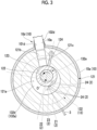
- a plurality of injection holes 24 in the present embodiment are formed. As shown in Figs. 2 and 3 , the plurality of injection holes 24 extend in the axial direction Da and are arranged at equal intervals in the circumferential direction of the rotary shaft 11. As shown in Fig. 3 , in the present embodiment, a case where four injection holes 24 are disposed is illustrated as an example.
- the opening portions of the plurality of injection holes 24 are disposed on the side where the opening portions of the discharge holes 131e and 132e are disposed.
- the opening portions of the plurality of injection holes 24 that open into the compression chamber 121a are disposed in a range of, for example, 200° to 300° in which the phase angle with respect to the axis line O.
- the port 21, the intermediate pressure chamber 22, and the lower bearing cover portion 132b of the lower bearing 132 of the injection portion 2 are disposed in the axial direction Da in order of port 21, intermediate pressure chamber 22, lower bearing cover portion 132b.
- the port 21, the intermediate pressure chamber 22, and the lower bearing cover portion 132b are disposed in order of the port 21, the intermediate pressure chamber 22, and the lower bearing cover portion 132b in a direction away from the compression chamber 121a.
- the check valve 23 can be disposed in the intermediate pressure chamber 22. Accordingly, for example, the length of the flow path of the refrigerant between the compression chamber 121a and the check valve 23 can be shortened as compared with a case where the check valve 23 is disposed in the injection pipe 3 or the like outside the bearing portion 13. Therefore, it is possible to suppress the generation of dead volume.
- the injection holes 24 opening into the compression chamber 121a can be disposed in the circumferential direction. The injection holes 24 can be disposed with a high degree of freedom.
- the length of the injection holes 24 can be formed to be the shortest. Therefore, it is possible to further suppress the generation of dead volume.
- the injection holes 24 are formed in a plurality of the injection holes 24, the amount of refrigerant that can be supplied to the compression chamber 121a can be increased.
- the plurality of injection holes 24 are arranged at equal intervals in the circumferential direction of the rotary shaft 11, the time when each injection hole 24 opens in the compression chamber 121a in the process of compressing the refrigerant can be aligned. Therefore, it is possible to improve the supply efficiency of the refrigerant to the compression chamber 121a by the injection portion 2.
- the intermediate pressure chamber 22 can be opened without passing through the port 21 in a case where the lower bearing cover portion 132b is removed from the lower bearing main body 132a. That is, the check valve 23 disposed in the intermediate pressure chamber 22 can be accessed by removing the lower bearing cover portion 132b. As a result, the check valve 23 can be easily maintained without removing the lower bearing 132 from the cylinder 121 or the like.
- the compressor 100 is a twin rotary compressor having two compression chambers 121a.
- the compressor 100 includes a compressor main body 1, an injection portion 2, a first injection pipe 31, a second injection pipe 32, an accumulator 4, a first suction pipe 51, a second suction pipe 52, a discharge pipe 6, and a leg portion 7.
- the compressor main body 1 includes a housing 10, a rotary shaft 11, a rotary compression portion 12a, a bearing portion 13, and an electric motor 14.
- the housing 10 includes a main body portion 10a, an upper cover portion 10b, a lower cover portion 10c, a first refrigerant introduction portion 10h, a second refrigerant introduction portion 10i, a first suction port 10f, and a second suction port 10g.
- the first refrigerant introduction portion 10h has a first side surface opening 101h formed to penetrate the main body portion 10a in the thickness direction of the main body portion 10a, and a first tubular portion 131c disposed inside the first side surface opening 101h.
- the first side surface opening 101h has a circular shape as an opening.
- the first cylindrical portion 102h is fitted to the first side surface opening 101h without a gap and extends from the first side surface opening 101h to the outside of the main body portion 10a.
- the first suction port 10f is a member that is disposed inside the first cylindrical portion 102h of the first refrigerant introduction portion 10h and has a syringe shape.
- the first suction port 10f is fitted to the first cylindrical portion 102h without a gap.
- a distal end of the first suction port 10f extends toward the inside of the main body portion 10a with respect to the first cylindrical portion 102h.
- the rear end of the first suction port 10f is flush with, for example, the opening portion of the first cylindrical portion 102h.
- the second refrigerant introduction portion 10i is disposed on the lower side Dvd (the other side Dad) than the first refrigerant introduction portion 10h.
- the second refrigerant introduction portion 10i has a second side surface opening 101i that is formed to penetrate the main body portion 10a in the thickness direction of the main body portion 10a, and a second cylindrical portion 102i that is disposed inside the second side surface opening 101i.
- the second side surface opening 101i has a circular opening.
- the second cylindrical portion 102i is fitted to the second side surface opening 101i without a gap, and extends from the second side surface opening 101i to the outside of the main body portion 10a.
- the second suction port 10g is a member that is disposed inside the second cylindrical portion 102i of the second refrigerant introduction portion 10i and has a syringe shape.
- the second suction port 10g is fitted to the second cylindrical portion 102i without a gap.
- the distal end of the second suction port 10g extends toward the inside of the main body portion 10a with respect to the second cylindrical portion 102i.
- the rear end of the second suction port 10g is flush with, for example, the opening portion of the second cylindrical portion 102i.
- the refrigerant in the accumulator 4 is guided to the inside of the housing 10 through a first suction pipe 51 that connects the accumulator 4 and the first suction port 10f and a second suction pipe 52 that connects the accumulator 4 and the second suction port 10g.
- One end of the first suction pipe 51 and the second suction pipe 52 extends in the accumulator 4.
- the other end of the first suction pipe 51 is inserted into the first suction port 10f, and the other end of the second suction pipe 52 is inserted into the second suction port 10g.
- the rotary compression portion 12a includes a first cylinder 120a, a second cylinder 120d, a first eccentric shaft portion 122a, a second eccentric shaft portion 122b, a first piston rotor 123a, a second piston rotor 123b, an intermediate plate 125, and a blade (not shown).
- the first cylinder 120a is a member that has an annular shape and extends in the axial direction Da in a case of being accommodated in the housing 10.
- the first cylinder 120a is fixed to a portion of the inner peripheral surface of the main body portion 10a of the housing 10 on the lower side Dvd.
- a space in the first cylinder 120a defined by the inner peripheral surface of the first cylinder 120a is the first compression chamber 120b that compresses the refrigerant. That is, the first cylinder 120a is formed with a cylindrical first compression chamber 120b extending in the axial direction Da.
- a first suction hole 120c that penetrates from an inner peripheral surface to an outer peripheral surface of the first cylinder 120a is formed in the first cylinder 120a.
- the above-described distal end of the first suction port 10f of the first refrigerant introduction portion 10h is inserted into the first suction hole 120c without a gap. Therefore, the refrigerant is introduced into the first compression chamber 120b through the first suction port 10f.
- a blade groove (not shown) that extends from an inner peripheral surface to an outer peripheral surface and in which a blade is disposed on an inner side is formed in the first cylinder 120a.
- the first eccentric shaft portion 122a is a member that is provided integrally with the rotary shaft 11 and has a cylindrical shape.
- the first eccentric shaft portion 122a is disposed in the compression chamber 121a at a position offset in a direction orthogonal to the axis line O about which the rotary shaft 11 is centered from the axis line O.
- the first piston rotor 123a is a member having a cylindrical shape having an outer diameter smaller than the inner diameter of the first cylinder 120a.
- the first piston rotor 123a extends in the axial direction Da.
- the first piston rotor 123a is provided in the first eccentric shaft portion 122a.
- the first eccentric shaft portion 122a is disposed inside the first piston rotor 123a integrally with the first piston rotor 123a.
- the first piston rotor 123a rotates together with the first eccentric shaft portion 122a in a state of being eccentric with respect to the axis line O in accordance with the rotation of the rotary shaft 11.
- the first piston rotor 123a is eccentrically rotated in the first compression chamber 120b due to the rotation of the rotary shaft 11, similarly to the piston rotor 123 described in the first embodiment.
- the second cylinder 120d is a member that has an annular shape and extends in the axial direction Da in a case of being accommodated in the housing 10.
- the second cylinder 120d is fixed to a portion of the inner peripheral surface of the main body portion 10a of the housing 10 on the lower side Dvd with respect to the first cylinder 120a.
- a space inside the second cylinder 120d defined by the inner peripheral surface of the second cylinder 120d is the second compression chamber 120e in which the refrigerant is compressed. That is, the second cylinder 120d is formed with a cylindrical second compression chamber 120e extending in the axial direction Da.
- a second suction hole 120f that penetrates from an inner peripheral surface to an outer peripheral surface of the second cylinder 120d is formed in the second cylinder 120d.
- the distal end of the second suction port 10g of the refrigerant introduction portion 10i is inserted into the second suction hole 120f without a gap. Therefore, the refrigerant is introduced into the second compression chamber 120e through the second suction port 10g.
- a blade groove (not shown) that extends from an inner peripheral surface to an outer peripheral surface and in which the blade is disposed on the inner side is formed in the second cylinder 120d.
- the second eccentric shaft portion 122b is a member that is provided integrally with the rotary shaft 11 and has a cylindrical shape.
- the second eccentric shaft portion 122b is disposed in the second compression chamber 120e at a position offset in a direction orthogonal to the axis line O about which the rotary shaft 11 is centered from the axis line O.
- the second eccentric shaft portion 122b in the present embodiment is, for example, offset in a direction opposite to a direction in which the first eccentric shaft portion 122a is offset from the rotary shaft 11.
- Each of the second piston rotors 123b is a member having a cylindrical shape with an outer diameter smaller than the inner diameter of the second cylinder 120d.
- the second piston rotor 123b extends in the axial direction Da.
- the second piston rotor 123b is provided in the second eccentric shaft portion 122b.
- the second eccentric shaft portion 122b is disposed inside the second piston rotor 123b integrally with the second piston rotor 123b.
- the second piston rotor 123b rotates together with the second eccentric shaft portion 122b in a state of being eccentric with respect to the axis line O in accordance with the rotation of the rotary shaft 11. Similar to the piston rotor 123 described in the first embodiment, the second piston rotor 123b is eccentrically rotated in the second compression chamber 120e due to the rotation of the rotary shaft 11.
- the intermediate plate 125 is disposed between the first cylinder 120a and the second cylinder 120d, and is a member that isolates the first compression chamber 120b formed in the first cylinder 120a from the second compression chamber 120e formed in the second cylinder 120d.
- the intermediate plate 125 in the present embodiment has a cylindrical shape and is fixed to an inner surface of the main body portion 10a of the housing 10.
- the upper bearing 131 is provided in the first cylinder 120a on the one side Dau with respect to the first cylinder 120a and rotatably supports the rotary shaft 11 in the housing 10.
- the lower bearing 132 is provided in the second cylinder 120d on the other side Dad with respect to the second cylinder 120d and rotatably supports the rotary shaft 11 in the housing 10. Therefore, the upper bearing 131 and the lower bearing 132 are disposed so as to sandwich the first cylinder 120a and the second cylinder 120d from the axial direction Da.
- the upper bearing 131 is fixed to the first cylinder 120a from the one side Dau in a state of being slidably surround the rotary shaft 11 from the outer peripheral side.
- the lower bearing 132 is fixed to the second cylinder 120d from the other side Dad in a state of being slidably surround the rotary shaft 11 from the outer peripheral side.
- the upper bearing 131 includes an upper bearing main body 131a and an upper bearing cover portion 131b.
- the upper bearing main body 131a includes a first tubular portion 131c and a first flange portion 131d.
- the first tubular portion 131c has a cylindrical shape extending in the axial direction Da in a case where the upper bearing 131 is provided in the first cylinder 120a.
- the first tubular portion 131c is slidably surround the rotary shaft 11 from the outer peripheral side.
- the first flange portion 131d is a member that is integrally formed with the first tubular portion 131c and spreads from the first tubular portion 131c in a radial direction of the rotary shaft 11.
- the first flange portion 131d is fixed to a surface of the first cylinder 120a facing the other side Dad by a fastening portion such as a bolt.
- the first flange portion 131d is disposed in the other side Dad of the first tubular portion 131c.
- the first flange portion 131d has an annular shape as viewed in the axial direction Da.
- a recess 131f that is recessed toward the other side Dad and extends in a circumferential direction of the rotary shaft 11 is formed on a surface of the first flange portion 131d facing the one side Dad.
- the upper bearing cover portion 131b is provided on a surface facing the one side Dau of the first flange portion 131d so as to close the recess 131f formed in the first flange portion 131d from the one side Dau.
- the upper bearing cover portion 131b is provided in the first flange portion 131d so as to surround the first tubular portion 131c from the outer peripheral side.
- the upper bearing cover portion 131b can be attached to and detached from the first flange portion 131d.
- the upper bearing cover portion 131b is fixed to the first flange portion 131d by, for example, a fastening portion such as a bolt.
- the lower bearing 132 includes a lower bearing main body 132a and a lower bearing cover portion 132b.
- the lower bearing main body 132a includes a second tubular portion 132c and a second flange portion 132d.
- the second tubular portion 132c has a cylindrical shape extending in the axial direction Da in a case where the lower bearing 132 is provided in the second cylinder 120d.
- the second tubular portion 132c is slidable on the outer peripheral side of the rotary shaft 11.
- the second flange portion 132d is a member that is integrally formed with the second tubular portion 132c and spreads from the second tubular portion 132c in a radial direction of the rotary shaft 11.
- the second flange portion 132d is fixed to a surface of the second cylinder 120d facing the other side Dad by a fastening portion such as a bolt.
- the second flange portion 132d is disposed in a portion of the second tubular portion 132c on the one side Dau.
- the second flange portion 132d has an annular shape as viewed in the axial direction Da.
- a recess 132f that is recessed toward the one side Dau and extends in a circumferential direction of the rotary shaft 11 is formed on a surface of the second flange portion 132d facing the other side Dad.
- the lower bearing cover portion 132b is provided on a surface of the second flange portion 132d facing the other side Dad so as to close the recess 132f formed in the second flange portion 132d from the other side Dad.
- the lower bearing cover portion 132b is provided in the second flange portion 132d so as to surround the second tubular portion 132c from the outer peripheral side.
- the lower bearing cover portion 132b can be attached to and detached from the second flange portion 132d.
- the lower bearing cover portion 132b is fixed to the second flange portion 132d by, for example, a fastening portion such as a bolt.
- the injection portion 2 includes a first injection portion 20a formed in the upper bearing 131 and a second injection portion 20b formed in the lower bearing 132.
- the first injection portion 20a includes a first port 21a, a first intermediate pressure chamber 22a, a first check valve 23a, and a first injection hole 24a.
- the first port 21a is a hole formed in the first flange portion 131d of the upper bearing 131.
- the first port 21a extends from the outer peripheral surface of the first flange portion 131d to the inner surface of the recess 131f formed in the first flange portion 131d. Therefore, the first port 21a is opened to each of the outer peripheral surface of the first flange portion 131d and the inner surface of the recess 131f.
- a first injection pipe 31 for supplying a refrigerant is connected to an opening of the first port 21a formed in the outer peripheral surface of the first flange portion 131d. Therefore, the refrigerant from the outside is supplied to the first port 21a through the first injection pipe 31.
- the first injection pipe 31 penetrates the main body portion 10a of the housing 10 and is connected to a device (not shown) that is disposed outside the housing 10 and supplies a refrigerant for injection.
- the first intermediate pressure chamber 22a is a chamber formed in the upper bearing 131.
- the first intermediate pressure chamber 22a is the recess 131f formed in the first flange portion 131d.
- the first intermediate pressure chamber 22a is defined by closing the recess 131f formed in the first flange portion 131d by the upper bearing cover portion 131b. Therefore, the first intermediate pressure chamber 22a is opened by removing the upper bearing cover portion 131b from the upper bearing main body 131a.
- the refrigerant that flows through the first port 21a flows into the first intermediate pressure chamber 22a.
- the first check valve 23a is provided in the first intermediate pressure chamber 22a and is a reed valve for preventing the refrigerant that has flowed into the first intermediate pressure chamber 22a from the port 21 from flowing back to the first port 21a.
- the first check valve 23a is disposed in the first intermediate pressure chamber 22a so as to block an opening portion of the first port 21a that opens into the first intermediate pressure chamber 22a.
- the first injection hole 24a is a hole that communicates the first intermediate pressure chamber 22a with the first compression chamber 120b formed in the first cylinder 120a.
- the first injection hole 24a extends from the inner surface facing the one side Dau in the first intermediate pressure chamber 22a to the other side Dad in the first compression chamber 120b.
- the first injection hole 24a is opened in each of the inner surface of the recess 131f and the surface of the first flange portion 131d facing the other side Dda.
- the first port 21a, the first intermediate pressure chamber 22a, and the upper bearing cover portion 131b of the upper bearing 131 of the first injection portion 20a are disposed in order of the first port 21a, the first intermediate pressure chamber 22a, and the upper bearing cover portion 131b in the axial direction Da.
- the first port 21a, the first intermediate pressure chamber 22a, and the upper bearing cover portion 131b are disposed in order of the first port 21a, the first intermediate pressure chamber 22a, and the upper bearing cover portion 131b in a direction away from the first compression chamber 120b.
- the second injection portion 20b includes a second port 21b, a second intermediate pressure chamber 22b, a second check valve 23b, and a second injection hole 24b.
- the second port 21b is a hole formed in the second flange portion 132d of the lower bearing 132.
- the second port 21b extends from the outer peripheral surface of the second flange portion 132d to the inner surface of the recess 132f formed in the second flange portion 132d. Therefore, the second port 21b is opened to each of the outer peripheral surface of the second flange portion 132d and the inner surface of the recess 132f.
- An opening of the second port 21b formed in the outer peripheral surface of the second flange portion 132d is connected to the second injection pipe 32 for supplying the refrigerant. Therefore, the refrigerant from the outside is supplied to the second port 21b through the second injection pipe 32.
- the second injection pipe 32 penetrates the main body portion 10a of the housing 10 and is connected to a device (not shown) or the like disposed outside the housing 10 to supply a refrigerant for injection.
- the second intermediate pressure chamber 22b is a chamber formed in the lower bearing 132.
- the second intermediate pressure chamber 22b is the recess 132f formed in the second flange portion 132d.
- the second intermediate pressure chamber 22b is defined by closing the recess 132f formed in the second flange portion 132d by the lower bearing cover portion 132b. Therefore, the second intermediate pressure chamber 22b is opened by removing the lower bearing cover portion 132b from the lower bearing main body 132a. The refrigerant that flows through the second port 21b flows into the second intermediate pressure chamber 22b.
- the second check valve 23b is provided in the second intermediate pressure chamber 22b and is a reed valve for preventing the refrigerant that has flowed into the second intermediate pressure chamber 22b from the port 21 from flowing back to the second port 21b.
- the second check valve 23b is disposed in the second intermediate pressure chamber 22b so as to block an opening portion of the second port 21b that opens into the second intermediate pressure chamber 22b.
- the second injection hole 24b is a hole that communicates the second intermediate pressure chamber 22b with the second compression chamber 120e formed in the second cylinder 120d.
- the second injection hole 24b extends from the inner surface facing the other side Dad in the second intermediate pressure chamber 22b to the other side Dad in the second compression chamber 120e.
- the first injection hole 24a is open to each of the inner surface of the recess 132f and the surface of the second flange portion 132d facing the one side Dau.
- the second port 21b, the second intermediate pressure chamber 22b, and the lower bearing cover portion 132b of the lower bearing 132 of the second injection portion 20b are disposed in order of the second port 21b, the second intermediate pressure chamber 22b, and the lower bearing cover portion 132b in the axial direction Da.
- the second port 21b, the second intermediate pressure chamber 22b, and the lower bearing cover portion 132b are disposed in order of the second port 21b, the second intermediate pressure chamber 22b, and the lower bearing cover portion 132b in a direction away from the second compression chamber 120e.
- the configuration described in the second embodiment can also achieve the same operations and effects as those described in the first embodiment.
- the injection portion 2 described in the first embodiment may be formed only in the upper bearing 131. Therefore, for example, the configuration may be adopted in which the injection portion 2 described in the first embodiment is not formed in the lower bearing 132 and only the first injection portion 20a described in the second embodiment is formed in the upper bearing 131 described in the first embodiment.
- the injection portion 2 may be formed in both the upper bearing 131 and the lower bearing 132. Therefore, for example, a configuration may be adopted in which the injection portion 2 described in the first embodiment is not formed in the lower bearing 132, the first injection portion 20a described in the second embodiment is formed in the upper bearing 131 described in the first embodiment, and the second injection portion 20b described in the second embodiment is formed in the lower bearing 132 described in the first embodiment.
- the injection portion 2 capable of supplying the refrigerant to each of the first compression chamber 120b and the second compression chamber 120e may be formed in the intermediate plate 125 described in the second embodiment.
- the length of the flow path of the refrigerant between the compression chamber 121a and the check valve 23 disposed in the intermediate pressure chamber 22 can be shortened as compared with a case where the check valve 23 is disposed in the flow path for supplying the refrigerant disposed outside the bearing portion 13.
- the intermediate pressure chamber 22 formed in the bearing portion 13 extends in the circumferential direction, the injection holes 24 opening into the compression chamber 121a can be disposed in the circumferential direction.
- the rotary compressor 100 according to a second aspect is the rotary compressor 100 according to (1), in which the plurality of injection holes 24 may extend in the axial direction Da and may be arranged at equal intervals in the circumferential direction.
- the rotary compressor 100 according to a third aspect is the rotary compressor 100 according to (1) or (2), in which the bearing portion 13 includes a bearing main body in which the injection portion 2 is formed, and a cover portion that is provided to be attachable to and detachable from the bearing main body and that opens the intermediate pressure chamber 22 by being removed from the bearing main body, and the port 21, the intermediate pressure chamber 22, and the cover portion are disposed in order of the port 21, the intermediate pressure chamber 22, and the cover portion in a direction away from the compression chamber 121a.
- the intermediate pressure chamber 22 can be opened without passing through the port 21.
- the cover portion can be removed to access the check valve 23 disposed in the intermediate pressure chamber 22.
Landscapes
- Engineering & Computer Science (AREA)
- Mechanical Engineering (AREA)
- General Engineering & Computer Science (AREA)
- Applications Or Details Of Rotary Compressors (AREA)
Abstract
Description
- The present disclosure relates to a rotary compressor.
- This application claims priority to
Japanese Patent Application No. 2022-124761, filed in Japan on August 4, 2022 - For example,
PTL 1 discloses a twin rotary compressor in which an injection refrigerant is supplied to each of a first compression chamber and a second compression chamber through an injection flow path. - In the injection flow path, the injection refrigerant is supplied to the first compression chamber through the first injection pipe connected to the injection muffler and the hole (first common hole, and first jet hole and second jet hole connected to the first common hole) formed in an upper bearing. In addition, the injection refrigerant is supplied to the second compression chamber through the second injection pipe connected to the injection muffler and the hole (the second common hole, the third jet hole, and the fourth jet hole connected to the second common hole) formed in the lower bearing.
- The injection muffler is provided to suppress the refrigerant from flowing back from the compression chamber through the hole of the bearing in a case where the refrigerant is compressed in each compression chamber by communicating the first compression chamber with the second compression chamber such that a pressure difference does not occur. Accordingly, the injection refrigerant having a larger flow rate can be allowed to flow into the compression chamber.
- [PTL 1] International Publication No.
WO2020/031248 - By the way, in a case where the compression chamber is one of the rotary compressors, a check valve or the like may be disposed in a supply flow path of the injection refrigerant in order to suppress the injection refrigerant from flowing back from the compression chamber. In this case, since the refrigerant existing in the section from the compression chamber to the check valve in the supply flow path is not compressed in the compression chamber, this section is a dead volume that causes a decrease in the efficiency of the compressor.
- For example, in order to reduce the dead volume that causes a decrease in compression efficiency, it is currently difficult to dispose a check valve inside a hole formed in the bearing because the inside of the hole is a narrow space. Therefore, there is a problem that a check valve needs to be disposed in a supply flow path that is connected to the hole of the bearing from the outside.
- In addition, in the technique disclosed in
PTL 1, the common holes (first common hole and second common hole) are formed in a straight line. Therefore, in a case where the number of holes (first jet holes, second jet holes, third jet holes, and fourth jet holes) for injection is increased for the purpose of increasing the flow rate, there is a problem that the arrangement of the holes is limited to a straight line. - The present disclosure has been made to solve the above-described problems, and an object of the present disclosure is to provide a rotary compressor capable of disposing injection holes with a high degree of freedom while suppressing the occurrence of dead volume.
- In order to achieve the above object, a rotary compressor according to the present disclosure includes a rotary shaft that is rotatable about an axis line; a cylinder in which a compression chamber that compresses a refrigerant with rotation of the rotary shaft is formed; a bearing portion that is provided in the cylinder and rotatably supports the rotary shaft; and an injection portion that is formed in the bearing portion and is capable of supplying the refrigerant into the compression chamber, in which the injection portion includes a port through which the refrigerant supplied from an outside flows, an intermediate pressure chamber that extends in a circumferential direction of the rotary shaft and into which the refrigerant is introduced from the port, a check valve that is provided in the intermediate pressure chamber and prevents the refrigerant in the intermediate pressure chamber from flowing back to the port, and a plurality of injection holes through which the intermediate pressure chamber communicates with the compression chamber.
- According to the present disclosure, it is possible to provide a rotary compressor in which an injection hole can be disposed with a high degree of freedom while suppressing the generation of a dead volume.
-
-
Fig. 1 is a vertical cross-sectional view for explaining a configuration of a rotary compressor according to a first embodiment of the present disclosure. -
Fig. 2 is an enlarged view of a main portion inFig. 1 . -
Fig. 3 is a diagram illustrating a cross-sectional view taken along the direction of the line III-III inFig. 2 . -
Fig. 4 is a vertical cross-sectional view for explaining a configuration of a rotary compressor according to a second embodiment of the present disclosure, and is a part corresponding toFig. 2 . - Hereinafter, an embodiment of the rotary compressor according to the present disclosure will be described with reference to the accompanying drawings.
- The rotary compressor is, for example, a sealed electric rotary compressor used for an air conditioner, a refrigerating apparatus, or the like.
- As shown in
Fig. 1 , therotary compressor 100 includes a compressormain body 1, aninjection portion 2, aninjection pipe 3, anaccumulator 4, asuction pipe 5, adischarge pipe 6, andleg portion 7. - Hereinafter, the
rotary compressor 100 will be simply referred to as a "compressor 100". - As the refrigerant compressed by the
compressor 100, for example, a hydrofluoroolefin (HFO) refrigerant such as R32 or R454C, or a natural refrigerant such as CO2, propane, or helium can be used. - The compressor
main body 1 compresses a refrigerant supplied from the outside. - The compressor
main body 1 includes ahousing 10, arotary shaft 11, arotary compression portion 12, abearing portion 13, and anelectric motor 14. - The
housing 10 is a pressure vessel extending in a vertical direction Dv (an up-down direction inFig. 1 ) in a case where thecompressor 100 is provided on a floor surface, a ground surface, or the like. Thehousing 10 forms an outer shell of the compressormain body 1. Hereinafter, for convenience of description, an upper side in the vertical direction Dv will be simply referred to as an "upper side Dvu", and a lower side in the vertical direction Dv will be simply referred to as a "lower side Dvd". - The
housing 10 includes amain body portion 10a, anupper cover portion 10b, alower cover portion 10c, arefrigerant introduction portion 10d, and asuction port 10e. - The
main body portion 10a has a cylindrical shape extending in the vertical direction Dv. Therefore, themain body portion 10a has openings on both the upper side Dvu and the lower side Dvd. - The
upper cover portion 10b is provided in themain body portion 10a so as to close the opening on the upper side Dvu in themain body portion 10a from the upper side Dvu. - The
lower cover portion 10c is provided in themain body portion 10a so as to close the opening on the lower side Dvd in themain body portion 10a from the lower side Dvd. In thelower cover portion 10c, aleg portion 7 is provided, and theentire housing 10 is supported by theleg portion 7. - The
refrigerant introduction portion 10d is a hole for introducing the refrigerant from the outside to the inside of themain body portion 10a. - The
refrigerant introduction portion 10d has a side surface opening 101d formed to penetrate themain body portion 10a in the thickness direction of themain body portion 10a, and acylindrical portion 102d disposed inside the side surface opening 101d. - The side surface opening 101d has a circular shape as an opening. The side surface opening 101d is disposed in a portion of the
main body portion 10a on the lower side Dvd. Thecylindrical portion 102d is fitted into the side surface opening 101d without a gap and extends from the side surface opening 101d to the outside of themain body portion 10a. - The
suction port 10e is a member that is disposed inside thecylindrical portion 102d of therefrigerant introduction portion 10d and has a syringe shape. Thesuction port 10e is fitted to thecylindrical portion 102d without a gap. The distal end of thesuction port 10e extends toward the inside of themain body portion 10a with respect to thecylindrical portion 102d. The rear end of thesuction port 10e is flush with, for example, the opening portion of thecylindrical portion 102d. - Here, an
accumulator 4 for gas-liquid separation of the refrigerant before supplying the refrigerant to the compressormain body 1 is disposed outside thehousing 10. Theaccumulator 4 is fixed to themain body portion 10a in thehousing 10, for example, via the bracket Br. - The refrigerant in the
accumulator 4 is guided into thehousing 10 through thesuction pipe 5 connecting theaccumulator 4 and thesuction port 10e. One end of thesuction pipe 5 extends into theaccumulator 4. The other end of thesuction pipe 5 is inserted into thesuction port 10e. - The
rotary shaft 11 is accommodated in thehousing 10.Rotary shaft 11 can be rotated about an axis line O extending in the vertical direction Dv. For convenience of description, a direction in which the axis line O about therotary shaft 11 extends will be referred to as an axial direction Da. In addition, the one side Dau in the axial direction Da will be simply referred to as "one side Dau", and the other side Dad in the axial direction Da will be simply referred to as "the other side Dad". The axial direction Da in the present embodiment coincides with the vertical direction Dv, the one side Dau coincides with the upper side Dvu, and the other side Dad coincides with the lower side Dvd. - The
rotary compression portion 12 is accommodated in thehousing 10 and compresses the refrigerant introduced by therefrigerant introduction portion 10d. Therotary compression portion 12 is disposed in a portion of themain body portion 10a of thehousing 10 on the lower side Dvd. - The
rotary compression portion 12 includes acylinder 121, aneccentric shaft portion 122, apiston rotor 123, and a blade 124 (seeFig. 3 ). - The
cylinder 121 is a member that has an annular shape and extends in the axial direction Da in a case of being accommodated in thehousing 10. Thecylinder 121 is fixed to a lower side Dvd portion of the inner peripheral surface of themain body portion 10a of thehousing 10. A space inside thecylinder 121 defined by the inner peripheral surface of thecylinder 121 is thecompression chamber 121a that compresses the refrigerant. That is, thecylinder 121 is formed with acylindrical compression chamber 121a extending in the axial direction Da. - Further, the
cylinder 121 is formed withsuction holes 121b that penetrate from the inner peripheral surface to the outer peripheral surface of thecylinder 121. The above-described distal end of thesuction port 10e of therefrigerant introduction portion 10d is inserted into thesuction hole 121b without a gap. Therefore, the refrigerant is introduced into thecompression chamber 121a through thesuction port 10e. In addition, ablade groove 121c (seeFig. 3 ) that extends from the inner peripheral surface to the outer peripheral surface of thecylinder 121 and in which theblade 124 is disposed on the inner side is formed in thecylinder 121. - The
eccentric shaft portion 122 is a cylindrical member that is provided integrally with the lower end portion of therotary shaft 11. Theeccentric shaft portion 122 is disposed in thecompression chamber 121a at a position offset in a direction orthogonal to the axis line O about which therotary shaft 11 is centered from the axis line O. - The
piston rotor 123 is a member having a cylindrical shape with an outer diameter smaller than the inner diameter of thecylinder 121. Thepiston rotor 123 extends in the axial direction Da. Thepiston rotor 123 is provided in theeccentric shaft portion 122. Inside thepiston rotor 123, theeccentric shaft portion 122 is disposed integrally with thepiston rotor 123. Thepiston rotor 123 rotates together with theeccentric shaft portion 122 in a state of being eccentric with respect to the axis line O in accordance with the rotation of therotary shaft 11. - As shown in
Fig. 3 , theblade 124 is a member that is disposed in theblade groove 121c formed in thecylinder 121 and has a plate shape. Theblade 124 is guided to be slidable on an inner surface of theblade groove 121c and is held movably back and forth in the radial direction of therotary shaft 11. - The
blade 124 is elastically pressed toward the radial inner side of therotary shaft 11 by a compression spring (not shown) disposed in theblade groove 121c. Theblade 124 during the operation of thecompressor 100 is pressed by the compression spring, so that the inner end edge in the radial direction is always in contact with the outer peripheral surface of thepiston rotor 123. - Here, the
eccentric shaft portion 122 has an outer diameter slightly smaller than the inner diameter of thepiston rotor 123. Accordingly, in a case where therotary shaft 11 rotates, theeccentric shaft portion 122 revolves about the axis line O, and thepiston rotor 123 eccentrically rotates in thecompression chamber 121a of thecylinder 121. In a case where theblades 124 advance in the radial direction with the eccentric rotation of thepiston rotor 123, theblades 124 come into contact with thepiston rotor 123. By theblade 124 comes into contact with thepiston rotor 123, theblade 124, together with thepiston rotor 123, partitions the inside of thecompression chamber 121a into two regions. - Hereinafter, the position of the
piston rotor 123 in a case where theentire blade 124 is accommodated in theblade groove 121c is referred to as an "initial position". That is, in the initial position, theblade 124 is in a state of not advancing into thecompression chamber 121a. In addition, in the present embodiment, the phase angle of thepiston rotor 123 in the initial position with respect to the axis line O is set to 0°. That is, thepiston rotor 123 eccentrically rotates with the rotation of therotary shaft 11, so that the phase angle of thepiston rotor 123 with respect to the axis line O changes in a range of 0° to 360° counterclockwise as viewed from the upper side Dvu around the axis line O. - In a case where the refrigerant supplied from the
suction port 10e of therefrigerant introduction portion 10d is introduced into thecompression chamber 121a, the volume of one region of the two regions in thecompression chamber 121a partitioned by thepiston rotor 123 and theblade 124 gradually decreases due to the eccentric rotation of thepiston rotor 123. As a result, the refrigerant present in one region is gradually compressed. - As shown in
Figs. 1 and2 , the bearingportion 13 supports therotary shaft 11 to be rotatable in thehousing 10. The bearingportions 13 are provided in thecylinder 121 and are disposed in pairs so as to sandwich thecylinder 121 from the axial direction Da. - Hereinafter, in the pair of bearing
portions 13, the bearingportion 13 disposed on the one side Dau (upper side Dvu) with respect to thecylinder 121 will be referred to as an "upper bearing 131", and the bearingportion 13 disposed on the other side Dad (lower side Dvd) with respect to thecylinder 121 will be referred to as a "lower bearing 132". - As shown in
Fig. 2 , theupper bearing 131 is fixed to thecylinder 121 from the one side Dau in a state of being slidably surround therotary shaft 11 from the outer peripheral side. - The
upper bearing 131 in the present embodiment includes a firsttubular portion 131c and afirst flange portion 131d. - The first
tubular portion 131c has a cylindrical shape extending in the axial direction Da in a case where the bearingportion 13 is provided in thecylinder 121. The firsttubular portion 131c slidably surrounds therotary shaft 11 from the outer peripheral side. - The
first flange portion 131d is a member that is integrally formed with the firsttubular portion 131c and spreads from the firsttubular portion 131c in a radial direction of therotary shaft 11. Thefirst flange portion 131d is disposed in a portion of the other side Dad of the firsttubular portion 131c. Thefirst flange portion 131d has an annular shape as viewed in the axial direction Da. Thefirst flange portion 131d is fixed to a surface of thecylinder 121 facing the one side Dau by, for example, a fastening portion such as a bolt. - The
lower bearing 132 is fixed to thecylinder 121 from the other side Dad in a state of being slidably surround therotary shaft 11 from the outer peripheral side. - The
lower bearing 132 according to the present embodiment includes a lower bearingmain body 132a and a lowerbearing cover portion 132b. - The lower bearing
main body 132a includes a secondtubular portion 132c and asecond flange portion 132d. - The second
tubular portion 132c has a cylindrical shape extending in the axial direction Da in a case where the bearingportion 13 is provided in thecylinder 121. The secondtubular portion 132c slidably surrounds therotary shaft 11 from the outer peripheral side. - The
second flange portion 132d is a member that is integrally formed with the secondtubular portion 132c and spreads from the secondtubular portion 132c in a radial direction of therotary shaft 11. Thesecond flange portion 132d is fixed to a surface of thecylinder 121 facing the other side Dad by a fastening portion such as a bolt. - The
second flange portion 132d is disposed in a portion of the secondtubular portion 132c on the one side Dau. Thesecond flange portion 132d has an annular shape as viewed in the axial direction Da. Arecess 132f that is recessed toward the one side Dau and extends in a circumferential direction of therotary shaft 11 is formed on a surface of thesecond flange portion 132d facing the other side Dad. - The lower
bearing cover portion 132b is provided on a surface of thesecond flange portion 132d facing the other side Dad so as to close therecess 132f formed in thesecond flange portion 132d from the other side Dad. The lowerbearing cover portion 132b is provided in thesecond flange portion 132d so as to surround the secondtubular portion 132c from the outer peripheral side. The lowerbearing cover portion 132b can be attached to and detached from thesecond flange portion 132d. The lowerbearing cover portion 132b is fixed to thesecond flange portion 132d by, for example, a fastening portion such as a bolt. - Here,
discharge holes housing 10 are formed in thefirst flange portion 131d of theupper bearing 131 and thesecond flange portion 132d of the lower bearingmain body 132a. Therefore, thedischarge holes rotary compression portion 12 in thecompression chamber 121a and thehousing 10. - The
discharge hole 131e formed in thefirst flange portion 131d is opened in, for example, a surface facing the other side Dad of thefirst flange portion 131d and an outer peripheral surface of thefirst flange portion 131d. Thedischarge hole 132e formed in thesecond flange portion 132d is opened in, for example, a surface facing the one side Dau of thesecond flange portion 132d and an outer peripheral surface of thesecond flange portion 132d. - For example, a reed valve (not shown) as a discharge valve is disposed at openings of the
discharge holes first flange portion 131d and the outer peripheral surface of thesecond flange portion 132d. The refrigerant that is compressed to increase the pressure to a predetermined pressure pushes open the reed valve and is discharged to the outside of the bearingportion 13 in thehousing 10 through thedischarge holes housing 10 from thedischarge holes compressor 100 through thedischarge pipe 6 provided in theupper cover portion 10b of thehousing 10. - Opening portions of the
discharge holes compression chamber 121a are disposed in a range in which the phase angle with respect to the axis line O is greater than 315° and less than 360°, for example. In addition, the opening portion of thesuction hole 121b that opens into thecompression chamber 121a is disposed in a range in which the phase angle with respect to the axis line O is greater than 0° and less than 45°, for example. - The
electric motor 14 is accommodated in thehousing 10 and rotates therotary shaft 11. - The
electric motor 14 includes arotor 141 and astator 142. - The
rotor 141 is a rotor that is fixed to therotary shaft 11 so as to surround therotary shaft 11 from the outer peripheral side on the upper side Dvu with respect to therotary compression portion 12. Thestator 142 is a stator that is fixed to an inner surface of themain body portion 10a of thehousing 10 so as to surround therotor 141 from the outer peripheral side. A power source (not shown) that supplies power is connected to thestator 142. Theelectric motor 14 rotates therotary shaft 11 by the power supplied from the power source. - The
injection portion 2 is independent of therefrigerant introduction portion 10d and supplies the refrigerant from the outside into thecompression chamber 121a of thecylinder 121. Theinjection portion 2 is formed in thelower bearing 132 of the bearingportion 13. - The
injection portion 2 according to the present embodiment includes aport 21, anintermediate pressure chamber 22, acheck valve 23, and aninjection hole 24. - The
port 21 is a hole formed in thesecond flange portion 132d of thelower bearing 132. Theport 21 extends from the outer peripheral surface of thesecond flange portion 132d to the inner surface of therecess 132f formed in thesecond flange portion 132d. Therefore, theport 21 is opened to each of the outer peripheral surface of thesecond flange portion 132d and the inner surface of therecess 132f. - Here, an
injection pipe 3 for supplying a refrigerant is connected to the opening of theport 21 formed in the outer peripheral surface of thesecond flange portion 132d. Therefore, the refrigerant from the outside is supplied to theport 21 through theinjection pipe 3. Theinjection pipe 3 penetrates themain body portion 10a of thehousing 10 and is connected to a device (not shown) for supplying a refrigerant for injection disposed outside thehousing 10. - The
intermediate pressure chamber 22 is a chamber formed in thelower bearing 132. Theintermediate pressure chamber 22 in the present embodiment is therecess 132f formed in thesecond flange portion 132d. Specifically, theintermediate pressure chamber 22 is defined by closing therecess 132f formed in thesecond flange portion 132d by the lowerbearing cover portion 132b. Therefore, theintermediate pressure chamber 22 is opened by removing the lowerbearing cover portion 132b from the lower bearingmain body 132a. The refrigerant that flows through theport 21 flows into theintermediate pressure chamber 22. - The
check valve 23 is provided in theintermediate pressure chamber 22 and is a reed valve for preventing the refrigerant that has flowed into theintermediate pressure chamber 22 from theport 21 from flowing back to theport 21. Thecheck valve 23 is disposed in theintermediate pressure chamber 22 so as to block an opening portion of theport 21 that opens into theintermediate pressure chamber 22. - The
injection hole 24 is a hole that communicates theintermediate pressure chamber 22 with thecompression chamber 121a formed in thecylinder 121. Theinjection hole 24 extends from an inner surface facing the other side Dad in theintermediate pressure chamber 22 to the one side Dau toward thecompression chamber 121a. Theinjection hole 24 is opened in each of the inner surface of therecess 132f and the surface of thesecond flange portion 132d facing the one side Dau. - A plurality of injection holes 24 in the present embodiment are formed. As shown in
Figs. 2 and3 , the plurality of injection holes 24 extend in the axial direction Da and are arranged at equal intervals in the circumferential direction of therotary shaft 11. As shown inFig. 3 , in the present embodiment, a case where fourinjection holes 24 are disposed is illustrated as an example. - Here, in a case where the
compression chamber 121a is divided into two parts by the side where the opening portion of thesuction hole 121b is disposed and the side where the opening portions of thedischarge holes discharge holes compression chamber 121a are disposed in a range of, for example, 200° to 300° in which the phase angle with respect to the axis line O. - In addition, as shown in
Fig. 2 , theport 21, theintermediate pressure chamber 22, and the lowerbearing cover portion 132b of thelower bearing 132 of theinjection portion 2 are disposed in the axial direction Da in order ofport 21,intermediate pressure chamber 22, lowerbearing cover portion 132b. In other words, theport 21, theintermediate pressure chamber 22, and the lowerbearing cover portion 132b are disposed in order of theport 21, theintermediate pressure chamber 22, and the lowerbearing cover portion 132b in a direction away from thecompression chamber 121a. - In the above configuration, since the
intermediate pressure chamber 22 of theinjection portion 2 is formed in thelower bearing 132, thecheck valve 23 can be disposed in theintermediate pressure chamber 22. Accordingly, for example, the length of the flow path of the refrigerant between thecompression chamber 121a and thecheck valve 23 can be shortened as compared with a case where thecheck valve 23 is disposed in theinjection pipe 3 or the like outside the bearingportion 13. Therefore, it is possible to suppress the generation of dead volume. In addition, since theintermediate pressure chamber 22 formed in thelower bearing 132 extends in the circumferential direction, the injection holes 24 opening into thecompression chamber 121a can be disposed in the circumferential direction. The injection holes 24 can be disposed with a high degree of freedom. - In addition, in the above configuration, since the plurality of injection holes 24 extend from the
intermediate pressure chamber 22 in the axial direction Da, the length of the injection holes 24 can be formed to be the shortest. Therefore, it is possible to further suppress the generation of dead volume. In addition, since the injection holes 24 are formed in a plurality of the injection holes 24, the amount of refrigerant that can be supplied to thecompression chamber 121a can be increased. Further, since the plurality of injection holes 24 are arranged at equal intervals in the circumferential direction of therotary shaft 11, the time when eachinjection hole 24 opens in thecompression chamber 121a in the process of compressing the refrigerant can be aligned. Therefore, it is possible to improve the supply efficiency of the refrigerant to thecompression chamber 121a by theinjection portion 2. - In addition, in the above configuration, since the
port 21, theintermediate pressure chamber 22, and the lowerbearing cover portion 132b are disposed in the direction away from thecompression chamber 121a in this order, theintermediate pressure chamber 22 can be opened without passing through theport 21 in a case where the lowerbearing cover portion 132b is removed from the lower bearingmain body 132a. That is, thecheck valve 23 disposed in theintermediate pressure chamber 22 can be accessed by removing the lowerbearing cover portion 132b. As a result, thecheck valve 23 can be easily maintained without removing thelower bearing 132 from thecylinder 121 or the like. - Next, a second embodiment of the
rotary compressor 100 according to the present disclosure will be described with reference toFig. 4 . In the second embodiment described below, configurations common to the first embodiment described above will be denoted by the same reference numerals in the drawings and the description thereof will be omitted. - The
compressor 100 according to the present embodiment is a twin rotary compressor having twocompression chambers 121a. - The
compressor 100 includes a compressormain body 1, aninjection portion 2, afirst injection pipe 31, asecond injection pipe 32, anaccumulator 4, afirst suction pipe 51, asecond suction pipe 52, adischarge pipe 6, and aleg portion 7. - The compressor
main body 1 includes ahousing 10, arotary shaft 11, arotary compression portion 12a, a bearingportion 13, and anelectric motor 14. - The
housing 10 includes amain body portion 10a, anupper cover portion 10b, alower cover portion 10c, a firstrefrigerant introduction portion 10h, a secondrefrigerant introduction portion 10i, afirst suction port 10f, and asecond suction port 10g. - The first
refrigerant introduction portion 10h has a firstside surface opening 101h formed to penetrate themain body portion 10a in the thickness direction of themain body portion 10a, and a firsttubular portion 131c disposed inside the firstside surface opening 101h. - The first
side surface opening 101h has a circular shape as an opening. The first cylindrical portion 102h is fitted to the firstside surface opening 101h without a gap and extends from the first side surface opening 101h to the outside of themain body portion 10a. - The
first suction port 10f is a member that is disposed inside the first cylindrical portion 102h of the firstrefrigerant introduction portion 10h and has a syringe shape. Thefirst suction port 10f is fitted to the first cylindrical portion 102h without a gap. A distal end of thefirst suction port 10f extends toward the inside of themain body portion 10a with respect to the first cylindrical portion 102h. The rear end of thefirst suction port 10f is flush with, for example, the opening portion of the first cylindrical portion 102h. - The second
refrigerant introduction portion 10i is disposed on the lower side Dvd (the other side Dad) than the firstrefrigerant introduction portion 10h. The secondrefrigerant introduction portion 10i has a secondside surface opening 101i that is formed to penetrate themain body portion 10a in the thickness direction of themain body portion 10a, and a secondcylindrical portion 102i that is disposed inside the secondside surface opening 101i. - The second
side surface opening 101i has a circular opening. The secondcylindrical portion 102i is fitted to the secondside surface opening 101i without a gap, and extends from the secondside surface opening 101i to the outside of themain body portion 10a. - The
second suction port 10g is a member that is disposed inside the secondcylindrical portion 102i of the secondrefrigerant introduction portion 10i and has a syringe shape. Thesecond suction port 10g is fitted to the secondcylindrical portion 102i without a gap. The distal end of thesecond suction port 10g extends toward the inside of themain body portion 10a with respect to the secondcylindrical portion 102i. The rear end of thesecond suction port 10g is flush with, for example, the opening portion of the secondcylindrical portion 102i. - The refrigerant in the
accumulator 4 is guided to the inside of thehousing 10 through afirst suction pipe 51 that connects theaccumulator 4 and thefirst suction port 10f and asecond suction pipe 52 that connects theaccumulator 4 and thesecond suction port 10g. One end of thefirst suction pipe 51 and thesecond suction pipe 52 extends in theaccumulator 4. The other end of thefirst suction pipe 51 is inserted into thefirst suction port 10f, and the other end of thesecond suction pipe 52 is inserted into thesecond suction port 10g. - The
rotary compression portion 12a includes afirst cylinder 120a, asecond cylinder 120d, a firsteccentric shaft portion 122a, a secondeccentric shaft portion 122b, afirst piston rotor 123a, asecond piston rotor 123b, anintermediate plate 125, and a blade (not shown). - The
first cylinder 120a is a member that has an annular shape and extends in the axial direction Da in a case of being accommodated in thehousing 10. Thefirst cylinder 120a is fixed to a portion of the inner peripheral surface of themain body portion 10a of thehousing 10 on the lower side Dvd. A space in thefirst cylinder 120a defined by the inner peripheral surface of thefirst cylinder 120a is thefirst compression chamber 120b that compresses the refrigerant. That is, thefirst cylinder 120a is formed with a cylindricalfirst compression chamber 120b extending in the axial direction Da. - In addition, a
first suction hole 120c that penetrates from an inner peripheral surface to an outer peripheral surface of thefirst cylinder 120a is formed in thefirst cylinder 120a. The above-described distal end of thefirst suction port 10f of the firstrefrigerant introduction portion 10h is inserted into thefirst suction hole 120c without a gap. Therefore, the refrigerant is introduced into thefirst compression chamber 120b through thefirst suction port 10f. In addition, a blade groove (not shown) that extends from an inner peripheral surface to an outer peripheral surface and in which a blade is disposed on an inner side is formed in thefirst cylinder 120a. - The first
eccentric shaft portion 122a is a member that is provided integrally with therotary shaft 11 and has a cylindrical shape. The firsteccentric shaft portion 122a is disposed in thecompression chamber 121a at a position offset in a direction orthogonal to the axis line O about which therotary shaft 11 is centered from the axis line O. - The
first piston rotor 123a is a member having a cylindrical shape having an outer diameter smaller than the inner diameter of thefirst cylinder 120a. Thefirst piston rotor 123a extends in the axial direction Da. Thefirst piston rotor 123a is provided in the firsteccentric shaft portion 122a. The firsteccentric shaft portion 122a is disposed inside thefirst piston rotor 123a integrally with thefirst piston rotor 123a. Thefirst piston rotor 123a rotates together with the firsteccentric shaft portion 122a in a state of being eccentric with respect to the axis line O in accordance with the rotation of therotary shaft 11. Thefirst piston rotor 123a is eccentrically rotated in thefirst compression chamber 120b due to the rotation of therotary shaft 11, similarly to thepiston rotor 123 described in the first embodiment. - The
second cylinder 120d is a member that has an annular shape and extends in the axial direction Da in a case of being accommodated in thehousing 10. Thesecond cylinder 120d is fixed to a portion of the inner peripheral surface of themain body portion 10a of thehousing 10 on the lower side Dvd with respect to thefirst cylinder 120a. A space inside thesecond cylinder 120d defined by the inner peripheral surface of thesecond cylinder 120d is thesecond compression chamber 120e in which the refrigerant is compressed. That is, thesecond cylinder 120d is formed with a cylindricalsecond compression chamber 120e extending in the axial direction Da. - In addition, a
second suction hole 120f that penetrates from an inner peripheral surface to an outer peripheral surface of thesecond cylinder 120d is formed in thesecond cylinder 120d. The distal end of thesecond suction port 10g of therefrigerant introduction portion 10i is inserted into thesecond suction hole 120f without a gap. Therefore, the refrigerant is introduced into thesecond compression chamber 120e through thesecond suction port 10g. In addition, a blade groove (not shown) that extends from an inner peripheral surface to an outer peripheral surface and in which the blade is disposed on the inner side is formed in thesecond cylinder 120d. - The second
eccentric shaft portion 122b is a member that is provided integrally with therotary shaft 11 and has a cylindrical shape. The secondeccentric shaft portion 122b is disposed in thesecond compression chamber 120e at a position offset in a direction orthogonal to the axis line O about which therotary shaft 11 is centered from the axis line O. The secondeccentric shaft portion 122b in the present embodiment is, for example, offset in a direction opposite to a direction in which the firsteccentric shaft portion 122a is offset from therotary shaft 11. - Each of the
second piston rotors 123b is a member having a cylindrical shape with an outer diameter smaller than the inner diameter of thesecond cylinder 120d. Thesecond piston rotor 123b extends in the axial direction Da. Thesecond piston rotor 123b is provided in the secondeccentric shaft portion 122b. The secondeccentric shaft portion 122b is disposed inside thesecond piston rotor 123b integrally with thesecond piston rotor 123b. Thesecond piston rotor 123b rotates together with the secondeccentric shaft portion 122b in a state of being eccentric with respect to the axis line O in accordance with the rotation of therotary shaft 11. Similar to thepiston rotor 123 described in the first embodiment, thesecond piston rotor 123b is eccentrically rotated in thesecond compression chamber 120e due to the rotation of therotary shaft 11. - The
intermediate plate 125 is disposed between thefirst cylinder 120a and thesecond cylinder 120d, and is a member that isolates thefirst compression chamber 120b formed in thefirst cylinder 120a from thesecond compression chamber 120e formed in thesecond cylinder 120d. Theintermediate plate 125 in the present embodiment has a cylindrical shape and is fixed to an inner surface of themain body portion 10a of thehousing 10. - The
upper bearing 131 is provided in thefirst cylinder 120a on the one side Dau with respect to thefirst cylinder 120a and rotatably supports therotary shaft 11 in thehousing 10. Thelower bearing 132 is provided in thesecond cylinder 120d on the other side Dad with respect to thesecond cylinder 120d and rotatably supports therotary shaft 11 in thehousing 10. Therefore, theupper bearing 131 and thelower bearing 132 are disposed so as to sandwich thefirst cylinder 120a and thesecond cylinder 120d from the axial direction Da. - The
upper bearing 131 is fixed to thefirst cylinder 120a from the one side Dau in a state of being slidably surround therotary shaft 11 from the outer peripheral side. Thelower bearing 132 is fixed to thesecond cylinder 120d from the other side Dad in a state of being slidably surround therotary shaft 11 from the outer peripheral side. - The
upper bearing 131 includes an upper bearingmain body 131a and an upperbearing cover portion 131b. The upper bearingmain body 131a includes a firsttubular portion 131c and afirst flange portion 131d. - The first
tubular portion 131c has a cylindrical shape extending in the axial direction Da in a case where theupper bearing 131 is provided in thefirst cylinder 120a. The firsttubular portion 131c is slidably surround therotary shaft 11 from the outer peripheral side. Thefirst flange portion 131d is a member that is integrally formed with the firsttubular portion 131c and spreads from the firsttubular portion 131c in a radial direction of therotary shaft 11. Thefirst flange portion 131d is fixed to a surface of thefirst cylinder 120a facing the other side Dad by a fastening portion such as a bolt. Thefirst flange portion 131d is disposed in the other side Dad of the firsttubular portion 131c. Thefirst flange portion 131d has an annular shape as viewed in the axial direction Da. Arecess 131f that is recessed toward the other side Dad and extends in a circumferential direction of therotary shaft 11 is formed on a surface of thefirst flange portion 131d facing the one side Dad. - The upper
bearing cover portion 131b is provided on a surface facing the one side Dau of thefirst flange portion 131d so as to close therecess 131f formed in thefirst flange portion 131d from the one side Dau. The upperbearing cover portion 131b is provided in thefirst flange portion 131d so as to surround the firsttubular portion 131c from the outer peripheral side. The upperbearing cover portion 131b can be attached to and detached from thefirst flange portion 131d. The upperbearing cover portion 131b is fixed to thefirst flange portion 131d by, for example, a fastening portion such as a bolt. - The
lower bearing 132 according to the present embodiment includes a lower bearingmain body 132a and a lowerbearing cover portion 132b. - The lower bearing
main body 132a includes a secondtubular portion 132c and asecond flange portion 132d. - The second
tubular portion 132c has a cylindrical shape extending in the axial direction Da in a case where thelower bearing 132 is provided in thesecond cylinder 120d. The secondtubular portion 132c is slidable on the outer peripheral side of therotary shaft 11. - The
second flange portion 132d is a member that is integrally formed with the secondtubular portion 132c and spreads from the secondtubular portion 132c in a radial direction of therotary shaft 11. Thesecond flange portion 132d is fixed to a surface of thesecond cylinder 120d facing the other side Dad by a fastening portion such as a bolt. - The
second flange portion 132d is disposed in a portion of the secondtubular portion 132c on the one side Dau. Thesecond flange portion 132d has an annular shape as viewed in the axial direction Da. Arecess 132f that is recessed toward the one side Dau and extends in a circumferential direction of therotary shaft 11 is formed on a surface of thesecond flange portion 132d facing the other side Dad. - The lower
bearing cover portion 132b is provided on a surface of thesecond flange portion 132d facing the other side Dad so as to close therecess 132f formed in thesecond flange portion 132d from the other side Dad. The lowerbearing cover portion 132b is provided in thesecond flange portion 132d so as to surround the secondtubular portion 132c from the outer peripheral side. The lowerbearing cover portion 132b can be attached to and detached from thesecond flange portion 132d. The lowerbearing cover portion 132b is fixed to thesecond flange portion 132d by, for example, a fastening portion such as a bolt. - The
injection portion 2 according to the present embodiment includes afirst injection portion 20a formed in theupper bearing 131 and asecond injection portion 20b formed in thelower bearing 132. - The
first injection portion 20a includes afirst port 21a, a first intermediate pressure chamber 22a, afirst check valve 23a, and afirst injection hole 24a. - The
first port 21a is a hole formed in thefirst flange portion 131d of theupper bearing 131. Thefirst port 21a extends from the outer peripheral surface of thefirst flange portion 131d to the inner surface of therecess 131f formed in thefirst flange portion 131d. Therefore, thefirst port 21a is opened to each of the outer peripheral surface of thefirst flange portion 131d and the inner surface of therecess 131f. Afirst injection pipe 31 for supplying a refrigerant is connected to an opening of thefirst port 21a formed in the outer peripheral surface of thefirst flange portion 131d. Therefore, the refrigerant from the outside is supplied to thefirst port 21a through thefirst injection pipe 31. Thefirst injection pipe 31 penetrates themain body portion 10a of thehousing 10 and is connected to a device (not shown) that is disposed outside thehousing 10 and supplies a refrigerant for injection. - The first intermediate pressure chamber 22a is a chamber formed in the
upper bearing 131. The first intermediate pressure chamber 22a is therecess 131f formed in thefirst flange portion 131d. Specifically, the first intermediate pressure chamber 22a is defined by closing therecess 131f formed in thefirst flange portion 131d by the upperbearing cover portion 131b. Therefore, the first intermediate pressure chamber 22a is opened by removing the upperbearing cover portion 131b from the upper bearingmain body 131a. The refrigerant that flows through thefirst port 21a flows into the first intermediate pressure chamber 22a. - The
first check valve 23a is provided in the first intermediate pressure chamber 22a and is a reed valve for preventing the refrigerant that has flowed into the first intermediate pressure chamber 22a from theport 21 from flowing back to thefirst port 21a. Thefirst check valve 23a is disposed in the first intermediate pressure chamber 22a so as to block an opening portion of thefirst port 21a that opens into the first intermediate pressure chamber 22a. - The
first injection hole 24a is a hole that communicates the first intermediate pressure chamber 22a with thefirst compression chamber 120b formed in thefirst cylinder 120a. Thefirst injection hole 24a extends from the inner surface facing the one side Dau in the first intermediate pressure chamber 22a to the other side Dad in thefirst compression chamber 120b. Thefirst injection hole 24a is opened in each of the inner surface of therecess 131f and the surface of thefirst flange portion 131d facing the other side Dda. - The
first port 21a, the first intermediate pressure chamber 22a, and the upperbearing cover portion 131b of theupper bearing 131 of thefirst injection portion 20a are disposed in order of thefirst port 21a, the first intermediate pressure chamber 22a, and the upperbearing cover portion 131b in the axial direction Da. In other words, thefirst port 21a, the first intermediate pressure chamber 22a, and the upperbearing cover portion 131b are disposed in order of thefirst port 21a, the first intermediate pressure chamber 22a, and the upperbearing cover portion 131b in a direction away from thefirst compression chamber 120b. - The
second injection portion 20b includes asecond port 21b, a secondintermediate pressure chamber 22b, asecond check valve 23b, and asecond injection hole 24b. - The
second port 21b is a hole formed in thesecond flange portion 132d of thelower bearing 132. Thesecond port 21b extends from the outer peripheral surface of thesecond flange portion 132d to the inner surface of therecess 132f formed in thesecond flange portion 132d. Therefore, thesecond port 21b is opened to each of the outer peripheral surface of thesecond flange portion 132d and the inner surface of therecess 132f. An opening of thesecond port 21b formed in the outer peripheral surface of thesecond flange portion 132d is connected to thesecond injection pipe 32 for supplying the refrigerant. Therefore, the refrigerant from the outside is supplied to thesecond port 21b through thesecond injection pipe 32. Thesecond injection pipe 32 penetrates themain body portion 10a of thehousing 10 and is connected to a device (not shown) or the like disposed outside thehousing 10 to supply a refrigerant for injection. - The second
intermediate pressure chamber 22b is a chamber formed in thelower bearing 132. The secondintermediate pressure chamber 22b is therecess 132f formed in thesecond flange portion 132d. Specifically, the secondintermediate pressure chamber 22b is defined by closing therecess 132f formed in thesecond flange portion 132d by the lowerbearing cover portion 132b. Therefore, the secondintermediate pressure chamber 22b is opened by removing the lowerbearing cover portion 132b from the lower bearingmain body 132a. The refrigerant that flows through thesecond port 21b flows into the secondintermediate pressure chamber 22b. - The
second check valve 23b is provided in the secondintermediate pressure chamber 22b and is a reed valve for preventing the refrigerant that has flowed into the secondintermediate pressure chamber 22b from theport 21 from flowing back to thesecond port 21b. Thesecond check valve 23b is disposed in the secondintermediate pressure chamber 22b so as to block an opening portion of thesecond port 21b that opens into the secondintermediate pressure chamber 22b. - The
second injection hole 24b is a hole that communicates the secondintermediate pressure chamber 22b with thesecond compression chamber 120e formed in thesecond cylinder 120d. Thesecond injection hole 24b extends from the inner surface facing the other side Dad in the secondintermediate pressure chamber 22b to the other side Dad in thesecond compression chamber 120e. Thefirst injection hole 24a is open to each of the inner surface of therecess 132f and the surface of thesecond flange portion 132d facing the one side Dau. - The
second port 21b, the secondintermediate pressure chamber 22b, and the lowerbearing cover portion 132b of thelower bearing 132 of thesecond injection portion 20b are disposed in order of thesecond port 21b, the secondintermediate pressure chamber 22b, and the lowerbearing cover portion 132b in the axial direction Da. In other words, thesecond port 21b, the secondintermediate pressure chamber 22b, and the lowerbearing cover portion 132b are disposed in order of thesecond port 21b, the secondintermediate pressure chamber 22b, and the lowerbearing cover portion 132b in a direction away from thesecond compression chamber 120e. - The configuration described in the second embodiment can also achieve the same operations and effects as those described in the first embodiment.
- The embodiment of the present disclosure has been described in detail above with reference to the drawings. However, a specific configuration is not limited to the configuration of the embodiment, and additions, omissions, substitutions, and other modifications of the configuration can be made without departing from the scope of the present disclosure.
- The
injection portion 2 described in the first embodiment may be formed only in theupper bearing 131. Therefore, for example, the configuration may be adopted in which theinjection portion 2 described in the first embodiment is not formed in thelower bearing 132 and only thefirst injection portion 20a described in the second embodiment is formed in theupper bearing 131 described in the first embodiment. - In addition, the
injection portion 2 may be formed in both theupper bearing 131 and thelower bearing 132. Therefore, for example, a configuration may be adopted in which theinjection portion 2 described in the first embodiment is not formed in thelower bearing 132, thefirst injection portion 20a described in the second embodiment is formed in theupper bearing 131 described in the first embodiment, and thesecond injection portion 20b described in the second embodiment is formed in thelower bearing 132 described in the first embodiment. - In addition, the
injection portion 2 capable of supplying the refrigerant to each of thefirst compression chamber 120b and thesecond compression chamber 120e may be formed in theintermediate plate 125 described in the second embodiment. - The rotary compressor described in each embodiment is grasped as follows, for example.
-
- (1) A
rotary compressor 100 according to a first aspect includes arotary shaft 11 that is rotatable about an axis line O, acylinder 121 in which acompression chamber 121a that compresses a refrigerant with rotation of therotary shaft 11 is formed, a bearingportion 13 that is provided in thecylinder 121 and rotatably supports therotary shaft 11, and aninjection portion 2 that is formed in the bearingportion 13 and is capable of supplying the refrigerant into thecompression chamber 121a, in which theinjection portion 2 includes aport 21 through which the refrigerant supplied from an outside flows, anintermediate pressure chamber 22 that extends in a circumferential direction of therotary shaft 11 and into which the refrigerant is introduced from theport 21, acheck valve 23 that is provided in theintermediate pressure chamber 22 and prevents the refrigerant in theintermediate pressure chamber 22 from flowing back to theport 21, and a plurality of injection holes 24 through which theintermediate pressure chamber 22 communicates with thecompression chamber 121a. - Accordingly, for example, the length of the flow path of the refrigerant between the
compression chamber 121a and thecheck valve 23 disposed in theintermediate pressure chamber 22 can be shortened as compared with a case where thecheck valve 23 is disposed in the flow path for supplying the refrigerant disposed outside the bearingportion 13. In addition, since theintermediate pressure chamber 22 formed in the bearingportion 13 extends in the circumferential direction, the injection holes 24 opening into thecompression chamber 121a can be disposed in the circumferential direction. - (2) The
rotary compressor 100 according to a second aspect is therotary compressor 100 according to (1), in which the plurality of injection holes 24 may extend in the axial direction Da and may be arranged at equal intervals in the circumferential direction. - As a result, it is possible to form the shortest length of the
injection hole 24 extending from theintermediate pressure chamber 22 to thecompression chamber 121a. In addition, the time when eachinjection hole 24 opens in thecompression chamber 121a in the process of compressing the refrigerant can be aligned. - (3) The
rotary compressor 100 according to a third aspect is therotary compressor 100 according to (1) or (2), in which the bearingportion 13 includes a bearing main body in which theinjection portion 2 is formed, and a cover portion that is provided to be attachable to and detachable from the bearing main body and that opens theintermediate pressure chamber 22 by being removed from the bearing main body, and theport 21, theintermediate pressure chamber 22, and the cover portion are disposed in order of theport 21, theintermediate pressure chamber 22, and the cover portion in a direction away from thecompression chamber 121a. - Accordingly, in a case where the cover portion is removed from the bearing main body, the
intermediate pressure chamber 22 can be opened without passing through theport 21. In other words, the cover portion can be removed to access thecheck valve 23 disposed in theintermediate pressure chamber 22. - According to the present disclosure, it is possible to provide a rotary compressor in which an injection hole can be disposed with a high degree of freedom while suppressing the generation of a dead volume. Reference Signs List
-
- 1: compressor main body
- 2: injection portion
- 3: injection pipe
- 4: accumulator
- 5: suction pipe
- 6: discharge pipe
- 7: leg portion
- 10: housing
- 10a: main body portion
- 10b: upper cover portion
- 10c: lower cover portion
- 10d: refrigerant introduction portion
- 10e: suction port
- 10f: first suction port
- 10g: second suction port
- 10h: first refrigerant introduction portion
- 10i: second refrigerant introduction portion
- 11: rotary shaft
- 12, 12a: rotary compression portion
- 13: bearing portion
- 14: electric motor
- 20a: first injection portion
- 20b: second injection portion
- 21: port
- 21a: first port
- 21b: second port
- 22: intermediate pressure chamber
- 22a: first intermediate pressure chamber
- 22b: second intermediate pressure chamber
- 23: check valve
- 23a: first check valve
- 23b: second check valve
- 24: injection hole
- 24a: first injection hole
- 24b: second injection hole
- 31: first injection pipe
- 32: second injection pipe
- 100: compressor
- 101d: side surface opening
- 101h: first side surface opening
- 101i: second side surface opening
- 102d: cylindrical portion
- 102h: first cylindrical portion
- 102i: second cylindrical portion
- 120a: first cylinder
- 120b: first compression chamber
- 120c: first suction hole
- 120d: second cylinder
- 120e: second compression chamber
- 120f: second suction hole
- 121: cylinder
- 121a: compression chamber
- 121b: suction hole
- 121c: blade groove
- 122: eccentric shaft portion
- 122a: first eccentric shaft portion
- 122b: second eccentric shaft portion
- 123: piston rotor
- 123a: first piston rotor
- 123b: second piston rotor
- 124: blade
- 125: intermediate plate
- 131: upper bearing
- 131a: upper bearing main body
- 131b: upper bearing cover portion
- 131c: first tubular portion
- 131d: first flange portion
- 131e, 132e: discharge hole
- 131f, 132f: recess
- 132: lower bearing
- 132a: lower bearing main body
- 132b: lower bearing cover portion
- 132c: second tubular portion
- 132d: second flange portion
- 141: rotor
- 142: stator
- Br: bracket
- Da: axial direction
- Dad: other side
- Dau: one side
- Dv: vertical direction
- Dvd: lower side
- Dvu: upper side
- O: axis line
Claims (3)
- A rotary compressor comprising:a rotary shaft that is rotatable about an axis line;a cylinder in which a compression chamber that compresses a refrigerant with rotation of the rotary shaft is formed;a bearing portion that is provided in the cylinder and rotatably supports the rotary shaft; andan injection portion that is formed in the bearing portion and is capable of supplying the refrigerant into the compression chamber,wherein the injection portion includesa port through which the refrigerant supplied from an outside flows, an intermediate pressure chamber that extends in a circumferential direction of the rotary shaft and into which the refrigerant is introduced from the port,a check valve that is provided in the intermediate pressure chamber and prevents the refrigerant in the intermediate pressure chamber from flowing back to the port, anda plurality of injection holes through which the intermediate pressure chamber communicates with the compression chamber.
- The rotary compressor according to claim 1, wherein the plurality of injection holes extend in the axial direction and are arranged at equal intervals in the circumferential direction.
- The rotary compressor according to claim 1 or 2,wherein the bearing portion includesa bearing main body in which the injection portion is formed, anda cover portion that is provided to be attachable to and detachable from the bearing main body and that opens the intermediate pressure chamber by being removed from the bearing main body, andthe port, the intermediate pressure chamber, and the cover portion are disposed in the order of the port, the intermediate pressure chamber, and the cover portion in a direction away from the compression chamber.
Applications Claiming Priority (2)
| Application Number | Priority Date | Filing Date | Title |
|---|---|---|---|
| JP2022124761A JP2024021722A (en) | 2022-08-04 | 2022-08-04 | rotary compressor |
| PCT/JP2023/028286 WO2024029566A1 (en) | 2022-08-04 | 2023-08-02 | Rotary compressor |
Publications (2)
| Publication Number | Publication Date |
|---|---|
| EP4549737A1 true EP4549737A1 (en) | 2025-05-07 |
| EP4549737A4 EP4549737A4 (en) | 2025-10-08 |
Family
ID=89849435
Family Applications (1)
| Application Number | Title | Priority Date | Filing Date |
|---|---|---|---|
| EP23850120.9A Pending EP4549737A4 (en) | 2022-08-04 | 2023-08-02 | ROTARY COMPRESSOR |
Country Status (5)
| Country | Link |
|---|---|
| EP (1) | EP4549737A4 (en) |
| JP (1) | JP2024021722A (en) |
| CN (1) | CN119585529A (en) |
| AU (1) | AU2023317328B2 (en) |
| WO (1) | WO2024029566A1 (en) |
Family Cites Families (11)
| Publication number | Priority date | Publication date | Assignee | Title |
|---|---|---|---|---|
| JPH10259788A (en) * | 1997-03-18 | 1998-09-29 | Nippon Soken Inc | Refrigeration cycle compressor |
| JP3998752B2 (en) * | 1997-04-07 | 2007-10-31 | 三菱電機株式会社 | Hermetic rotary compressor |
| CN101294568A (en) * | 2007-04-25 | 2008-10-29 | 珠海格力电器股份有限公司 | Rotary compressor with enhanced vapor injection function |
| CN201281018Y (en) * | 2008-09-10 | 2009-07-29 | 珠海格力电器股份有限公司 | Steam injection sealing device and rotary compressor |
| JP6187266B2 (en) * | 2014-01-08 | 2017-08-30 | 株式会社豊田自動織機 | Electric compressor |
| WO2019049226A1 (en) * | 2017-09-06 | 2019-03-14 | 東芝キヤリア株式会社 | Hermetic compressor and refrigeration cycle device |
| JP6978359B2 (en) * | 2018-03-22 | 2021-12-08 | 東芝キヤリア株式会社 | Sealed compressor and refrigeration cycle device |
| JP7066495B2 (en) * | 2018-04-20 | 2022-05-13 | 東芝キヤリア株式会社 | Sealed compressor and refrigeration cycle device |
| CZ309303B6 (en) | 2018-08-07 | 2022-08-10 | Mitsubishi Electric Corporation | Rotary compressor and refrigeration cycle equipment |
| JP6998531B2 (en) * | 2019-02-13 | 2022-01-18 | パナソニックIpマネジメント株式会社 | Scroll compressor |
| JP2022124761A (en) | 2021-02-16 | 2022-08-26 | 株式会社フジタ | Bridge and its balustrade attitude change system |
-
2022
- 2022-08-04 JP JP2022124761A patent/JP2024021722A/en active Pending
-
2023
- 2023-08-02 CN CN202380055124.7A patent/CN119585529A/en active Pending
- 2023-08-02 EP EP23850120.9A patent/EP4549737A4/en active Pending
- 2023-08-02 AU AU2023317328A patent/AU2023317328B2/en active Active
- 2023-08-02 WO PCT/JP2023/028286 patent/WO2024029566A1/en not_active Ceased
Also Published As
| Publication number | Publication date |
|---|---|
| JP2024021722A (en) | 2024-02-16 |
| CN119585529A (en) | 2025-03-07 |
| AU2023317328B2 (en) | 2026-05-14 |
| EP4549737A4 (en) | 2025-10-08 |
| AU2023317328A1 (en) | 2025-01-30 |
| WO2024029566A1 (en) | 2024-02-08 |
Similar Documents
| Publication | Publication Date | Title |
|---|---|---|
| CN104160154B (en) | Horizontal type scroll compressor | |
| US10815994B2 (en) | Mutual rotating scroll compressor | |
| US9683568B2 (en) | Scroll compressor having an area of bypass holes formed at a compression chamber with a larger volume reduction gradient larger than an area of bypass holes at the other compression chamber | |
| JP6187266B2 (en) | Electric compressor | |
| CN105899810B (en) | Gas compressor | |
| JP2013241851A (en) | Gas compressor | |
| US20140023538A1 (en) | Vane rotary compressor | |
| CN114207284B (en) | scroll compressor | |
| JP6102760B2 (en) | Rotary compressor | |
| CN114017327A (en) | Rotary compressor | |
| AU2023317328B2 (en) | Rotary compressor | |
| JP2010156226A (en) | Rotary compressor | |
| JP2018076796A (en) | Rotary Compressor | |
| EP3779196B1 (en) | Scroll compressor | |
| KR102349747B1 (en) | Rotary compressor | |
| JPH04228894A (en) | Rotary compressor | |
| JP2012127198A (en) | Compressor | |
| JP6161923B2 (en) | Rotary compressor | |
| WO2019021976A1 (en) | Rotary compressor | |
| EP4001650A1 (en) | Scroll compressor | |
| JP2013253568A (en) | Two stage compressor | |
| EP4461960B1 (en) | Screw compressor | |
| KR101451471B1 (en) | Vane rotary compressor | |
| EP3557067B1 (en) | Piston rotor, crankshaft, rotary compressor, and assembling method of crankshaft | |
| CN104160153B (en) | Horizontal type scroll compressor |
Legal Events
| Date | Code | Title | Description |
|---|---|---|---|
| STAA | Information on the status of an ep patent application or granted ep patent |
Free format text: STATUS: THE INTERNATIONAL PUBLICATION HAS BEEN MADE |
|
| PUAI | Public reference made under article 153(3) epc to a published international application that has entered the european phase |
Free format text: ORIGINAL CODE: 0009012 |
|
| STAA | Information on the status of an ep patent application or granted ep patent |
Free format text: STATUS: REQUEST FOR EXAMINATION WAS MADE |
|
| 17P | Request for examination filed |
Effective date: 20250130 |
|
| AK | Designated contracting states |
Kind code of ref document: A1 Designated state(s): AL AT BE BG CH CY CZ DE DK EE ES FI FR GB GR HR HU IE IS IT LI LT LU LV MC ME MK MT NL NO PL PT RO RS SE SI SK SM TR |
|
| A4 | Supplementary search report drawn up and despatched |
Effective date: 20250908 |
|
| RIC1 | Information provided on ipc code assigned before grant |
Ipc: F04C 29/04 20060101AFI20250902BHEP Ipc: F04C 18/356 20060101ALI20250902BHEP Ipc: F04C 29/00 20060101ALI20250902BHEP Ipc: F04C 29/12 20060101ALI20250902BHEP Ipc: F01C 21/10 20060101ALI20250902BHEP Ipc: F04C 23/00 20060101ALI20250902BHEP |
|
| DAV | Request for validation of the european patent (deleted) | ||
| DAX | Request for extension of the european patent (deleted) |