EP4549732A1 - Windenergieanlagen-rotorblatt - Google Patents
Windenergieanlagen-rotorblatt Download PDFInfo
- Publication number
- EP4549732A1 EP4549732A1 EP23207726.3A EP23207726A EP4549732A1 EP 4549732 A1 EP4549732 A1 EP 4549732A1 EP 23207726 A EP23207726 A EP 23207726A EP 4549732 A1 EP4549732 A1 EP 4549732A1
- Authority
- EP
- European Patent Office
- Prior art keywords
- rotor blade
- heat exchanger
- wind turbine
- blade tip
- region
- Prior art date
- Legal status (The legal status is an assumption and is not a legal conclusion. Google has not performed a legal analysis and makes no representation as to the accuracy of the status listed.)
- Pending
Links
Images




Classifications
-
- F—MECHANICAL ENGINEERING; LIGHTING; HEATING; WEAPONS; BLASTING
- F03—MACHINES OR ENGINES FOR LIQUIDS; WIND, SPRING, OR WEIGHT MOTORS; PRODUCING MECHANICAL POWER OR A REACTIVE PROPULSIVE THRUST, NOT OTHERWISE PROVIDED FOR
- F03D—WIND MOTORS
- F03D80/00—Details, components or accessories not provided for in groups F03D1/00 - F03D17/00
- F03D80/40—Ice detection; De-icing means
- F03D80/402—De-icing by convective heating
-
- F—MECHANICAL ENGINEERING; LIGHTING; HEATING; WEAPONS; BLASTING
- F03—MACHINES OR ENGINES FOR LIQUIDS; WIND, SPRING, OR WEIGHT MOTORS; PRODUCING MECHANICAL POWER OR A REACTIVE PROPULSIVE THRUST, NOT OTHERWISE PROVIDED FOR
- F03D—WIND MOTORS
- F03D1/00—Wind motors with rotation axis substantially parallel to the air flow entering the rotor
- F03D1/06—Rotors
- F03D1/065—Rotors characterised by their construction elements
- F03D1/0675—Rotors characterised by their construction elements of the blades
-
- F—MECHANICAL ENGINEERING; LIGHTING; HEATING; WEAPONS; BLASTING
- F05—INDEXING SCHEMES RELATING TO ENGINES OR PUMPS IN VARIOUS SUBCLASSES OF CLASSES F01-F04
- F05B—INDEXING SCHEME RELATING TO WIND, SPRING, WEIGHT, INERTIA OR LIKE MOTORS, TO MACHINES OR ENGINES FOR LIQUIDS COVERED BY SUBCLASSES F03B, F03D AND F03G
- F05B2240/00—Components
- F05B2240/10—Stators
- F05B2240/12—Fluid guiding means, e.g. vanes
- F05B2240/121—Baffles or ribs
-
- F—MECHANICAL ENGINEERING; LIGHTING; HEATING; WEAPONS; BLASTING
- F05—INDEXING SCHEMES RELATING TO ENGINES OR PUMPS IN VARIOUS SUBCLASSES OF CLASSES F01-F04
- F05B—INDEXING SCHEME RELATING TO WIND, SPRING, WEIGHT, INERTIA OR LIKE MOTORS, TO MACHINES OR ENGINES FOR LIQUIDS COVERED BY SUBCLASSES F03B, F03D AND F03G
- F05B2260/00—Function
- F05B2260/20—Heat transfer, e.g. cooling
- F05B2260/208—Heat transfer, e.g. cooling using heat pipes
-
- F—MECHANICAL ENGINEERING; LIGHTING; HEATING; WEAPONS; BLASTING
- F05—INDEXING SCHEMES RELATING TO ENGINES OR PUMPS IN VARIOUS SUBCLASSES OF CLASSES F01-F04
- F05B—INDEXING SCHEME RELATING TO WIND, SPRING, WEIGHT, INERTIA OR LIKE MOTORS, TO MACHINES OR ENGINES FOR LIQUIDS COVERED BY SUBCLASSES F03B, F03D AND F03G
- F05B2260/00—Function
- F05B2260/20—Heat transfer, e.g. cooling
- F05B2260/221—Improvement of heat transfer
Definitions
- the present invention relates to a wind turbine rotor blade and a wind turbine with a corresponding rotor blade.
- rotor blade heating can be used. This can be done either by installing a heater on the outside of the rotor blade or by circulating heated air inside the rotor blade.
- WO 2017/021350 A1 shows a wind turbine rotor blade with a rotor blade root region and a rotor blade tip region, as well as a rotor blade heater. Furthermore, at least one web is provided along a longitudinal direction of the rotor blade. A deflection unit in the form of a web droplet can be provided on the web to reduce air turbulence during deflection.
- WO 2018/211055 shows a rotor blade of a wind turbine of a rotor blade heater with a rotor blade which has a web and a deflection unit at the rotor blade tip for deflecting heated air.
- a wind turbine rotor blade is provided with a rotor blade root region, a rotor blade tip region, a pressure side, a suction side, a leading edge, and a trailing edge. Furthermore, an air duct for heated air is provided within the rotor blade.
- the air duct serves to direct heated air, which has been generated, for example, by a rotor blade heater, into the interior of the rotor blade in order to raise the temperature of the rotor blade material to such an extent that ice formation is reduced or prevented.
- the rotor blade is thus heated by means of the heated air.
- the air duct has a first end in the rotor blade root region and a second end in the rotor blade tip region.
- At least one heat exchanger is provided between the second end of the air duct and the rotor blade tip region to transfer heat from the air duct region to the rotor blade tip region.
- the heat exchanger can be designed passively, i.e., heat is transferred without external energy input (e.g., in the form of an electric heater).
- the heat exchanger can be designed as a heat pipe, a two-phase thermosyphon, and/or a thermal bridge.
- the heat exchanger can optionally also be designed as at least one rod with a heat-conducting material (e.g. metal).
- a heat-conducting material e.g. metal
- Heat transfer in the heat exchanger occurs through heat conduction (heat diffusion or conduction). Heat transfer in the air duct, on the other hand, occurs through convection.
- the heat exchanger is therefore a conduction heat exchanger.
- the air guide has at least one web which extends between the pressure side and the suction side and along a longitudinal direction of the rotor blade.
- a deflection unit (with at least one deflection bend) can be provided between one end of the at least one web and, for example, the rotor blade tip region or another web and can be designed to deflect heated air flowing from the rotor blade root region along the at least one web.
- the at least one heat exchanger is provided in a region between the deflection unit and a rotor blade tip region.
- heat at the distal end of the webs can be conducted further to the rotor blade tip region by means of the heat exchanger.
- heat conduction can occur not through heat flow, but within the heat exchanger. This is particularly advantageous when there is insufficient volume in the rotor blade tip region to achieve an effective air flow for air heating.
- the at least one heat exchanger extends between a deflection unit at the end of the webs and the rotor blade tip region.
- the heat exchanger is configured as a heat pipe or heat tube having a thread at one end.
- the thread allows the heat pipe to be screwed in the area of the deflection unit and the area of the rotor blade tip, thereby increasing the surface area that can be used for heat transfer.
- a heat pipe is a heat exchanger that utilizes the vaporization enthalpy of a medium to achieve a high heat flux density. This allows large amounts of heat to be transferred over a small cross-sectional area.
- a heat pipe can be designed as a single heat pipe or as a two-phase thermosyphon. The heat pipe's ability to transport energy depends on the specific vaporization enthalpy of the working medium.
- the heat exchanger can be designed as a rod made of a solid material with good thermal conductivity (e.g. copper).
- a wind turbine rotor blade which has an electric heating unit in the region of the rotor blade tip area. At least one heat exchanger is provided between the heating mat and the rotor blade tip area to transfer heat from the heating unit to the rotor blade tip area.
- the rotor blade tip region or at least a portion thereof is designed to be removable.
- the air duct has a branch.
- a deflection unit according to the invention is provided at the branch and serves to reduce pressure losses in the region of the branch.
- a flow obstacle in the air duct can be a branch of the air duct or an end of the area of the air duct (e.g. an end of the web) where a redirection of the air flow is required.
- the invention relates to a wind turbine with at least one wind turbine rotor blade as described above and a rotor blade heater.
- warm or heated air (generated by the rotor blade heater) can be introduced or flowed into the rotor blade root region to heat the rotor blade.
- the heated air can then flow through an air duct along the length of the rotor blade.
- the air duct can be provided in the region between the leading edge and a first web, so that the heated air flows along the leading edge and the web from the rotor blade root region towards the rotor blade tip region.
- the heated air can flow into the region between the trailing edge and the other web, from the root blade root region to the rotor blade tip region.
- a deflection unit with at least two deflection bends is provided on one of the webs.
- a heat exchanger (by heat conduction) is provided between the end of the air duct and the rotor blade tip.
- a wind turbine rotor blade is provided with a rotor blade root region, a rotor blade tip region, a pressure side, a suction side, and at least one web extending along a longitudinal direction of the rotor blade.
- the rotor blade tip can be hollow but filled with a foamed material. This impedes effective heating of the rotor blade tip. This can lead to ice buildup, particularly in the area of the rotor blade tip, and can cause dangerous ice shedding due to the high speed of the rotor blade tip.
- a bypass hood can be provided in or on one of the webs, which optimizes the flow in the deflection area by sucking off the boundary layer flow at the end of the web and thus reducing flow separation and turbulence.
- a wind turbine rotor blade which has at least one, preferably two, webs along the longitudinal direction of the rotor blade.
- an air flow can be provided along the webs. The air flow starts in the rotor blade root area, and the preferably heated air flows along the first and/or second web and must be deflected. This is achieved by a deflection unit with at least one deflection bend.
- the deflection unit may have at least one (in particular two or three) deflection bends.
- the deflection bends may be arranged longitudinally spaced with the open side toward the rotor blade root.
- Fig. 1 shows a schematic representation of a wind turbine according to the invention.
- the wind turbine 100 has a tower 102 and a nacelle 104 on the tower 102.
- An aerodynamic rotor 106 with three rotor blades 200 and a spinner 110 is provided on the nacelle 104.
- the aerodynamic rotor 106 is set in rotation by the wind and thus also rotates a rotor or rotor of a generator, which is directly or indirectly coupled to the aerodynamic rotor 106.
- the electrical generator is arranged in the nacelle 104 and generates electrical energy.
- the pitch angles of the rotor blades 200 can be changed by pitch motors at the rotor blade roots of the respective rotor blades 200.
- Fig. 2 shows a schematic and section-wise representation of a rotor blade of the wind turbine of Fig. 1
- the rotor blade 200 has a rotor blade root region 200a, a rotor blade tip region 200b, a rotor blade tip 200d, a leading edge 201, a trailing edge 202, a pressure side 200c, and a suction side 200d.
- An air duct is provided within the rotor blade 200, which has at least one flow obstruction.
- a rotor blade heater 300 can be provided in the region of the rotor blade root region 200.
- the rotor blade heater 300 has at least one air filter and generates warm air that is directed into the interior of the rotor blade.
- At least one web 210 extends within the rotor blade along a longitudinal direction L of the rotor blade 200.
- This web is part of the air guide or is already present for other reasons, and the air guide is merely a secondary function.
- two webs 211, 212 can be provided, which can initially be parallel and optionally converge in the region of the rotor blade tip 240.
- the length of the first web 211 can be shorter than the length of the second web. 212.
- the rotor blade tip 240 may optionally be configured as a separate part and attached to the rest of the rotor blade 200.
- Air heated by the rotor blade heater can be guided along the webs—as part of the air duct—toward the rotor blade tip 240 and then redirected.
- the rotor blade tip 240 can be at least partially hollow, allowing a portion of the heated air to flow through the rotor blade tip 240 to de-ice the rotor blade tip 240.
- the heated air can be generated by means of the rotor blade heater 300 either in the rotor blade root region by heating air by means of a heating unit 300 or the heated air is supplied to the rotor blade 200 in the rotor blade root region 200a.
- the air duct can have a branch, for example, to supply heated air to different sections within the rotor blade.
- a deflection unit 250 according to the invention with at least two deflection bends is provided, so that heated air, which is to be branched off by means of the branch, also flows through the deflection unit and is thus deflected.
- Fig. 3 shows a schematic representation of a section of a rotor blade according to the invention.
- the rotor blade 200 has two webs 211, 212, which, for example, as in Fig. 2 shown.
- a deflection unit 250 is provided on the first web 211 or alternatively on the second web 212.
- the deflection unit 250 is intended to deflect heated air flowing between a leading edge and the first web 211, between the first and second webs 211, 212, or between the second web 212 and the trailing edge from the rotor blade root toward the rotor blade tip.
- the heated air can be generated by the rotor blade heater 300 in the region of the rotor blade root.
- the deflection unit 250 can have a deflection bend, in particular two deflection bends 251, 252.
- the first deflection bend 251 can have a larger radius than the second deflection bend 252.
- a free space is provided between one end 211a of the first web 211 and the second deflection bend 252, so that warm air can be deflected by the second deflection bend 252.
- the first deflection bend 251 is provided, which has a larger radius than the second deflection bend 252.
- the first end of the deflection bend protrudes into a region between the leading edge 201 and the first web 211.
- the second end protrudes into the region between the first and second webs 211, 212.
- the first end of the first deflection bend 251 can have an extension so that the first end of the first deflection bend 251 at least partially adjoins a wall of the leading edge 201.
- the second deflection bend 252 has a first and second end and an arc section 252b therebetween.
- FIG. 3 A section of the rotor blade 200 is shown with a deflection unit 250 according to the invention, which has a first and second deflection bend 251, 252. Heated air 10 can flow along the first web 211 and encounters the deflection unit 250, where it can be deflected into a region between the first and second webs 211, 212. However, this creates a dead air region 11 at the end of the web 211.
- the deflection unit 250 with at least one deflection bend 251, 252 significantly reduces the dead air area 11. This leads to a reduction in the pressure loss through the deflection unit. This can significantly improve the heating of the rotor blade 200.
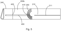
- Fig. 4 and Fig. 5 each show a schematic representation of a rotor blade tip region and a rotor blade tip of a rotor blade according to one aspect of the present invention.
- the rotor blade 200 has an air duct 210, optionally a deflection unit 250, a rotor blade tip region 220, and a rotor blade tip 240.
- At least one heat exchanger 400 is provided between the rotor blade tip 240 and a distal (second) end 210b of the air duct 210.
- the heat exchanger 400 has a first end 410 and a second end 420. The first end 410 extends to the second end 210b of the air duct and optionally into the region of the deflection unit 250.
- the second end 420 of the heat exchanger 400 is coupled to the rotor blade tip 240.
- heat is absorbed from the air duct and transferred through the heat exchanger 400 to the rotor blade tip 240 by means of heat conduction. This leads to heating of the material in the region of the rotor blade tip 240.
- the provision of the heat exchanger between the second end 210b of the air duct, which simultaneously represents the end of the air duct, and the rotor blade tip enables heating of the material in the region of the rotor blade tip without the need for an active heat exchanger. This is particularly advantageous when the volume in the area of the rotor blade tip is too small to allow effective air flow.
- the heat exchanger 400 can be designed as a rod made of a material that has good thermal conductivity, e.g., copper.
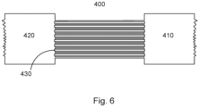
- Fig. 6 shows a schematic representation of a heat exchanger.
- the heat exchanger 400 is configured here as a heat pipe.
- the first end 410 serves as an evaporator, and the second end 420 serves as a condenser.
- the heat exchanger 400 can transfer heat from the first end 410 to the second end 420.
- Fig. 7A and 7B each show a schematic representation of a heat exchanger 400.
- the heat exchanger 400 is shown with a first and second end 410, 420.
- the heat exchanger 400 can be designed, in particular, as a rod, for example made of metal.
- a thread 411 can be provided at the first end 410.
- the thread can also be provided at the second end 420.
- the first end 410 of the heat exchanger 400 can be screwed, for example, in or onto a deflection unit 250.
- the heat exchanger 400 can also be screwed to the rotor blade tip 240 by means of a corresponding thread.
- a contact surface between the heat exchanger and the deflection unit or the rotor blade tip can be enlarged.
- FIG. 7B An alternative embodiment is provided, wherein an element 440 is coupled to or on the heat exchanger 400.
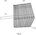
- Fig. 8 shows a further schematic representation of a heat exchanger according to one aspect of the present invention.
- the heat exchanger 400 has a first end 410 and a second end 420.
- the heat exchanger 400 can be configured, for example, in the form of a heat pipe.
- a plurality of heat transfer fins 421 can be provided at the second end 420.
- Fig. 9 shows a schematic representation of a rotor blade tip region and a rotor blade tip of a rotor blade according to one aspect of the present invention.
- the rotor blade has a rotor blade tip region 200b and a rotor blade tip 240.
- An active heating unit 500 can be provided in the rotor blade tip region 200b.
- This heating unit 500 can, for example, be an electrically operated heating unit.
- at least one heat exchanger 400 is provided.
- a first end 410 of the The heat exchanger is located in the area of the heating unit.
- the second end 420 of the heat exchanger is located in the rotor blade tip 240 or is coupled to the rotor blade tip 240.
- Fig. 10 shows a further embodiment of the rotor blade tip region and a rotor blade tip of a rotor blade according to one aspect of the present invention.
- the structure of the rotor blade of Fig. 10 essentially corresponds to the structure of the rotor blade of Fig. 9
- a rotor blade is provided with an air duct 210, a rotor blade tip region 200b, and a rotor blade tip 240.
- At least one active heating unit 500 can be provided at the second end 210b of the air duct.
- At least one, for example, several heat exchangers 400 can be provided for heat conduction.
Landscapes
- Engineering & Computer Science (AREA)
- Life Sciences & Earth Sciences (AREA)
- Sustainable Development (AREA)
- Sustainable Energy (AREA)
- Chemical & Material Sciences (AREA)
- Combustion & Propulsion (AREA)
- Mechanical Engineering (AREA)
- General Engineering & Computer Science (AREA)
- Heat-Exchange Devices With Radiators And Conduit Assemblies (AREA)
Abstract
Es wird ein Windenergieanlagen-Rotorblatt (200) vorgesehen, das einen Rotorblattwurzelbereich (200a), einen Rotorblattspitzenbereich (200b), eine Rotorblattspitze (240), eine Druckseite (200c), eine Saugseite (200d), eine Luftführung (210) für erwärmte Luft mit einem ersten Ende (210a) an dem Rotorblattwurzelbereich (200b) und einem zweiten Ende (210b) an dem Rotorblattspitzenbereich (200b), und mindestens einen Wärmeübertrager (400) zwischen dem zweiten Ende (210b) der Luftführung (210) und dem Rotorblattspitzenbereich (200b) oder der Rotorblattspitze (240) aufweist.
Description
- Die vorliegende Erfindung betrifft ein Windenergieanlagen-Rotorblatt sowie eine Windenergieanlage mit einem entsprechenden Rotorblatt.
- Da die Rotorblätter einer Windenergieanlage ungeschützt allen Witterungsbedingungen ausgesetzt sind, kann es bei bestimmten Temperaturen zu einer Vereisung der Rotorblätter kommen. Um dies zu verhindern, kann eine Rotorblattheizung verwendet werden. Hierbei kann entweder eine Heizung außen am Rotorblatt vorgesehen werden oder erwärmte Luft kann innerhalb des Rotorblattes vorgesehen sein.
-
WO 2017/021350 A1 zeigt ein Windenergieanlagen-Rotorblatt mit einem Rotorblattwurzelbereich und einem Rotorblattspitzenbereich sowie einer Rotorblattheizung. Ferner ist mindestens ein Steg entlang einer Längsrichtung des Rotorblattes vorgesehen. An dem Steg kann eine Umlenkeinheit in Form eines Stegtropfens vorgesehen sein, um eine Verwirbelung der Luft beim Umlenken zu reduzieren. -
WO 2018/211055 zeigt ein Rotorblatt einer Windenergieanlage einer Rotorblattheizung mit einem Rotorblatt, welches einen Steg und eine Umlenkeinheit an der Rotorblattspitze zum Umlenken von erwärmter Luft aufweist. - Es ist eine Aufgabe der vorliegenden Erfindung, ein Windenergieanlagen-Rotorblatt vorzusehen, welches eine verbesserte Beheizung des Rotorblattes, insbesondere eine verbesserte Beheizung der Rotorblattspitze, ermöglicht.
- Diese Aufgabe wird durch ein Windenergieanlagen-Rotorblatt nach Anspruch 1 gelöst.
- Somit wird ein Windenergieanlagen-Rotorblatt mit einem Rotorblattwurzelbereich, einem Rotorblattspitzenbereich, einer Druckseite, einer Saugseite, einer Vorderkante, einer Hinterkante vorgesehen. Ferner ist eine Luftführung für erwärmte Luft innerhalb des Rotorblattes vorgesehen. Die Luftführung dient dazu, erwärmte Luft, welche beispielsweise mittels einer Rotorblattheizung erzeugt worden ist, in das Innere des Rotorblattes zu leiten, um die Temperatur des Materials des Rotorblattes soweit anzuheben, dass ein Eisansatz reduziert oder vermieden wird. Das Rotorblatt wird somit mittels der erwärmten Luft beheizt. Die Luftführung weist ein erstes Ende im Rotorblattwurzelbereich und ein zweites Ende im Rotorblattspitzenbereich auf.
- Zwischen dem zweiten Ende der Luftführung und dem Rotorblattspitzenbereich ist mindestens ein Wärmeübertrager vorgesehen, um Wärme aus dem Bereich der Luftführung zu dem Rotorblattspitzenbereich zu übertragen.
- Optional ist der Wärmeübertrager passiv ausgestaltet, d. h. Wärme wird ohne Energiezufuhr (z. B. in Form einer elektrischen Beheizung) von außen übertragen. Optional kann der Wärmeübertrager als ein Wärmerohr (Heatpipe), als Zwei-Phasen-Thermosyphon und/oder als Wärmebrücke ausgestaltet sein.
- Der Wärmeübertrager kann optional auch als mindestens ein Stab mit einem wärmeleitenden Material (z. B. Metall) ausgestaltet sein.
- Eine Wärmeübertragung in dem Wärmeübertrager erfolgt durch Wärmeleitung (Wärmediffusion oder Konduktion). Eine Wärmeübertragung in der Luftführung hingegen erfolgt durch Konvektion. Der Wärmeübertrager ist somit ein Wärmeleitungs-Wärmeübertrager.
- Gemäß einem Aspekt der vorliegenden Erfindung weist die Luftführung mindestens einen Steg auf, welcher zwischen der Druckseite und der Saugseite und entlang einer Längsrichtung des Rotorblattes sich erstreckt.
- Optional kann eine Umlenkeinheit (mit mindestens einem Umlenkbogen) zwischen einem Ende des mindestens einen Stegs und z. B. dem Rotorblattspitzenbereich oder einem weiteren Steg vorgesehen und dazu ausgestaltet sein, erwärmte Luft, welche von dem Rotorblattwurzelbereich entlang des mindestens einen Stegs strömt, umzulenken.
- Gemäß einem Aspekt der vorliegenden Erfindung ist der mindestens eine Wärmeübertrager in einem Bereich zwischen der Umlenkeinheit und einem Rotorblattspitzenbereich vorgesehen. Somit kann Wärme am distalen Ende der Stege mittels des Wärmeübertragers weiter zu dem Rotorblattspitzenbereich geleitet werden. Hierbei kann die Wärmeleitung nicht durch Wärmeströmung, sondern innerhalb des Wärmeübertragers erfolgen. Dies ist insbesondere vorteilhaft, wenn in dem Rotorblattspitzenbereich nicht ausreichend Volumen vorhanden ist, um eine effektive Luftströmung für die Lufterwärmung zu erreichen.
- Die Ausgestaltung des Wärmeübertragers als passiver Wärmeübertrager ist vorteilhaft, weil damit für die Wärmeübertragung ein reduzierter Querschnitt benötigt wird. Gemäß einem Aspekt der vorliegenden Erfindung erstreckt sich der mindestens eine Wärmeübertrager zwischen einer Umlenkeinheit am Ende der Stege und dem Rotorblattspitzenbereich.
- Gemäß einem weiteren Aspekt der vorliegenden Erfindung ist der Wärmeübertrager als eine Heatpipe oder ein Wärmerohr ausgestaltet, welche(s) an einem Ende ein Gewinde aufweist. Mittels des Gewindes kann die Heatpipe im Bereich der Umlenkeinheit und im Bereich der Rotorblattspitze verschraubt werden, so dass eine Oberfläche erhöht werden kann, welche zur Wärmeübertragung genutzt werden kann.
- Ein Wärmerohr bzw. eine Heatpipe ist ein Wärmeübertrager, der unter Nutzung der Verdampfungsenthalpie eines Mediums eine hohe Wärmestromdichte erlaubt. Somit können große Wärmemengen auf kleiner Querschnittsfläche übertragen werden. Ein Wärmerohr kann als eine Heatpipe oder als ein 2-Phasen-Thermosyphon ausgestaltet sein. Die Fähigkeit, Energie zu transportieren, hängt bei dem Wärmerohr bzw. der Heatpipe von der spezifischen Verdampfungsenthalpie des Arbeitsmediums ab.
- Gemäß einem Aspekt der Erfindung kann der Wärmeübertrager als ein Stab aus einem Vollmaterial mit guter Wärmeleitfähigkeit (z. B. Kupfer) ausgestaltet sein.
- Dies ist vorteilhaft, da ein derartiger Stab nicht durch Fliehkräfte beeinflusst wird, welche beim Betrieb der Windenergieanlage in den Rotorblättern auftreten können.
- Gemäß einem weiteren Aspekt der vorliegenden Erfindung wird ein Windenergieanlagen-Rotorblatt vorgesehen, welches eine elektrische Heizeinheit im Bereich des Rotorblattspitzenbereichs aufweist. Zwischen der Heizmatte und dem Rotorblattspitzenbereich ist mindestens ein Wärmeübertrager vorgesehen, um Wärme von der Heizeinheit an den Rotorblattspitzenbereich zu übertragen.
- Gemäß einem Aspekt der vorliegenden Erfindung ist der Rotorblattspitzenbereich oder zumindest ein Abschnitt davon abnehmbar ausgestaltet.
- Gemäß einem weiteren Aspekt der vorliegenden Erfindung weist die Luftführung eine Abzweigung auf. Eine erfindungsgemäße Umlenkeinheit ist an der Abzweigung vorgesehen und dient der Reduzierung der Druckverluste im Bereich der Abzweigung.
- Gemäß der Erfindung kann ein Strömungshindernis in der Luftführung eine Abzweigung der Luftführung oder ein Ende des Bereichs der Luftführung (z. B. ein Ende des Steges) darstellen, wo ein Umlenken der Luftströmung benötigt wird.
- Ferner betrifft die Erfindung eine Windenergieanlage mit mindestens einem oben beschriebenen Windenergieanlagen-Rotorblatt und einer Rotorblatt-Heizung.
- Gemäß einem Aspekt der vorliegenden Erfindung kann warme bzw. erwärmte Luft (welche durch die Rotorblattheizung erzeugt wird) zur Beheizung des Rotorblattes in den Rotorblattwurzelbereich eingeführt bzw. eingeströmt werden. Die erwärmte Luft kann dann durch eine Luftführung entlang der Länge des Rotorblattes strömen. Die Luftführung kann in dem Bereich zwischen der Vorderkante und einem ersten Steg vorgesehen sein, so dass die erwärmte Luft entlang der Vorderkante und des Steges vom Rotorblattwurzelbereich in Richtung des Rotorblattspitzenbereichs strömt. Alternativ dazu kann die erwärmte Luft in den Bereich zwischen der Hinterkante und dem anderen Steg von dem Wurzelblattwurzelbereich zum Rotorblattspitzenbereich strömen. An einem der Stege ist eine Umlenkeinheit mit mindestens zwei Umlenkbögen vorgesehen. Zur weiteren Erwärmung auch der Rotorblattspitze wird ein Wärmeübertrager (durch Wärmeleitung) zwischen dem Ende der Luftführung und der Rotorblattspitze vorgesehen.
- Somit wird ein Windenergieanlagen-Rotorblatt mit einem Rotorblattwurzelbereich, einem Rotorblattspitzenbereich, einer Druckseite, einer Saugseite und mindestens einem Steg vorgesehen, welcher sich entlang einer Längsrichtung des Rotorblattes erstreckt. Die Rotorblattspitze kann zwar hohl ausgestaltet sein, aber mit einem Füllmaterial ausgeschäumt sein. Damit wird eine effektive Beheizung einer Rotorblattspitze behindert. Dies kann zu einem Eisansatz insbesondere im Bereich der Rotorblattspitze und kann aufgrund der hohen Geschwindigkeit der Rotorblattspitze zu einem gefährlichen Eisabwurf führen.
- Zur weiteren Verbesserung kann eine Bypass-Hutze in oder an einem der Stege vorgesehen werden, welche die Strömung im Umlenkbereich optimiert, in dem die Grenzschichtströmung am Stegende abgesaugt wird und somit Strömungsabrisse und Verwirbelungen vermindert werden können.
- Gemäß der Erfindung wird ein Windenergieanlagen-Rotorblatt vorgesehen, welches mindestens ein, vorzugsweise zwei, Stege entlang der Längsrichtung des Rotorblattes aufweist. Zur Beheizung des Rotorblattes kann eine Luftströmung entlang der Stege vorgesehen sein. Die Luftströmung startet im Rotorblattwurzelbereich und die, vorzugsweise erwärmte, Luft strömt entlang des ersten und/oder zweiten Steges und muss umgelenkt werden. Dies erfolgt durch eine Umlenkeinheit mit mindestens einem Umlenkbogen.
- Die Umlenkeinheit kann mindestens einen (insbesondere zwei oder drei) Umlenkbögen aufweisen. Die Umlenkbögen können in Längsrichtung beabstandet mit der offenen Seite zur Rotorblattwurzel angeordnet sein.
- Weitere Ausgestaltungen der Erfindung sind Gegenstand der Unteransprüche.
- Vorteile und Ausführungsbeispiele der Erfindung werden nachstehend unter Bezugnahme auf die Zeichnung näher erläutert.
- Fig. 1
- zeigt eine schematische Darstellung einer Windenergieanlage gemäß der Erfindung,
- Fig. 2
- zeigt eine schematische und abschnittsweise Darstellung eines Rotorblattes der Windenergieanlage von
Fig. 1 , - Fig. 3
- zeigt eine schematische Darstellung eines Abschnitts eines Rotorblattes gemäß der Erfindung,
- Fig. 4 und 5
- zeigen jeweils eine schematische Darstellung eines Rotorblattspitzenbereichs und einer Rotorblattspitze eines Rotorblattes gemäß einem Aspekt der vorliegenden Erfindung,
- Fig. 6
- zeigt eine schematische Darstellung eines Wärmeübertragers,
- Fig. 7A und 7B
- zeigen jeweils eine schematische Darstellung eines Wärmeübertragers gemäß einem Aspekt der Erfindung,
- Fig. 8
- zeigt ebenfalls eine schematische Darstellung eines Wärmeübertragers,
- Fig. 9
- zeigt eine schematische Darstellung eines Rotorblattspitzenbereichs und einer Rotorblattspitze gemäß einem Aspekt der vorliegenden Erfindung, und
- Fig. 10
- zeigt eine schematische Darstellung eines Rotorblattspitzenbereichs und einer Rotorblattspitze gemäß einem Aspekt der vorliegenden Erfindung.
-
Fig. 1 zeigt eine schematische Darstellung einer Windenergieanlage gemäß der Erfindung. Die Windenergieanlage 100 weist einen Turm 102 und eine Gondel 104 auf dem Turm 102 auf. An der Gondel 104 ist ein aerodynamischer Rotor 106 mit drei Rotorblättern 200 und einem Spinner 110 vorgesehen. Der aerodynamische Rotor 106 wird im Betrieb der Windenergieanlage durch den Wind in eine Drehbewegung versetzt und dreht somit auch einen Rotor oder Läufer eines Generators, welcher direkt oder indirekt mit dem aerodynamischen Rotor 106 gekoppelt ist. Der elektrische Generator ist in der Gondel 104 angeordnet und erzeugt elektrische Energie. Die Pitchwinkel der Rotorblätter 200 können durch Pitchmotoren an den Rotorblattwurzeln der jeweiligen Rotorblätter 200 verändert werden. -
Fig. 2 zeigt eine schematische und abschnittsweise Darstellung eines Rotorblattes der Windenergieanlage vonFig. 1 . Das Rotorblatt 200 weist einen Rotorblattwurzelbereich 200a, einen Rotorblattspitzenbereich 200b, eine Rotorblattspitze 240, eine Vorderkante 201, eine Hinterkante 202, eine Druckseite 200c und eine Saugseite 200d auf. Innerhalb des Rotorblattes 200 ist eine Luftführung vorgesehen, die mindestens ein Strömungshindernis aufweist. Eine Rotorblattheizung 300 kann im Bereich des Rotorblattwurzelbereichs 200 vorgesehen sein. Die Rotorblattheizung 300 weist mindestens einen Luftfilter auf und erzeugt warme Luft, die in das Innere des Rotorblattes geleitet wird. - Entlang einer Längsrichtung L des Rotorblattes 200 erstreckt sich innerhalb des Rotorblattes mindestens ein Steg 210, der Teil der Luftführung ist bzw. der aus anderen Gründen bereits vorhanden ist und die Luftführung lediglich eine sekundäre Funktion ist. Beispielsweise können zwei Stege 211, 212 vorgesehen sein, welche zunächst parallel und optional im Bereich der Rotorblattspitze 240 aufeinander zulaufend ausgestaltet sein können. Hierbei kann die Länge des ersten Steges 211 geringer sein als die Länge des zweiten Steges 212. Die Rotorblattspitze 240 kann optional als ein separates Teil ausgestaltet sein und an dem Rest des Rotorblattes 200 befestigt werden.
- Durch die Rotorblattheizung erwärmte Luft kann entlang der Stege - als Teil der Luftführung - in Richtung der Rotorblattspitze 240 geführt und dann umgelenkt werden. Optional kann die Rotorblattspitze 240 zumindest teilweise hohl ausgestaltet sein, so dass ein Teil der erwärmten Luft durch die Rotorblattspitze 240 strömen kann, um die Rotorblattspitze 240 zu enteisen.
- Gemäß einem Aspekt der vorliegenden Erfindung kann die erwärmte Luft mittels der Rotorblattheizung 300 entweder im Rotorblattwurzelbereich erzeugt werden, in dem Luft mittels einer Heizeinheit 300 erwärmt wird oder die erwärmte Luft wird dem Rotorblatt 200 in dem Rotorblattwurzelbereich 200a zugeführt.
- Gemäß einem Aspekt der vorliegenden Erfindung kann die Luftführung eine Abzweigung aufweisen, um beispielsweise verschiedene Abschnitte innerhalb des Rotorblattes mit erwärmter Luft versorgen zu können. Im Bereich der Abzweigung ist eine erfindungsgemäße Umlenkeinheit 250 mit mindestens zwei Umlenkbögen vorgesehen, so dass erwärmte Luft, welche mittels der Abzweigung abgezweigt werden soll, auch durch die Umlenkeinheit strömt und damit umgelenkt wird.
-
Fig. 3 zeigt eine schematische Darstellung eines Abschnitts eines Rotorblattes gemäß der Erfindung. Das Rotorblatt 200 weist zwei Stege 211, 212 auf, welche beispielsweise wie inFig. 2 gezeigt verlaufen können. An dem ersten Steg 211 oder alternativ an dem zweiten Steg 212 ist eine Umlenkeinheit 250 vorgesehen. Die Umlenkeinheit 250 soll dazu dienen, erwärmte Luft, welche zwischen einer Vorderkante und dem ersten Steg 211, zwischen dem ersten und zweiten Steg 211, 212 oder zwischen dem zweiten Steg 212 und der Hinterkante von der Rotorblattwurzel Richtung Rotorblattspitze strömt, umzulenken. Die erwärmte Luft kann durch die Rotorblattheizung 300 im Bereich der Rotorblattwurzel erzeugt werden. - Die Umlenkeinheit 250 kann einen Umlenkbogen, insbesondere zwei Umlenkbögen 251, 252, aufweisen. Hierbei kann der erste Umlenkbogen 251 einen größeren Radius aufweisen als der zweite Umlenkbogen 252. Zwischen einem Ende 211a des ersten Steges 211 und dem zweiten Umlenkbogen 252 ist ein Freiraum vorgesehen, so dass warme Luft durch den zweiten Umlenkbogen 252 umgelenkt werden kann. In einem Abstand zum zweiten Umlenkbogen 252 ist der erste Umlenkbogen 251 vorgesehen, der einen größeren Radius aufweist als der zweite Umlenkbogen 252. Das erste Ende des Umlenkbogens ragt in einen Bereich zwischen der Vorderkante 201 und dem ersten Steg 211. Das zweite Ende ragt in den Bereich zwischen dem ersten und zweiten Steg 211, 212. Optional kann das erste Ende des ersten Umlenkbogens 251 eine Verlängerung aufweisen, so dass das erste Ende des ersten Umlenkbogens 251 an eine Wandung der Vorderkante 201 zumindest teilweise angrenzt. Der zweite Umlenkbogen 252 weist ein erstes und zweites Ende und einen Bogenabschnitt 252b dazwischen auf.
- In
Fig. 3 ist ein Abschnitt des Rotorblattes 200 mit einer Umlenkeinheit 250 gemäß der Erfindung dargestellt, welche einen ersten und zweiten Umlenkbogen 251, 252 aufweist. Erwärmte Luft 10 kann entlang des ersten Steges 211 strömen und trifft auf die Umlenkeinheit 250, wo sie in einen Bereich zwischen dem ersten und zweiten Steg 211, 212 umgelenkt werden kann. Hierbei entsteht jedoch ein Totluftgebiet 11 am Ende des Steges 211. - Die Umlenkeinheit 250 mit mindestens einem Umlenkbogen 251, 252 bewirkt eine erhebliche Reduzierung des Totluftgebietes 11. Dies führt zu einer Reduzierung des Druckverlustes durch die Umlenkeinheit. Damit kann die Beheizung des Rotorblattes 200 erheblich verbessert werden.
-
Fig. 4 undFig. 5 zeigen jeweils eine schematische Darstellung eines Rotorblattspitzenbereichs und einer Rotorblattspitze eines Rotorblattes gemäß einem Aspekt der vorliegenden Erfindung. Das Rotorblatt 200 weist eine Luftführung 210, optional eine Umlenkeinheit 250, einen Rotorblattspitzenbereich 220 und eine Rotorblattspitze 240 auf. Zwischen der Rotorblattspitze 240 und einem distalen (zweiten) Ende 210b der Luftführung 210 ist mindestens ein Wärmeübertrager 400 vorgesehen. Der Wärmeübertrager 400 weist ein erstes Ende 410 und ein zweites Ende 420 auf. Das erste Ende 410 erstreckt sich zu dem zweiten Ende 210b der Luftführung und optional in den Bereich der Umlenkeinheit 250 hinein. Das zweite Ende 420 des Wärmeübertragers 400 ist mit der Rotorblattspitze 240 gekoppelt. An dem ersten Ende 410 des Wärmeübertragers 400 wird Wärme von der Luftführung aufgenommen und durch den Wärmeübertrager 400 zu der Rotorblattspitze 240 mittels Wärmeleitung übertragen. Dies führt zu einer Erwärmung des Materials im Bereich der Rotorblattspitze 240. Das Vorsehen des Wärmeübertragers zwischen dem zweiten Ende 210b der Luftführung, welches gleichzeitig das Ende der Luftführung darstellt, und der Rotorblattspitze ermöglicht eine Erwärmung des Materials im Bereich der Rotorblattspitze, ohne dass dazu ein aktiver Wärmeübertrager benötigt wird. Dies ist insbesondere vorteilhaft, wenn das Volumen im Bereich der Rotorblattspitze zu klein ist, um eine effektive Luftströmung zu ermöglichen. - Der Wärmeübertrager 400 kann als Stab mit einem Material ausgestaltet sein, das über eine gute Wärmeleitfähigkeit verfügt, z. B. Kupfer.
-
Fig. 6 zeigt eine schematische Darstellung eines Wärmeübertragers. Der Wärmeübertrager 400 ist hier als eine Heatpipe ausgestaltet. Das erste Ende 410 dient als Verdampfer und das zweite Ende 420 dient als Kondensator. Somit kann der Wärmeübertrager 400 Wärme von dem ersten Ende 410 zu dem zweiten Ende 420 übertragen. -
Fig. 7A und 7B zeigen jeweils eine schematische Darstellung eines Wärmeübertragers 400. InFig. 7A ist der Wärmeübertrager 400 mit einem ersten und zweiten Ende 410, 420 dargestellt. Der Wärmeübertrager 400 kann insbesondere als ein Stab beispielsweise aus Metall ausgestaltet sein. An dem ersten Ende 410 kann ein Gewinde 411 vorgesehen sein. Das Gewinde kann auch alternativ dazu an dem zweiten Ende 420 vorgesehen sein. Mittels des Gewindes 411 kann das erste Ende 410 des Wärmeübertragers 400 zum Beispiel in oder an einer Umlenkeinheit 250 verschraubt sein. Alternativ dazu kann der Wärmeübertrager 400 auch mittels eines entsprechenden Gewindes an der Rotorblattspitze 240 verschraubt sein. Durch das Vorsehen des Gewindes kann eine Kontaktoberfläche zwischen dem Wärmeübertrager und der Umlenkeinheit oder der Rotorblattspitze vergrößert werden. - In
Fig. 7B ist eine alternative Ausgestaltung vorgesehen, wobei ein Element 440 mit bzw. an dem Wärmeübertrager 400 gekoppelt ist. -
Fig. 8 zeigt eine weitere schematische Darstellung eines Wärmeübertragers gemäß einem Aspekt der vorliegenden Erfindung. Der Wärmeübertrager 400 weist ein erstes Ende 410 und ein zweites Ende 420 auf. Der Wärmeübertrager 400 kann beispielsweise in Form einer Heatpipe ausgestaltet sein. An dem zweiten Ende 420 kann eine Mehrzahl von Wärmeübertragungsrippen 421 vorgesehen sein. -
Fig. 9 zeigt eine schematische Darstellung eines Rotorblattspitzenbereichs sowie einer Rotorblattspitze eines Rotorblatts gemäß einem Aspekt der vorliegenden Erfindung. Das Rotorblatt weist einen Rotorblattspitzenbereich 200b sowie eine Rotorblattspitze 240 auf. In dem Rotorblattspitzenbereich 200b kann eine aktive Heizeinheit 500 vorgesehen sein. Diese Heizeinheit 500 kann beispielsweise eine elektrisch betriebene Heizeinheit darstellen. Ferner ist mindestens ein Wärmeübertrager 400 vorgesehen. Ein erstes Ende 410 des Wärmeübertragers befindet sich im Bereich der Heizeinheit. Das zweite Ende 420 des Wärmeübertragers befindet sich in der Rotorblattspitze 240 oder ist mit der Rotorblattspitze 240 gekoppelt. -
Fig. 10 zeigt eine weitere Ausgestaltung des Rotorblattspitzenbereichs und einer Rotorblattspitze eines Rotorblattes gemäß einem Aspekt der vorliegenden Erfindung. Der Aufbau des Rotorblattes vonFig. 10 entspricht im Wesentlichen dem Aufbau des Rotorblattes vonFig. 9 . Somit ist ein Rotorblatt mit einer Luftführung 210, einem Rotorblattspitzenbereich 200b und einer Rotorblattspitze 240 vorgesehen. An dem zweiten Ende 210b der Luftführung kann mindestens eine aktive Heizeinheit 500 vorgesehen sein. Zwischen der Heizeinheit 500 und der Rotorblattspitze 240 kann mindestens ein, beispielsweise auch mehrere Wärmeübertrager 400 zur Wärmeleitung vorgesehen sein.
Claims (11)
- Windenergieanlagen-Rotorblatt (200), miteinem Rotorblattwurzelbereich (200a),einem Rotorblattspitzenbereich (200b),einer Rotorblattspitze (240),einer Druckseite (200c),einer Saugseite (200d),einer Luftführung (210) für erwärmte Luft mit einem ersten Ende (210a) an dem Rotorblattwurzelbereich (200b) und einem zweiten Ende (210b) an dem Rotorblattspitzenbereich (200b), undmindestens einem Wärmeübertrager (400) zwischen dem zweiten Ende (210b) der Luftführung (210) und dem Rotorblattspitzenbereich (200b) oder der Rotorblattspitze (240).
- Windenergieanlagen-Rotorblatt (200) nach Anspruch 1, wobeidie Luftführung (210) mindestens einen Steg (210, 211, 212) aufweist, welcher zwischen der Druckseite (200c) und der Saugseite (200d) angeordnet ist und entlang einer Längsrichtung (L) des Rotorblattes (200) erstreckt,wobei der mindestens eine Wärmeübertrager (400) zwischen einem Ende des Stegs (211) und der Rotorblattspitze (240) vorgesehen ist.
- Windenergieanlagen-Rotorblatt (200) nach einem der Ansprüche 1 oder 2, wobei der Wärmeübertrager (400) als ein Wärmeleitungs-Wärmeübertrager (400) ausgestaltet ist.
- Windenergieanlagen-Rotorblatt (200) nach einem der Ansprüche 1 bis 3, ferner mit einem Umlenkbereich (250) zwischen einem Ende des mindestens einen Stegs (210, 211, 212) und dem Rotorblattspitzenbereich (200b), welcher dazu ausgestaltet ist, Luft, welche von dem Rotorblattwurzelbereich (200a) entlang des mindestens einen Stegs (210-212) strömt, umzulenken.
- Windenergieanlagen-Rotorblatt (200) nach einem der Ansprüche 1 bis 4, wobei
der Wärmeübertrager (400) als ein passiver Wärmeübertrager ausgestaltet ist und Wärme ohne Energiezufuhr von außen überträgt. - Windenergieanlagen-Rotorblatt (200) nach einem der Ansprüche 1 bis 5, wobei
der Wärmeübertrager (400) als eine Heatpipe mit einem ersten und zweiten Ende (410, 420) ausgestaltet ist, - Windenergieanlagen-Rotorblatt (200) nach Anspruch 6, wobei
das erste und/oder das zweite Ende (410, 420) des Wärmeübertragers (400) ein Gewinde zur Vergrößerung einer Kontaktfläche aufweist. - Windenergieanlagen-Rotorblatt (200) nach einem der Ansprüche 1 bis 5, wobei
der Wärmeübertrager (400) als Wärmeleitungs-Stab aus einem gut wärmeleitenden Material ausgestaltet ist. - Windenergieanlagen-Rotorblatt (200) nach einem der Ansprüche 1 bis 8, ferner mitmindestens einer aktiven Heizeinheit (500) im Rotorblattspitzenbereich (200b), wobeidie ersten Enden (410) des mindestens einen Wärmeübertragers (400) im Bereich der aktiven Heizeinheit (500) vorgesehen sind und die zweiten Enden (420) des mindestens einen Wärmeübertragers (400) in oder an der Rotorblattspitze (240) vorgesehen sind.
- Windenergieanlagen-Rotorblatt (200) nach einem der Ansprüche 1 bis 9, wobei
die Luftführung (210) eine Abzweigung und eine Umlenkeinheit (250) an der Abzweigung aufweist. - Windenergieanlage (100), mitmindestens einem Windenergieanlagen-Rotorblatt (200) nach einem der Ansprüche 1 bis 10, undmindestens einer Rotorblattheizung (300) zum Bereitstellen von erwärmter Luft für das Windenergieanlagen-Rotorblatt (200).
Priority Applications (1)
| Application Number | Priority Date | Filing Date | Title |
|---|---|---|---|
| EP23207726.3A EP4549732A1 (de) | 2023-11-03 | 2023-11-03 | Windenergieanlagen-rotorblatt |
Applications Claiming Priority (1)
| Application Number | Priority Date | Filing Date | Title |
|---|---|---|---|
| EP23207726.3A EP4549732A1 (de) | 2023-11-03 | 2023-11-03 | Windenergieanlagen-rotorblatt |
Publications (1)
| Publication Number | Publication Date |
|---|---|
| EP4549732A1 true EP4549732A1 (de) | 2025-05-07 |
Family
ID=88690043
Family Applications (1)
| Application Number | Title | Priority Date | Filing Date |
|---|---|---|---|
| EP23207726.3A Pending EP4549732A1 (de) | 2023-11-03 | 2023-11-03 | Windenergieanlagen-rotorblatt |
Country Status (1)
| Country | Link |
|---|---|
| EP (1) | EP4549732A1 (de) |
Citations (4)
| Publication number | Priority date | Publication date | Assignee | Title |
|---|---|---|---|---|
| DE20014238U1 (de) * | 2000-08-17 | 2001-06-07 | Wonner, Matthias, Dipl.-Ing., 70190 Stuttgart | Heizsystem zur Enteisung von Rotorblättern von Windkraftanlagen |
| WO2017021350A1 (de) | 2015-07-31 | 2017-02-09 | Wobben Properties Gmbh | Windenergieanlagen-rotorblatt |
| WO2018211055A1 (de) | 2017-05-18 | 2018-11-22 | Wobben Properties Gmbh | Windenergieanlagen-rotorblatt |
| EP3450751A1 (de) * | 2017-08-29 | 2019-03-06 | Fortum Power and Heat Oy | Rotorblatt für eine windturbine, windturbine mit einem oder mehreren rotorblättern und verfahren zur enteisung und/oder zum eisschutz eines spitzenteils des rotorblatts |
-
2023
- 2023-11-03 EP EP23207726.3A patent/EP4549732A1/de active Pending
Patent Citations (4)
| Publication number | Priority date | Publication date | Assignee | Title |
|---|---|---|---|---|
| DE20014238U1 (de) * | 2000-08-17 | 2001-06-07 | Wonner, Matthias, Dipl.-Ing., 70190 Stuttgart | Heizsystem zur Enteisung von Rotorblättern von Windkraftanlagen |
| WO2017021350A1 (de) | 2015-07-31 | 2017-02-09 | Wobben Properties Gmbh | Windenergieanlagen-rotorblatt |
| WO2018211055A1 (de) | 2017-05-18 | 2018-11-22 | Wobben Properties Gmbh | Windenergieanlagen-rotorblatt |
| EP3450751A1 (de) * | 2017-08-29 | 2019-03-06 | Fortum Power and Heat Oy | Rotorblatt für eine windturbine, windturbine mit einem oder mehreren rotorblättern und verfahren zur enteisung und/oder zum eisschutz eines spitzenteils des rotorblatts |
Similar Documents
| Publication | Publication Date | Title |
|---|---|---|
| EP3625454B1 (de) | Windenergieanlagen-rotorblatt | |
| EP3329120B1 (de) | Windenergieanlagen-rotorblatt | |
| EP3011172B1 (de) | Rotorblatt einer windenergieanlage, enteisungssystem und verfahren | |
| DE10000370A1 (de) | Windenergieanlage mit einem geschlossenen Kühlkreislauf | |
| EP1200733A1 (de) | Windenergieanlage mit einem geschlossenen kühlkreislauf | |
| DE102018122414B4 (de) | Temperiervorrichtung und Verfahren zum Temperieren eines Elektromoduls | |
| WO2016138979A1 (de) | Antriebssystem mit mindestens einem wärmerohr und verwendung desselben bei einem antriebssystem | |
| EP4306797B1 (de) | Windenergieanlagen-rotorblatt und windenergieanlage | |
| EP3963204B1 (de) | Rotor für eine windenergieanlage und windenergieanlage | |
| EP4180654B1 (de) | Windenergieanlagen-rotorblatt | |
| EP1738022B1 (de) | Beheizter zylinder | |
| EP3399183B1 (de) | Rotorblatt einer windenergieanlage | |
| EP4191053B1 (de) | Windenergieanlagen-rotorblatt | |
| EP4357605B1 (de) | Windenergieanlagen-rotorblatt und windenergieanlage | |
| EP4151856A1 (de) | Windenergieanlagen-rotorblatt | |
| EP3109465A1 (de) | Windenergieanlagenrotorblatt mit einer elektrischen heizeinrichtung | |
| EP4303436B1 (de) | Windenergieanlagen-rotorblatt und windenergieanlage | |
| EP4276300A1 (de) | Windenergieanlagen-rotorblatt und windenergieanlage | |
| EP4656870A1 (de) | Windenergieanlagen-rotorblatt | |
| DE102021207310A1 (de) | Wärmepumpe sowie Verfahren zum Betreiben einer Wärmepumpe | |
| DE102009026546B4 (de) | Sonnenkollektor | |
| EP4177561B1 (de) | Wärmeübertrager, wärmepumpe und verfahren zur forstsicherung eines wärmeübertragers | |
| EP3969740B1 (de) | Windenergieanlage und windenergieanlagen-rotorblatt | |
| EP3812677B1 (de) | Radiator zur kühlung eines transformators oder einer drosselspule | |
| EP3565970B1 (de) | Windenergieanlage und verwendung eines tropfenabscheiders in einem windenergieanlagenrotor |
Legal Events
| Date | Code | Title | Description |
|---|---|---|---|
| PUAI | Public reference made under article 153(3) epc to a published international application that has entered the european phase |
Free format text: ORIGINAL CODE: 0009012 |
|
| STAA | Information on the status of an ep patent application or granted ep patent |
Free format text: STATUS: THE APPLICATION HAS BEEN PUBLISHED |
|
| AK | Designated contracting states |
Kind code of ref document: A1 Designated state(s): AL AT BE BG CH CY CZ DE DK EE ES FI FR GB GR HR HU IE IS IT LI LT LU LV MC ME MK MT NL NO PL PT RO RS SE SI SK SM TR |
|
| STAA | Information on the status of an ep patent application or granted ep patent |
Free format text: STATUS: REQUEST FOR EXAMINATION WAS MADE |
|
| 17P | Request for examination filed |
Effective date: 20251107 |