EP4549712A1 - Leaning vehicle - Google Patents
Leaning vehicle Download PDFInfo
- Publication number
- EP4549712A1 EP4549712A1 EP24210098.0A EP24210098A EP4549712A1 EP 4549712 A1 EP4549712 A1 EP 4549712A1 EP 24210098 A EP24210098 A EP 24210098A EP 4549712 A1 EP4549712 A1 EP 4549712A1
- Authority
- EP
- European Patent Office
- Prior art keywords
- vehicle
- electrically assisted
- assisted turbocharger
- controller
- cylinder member
- Prior art date
- Legal status (The legal status is an assumption and is not a legal conclusion. Google has not performed a legal analysis and makes no representation as to the accuracy of the status listed.)
- Granted
Links
Images

Classifications
-
- F—MECHANICAL ENGINEERING; LIGHTING; HEATING; WEAPONS; BLASTING
- F02—COMBUSTION ENGINES; HOT-GAS OR COMBUSTION-PRODUCT ENGINE PLANTS
- F02B—INTERNAL-COMBUSTION PISTON ENGINES; COMBUSTION ENGINES IN GENERAL
- F02B37/00—Engines characterised by provision of pumps driven at least for part of the time by exhaust
-
- F—MECHANICAL ENGINEERING; LIGHTING; HEATING; WEAPONS; BLASTING
- F02—COMBUSTION ENGINES; HOT-GAS OR COMBUSTION-PRODUCT ENGINE PLANTS
- F02B—INTERNAL-COMBUSTION PISTON ENGINES; COMBUSTION ENGINES IN GENERAL
- F02B37/00—Engines characterised by provision of pumps driven at least for part of the time by exhaust
- F02B37/04—Engines with exhaust drive and other drive of pumps, e.g. with exhaust-driven pump and mechanically-driven second pump
- F02B37/10—Engines with exhaust drive and other drive of pumps, e.g. with exhaust-driven pump and mechanically-driven second pump at least one pump being alternatively or simultaneously driven by exhaust and other drive, e.g. by pressurised fluid from a reservoir or an engine-driven pump
-
- F—MECHANICAL ENGINEERING; LIGHTING; HEATING; WEAPONS; BLASTING
- F02—COMBUSTION ENGINES; HOT-GAS OR COMBUSTION-PRODUCT ENGINE PLANTS
- F02B—INTERNAL-COMBUSTION PISTON ENGINES; COMBUSTION ENGINES IN GENERAL
- F02B37/00—Engines characterised by provision of pumps driven at least for part of the time by exhaust
- F02B37/12—Control of the pumps
-
- F—MECHANICAL ENGINEERING; LIGHTING; HEATING; WEAPONS; BLASTING
- F02—COMBUSTION ENGINES; HOT-GAS OR COMBUSTION-PRODUCT ENGINE PLANTS
- F02B—INTERNAL-COMBUSTION PISTON ENGINES; COMBUSTION ENGINES IN GENERAL
- F02B37/00—Engines characterised by provision of pumps driven at least for part of the time by exhaust
- F02B37/12—Control of the pumps
- F02B37/14—Control of the alternation between or the operation of exhaust drive and other drive of a pump, e.g. dependent on speed
-
- F—MECHANICAL ENGINEERING; LIGHTING; HEATING; WEAPONS; BLASTING
- F02—COMBUSTION ENGINES; HOT-GAS OR COMBUSTION-PRODUCT ENGINE PLANTS
- F02B—INTERNAL-COMBUSTION PISTON ENGINES; COMBUSTION ENGINES IN GENERAL
- F02B39/00—Component parts, details, or accessories relating to, driven charging or scavenging pumps, not provided for in groups F02B33/00 - F02B37/00
- F02B39/02—Drives of pumps; Varying pump drive gear ratio
- F02B39/08—Non-mechanical drives, e.g. fluid drives having variable gear ratio
- F02B39/10—Non-mechanical drives, e.g. fluid drives having variable gear ratio electric
-
- Y—GENERAL TAGGING OF NEW TECHNOLOGICAL DEVELOPMENTS; GENERAL TAGGING OF CROSS-SECTIONAL TECHNOLOGIES SPANNING OVER SEVERAL SECTIONS OF THE IPC; TECHNICAL SUBJECTS COVERED BY FORMER USPC CROSS-REFERENCE ART COLLECTIONS [XRACs] AND DIGESTS
- Y02—TECHNOLOGIES OR APPLICATIONS FOR MITIGATION OR ADAPTATION AGAINST CLIMATE CHANGE
- Y02T—CLIMATE CHANGE MITIGATION TECHNOLOGIES RELATED TO TRANSPORTATION
- Y02T10/00—Road transport of goods or passengers
- Y02T10/10—Internal combustion engine [ICE] based vehicles
- Y02T10/12—Improving ICE efficiencies
Definitions
- the present teaching relates to a leaning vehicle on which an electrically assisted turbocharger is mounted.
- Patent Literature 1 International Publication No. 2020/217656 discloses a known motorcycle including an engine and a turbocharger.
- the turbocharger is driven by exhaust gas exhausted from the engine, and compresses intake air to supply a larger amount of air to the engine. It is therefore possible to obtain a large output and a high torque.
- Patent Literature 2 German Unexamined Patent Publication No. 102012004394 discloses a known automobile on which an engine and an electrically assisted turbocharger including an electric motor are mounted.
- the electrically assisted turbocharger drives the turbocharger by the electric motor in addition to the exhaust gas exhausted from the engine. This makes it possible not only to obtain a large output and a high torque, but also to improve the response characteristic of the engine in response to an operation of an acceleration operator.
- An electrically assisted turbocharger may be mounted on a leaning vehicle such as a motorcycle.
- An electric motor included in the electrically assisted turbocharger is driven by electric energy that a motor generator generates by rotational force of the crankshaft of the engine.
- the electrically assisted turbocharger and the motor generator are electric components driven at a high voltage. Electric components driven at a high voltage tend to be large in size.
- An electrically assisted turbocharger high voltage harness connecting the electrically assisted turbocharger, the motor generator, and at least one controller configured to control the electrically assisted turbocharger and the motor generator tends to be long because it is thick and cannot be easily bent. In this regard, when the high voltage harness is long, the resistance of the high voltage harness itself is large.
- a leaning vehicle is smaller in size than an automobile.
- the leaning vehicle is provided with, for example, members such as a coolant water pipe, a fuel pipe, and a low voltage harness.
- members such as a coolant water pipe, a fuel pipe, and a low voltage harness.
- the leaning vehicle tends to be restricted in the layout of the electrically assisted turbocharger.
- To provide a leaning vehicle on which an electrically assisted turbocharger is mounted it is required to facilitate the routing of an electrically assisted turbocharger high voltage harness, while taking into account other harnesses and pipes. Furthermore, it has been required to improve the degree of freedom in designing the position in the vehicle up-down direction of a motor generator controller that controls a relatively large motor generator.
- An object is to provide a leaning vehicle on which an electrically assisted turbocharger is mounted, which facilitates the routing of a thick electrically assisted turbocharger high voltage harness and improves the degree of freedom in designing the position of a motor generator controller in a vehicle up-down direction, while suppressing the electrically assisted turbocharger high voltage harness used at a high voltage from becoming long.
- the leaning vehicle on which an electrically assisted turbocharger is mounted includes: a vehicle body frame which leans in a vehicle rightward direction when turning right and leans in a vehicle leftward direction when turning left; an engine including a cylinder member forming at least one cylinder hole and a crankcase member accommodating a crankshaft rotating about an axial line extending in a vehicle left-right direction, the cylinder member being provided so that at least one cylinder axial line that is a central axial line of the at least one cylinder hole is in parallel to a vehicle up-down direction or intersects with the vehicle up-down direction; a motor generator which is configured to generate electric power by rotational force of the crankshaft; an electrically assisted turbocharger which includes a turbocharger and an electric motor, the turbocharger being configured to compress intake air supplied to the engine, by a compressor provided on the same rotational shaft as a turbine driven by exhaust gas exhausted from the engine, and the electric motor being configured to rotate the rotational shaft of the turbocharger by utilizing electric energy generated by the motor
- the electrically assisted turbocharger controller is provided forward of the front end face of the cylinder member in the vehicle front-rear direction so as to at least partially face the front end face of the cylinder member in the vehicle front-rear direction
- the motor generator controller is provided rearward of the rear end face of the cylinder member in the vehicle front-rear direction so as to at least partially face the rear end face of the cylinder member in the vehicle front-rear direction. Due to this, the electrically assisted turbocharger controller and the motor generator controller are provided to be separated from each other in the vehicle front-rear direction of the cylinder member.
- the part of the electrically assisted turbocharger high voltage harness which connects the electrically assisted turbocharger controller and the motor generator controller is at least partially provided in the space that is (a) above the lowermost end of the crankcase member in the vehicle up-down direction, (b) below the uppermost end of the cylinder member in the vehicle up-down direction, (c) inside the maximum width of the crankcase member in the vehicle left-right direction, and (d) outside the cylinder member in the vehicle left-right direction.
- the electrically assisted turbocharger is provided forward of the front end face of the cylinder member in the vehicle front-rear direction so as to at least partially face the front end face of the cylinder member in the vehicle front-rear direction
- the electrically assisted turbocharger controller is provided rearward of the rear end face of the cylinder member in the vehicle front-rear direction so as to at least partially face the rear end face of the cylinder member in the vehicle front-rear direction. Due to this, the electrically assisted turbocharger and the electrically assisted turbocharger controller are provided to be separated from each other in the vehicle front-rear direction of the cylinder member.
- the part of the electrically assisted turbocharger high voltage harness which connects the electrically assisted turbocharger and the electrically assisted turbocharger controller, is at least partially provided in the space that is (a) above the lowermost end of the crankcase member in the vehicle up-down direction, (b) below the uppermost end of the cylinder member in the vehicle up-down direction, (c) inside the maximum width of the crankcase member in the vehicle left-right direction, and (d) outside the cylinder member in the vehicle left-right direction.
- the leaning vehicle is arranged so that the length in the left-right direction is shorter than the length in the vehicle up-down direction and the length in the vehicle front-rear direction.
- either the part of the electrically assisted turbocharger high voltage harness which connects the motor generator controller and the electrically assisted turbocharger controller or the part of the electrically assisted turbocharger high voltage harness which connects the electrically assisted turbocharger and the electrically assisted turbocharger controller is provided by utilizing the space around the cylinder member and the crankcase member, which is formed by the difference in length in the vehicle left-right direction between the cylinder member. On this account, the total length of the electrically assisted turbocharger high voltage harness is suppressed and the resistance of the electrically assisted turbocharger high voltage harness itself is reduced.
- the electrically assisted turbocharger high voltage harness is routed along the vehicle front-rear direction by utilizing the space formed by utilizing the difference in length in the vehicle left-right direction between the cylinder member and the crankcase member, it is easy to route the electrically assisted turbocharger high voltage harness that is thick.
- the motor generator controller can be provided by utilizing the space extending in the vehicle up-down direction, which faces the rear end face of the cylinder member in the vehicle front-rear direction. On this account, the degree of freedom in designing the position of the motor generator controller in the vehicle up-down direction is high.
- the motor generator controller can be provided by utilizing the space extending in the vehicle up-down direction, which is rearward of the cylinder member in the front-rear direction, or the space extending in the vehicle up-down direction, which is as high as the crankcase member in the vehicle up-down direction.
- the degree of freedom in designing the position of the motor generator controller in the vehicle up-down direction is high.
- At least part of the motor generator controller is provided either rearward of or at the same position as the motor generator in the vehicle front-rear direction.
- the motor generator controller is provided rearward of or at the same position as the motor generator in the vehicle front-rear direction. It is therefore possible to provide a leaning vehicle on which an electrically assisted turbocharger is mounted, which improves the degree of freedom in designing the position of a motor generator controller in a vehicle up-down direction.
- An upper portion in the vehicle up-down direction of at least one cylinder axial line of the cylinder member is forward of a lower portion in the vehicle front-rear direction.
- the motor generator controller may not be provided rearward of the cylinder member.
- the electrically assisted turbocharger and the electrically assisted turbocharger controller are separated from each other, the electrically assisted turbocharger controller and the motor generator controller are integrated, when viewed in the cylinder axial direction, the electrically assisted turbocharger is provided forward of the cylinder member in the vehicle front-rear direction, and the electrically assisted turbocharger controller integrated with the motor generator controller is provided rearward of the cylinder member in the vehicle front-rear direction, and the part of the electrically assisted turbocharger high voltage harness which connects the electrically assisted turbocharger and the electrically assisted turbocharger controller is at least partially provided in the space that is (a) above the lowermost end of the crankcase member in the vehicle up-down direction, (b) below the uppermost end of the cylinder member in the vehicle up-down direction, (c) inside the maximum width of the crankcase member in the vehicle left-right direction, and (d) outside the cylinder member in the vehicle left-right direction.
- the electrically assisted turbocharger controller and the motor generator controller are integrated. Furthermore, the electrically assisted turbocharger which is separated from the electrically assisted turbocharger controller is provided forward of the cylinder member in the vehicle front-rear direction, and the electrically assisted turbocharger controller is provided rearward of the cylinder member in the vehicle front-rear direction. Due to this, the electrically assisted turbocharger and the electrically assisted turbocharger controller integrated with the motor generator controller are provided to be separated from each other in the vehicle front-rear direction of the cylinder member.
- the part of the electrically assisted turbocharger high voltage harness which connects the electrically assisted turbocharger and the electrically assisted turbocharger controller, is at least partially provided in the space that is (a) above the lowermost end of the crankcase member in the vehicle up-down direction, (b) below the uppermost end of the cylinder member in the vehicle up-down direction, (c) inside the maximum width of the crankcase member in the vehicle left-right direction, and (d) outside the cylinder member in the vehicle left-right direction.
- the leaning vehicle is arranged so that the length in the left-right direction is shorter than the length in the vehicle up-down direction and the length in the vehicle front-rear direction.
- the part of the electrically assisted turbocharger high voltage harness which connects the electrically assisted turbocharger integrated with the motor generator controller and the electrically assisted turbocharger controller, is provided by utilizing the space around the cylinder member and the crankcase member, which is formed by the difference in length in the vehicle left-right direction between the cylinder member. Furthermore, because the electrically assisted turbocharger controller and the motor generator controller are integrated, the electrically assisted turbocharger high voltage harness connecting the electrically assisted turbocharger controller and the motor generator controller is unnecessary. On this account, the total length of the electrically assisted turbocharger high voltage harness is suppressed and the resistance of the electrically assisted turbocharger high voltage harness itself is reduced.
- the electrically assisted turbocharger high voltage harness is routed along the vehicle front-rear direction by utilizing the space formed by utilizing the difference in length in the vehicle left-right direction between the cylinder member and the crankcase member, it is easy to route the electrically assisted turbocharger high voltage harness that is thick.
- the motor generator controller which is integrated with the electrically assisted turbocharger controller can be provided by utilizing the space extending in the vehicle up-down direction, which is provided rearward of the cylinder member in the vehicle front-rear direction. It is therefore possible to improve the degree of freedom in designing the position of the motor generator controller in the vehicle up-down direction.
- a vehicle up-down direction is a direction perpendicular to a horizontal plane when a leaning vehicle stands erect on the horizontal plane.
- a vehicle left-right direction is the left-right direction for the rider of the leaning vehicle.
- a vehicle front-rear direction is a direction orthogonal to the vehicle up-down direction and the vehicle left-right direction, and is a front-rear direction for the rider on the leaning vehicle.
- a vehicle forward direction is a direction in which the leaning vehicle travels straight.
- the vehicle body frame when a vehicle body frame leans in the vehicle rightward direction, the vehicle body frame leans in the vehicle rightward direction relative to the vehicle up-down direction. To put it differently, the vehicle body frame leans in such a way that an upper portion is rightward of a lower portion in the vehicle left-right direction.
- the definition of leaning of the vehicle body frame leftward in the vehicle left-right direction is similar to this.
- the engine may be a single-cylinder engine having one cylinder hole or a multi-cylinder engine having plural cylinder holes.
- the engine may be a parallel multi-cylinder engine having cylinder holes aligned in the vehicle left-right direction.
- the engine may be a V engine having a front cylinder member with at least one cylinder hole and a rear cylinder member provided rearward of the cylinder member.
- the rear cylinder member may or may not be included in a cylinder member of the present teaching.
- the cylinder member includes a cylinder head member and a cylinder body member.
- the cylinder hole forms a combustion chamber, with a piston and the cylinder head member, which are provided in the cylinder hole.
- the cylinder member forms plural cylinder holes
- the cylinder axial lines that are the central axial lines of the respective cylinder holes are in parallel to one another.
- the cylinder axial line is not a line segment existing only in a region where a cylinder hole exists, but a linear line with infinite length.
- the rotational axis of the crankshaft extends along the vehicle left-right direction.
- the rotational axis of the crankshaft may be in parallel to the vehicle left-right direction when the leaning vehicle stands erect.
- the cylinder member is provided at least partially above a crankcase member in the vehicle up-down direction.
- the maximum width in the vehicle left-right direction of the crankcase member is larger than the maximum width in the vehicle left-right direction of the cylinder member.
- a space in the vehicle left-right direction is provided inside the maximum width of the crankcase member and outside the cylinder member.
- the leaning vehicle may be, for example, a motorcycle or a motor tricycle having one or two front wheel(s).
- the leaning vehicle may or may not include an electric motor which is configured to generate a driving force transmitted to a driving wheel without the intervention of the crankshaft of the engine.
- At least one controller includes a motor generator controller and an electrically assisted turbocharger controller.
- the motor generator controller is configured to control a power generation function and a powering function of a motor generator having a power generation state and a powering function.
- the motor generator may be controlled by the motor generator controller to be in the power generation state as a generator, or to be in the powering state as a starter motor.
- the electrically assisted turbocharger controller is configured to control the torque and rotation speed of the electric motor included in the electrically assisted turbocharger.
- At least one controller includes an electrically assisted turbocharger controller and a motor generator controller.
- the motor generator and the motor generator controller may be separated from each other or may be integrated.
- the motor generator and the motor generator controller are provided on, for example, a side surface or an upper surface of the engine.
- the electrically assisted turbocharger and the electrically assisted turbocharger controller are integrated or are separated from each other.
- the electrically assisted turbocharger controller is provided at any position above or below the electrically assisted turbocharger in the vehicle up-down direction, to the left of or to the right of the electrically assisted turbocharger in the vehicle left-right direction, or in front of or behind the electrically assisted turbocharger in the vehicle front-rear direction.
- the motor generator may be provided on a crankshaft or may be provided on a shaft that is in parallel to the crankshaft, but is different from the crankshaft.
- a capacitor may be connected between the motor generator controller and the electrically assisted turbocharger controller.
- the electrically assisted turbocharger high voltage harness connects the motor generator and the electrically assisted turbocharger.
- the electrically assisted turbocharger high voltage harness includes a part connecting the motor generator controller and the electrically assisted turbocharger controller.
- the electrically assisted turbocharger high voltage harness includes a part connecting the motor generator and the motor generator controller when they are separated, and a part connecting the electrically assisted turbocharger and the electrically assisted turbocharger controller when they are separated.
- the electrically assisted turbocharger high voltage harness may have an orange exterior.
- a statement "in a vehicle side view, at least part of the electrically assisted turbocharger controller is provided forward of a front end face of the cylinder member in the vehicle front-rear direction to face the front end face of the cylinder member” indicates that the electrically assisted turbocharger controller provided forward of the front end face of the cylinder member in the vehicle front-rear direction overlaps the front end face of the cylinder member when viewed in the vehicle front-rear direction.
- the statement encompasses an arrangement in which, in the vehicle front-rear direction, the electrically assisted turbocharger controller is provided forward of the rearmost end of the front end face of the cylinder member in the vehicle front-rear direction and rearward of the frontmost end of the cylinder member.
- a statement "in a vehicle side view, at least part of the motor generator controller is provided rearward of the rear end face of the cylinder member in the vehicle front-rear direction to face the rear end face of the cylinder member” indicates that the motor generator controller provided rearward of the rear end face of the cylinder member in the vehicle front-rear direction overlaps the rear end face of the cylinder member when viewed in the vehicle front-rear direction.
- the statement encompasses an arrangement in which, in the vehicle front-rear direction, the motor generator controller is provided rearward of the frontmost end of the rear end face of the cylinder member in the vehicle front-rear direction and forward of the rearmost end of the cylinder member.
- the front end face of the cylinder member is a surface from the lower end of the cylinder body member connected to the crankcase member in the vehicle forward direction to the upper end of the cylinder head member in the vehicle forward direction, in a vehicle side view.
- the rear end face of the cylinder member is a surface from the lower end of the cylinder body member connected to the crankcase member in the vehicle rearward direction to the upper end of the cylinder head member in the vehicle rearward direction, in a vehicle side view.
- Each of the front end face and the rear end face of the cylinder member may not be a flat plane but a curved face, or may be formed by plural continuous faces.
- a statement "an upper portion in the vehicle up-down direction of at least one cylinder axial line is forward of a lower portion in the vehicle front-rear direction" indicates that, when at least one cylinder axial line is divided into an upper portion and a lower portion by a flat plane orthogonal to the vehicle up-down direction, the upper portion of the at least one cylinder axial line is forward in the vehicle front-rear direction of the lower portion of the at least one cylinder axial line.
- connection is not only direct attachment, connection, coupling, and support, but also indirect attachment, connection, coupling, and support are included.
- connected and coupled are not limited to physical or mechanical connections and couplings. They also include direct or indirect electrical connections and couplings.
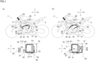
- FIGs. 1(a) and 1(b) are schematic diagram showing an example of a leaning vehicle of an embodiment of the present teaching.
- FIG. 1(a) is a schematic diagram showing a leaning vehicle of the First Embodiment.
- FIG. 1(b) is a schematic diagram showing a leaning vehicle of the Second Embodiment.
- FIGs. 2(a) and 2(b) are schematic diagram showing a modification of a leaning vehicle of an embodiment of the present teaching.
- FIG. 2(a) is a schematic diagram showing a modification of the leaning vehicle of the First Embodiment.
- FIG. 2(b) is a schematic diagram showing a modification of the leaning vehicle of the Second Embodiment.
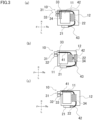
- FIGs. 3(a) and 3(b) are schematic diagram showing a modification of a leaning vehicle of an embodiment of the present teaching.
- FIG. 3(a) is a schematic representation of an engine of a leaning vehicle of a modification of the First Embodiment, which is viewed in a cylinder axial direction.
- FIG. 3(b) and FIG. 3(c) is a schematic representation of an engine of a leaning vehicle of a modification of the Second Embodiment, which is viewed in a cylinder axial direction.
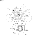
- FIG. 4 is a schematic diagram showing a modification of the leaning vehicle of the Second Embodiment of the present teaching.
- arrows F, Re, U, D, L, and R indicate a vehicle forward direction, a vehicle rearward direction, a vehicle upward direction, a vehicle downward direction, a vehicle leftward direction, and a vehicle rightward direction, respectively.
- FIG. 1(a) and FIG. 1(b) show two embodiments, respectively.
- FIG. 1 shows a leaning vehicle 1 of First Embodiment and a leaning vehicle 1 of Second Embodiment, which are in a stopped state.
- the upper figure in FIG. 1(a) is a schematic representation of a side face of the leaning vehicle 1 of First Embodiment.
- the lower figure in FIG. 1(a) is a schematic representation of an engine 10 of the leaning vehicle 1 of the First Embodiment, which is viewed in a cylinder axial direction.
- FIG. 1(b) is a schematic representation of a side face of the leaning vehicle 1 of the Second Embodiment.
- the lower figure in FIG. 1(b) is a schematic representation of an engine 10 of the leaning vehicle 1 of Second Embodiment, which is viewed in a cylinder axial direction.
- the leaning vehicle 1 includes a vehicle body frame 2.
- the vehicle body frame 2 leans in the vehicle rightward direction when turning right and leans in the vehicle leftward direction when turning left.
- the leaning vehicle 1 includes an engine 10.
- the engine 10 includes a cylinder member 11 and a crankcase member 12.
- the cylinder member 11 forms at least one unillustrated cylinder hole.
- the center line of the at least one cylinder hole is referred to as at least one cylinder axial line Cy.
- the cylinder member 11 is routed so that the at least one cylinder axial line Cy is in parallel to the vehicle up-down direction or intersects with the vehicle up-down direction.
- the crankcase member 12 includes a crankshaft 16 that is configured to rotate about an axis extending along the vehicle left-right direction.
- the at least one cylinder hole of the cylinder member 11 has at least one unillustrated combustion chamber.
- the at least one combustion chamber is connected to an intake path 17 and an exhaust path 18.
- air supplied to the at least one combustion chamber flows.
- the intake path 17 is formed by members such as an intake pipe.
- exhaust path 18 exhaust gas exhausted from the at least one combustion chamber flows.
- the exhaust path 18 is formed by members such as an exhaust pipe.
- the leaning vehicle 1 includes various unillustrated pipes and wires in addition to pipes forming parts of the intake path 17 and the exhaust path 18.
- the leaning vehicle 1 includes a motor generator 21 and a motor generator controller 22.
- the motor generator 21 is configured to be able to generate power by the rotational force of the crankshaft 16.
- the motor generator 21 is provided on the crankshaft 16.
- the motor generator 21 may be provided on a shaft that is in parallel to the crankshaft 16 and is different from the crankshaft 16, so as to be able to transmit power.
- the motor generator controller 22 is configured to control the motor generator 21.
- the motor generator controller 22 is integrated with or separated from the motor generator 21.
- the motor generator controller 22 is one of at least one controller which is configured to control the motor generator 21 and an electric motor 33 rotating a rotational shaft 32b of a later-described electrically assisted turbocharger 31.
- the leaning vehicle 1 includes an electrically assisted turbocharger 31 and an electrically assisted turbocharger controller 34.
- the electrically assisted turbocharger 31 includes a turbocharger 32 and an electric motor 33.
- the intake path 17 is formed partially inside the turbocharger 32.
- the exhaust path 18 is formed partially inside the turbocharger 32.
- the turbocharger 32 is configured to compress intake air supplied to the engine 10, by means of a compressor 32c that is provided on the same rotational shaft 32b as a turbine 32a driven by the exhaust gas exhausted from the engine 10.
- an intercooler 35 is provided to cool the air pressurized by the turbocharger 32.
- a throttle valve 36 is provided to adjust an amount of air supplied to the at least one combustion chamber.
- the electric motor 33 is configured to be able to rotate the rotational shaft 32b of the turbocharger 32 by utilizing electric energy generated by the motor generator 21.
- the electrically assisted turbocharger controller 34 is configured to control the electric motor 33 of the electrically assisted turbocharger 31.
- the electrically assisted turbocharger controller 34 is integrated with or separated from the electrically assisted turbocharger 31.
- the electrically assisted turbocharger controller 34 is one of at least one controller which is configured to control the motor generator 21 and the electric motor 33 rotating the rotational shaft 32b of the electrically assisted turbocharger 31 described later.
- the leaning vehicle 1 includes an electrically assisted turbocharger high voltage harness 40.
- the electrically assisted turbocharger high voltage harness 40 connects the motor generator 21, the electric motor 33 of the electrically assisted turbocharger 31, and the motor generator controller 22 and the electrically assisted turbocharger controller 34, which are the at least one controller.
- the electrically assisted turbocharger high voltage harness 40 supplies electric energy from the motor generator 21 to the electric motor 33 of the electrically assisted turbocharger 31.
- the electrically assisted turbocharger high voltage harness 40 includes a part 42 which connects the electrically assisted turbocharger controller 34 and the motor generator controller 22.
- the electrically assisted turbocharger high voltage harness 40 includes a part 41 which connects the electrically assisted turbocharger 31 and the electrically assisted turbocharger controller 34 when the electrically assisted turbocharger 31 and the electrically assisted turbocharger controller 34 are separated from each other. Furthermore, the electrically assisted turbocharger high voltage harness 40 includes a part 43 which connects the motor generator 21 and the motor generator controller 22 when the motor generator 21 and the motor generator controller 22 are separated from each other. In the example shown in FIG. 1 , the motor generator 21 and the motor generator controller 22 are separated from each other. In the example shown in FIG. 1 , the electrically assisted turbocharger 31 and the electrically assisted turbocharger controller 34 are separated from each other.
- the electrically assisted turbocharger high voltage harness 40 includes a part 41 which connects the electrically assisted turbocharger 31 and the electrically assisted turbocharger controller 34.
- the electrically assisted turbocharger high voltage harness 40 includes a part 42 which connects the electrically assisted turbocharger controller 34 and the motor generator controller 22.
- the electrically assisted turbocharger high voltage harness 40 includes a part 43 which connects the motor generator 21 and the motor generator controller 22.
- the motor generator 21, the motor generator controller 22, the electrically assisted turbocharger 31, the electrically assisted turbocharger controller 34, and the electrically assisted turbocharger high voltage harness 40 are arranged as in the leaning vehicle 1 of the First Embodiment shown in FIG. 1(a) or the leaning vehicle 1 of the Second Embodiment shown in FIG. 1(b) .
- the electrically assisted turbocharger controller 34 is provided forward of a front end face 11f of the cylinder member 11 in the vehicle front-rear direction so as to at least partially face the front end face 11f of the cylinder member 11 in the vehicle front-rear direction, in a vehicle side view.
- the motor generator controller 22 is provided rearward of a rear end face 11r of the cylinder member 11 in the vehicle front-rear direction so as to at least partially face the rear end face 11r of the cylinder member 11 in the vehicle front-rear direction, in the vehicle side view.
- the part 42 of the electrically assisted turbocharger high voltage harness 40 which connects the electrically assisted turbocharger controller 34 and the motor generator controller 22 is at least partially provided in a space that is (i) above the lowermost end of the crankcase member 12 in the vehicle up-down direction, (ii) below the uppermost end of the cylinder member 11 in the vehicle up-down direction, (iii) inside the maximum width of the crankcase member 12 in the vehicle left-right direction, and (iv) outside the cylinder member 11 in the vehicle left-right direction.
- the electrically assisted turbocharger 31 is provided forward of a front end face 11f of the cylinder member 11 in the vehicle front-rear direction so as to at least partially face the front end face 11f of the cylinder member 11 in the vehicle front-rear direction, in a vehicle side view. Furthermore, the electrically assisted turbocharger controller 34 is provided rearward of the rear end face 11r of the cylinder member 11 in the vehicle front-rear direction so as to at least partially face the rear end face 11r of the cylinder member 11 in the vehicle front-rear direction, in the vehicle side view. As shown in the lower figure in FIG.
- the part 41 of the electrically assisted turbocharger high voltage harness 40 which connects the electrically assisted turbocharger 31 and the electrically assisted turbocharger controller 34, is at least partially provided in a space that is (i) above the lowermost end of the crankcase member 12 in the vehicle up-down direction, (ii) below the uppermost end of the cylinder member 11 in the vehicle up-down direction, (iii) inside the maximum width of the crankcase member 12 in the vehicle left-right direction, and (iv) outside the cylinder member 11 in the vehicle left-right direction.
- At least part of the motor generator controller 22 is provided rearward of or at the same position as the motor generator 21 in the vehicle front-rear direction.
- an upper portion in the vehicle up-down direction of the at least one cylinder axial line Cy of the cylinder member 11 is forward of a lower portion in the vehicle front-rear direction.
- FIG. 2(a) is a schematic diagram showing a modification of the leaning vehicle 1 of the First Embodiment.
- the upper figure in FIG. 2(a) is a schematic representation of a side face of the leaning vehicle 1 of a modification of the First Embodiment.
- FIG. 2(a) is a schematic representation of an engine 10 of a leaning vehicle 1 of a modification of the First Embodiment, which is viewed in a cylinder axial direction.
- FIG. 2(a) shows a modification of the leaning vehicle 1 of the First Embodiment.
- the electrically assisted turbocharger controller 34 is provided forward of the front end face 11f of the cylinder member 11 in the vehicle front-rear direction so as to at least partially face the front end face 11f of the cylinder member 11 in the vehicle front-rear direction, in a vehicle side view.
- the motor generator controller 22 is provided rearward of the rear end face 11r of the cylinder member 11 in the vehicle front-rear direction so as to at least partially face the rear end face 11r of the cylinder member 11 in the vehicle front-rear direction, in the vehicle side view. As shown in the lower figure in FIG.
- the part 42 of the electrically assisted turbocharger high voltage harness 40 which connects the electrically assisted turbocharger controller 34 and the motor generator controller 22 is at least partially provided in a space that is (i) above the lowermost end of the crankcase member 12 in the vehicle up-down direction, (ii) below the uppermost end of the cylinder member 11 in the vehicle up-down direction, (iii) inside the maximum width of the crankcase member 12 in the vehicle left-right direction, and (iv) outside the cylinder member 11 in the vehicle left-right direction.
- FIG. 2(b) is a schematic diagram showing another modification of the leaning vehicle 1 of the Second Embodiment.
- the upper figure in FIG. 2(b) is a schematic representation of a side face of the leaning vehicle 1 of another modification of the Second Embodiment.
- FIG. 2(b) is a schematic representation of an engine 10 of a leaning vehicle 1 of another modification of the Second Embodiment, which is viewed in a cylinder axial direction.
- FIG. 2(b) shows a modification of the leaning vehicle 1 of the Second Embodiment.
- the electrically assisted turbocharger 31 is provided forward of the front end face 11f of the cylinder member 11 in the vehicle front-rear direction so as to at least partially face the front end face 11f of the cylinder member 11 in the vehicle front-rear direction, in a vehicle side view.
- the electrically assisted turbocharger controller 34 is provided rearward of the rear end face 11r of the cylinder member 11 in the vehicle front-rear direction so as to at least partially face the rear end face 11r of the cylinder member 11 in the vehicle front-rear direction, in the vehicle side view. As shown in the lower figure in FIG.
- the part 41 of the electrically assisted turbocharger high voltage harness 40, which connects the electrically assisted turbocharger 31 and the electrically assisted turbocharger controller 34 is at least partially provided in a space that is (i) above the lowermost end of the crankcase member 12 in the vehicle up-down direction, (ii) below the uppermost end of the cylinder member 11 in the vehicle up-down direction, (iii) inside the maximum width of the crankcase member 12 in the vehicle left-right direction, and (iv) outside the cylinder member 11 in the vehicle left-right direction.
- the motor generator controller 22 is provided at the center in the vehicle left-right direction of the leaning vehicle 1.
- the motor generator controller 22 may be provided in a vehicle left portion or a vehicle right portion.
- the electrically assisted turbocharger controller 34 is mostly provided in the vehicle left portion of the leaning vehicle 1.
- the electrically assisted turbocharger controller 34 may be mostly provided in a vehicle right portion of the leaning vehicle 1 as shown in the example in FIG. 3(a) .
- FIG. 3(a) is a schematic representation of the engine 10 of the leaning vehicle 1 of the modification of the First Embodiment shown in FIG. 1(a) , which is viewed in a cylinder axial direction.
- FIG. 3(a) is a schematic representation of the engine 10 of the leaning vehicle 1 of the modification of the First Embodiment shown in FIG. 1(a) , which is viewed in a cylinder axial direction.
- FIG. 3(b) is a schematic representation of the engine 10 of the leaning vehicle 1 of the modification of the Second Embodiment shown in FIG. 1(b) , which is viewed in a cylinder axial direction.
- FIG. 3(c) is a schematic representation of the engine 10 of the leaning vehicle 1 of the modification of the Second Embodiment shown in FIG. 1(b) , which is viewed in a cylinder axial direction.
- FIG. 4 is a schematic representation showing a modification of the leaning vehicle 1 of the Second Embodiment.
- the upper figure in FIG. 4 is a schematic representation of a side face of the leaning vehicle 1 of a modification of the Second Embodiment.
- the lower figure in FIG. 4 is a schematic representation of the engine 10 of the leaning vehicle 1 of a modification of the Second Embodiment, which is viewed in a cylinder axial direction.
- the electrically assisted turbocharger 31 and the electrically assisted turbocharger controller 34 are separated from each other. Furthermore, the motor generator 21 and the motor generator controller 22 are separated from each other. The electrically assisted turbocharger controller 34 and the motor generator controller 22 are integrated.
- the electrically assisted turbocharger 31 is provided forward of the front end face 11f of the cylinder member 11 in the vehicle front-rear direction so as to at least partially face the front end face 11f of the cylinder member 11 in the vehicle front-rear direction, in a vehicle side view.
- the electrically assisted turbocharger controller 34 integrated with the motor generator controller 22 is provided rearward of the rear end face 11r of the cylinder member 11 in the vehicle front-rear direction so as to at least partially face the rear end face 11r of the cylinder member 11 in the vehicle front-rear direction, in the vehicle side view.
- the electrically assisted turbocharger controller 34 integrated with the motor generator controller 22 is provided rearward of the rear end face 11r of the cylinder member 11 in the vehicle front-rear direction so as to at least partially face the rear end face 11r of the cylinder member 11 in the vehicle front-rear direction, in the vehicle side view.
- the part 41 of the electrically assisted turbocharger high voltage harness 40 which connects the electrically assisted turbocharger 31 and the electrically assisted turbocharger controller 34, is at least partially provided in a space that is (i) above the lowermost end of the crankcase member 12 in the vehicle up-down direction, (ii) below the uppermost end of the cylinder member 11 in the vehicle up-down direction, (iii) inside the maximum width of the crankcase member 12 in the vehicle left-right direction, and (iv) outside the cylinder member 11 in the vehicle left-right direction.
- the part 42 of the electrically assisted turbocharger high voltage harness 40 connecting the electrically assisted turbocharger controller 34 and the motor generator controller 22 may be provided to pass a position to the left of the cylinder member 11 in the vehicle left-right direction.
- the part 42 of the electrically assisted turbocharger high voltage harness 40 connecting the electrically assisted turbocharger controller 34 and the motor generator controller 22 may be provided to pass a position to the right of the cylinder member 11 in the vehicle left-right direction.
- the part 41 of the electrically assisted turbocharger high voltage harness 40 connecting the electrically assisted turbocharger 31 and the electrically assisted turbocharger controller 34 may be provided to pass a position to the left of the cylinder member 11 in the vehicle left-right direction.
- the part 41 of the electrically assisted turbocharger high voltage harness 40 connecting the electrically assisted turbocharger 31 and the electrically assisted turbocharger controller 34 may be provided to pass a position to the right of the cylinder member 11 in the vehicle left-right direction.
- the rotational shaft of the electric motor 33 of the electrically assisted turbocharger 31 is provided on a shaft that is in parallel to the rotational shaft 32b of the turbocharger 32, but is different from the rotational shaft 32b of the turbocharger 32. Furthermore, in the leaning vehicle 1 of each of the First Embodiment, Second Embodiment, and the modifications, the rotational shaft of the electric motor 33 of the electrically assisted turbocharger 31 may be provided on the rotational shaft 32b of the turbocharger 32.
Landscapes
- Engineering & Computer Science (AREA)
- Chemical & Material Sciences (AREA)
- Combustion & Propulsion (AREA)
- Mechanical Engineering (AREA)
- General Engineering & Computer Science (AREA)
- Supercharger (AREA)
Abstract
Description
- The present teaching relates to a leaning vehicle on which an electrically assisted turbocharger is mounted.
- Patent Literature 1 (International Publication No.
2020/217656 ) discloses a known motorcycle including an engine and a turbocharger. The turbocharger is driven by exhaust gas exhausted from the engine, and compresses intake air to supply a larger amount of air to the engine. It is therefore possible to obtain a large output and a high torque. - Patent Literature 2 (
German Unexamined Patent Publication No. 102012004394 ) discloses a known automobile on which an engine and an electrically assisted turbocharger including an electric motor are mounted. The electrically assisted turbocharger drives the turbocharger by the electric motor in addition to the exhaust gas exhausted from the engine. This makes it possible not only to obtain a large output and a high torque, but also to improve the response characteristic of the engine in response to an operation of an acceleration operator. - An electrically assisted turbocharger may be mounted on a leaning vehicle such as a motorcycle. An electric motor included in the electrically assisted turbocharger is driven by electric energy that a motor generator generates by rotational force of the crankshaft of the engine. The electrically assisted turbocharger and the motor generator are electric components driven at a high voltage. Electric components driven at a high voltage tend to be large in size. An electrically assisted turbocharger high voltage harness connecting the electrically assisted turbocharger, the motor generator, and at least one controller configured to control the electrically assisted turbocharger and the motor generator tends to be long because it is thick and cannot be easily bent. In this regard, when the high voltage harness is long, the resistance of the high voltage harness itself is large. A leaning vehicle is smaller in size than an automobile. The leaning vehicle is provided with, for example, members such as a coolant water pipe, a fuel pipe, and a low voltage harness. On this account, the leaning vehicle tends to be restricted in the layout of the electrically assisted turbocharger. To provide a leaning vehicle on which an electrically assisted turbocharger is mounted, it is required to facilitate the routing of an electrically assisted turbocharger high voltage harness, while taking into account other harnesses and pipes. Furthermore, it has been required to improve the degree of freedom in designing the position in the vehicle up-down direction of a motor generator controller that controls a relatively large motor generator.
- An object is to provide a leaning vehicle on which an electrically assisted turbocharger is mounted, which facilitates the routing of a thick electrically assisted turbocharger high voltage harness and improves the degree of freedom in designing the position of a motor generator controller in a vehicle up-down direction, while suppressing the electrically assisted turbocharger high voltage harness used at a high voltage from becoming long.
- The leaning vehicle on which an electrically assisted turbocharger is mounted includes: a vehicle body frame which leans in a vehicle rightward direction when turning right and leans in a vehicle leftward direction when turning left; an engine including a cylinder member forming at least one cylinder hole and a crankcase member accommodating a crankshaft rotating about an axial line extending in a vehicle left-right direction, the cylinder member being provided so that at least one cylinder axial line that is a central axial line of the at least one cylinder hole is in parallel to a vehicle up-down direction or intersects with the vehicle up-down direction; a motor generator which is configured to generate electric power by rotational force of the crankshaft; an electrically assisted turbocharger which includes a turbocharger and an electric motor, the turbocharger being configured to compress intake air supplied to the engine, by a compressor provided on the same rotational shaft as a turbine driven by exhaust gas exhausted from the engine, and the electric motor being configured to rotate the rotational shaft of the turbocharger by utilizing electric energy generated by the motor generator; at least one controller which is configured to control the motor generator and the electric motor rotating the rotational shaft of the electrically assisted turbocharger; and an electrically assisted turbocharger high voltage harness which connects the motor generator, the electric motor of the electrically assisted turbocharger, and the at least one controller so as to supply the electric energy from the motor generator to the electric motor of the electrically assisted turbocharger, the at least one controller including: a motor generator controller controlling at least the motor generator; and an electrically assisted turbocharger controller controlling the electric motor of the electrically assisted turbocharger and being integrated with or separated from the electrically assisted turbocharger, (i) in a vehicle side view, the electrically assisted turbocharger controller being provided forward of a front end face of the cylinder member in a vehicle front-rear direction so as to at least partially face the front end face of the cylinder member in the vehicle front-rear direction, and the motor generator controller being provided rearward of a rear end face of the cylinder member in the vehicle front-rear direction so as to at least partially face the rear end face of the cylinder member in the vehicle front-rear direction, and a part of the electrically assisted turbocharger high voltage harness which connects the electrically assisted turbocharger controller and the motor generator controller being at least partially provided in a space that is (a) above a lowermost end of the crankcase member in the vehicle up-down direction, (b) below an uppermost end of the cylinder member in the vehicle up-down direction, (c) inside the maximum width of the crankcase member in the vehicle left-right direction, and (d) outside the cylinder member in the vehicle left-right direction, or (ii) when viewed in the cylinder axial direction, the electrically assisted turbocharger being provided forward of the front end face of the cylinder member in the vehicle front-rear direction so as to at least partially face the front end face of the cylinder member in the vehicle front-rear direction, and the electrically assisted turbocharger controller being provided rearward of the rear end face of the cylinder member in the vehicle front-rear direction so as to at least partially face the rear end face of the cylinder member in the vehicle front-rear direction, and a part of the electrically assisted turbocharger high voltage harness which connects the electrically assisted turbocharger and the electrically assisted turbocharger controller being at least partially provided in a space that is (a) above the lowermost end of the crankcase member in the vehicle up-down direction, (b) below the uppermost end of the cylinder member in the vehicle up-down direction, (c) inside the maximum width of the crankcase member in the vehicle left-right direction, and (d) outside the cylinder member in the vehicle left-right direction.
- According to this arrangement, the electrically assisted turbocharger controller is provided forward of the front end face of the cylinder member in the vehicle front-rear direction so as to at least partially face the front end face of the cylinder member in the vehicle front-rear direction, and the motor generator controller is provided rearward of the rear end face of the cylinder member in the vehicle front-rear direction so as to at least partially face the rear end face of the cylinder member in the vehicle front-rear direction. Due to this, the electrically assisted turbocharger controller and the motor generator controller are provided to be separated from each other in the vehicle front-rear direction of the cylinder member. Furthermore, the part of the electrically assisted turbocharger high voltage harness which connects the electrically assisted turbocharger controller and the motor generator controller is at least partially provided in the space that is (a) above the lowermost end of the crankcase member in the vehicle up-down direction, (b) below the uppermost end of the cylinder member in the vehicle up-down direction, (c) inside the maximum width of the crankcase member in the vehicle left-right direction, and (d) outside the cylinder member in the vehicle left-right direction. Alternatively, the electrically assisted turbocharger is provided forward of the front end face of the cylinder member in the vehicle front-rear direction so as to at least partially face the front end face of the cylinder member in the vehicle front-rear direction, and the electrically assisted turbocharger controller is provided rearward of the rear end face of the cylinder member in the vehicle front-rear direction so as to at least partially face the rear end face of the cylinder member in the vehicle front-rear direction. Due to this, the electrically assisted turbocharger and the electrically assisted turbocharger controller are provided to be separated from each other in the vehicle front-rear direction of the cylinder member. Furthermore, the part of the electrically assisted turbocharger high voltage harness, which connects the electrically assisted turbocharger and the electrically assisted turbocharger controller, is at least partially provided in the space that is (a) above the lowermost end of the crankcase member in the vehicle up-down direction, (b) below the uppermost end of the cylinder member in the vehicle up-down direction, (c) inside the maximum width of the crankcase member in the vehicle left-right direction, and (d) outside the cylinder member in the vehicle left-right direction. The leaning vehicle is arranged so that the length in the left-right direction is shorter than the length in the vehicle up-down direction and the length in the vehicle front-rear direction. Therefore, either the part of the electrically assisted turbocharger high voltage harness which connects the motor generator controller and the electrically assisted turbocharger controller or the part of the electrically assisted turbocharger high voltage harness which connects the electrically assisted turbocharger and the electrically assisted turbocharger controller is provided by utilizing the space around the cylinder member and the crankcase member, which is formed by the difference in length in the vehicle left-right direction between the cylinder member. On this account, the total length of the electrically assisted turbocharger high voltage harness is suppressed and the resistance of the electrically assisted turbocharger high voltage harness itself is reduced. Furthermore, because the electrically assisted turbocharger high voltage harness is routed along the vehicle front-rear direction by utilizing the space formed by utilizing the difference in length in the vehicle left-right direction between the cylinder member and the crankcase member, it is easy to route the electrically assisted turbocharger high voltage harness that is thick. In the case (i), the motor generator controller can be provided by utilizing the space extending in the vehicle up-down direction, which faces the rear end face of the cylinder member in the vehicle front-rear direction. On this account, the degree of freedom in designing the position of the motor generator controller in the vehicle up-down direction is high. In the case (ii), the motor generator controller can be provided by utilizing the space extending in the vehicle up-down direction, which is rearward of the cylinder member in the front-rear direction, or the space extending in the vehicle up-down direction, which is as high as the crankcase member in the vehicle up-down direction. On this account, the degree of freedom in designing the position of the motor generator controller in the vehicle up-down direction is high.
- Because of the above, it is possible to provide a leaning vehicle on which an electrically assisted turbocharger is mounted, which facilitates the routing of a thick electrically assisted turbocharger high voltage harness and improves the degree of freedom in designing the position of a motor generator controller in a vehicle up-down direction, while suppressing the electrically assisted turbocharger high voltage harness used at a high voltage from becoming long.
- At least part of the motor generator controller is provided either rearward of or at the same position as the motor generator in the vehicle front-rear direction.
- With this arrangement, the motor generator controller is provided rearward of or at the same position as the motor generator in the vehicle front-rear direction. It is therefore possible to provide a leaning vehicle on which an electrically assisted turbocharger is mounted, which improves the degree of freedom in designing the position of a motor generator controller in a vehicle up-down direction.
- An upper portion in the vehicle up-down direction of at least one cylinder axial line of the cylinder member is forward of a lower portion in the vehicle front-rear direction.
- With this arrangement, because the cylinder member tilts in the vehicle forward direction, a space extending in the vehicle up-down direction tends to be formed rearward of the cylinder member. It is therefore possible to provide the motor generator controller by utilizing the space extending in the vehicle up-down direction and being rearward of the cylinder member, so as to improve the degree of freedom in designing the position of the motor generator controller in the vehicle up-down direction.
- It is, however, noted that, when the leaning vehicle has the above-described arrangement (3), the motor generator controller may not be provided rearward of the cylinder member.
- The electrically assisted turbocharger and the electrically assisted turbocharger controller are separated from each other, the electrically assisted turbocharger controller and the motor generator controller are integrated, when viewed in the cylinder axial direction, the electrically assisted turbocharger is provided forward of the cylinder member in the vehicle front-rear direction, and the electrically assisted turbocharger controller integrated with the motor generator controller is provided rearward of the cylinder member in the vehicle front-rear direction, and the part of the electrically assisted turbocharger high voltage harness which connects the electrically assisted turbocharger and the electrically assisted turbocharger controller is at least partially provided in the space that is (a) above the lowermost end of the crankcase member in the vehicle up-down direction, (b) below the uppermost end of the cylinder member in the vehicle up-down direction, (c) inside the maximum width of the crankcase member in the vehicle left-right direction, and (d) outside the cylinder member in the vehicle left-right direction.
- According to this arrangement, the electrically assisted turbocharger controller and the motor generator controller are integrated. Furthermore, the electrically assisted turbocharger which is separated from the electrically assisted turbocharger controller is provided forward of the cylinder member in the vehicle front-rear direction, and the electrically assisted turbocharger controller is provided rearward of the cylinder member in the vehicle front-rear direction. Due to this, the electrically assisted turbocharger and the electrically assisted turbocharger controller integrated with the motor generator controller are provided to be separated from each other in the vehicle front-rear direction of the cylinder member. Furthermore, the part of the electrically assisted turbocharger high voltage harness, which connects the electrically assisted turbocharger and the electrically assisted turbocharger controller, is at least partially provided in the space that is (a) above the lowermost end of the crankcase member in the vehicle up-down direction, (b) below the uppermost end of the cylinder member in the vehicle up-down direction, (c) inside the maximum width of the crankcase member in the vehicle left-right direction, and (d) outside the cylinder member in the vehicle left-right direction. The leaning vehicle is arranged so that the length in the left-right direction is shorter than the length in the vehicle up-down direction and the length in the vehicle front-rear direction. The part of the electrically assisted turbocharger high voltage harness, which connects the electrically assisted turbocharger integrated with the motor generator controller and the electrically assisted turbocharger controller, is provided by utilizing the space around the cylinder member and the crankcase member, which is formed by the difference in length in the vehicle left-right direction between the cylinder member. Furthermore, because the electrically assisted turbocharger controller and the motor generator controller are integrated, the electrically assisted turbocharger high voltage harness connecting the electrically assisted turbocharger controller and the motor generator controller is unnecessary. On this account, the total length of the electrically assisted turbocharger high voltage harness is suppressed and the resistance of the electrically assisted turbocharger high voltage harness itself is reduced. Furthermore, because the electrically assisted turbocharger high voltage harness is routed along the vehicle front-rear direction by utilizing the space formed by utilizing the difference in length in the vehicle left-right direction between the cylinder member and the crankcase member, it is easy to route the electrically assisted turbocharger high voltage harness that is thick. Furthermore, the motor generator controller which is integrated with the electrically assisted turbocharger controller can be provided by utilizing the space extending in the vehicle up-down direction, which is provided rearward of the cylinder member in the vehicle front-rear direction. It is therefore possible to improve the degree of freedom in designing the position of the motor generator controller in the vehicle up-down direction.
- In the present teaching and embodiments, a vehicle up-down direction is a direction perpendicular to a horizontal plane when a leaning vehicle stands erect on the horizontal plane. A vehicle left-right direction is the left-right direction for the rider of the leaning vehicle. A vehicle front-rear direction is a direction orthogonal to the vehicle up-down direction and the vehicle left-right direction, and is a front-rear direction for the rider on the leaning vehicle. A vehicle forward direction is a direction in which the leaning vehicle travels straight.
- In the present teaching and embodiments, when a vehicle body frame leans in the vehicle rightward direction, the vehicle body frame leans in the vehicle rightward direction relative to the vehicle up-down direction. To put it differently, the vehicle body frame leans in such a way that an upper portion is rightward of a lower portion in the vehicle left-right direction. The definition of leaning of the vehicle body frame leftward in the vehicle left-right direction is similar to this.
- In the present teaching and embodiments, the engine may be a single-cylinder engine having one cylinder hole or a multi-cylinder engine having plural cylinder holes. The engine may be a parallel multi-cylinder engine having cylinder holes aligned in the vehicle left-right direction. The engine may be a V engine having a front cylinder member with at least one cylinder hole and a rear cylinder member provided rearward of the cylinder member. The rear cylinder member may or may not be included in a cylinder member of the present teaching. In the present teaching and embodiments, the cylinder member includes a cylinder head member and a cylinder body member.
- In the present teaching and embodiments, the cylinder hole forms a combustion chamber, with a piston and the cylinder head member, which are provided in the cylinder hole. When the cylinder member forms plural cylinder holes, the cylinder axial lines that are the central axial lines of the respective cylinder holes are in parallel to one another.
- In the present teaching and embodiments, the cylinder axial line is not a line segment existing only in a region where a cylinder hole exists, but a linear line with infinite length.
- In the present teaching and embodiments, the rotational axis of the crankshaft extends along the vehicle left-right direction. The rotational axis of the crankshaft may be in parallel to the vehicle left-right direction when the leaning vehicle stands erect.
- In the present teaching and embodiments, the cylinder member is provided at least partially above a crankcase member in the vehicle up-down direction. In the present teaching and embodiments, the maximum width in the vehicle left-right direction of the crankcase member is larger than the maximum width in the vehicle left-right direction of the cylinder member. In other words, a space in the vehicle left-right direction is provided inside the maximum width of the crankcase member and outside the cylinder member.
- In the present teaching and embodiments, the leaning vehicle may be, for example, a motorcycle or a motor tricycle having one or two front wheel(s). In the present teaching and embodiments, the leaning vehicle may or may not include an electric motor which is configured to generate a driving force transmitted to a driving wheel without the intervention of the crankshaft of the engine.
- In the present teaching and embodiments, at least one controller includes a motor generator controller and an electrically assisted turbocharger controller. The motor generator controller is configured to control a power generation function and a powering function of a motor generator having a power generation state and a powering function. For example, the motor generator may be controlled by the motor generator controller to be in the power generation state as a generator, or to be in the powering state as a starter motor. The electrically assisted turbocharger controller is configured to control the torque and rotation speed of the electric motor included in the electrically assisted turbocharger.
- In the present teaching and embodiments, at least one controller includes an electrically assisted turbocharger controller and a motor generator controller. In the present teaching and embodiments, the motor generator and the motor generator controller may be separated from each other or may be integrated. When the motor generator and the motor generator controller are integrated, the motor generator and the motor generator controller are provided on, for example, a side surface or an upper surface of the engine. In the present teaching and embodiments, the electrically assisted turbocharger and the electrically assisted turbocharger controller are integrated or are separated from each other. When the electrically assisted turbocharger and the electrically assisted turbocharger controller are integrated, the electrically assisted turbocharger controller is provided at any position above or below the electrically assisted turbocharger in the vehicle up-down direction, to the left of or to the right of the electrically assisted turbocharger in the vehicle left-right direction, or in front of or behind the electrically assisted turbocharger in the vehicle front-rear direction. In the present teaching and embodiments, the motor generator may be provided on a crankshaft or may be provided on a shaft that is in parallel to the crankshaft, but is different from the crankshaft. In the present teaching and embodiments, a capacitor may be connected between the motor generator controller and the electrically assisted turbocharger controller. In this case, at least part of electric energy generated by the motor generator may be stored in the capacitor. In the present teaching and embodiments, the electric motor in the electrically assisted turbocharger may have a power generation function. In this case, the motor generator may be driven by utilizing at least part of electric energy generated by the electric motor in the electrically assisted turbocharger. Furthermore, when a capacitor is connected between the motor generator controller and the electrically assisted turbocharger controller, at least part of electric energy generated by the electric motor in the electrically assisted turbocharger may be stored in the capacitor.
- In the present teaching and embodiments, the electrically assisted turbocharger high voltage harness connects the motor generator and the electrically assisted turbocharger. To be more specific, the electrically assisted turbocharger high voltage harness includes a part connecting the motor generator controller and the electrically assisted turbocharger controller. Furthermore, in the present teaching and embodiments, the electrically assisted turbocharger high voltage harness includes a part connecting the motor generator and the motor generator controller when they are separated, and a part connecting the electrically assisted turbocharger and the electrically assisted turbocharger controller when they are separated. In the present embodiment, the electrically assisted turbocharger high voltage harness may have an orange exterior.
- In the present teaching and embodiments, a statement "in a vehicle side view, at least part of the electrically assisted turbocharger controller is provided forward of a front end face of the cylinder member in the vehicle front-rear direction to face the front end face of the cylinder member" indicates that the electrically assisted turbocharger controller provided forward of the front end face of the cylinder member in the vehicle front-rear direction overlaps the front end face of the cylinder member when viewed in the vehicle front-rear direction. Furthermore, the statement encompasses an arrangement in which, in the vehicle front-rear direction, the electrically assisted turbocharger controller is provided forward of the rearmost end of the front end face of the cylinder member in the vehicle front-rear direction and rearward of the frontmost end of the cylinder member. In the present teaching and embodiments, a statement "in a vehicle side view, at least part of the motor generator controller is provided rearward of the rear end face of the cylinder member in the vehicle front-rear direction to face the rear end face of the cylinder member" indicates that the motor generator controller provided rearward of the rear end face of the cylinder member in the vehicle front-rear direction overlaps the rear end face of the cylinder member when viewed in the vehicle front-rear direction. Furthermore, the statement encompasses an arrangement in which, in the vehicle front-rear direction, the motor generator controller is provided rearward of the frontmost end of the rear end face of the cylinder member in the vehicle front-rear direction and forward of the rearmost end of the cylinder member. The front end face of the cylinder member is a surface from the lower end of the cylinder body member connected to the crankcase member in the vehicle forward direction to the upper end of the cylinder head member in the vehicle forward direction, in a vehicle side view. Likewise, the rear end face of the cylinder member is a surface from the lower end of the cylinder body member connected to the crankcase member in the vehicle rearward direction to the upper end of the cylinder head member in the vehicle rearward direction, in a vehicle side view. Each of the front end face and the rear end face of the cylinder member may not be a flat plane but a curved face, or may be formed by plural continuous faces. In the present teaching and embodiments, a statement "an upper portion in the vehicle up-down direction of at least one cylinder axial line is forward of a lower portion in the vehicle front-rear direction" indicates that, when at least one cylinder axial line is divided into an upper portion and a lower portion by a flat plane orthogonal to the vehicle up-down direction, the upper portion of the at least one cylinder axial line is forward in the vehicle front-rear direction of the lower portion of the at least one cylinder axial line.
- In the present teaching and embodiments, terms "including", "comprising", "having", and derivatives thereof are used to encompass not only listed items and equivalents thereof, but also additional items.
- In the present teaching and embodiments, the terms "mounted", "connected", "coupled", and "supported" are used in broad sense. Specifically, not only direct attachment, connection, coupling, and support, but also indirect attachment, connection, coupling, and support are included. Further, connected and coupled are not limited to physical or mechanical connections and couplings. They also include direct or indirect electrical connections and couplings.
- Unless otherwise defined, all terms (technical and scientific terms) used in this description and claims indicate meanings typically understood by a person with ordinary skill in the art in the technical field to which the present teaching belongs. Terms such as those defined in commonly used dictionaries are to be interpreted as having meaning that is consistent with their meaning in the context of the relevant art and the present disclosure, and are not to be interpreted in an idealized or excessively formal sense.
- In this description, the term "may" is non-exclusive. "May be" means "may be but not limited to". In the present specification, "may" implicitly encompasses "do not".
- Before describing embodiments of the present teaching in detail, it is to be understood that the present teaching is not limited to the details of construction and arrangement of the constituent features set forth in the following description or illustrated in the drawings. The present teaching is also applicable to embodiments other than the embodiments described later. The present teaching may be implemented as embodiments with various modifications to the embodiments described below. Furthermore, the present teaching may be implemented by suitably combining below-described embodiments and modifications.
- With a leaning vehicle of the present teaching on which an electrically assisted turbocharger is mounted, it is possible to facilitate the routing of a thick electrically assisted turbocharger high voltage harness used at a high voltage and to improve the degree of freedom in designing the position of a motor generator controller in a vehicle up-down direction, while suppressing the electrically assisted turbocharger high voltage harness from becoming long.
- Each of
FIGs. 1(a) and 1(b) is a schematic diagram showing an example of a leaning vehicle of an embodiment of the present teaching.FIG. 1(a) is a schematic diagram showing a leaning vehicle of the First Embodiment.FIG. 1(b) is a schematic diagram showing a leaning vehicle of the Second Embodiment. - Each of
FIGs. 2(a) and 2(b) is a schematic diagram showing a modification of a leaning vehicle of an embodiment of the present teaching.FIG. 2(a) is a schematic diagram showing a modification of the leaning vehicle of the First Embodiment.FIG. 2(b) is a schematic diagram showing a modification of the leaning vehicle of the Second Embodiment. - Each of
FIGs. 3(a) and 3(b) is a schematic diagram showing a modification of a leaning vehicle of an embodiment of the present teaching.FIG. 3(a) is a schematic representation of an engine of a leaning vehicle of a modification of the First Embodiment, which is viewed in a cylinder axial direction. Each ofFIG. 3(b) and FIG. 3(c) is a schematic representation of an engine of a leaning vehicle of a modification of the Second Embodiment, which is viewed in a cylinder axial direction. -
FIG. 4 is a schematic diagram showing a modification of the leaning vehicle of the Second Embodiment of the present teaching. - In
FIG. 1 to FIG. 4 , arrows F, Re, U, D, L, and R indicate a vehicle forward direction, a vehicle rearward direction, a vehicle upward direction, a vehicle downward direction, a vehicle leftward direction, and a vehicle rightward direction, respectively. - The following will describe a leaning vehicle 1 of an embodiment of the present teaching with reference to
FIG. 1 to FIG. 4 . As examples of the embodiment of the leaning vehicle,FIG. 1(a) and FIG. 1(b) show two embodiments, respectively.FIG. 1 shows a leaning vehicle 1 of First Embodiment and a leaning vehicle 1 of Second Embodiment, which are in a stopped state. The upper figure inFIG. 1(a) is a schematic representation of a side face of the leaning vehicle 1 of First Embodiment. The lower figure inFIG. 1(a) is a schematic representation of anengine 10 of the leaning vehicle 1 of the First Embodiment, which is viewed in a cylinder axial direction. The upper figure inFIG. 1(b) is a schematic representation of a side face of the leaning vehicle 1 of the Second Embodiment. The lower figure inFIG. 1(b) is a schematic representation of anengine 10 of the leaning vehicle 1 of Second Embodiment, which is viewed in a cylinder axial direction. - The leaning vehicle 1 includes a
vehicle body frame 2. Thevehicle body frame 2 leans in the vehicle rightward direction when turning right and leans in the vehicle leftward direction when turning left. The leaning vehicle 1 includes anengine 10. Theengine 10 includes acylinder member 11 and acrankcase member 12. Thecylinder member 11 forms at least one unillustrated cylinder hole. The center line of the at least one cylinder hole is referred to as at least one cylinder axial line Cy. Thecylinder member 11 is routed so that the at least one cylinder axial line Cy is in parallel to the vehicle up-down direction or intersects with the vehicle up-down direction. Thecrankcase member 12 includes acrankshaft 16 that is configured to rotate about an axis extending along the vehicle left-right direction. The at least one cylinder hole of thecylinder member 11 has at least one unillustrated combustion chamber. The at least one combustion chamber is connected to anintake path 17 and anexhaust path 18. In theintake path 17, air supplied to the at least one combustion chamber flows. Theintake path 17 is formed by members such as an intake pipe. In theexhaust path 18, exhaust gas exhausted from the at least one combustion chamber flows. Theexhaust path 18 is formed by members such as an exhaust pipe. The leaning vehicle 1 includes various unillustrated pipes and wires in addition to pipes forming parts of theintake path 17 and theexhaust path 18. - The leaning vehicle 1 includes a
motor generator 21 and amotor generator controller 22. Themotor generator 21 is configured to be able to generate power by the rotational force of thecrankshaft 16. In the example shown inFIG. 1 , themotor generator 21 is provided on thecrankshaft 16. Themotor generator 21 may be provided on a shaft that is in parallel to thecrankshaft 16 and is different from thecrankshaft 16, so as to be able to transmit power. Themotor generator controller 22 is configured to control themotor generator 21. Themotor generator controller 22 is integrated with or separated from themotor generator 21. Themotor generator controller 22 is one of at least one controller which is configured to control themotor generator 21 and anelectric motor 33 rotating arotational shaft 32b of a later-described electrically assistedturbocharger 31. - The leaning vehicle 1 includes an electrically assisted
turbocharger 31 and an electrically assistedturbocharger controller 34. The electrically assistedturbocharger 31 includes aturbocharger 32 and anelectric motor 33. Theintake path 17 is formed partially inside theturbocharger 32. Theexhaust path 18 is formed partially inside theturbocharger 32. Theturbocharger 32 is configured to compress intake air supplied to theengine 10, by means of acompressor 32c that is provided on the samerotational shaft 32b as aturbine 32a driven by the exhaust gas exhausted from theengine 10. In theintake path 17, anintercooler 35 is provided to cool the air pressurized by theturbocharger 32. In theintake path 17, athrottle valve 36 is provided to adjust an amount of air supplied to the at least one combustion chamber. Theelectric motor 33 is configured to be able to rotate therotational shaft 32b of theturbocharger 32 by utilizing electric energy generated by themotor generator 21. The electrically assistedturbocharger controller 34 is configured to control theelectric motor 33 of the electrically assistedturbocharger 31. The electrically assistedturbocharger controller 34 is integrated with or separated from the electrically assistedturbocharger 31. The electrically assistedturbocharger controller 34 is one of at least one controller which is configured to control themotor generator 21 and theelectric motor 33 rotating therotational shaft 32b of the electrically assistedturbocharger 31 described later. - The leaning vehicle 1 includes an electrically assisted turbocharger
high voltage harness 40. The electrically assisted turbochargerhigh voltage harness 40 connects themotor generator 21, theelectric motor 33 of the electrically assistedturbocharger 31, and themotor generator controller 22 and the electrically assistedturbocharger controller 34, which are the at least one controller. The electrically assisted turbochargerhigh voltage harness 40 supplies electric energy from themotor generator 21 to theelectric motor 33 of the electrically assistedturbocharger 31. The electrically assisted turbochargerhigh voltage harness 40 includes apart 42 which connects the electrically assistedturbocharger controller 34 and themotor generator controller 22. Furthermore, the electrically assisted turbochargerhigh voltage harness 40 includes apart 41 which connects the electrically assistedturbocharger 31 and the electrically assistedturbocharger controller 34 when the electrically assistedturbocharger 31 and the electrically assistedturbocharger controller 34 are separated from each other. Furthermore, the electrically assisted turbochargerhigh voltage harness 40 includes apart 43 which connects themotor generator 21 and themotor generator controller 22 when themotor generator 21 and themotor generator controller 22 are separated from each other. In the example shown inFIG. 1 , themotor generator 21 and themotor generator controller 22 are separated from each other. In the example shown inFIG. 1 , the electrically assistedturbocharger 31 and the electrically assistedturbocharger controller 34 are separated from each other. - The electrically assisted turbocharger
high voltage harness 40 includes apart 41 which connects the electrically assistedturbocharger 31 and the electrically assistedturbocharger controller 34. The electrically assisted turbochargerhigh voltage harness 40 includes apart 42 which connects the electrically assistedturbocharger controller 34 and themotor generator controller 22. The electrically assisted turbochargerhigh voltage harness 40 includes apart 43 which connects themotor generator 21 and themotor generator controller 22. Themotor generator 21, themotor generator controller 22, the electrically assistedturbocharger 31, the electrically assistedturbocharger controller 34, and the electrically assisted turbochargerhigh voltage harness 40 are arranged as in the leaning vehicle 1 of the First Embodiment shown inFIG. 1(a) or the leaning vehicle 1 of the Second Embodiment shown inFIG. 1(b) . - As shown in the upper figure in
FIG. 1(a) , in the leaning vehicle 1 of the First Embodiment, the electrically assistedturbocharger controller 34 is provided forward of afront end face 11f of thecylinder member 11 in the vehicle front-rear direction so as to at least partially face thefront end face 11f of thecylinder member 11 in the vehicle front-rear direction, in a vehicle side view. Furthermore, themotor generator controller 22 is provided rearward of arear end face 11r of thecylinder member 11 in the vehicle front-rear direction so as to at least partially face therear end face 11r of thecylinder member 11 in the vehicle front-rear direction, in the vehicle side view. As shown in the lower figure inFIG. 1(a) , thepart 42 of the electrically assisted turbochargerhigh voltage harness 40, which connects the electrically assistedturbocharger controller 34 and themotor generator controller 22 is at least partially provided in a space that is (i) above the lowermost end of thecrankcase member 12 in the vehicle up-down direction, (ii) below the uppermost end of thecylinder member 11 in the vehicle up-down direction, (iii) inside the maximum width of thecrankcase member 12 in the vehicle left-right direction, and (iv) outside thecylinder member 11 in the vehicle left-right direction. - As shown in the upper figure in
FIG. 1(b) , in the leaning vehicle 1 of Second Embodiment, the electrically assistedturbocharger 31 is provided forward of afront end face 11f of thecylinder member 11 in the vehicle front-rear direction so as to at least partially face thefront end face 11f of thecylinder member 11 in the vehicle front-rear direction, in a vehicle side view. Furthermore, the electrically assistedturbocharger controller 34 is provided rearward of therear end face 11r of thecylinder member 11 in the vehicle front-rear direction so as to at least partially face therear end face 11r of thecylinder member 11 in the vehicle front-rear direction, in the vehicle side view. As shown in the lower figure inFIG. 1(b) , thepart 41 of the electrically assisted turbochargerhigh voltage harness 40, which connects the electrically assistedturbocharger 31 and the electrically assistedturbocharger controller 34, is at least partially provided in a space that is (i) above the lowermost end of thecrankcase member 12 in the vehicle up-down direction, (ii) below the uppermost end of thecylinder member 11 in the vehicle up-down direction, (iii) inside the maximum width of thecrankcase member 12 in the vehicle left-right direction, and (iv) outside thecylinder member 11 in the vehicle left-right direction. - As shown in the upper figure in
FIG. 1(a) and the upper figure inFIG. 1(b) , at least part of themotor generator controller 22 is provided rearward of or at the same position as themotor generator 21 in the vehicle front-rear direction. - As in the leaning vehicle 1 of the First Embodiment and the leaning vehicle 1 of the Second Embodiment shown in
FIG. 1 , an upper portion in the vehicle up-down direction of the at least one cylinder axial line Cy of thecylinder member 11 is forward of a lower portion in the vehicle front-rear direction. - In the example of the leaning vehicle 1 of the First Embodiment shown in
FIG. 1(a) , the electrically assistedturbocharger 31 and the electrically assistedturbocharger controller 34 are separated from each other. Alternatively, as indicated inFIG. 2(a) showing a modification of the leaning vehicle 1 of the First Embodiment, the electrically assistedturbocharger 31 and the electrically assistedturbocharger controller 34 may be integrated.FIG. 2(a) is a schematic diagram showing a modification of the leaning vehicle 1 of the First Embodiment. The upper figure inFIG. 2(a) is a schematic representation of a side face of the leaning vehicle 1 of a modification of the First Embodiment. The lower figure inFIG. 2(a) is a schematic representation of anengine 10 of a leaning vehicle 1 of a modification of the First Embodiment, which is viewed in a cylinder axial direction.FIG. 2(a) shows a modification of the leaning vehicle 1 of the First Embodiment. As shown in the upper figure inFIG. 2(a) , the electrically assistedturbocharger controller 34 is provided forward of thefront end face 11f of thecylinder member 11 in the vehicle front-rear direction so as to at least partially face thefront end face 11f of thecylinder member 11 in the vehicle front-rear direction, in a vehicle side view. Furthermore, themotor generator controller 22 is provided rearward of therear end face 11r of thecylinder member 11 in the vehicle front-rear direction so as to at least partially face therear end face 11r of thecylinder member 11 in the vehicle front-rear direction, in the vehicle side view. As shown in the lower figure inFIG. 2(a) , thepart 42 of the electrically assisted turbochargerhigh voltage harness 40, which connects the electrically assistedturbocharger controller 34 and themotor generator controller 22 is at least partially provided in a space that is (i) above the lowermost end of thecrankcase member 12 in the vehicle up-down direction, (ii) below the uppermost end of thecylinder member 11 in the vehicle up-down direction, (iii) inside the maximum width of thecrankcase member 12 in the vehicle left-right direction, and (iv) outside thecylinder member 11 in the vehicle left-right direction. - In the example of the leaning vehicle 1 of the Second Embodiment shown in
FIG. 1(b) , themotor generator 21 and themotor generator controller 22 are separated from each other. Alternatively, as shown inFIG. 2(b) indicating a modification of the leaning vehicle 1 of the Second Embodiment, themotor generator 21 and themotor generator controller 22 may be integrated.FIG. 2(b) is a schematic diagram showing another modification of the leaning vehicle 1 of the Second Embodiment. The upper figure inFIG. 2(b) is a schematic representation of a side face of the leaning vehicle 1 of another modification of the Second Embodiment. The lower figure inFIG. 2(b) is a schematic representation of anengine 10 of a leaning vehicle 1 of another modification of the Second Embodiment, which is viewed in a cylinder axial direction.FIG. 2(b) shows a modification of the leaning vehicle 1 of the Second Embodiment. As shown in the upper figure inFIG. 2(b) , the electrically assistedturbocharger 31 is provided forward of thefront end face 11f of thecylinder member 11 in the vehicle front-rear direction so as to at least partially face thefront end face 11f of thecylinder member 11 in the vehicle front-rear direction, in a vehicle side view. Furthermore, the electrically assistedturbocharger controller 34 is provided rearward of therear end face 11r of thecylinder member 11 in the vehicle front-rear direction so as to at least partially face therear end face 11r of thecylinder member 11 in the vehicle front-rear direction, in the vehicle side view. As shown in the lower figure inFIG. 2(b) , thepart 41 of the electrically assisted turbochargerhigh voltage harness 40, which connects the electrically assistedturbocharger 31 and the electrically assistedturbocharger controller 34 is at least partially provided in a space that is (i) above the lowermost end of thecrankcase member 12 in the vehicle up-down direction, (ii) below the uppermost end of thecylinder member 11 in the vehicle up-down direction, (iii) inside the maximum width of thecrankcase member 12 in the vehicle left-right direction, and (iv) outside thecylinder member 11 in the vehicle left-right direction. - In the example shown in
FIG. 1 , themotor generator controller 22 is provided at the center in the vehicle left-right direction of the leaning vehicle 1. Themotor generator controller 22 may be provided in a vehicle left portion or a vehicle right portion. In the example of the leaning vehicle 1 of the First Embodiment shown inFIG. 1(a) , the electrically assistedturbocharger controller 34 is mostly provided in the vehicle left portion of the leaning vehicle 1. In the leaning vehicle 1 of the First Embodiment shown inFIG. 1(a) , the electrically assistedturbocharger controller 34 may be mostly provided in a vehicle right portion of the leaning vehicle 1 as shown in the example inFIG. 3(a) . In the example of the leaning vehicle 1 of the Second Embodiment shown inFIG. 1(b) , the electrically assistedturbocharger controller 34 is mostly provided at the center in the vehicle left-right direction of the leaning vehicle 1. In the leaning vehicle 1 of the Second Embodiment shown inFIG. 1(b) , the electrically assistedturbocharger controller 34 may be provided in the vehicle left portion or the vehicle right portion. - In the example shown in
FIG. 1 , themotor generator 21 and theelectric motor 33 of the electrically assistedturbocharger 31 are provided in the vehicle left portion. Alternatively, as shown in examples shown inFIG. 3(a) to FIG. 3(c) , themotor generator 21 may be provided in the vehicle left portion and theelectric motor 33 of the electrically assistedturbocharger 31 may be provided in the vehicle right portion. Themotor generator 21 may be provided in the vehicle right portion, and theelectric motor 33 of the electrically assistedturbocharger 31 may be provided in the vehicle left portion.FIG. 3(a) is a schematic representation of theengine 10 of the leaning vehicle 1 of the modification of the First Embodiment shown inFIG. 1(a) , which is viewed in a cylinder axial direction.FIG. 3(b) is a schematic representation of theengine 10 of the leaning vehicle 1 of the modification of the Second Embodiment shown inFIG. 1(b) , which is viewed in a cylinder axial direction.FIG. 3(c) is a schematic representation of theengine 10 of the leaning vehicle 1 of the modification of the Second Embodiment shown inFIG. 1(b) , which is viewed in a cylinder axial direction. - In the example of the leaning vehicle 1 of the Second Embodiment shown in
FIG. 1(b) , the electrically assistedturbocharger controller 34 and themotor generator controller 22 are separated from each other. Alternatively, as shown in an example inFIG. 4 , the electrically assistedturbocharger controller 34 and themotor generator controller 22 may be integrated.FIG. 4 is a schematic representation showing a modification of the leaning vehicle 1 of the Second Embodiment. The upper figure inFIG. 4 is a schematic representation of a side face of the leaning vehicle 1 of a modification of the Second Embodiment. The lower figure inFIG. 4 is a schematic representation of theengine 10 of the leaning vehicle 1 of a modification of the Second Embodiment, which is viewed in a cylinder axial direction. - As shown in
FIG. 4 , the electrically assistedturbocharger 31 and the electrically assistedturbocharger controller 34 are separated from each other. Furthermore, themotor generator 21 and themotor generator controller 22 are separated from each other. The electrically assistedturbocharger controller 34 and themotor generator controller 22 are integrated. - As shown in the upper figure in
FIG. 4 , the electrically assistedturbocharger 31 is provided forward of thefront end face 11f of thecylinder member 11 in the vehicle front-rear direction so as to at least partially face thefront end face 11f of thecylinder member 11 in the vehicle front-rear direction, in a vehicle side view. Furthermore, the electrically assistedturbocharger controller 34 integrated with themotor generator controller 22 is provided rearward of therear end face 11r of thecylinder member 11 in the vehicle front-rear direction so as to at least partially face therear end face 11r of thecylinder member 11 in the vehicle front-rear direction, in the vehicle side view. As shown in the lower figure inFIG. 4 , thepart 41 of the electrically assisted turbochargerhigh voltage harness 40, which connects the electrically assistedturbocharger 31 and the electrically assistedturbocharger controller 34, is at least partially provided in a space that is (i) above the lowermost end of thecrankcase member 12 in the vehicle up-down direction, (ii) below the uppermost end of thecylinder member 11 in the vehicle up-down direction, (iii) inside the maximum width of thecrankcase member 12 in the vehicle left-right direction, and (iv) outside thecylinder member 11 in the vehicle left-right direction. - In the First Embodiment, as indicated by solid lines in the lower figures in
FIG. 1(a) andFIG. 2(a) , thepart 42 of the electrically assisted turbochargerhigh voltage harness 40 connecting the electrically assistedturbocharger controller 34 and themotor generator controller 22 may be provided to pass a position to the left of thecylinder member 11 in the vehicle left-right direction. Alternatively, as indicated by broken lines in the lower figures inFIG. 1(a) andFIG. 2(a) , thepart 42 of the electrically assisted turbochargerhigh voltage harness 40 connecting the electrically assistedturbocharger controller 34 and themotor generator controller 22 may be provided to pass a position to the right of thecylinder member 11 in the vehicle left-right direction. - In the First Embodiment and the Second Embodiment, as indicated by solid lines in the lower figures in
FIG. 1(b) ,FIG. 2(b) , andFIG. 4 , thepart 41 of the electrically assisted turbochargerhigh voltage harness 40 connecting the electrically assistedturbocharger 31 and the electrically assistedturbocharger controller 34 may be provided to pass a position to the left of thecylinder member 11 in the vehicle left-right direction. Alternatively, as indicated by broken lines in the lower figures inFIG. 1(b) ,FIG. 2(b) , andFIG. 4 , thepart 41 of the electrically assisted turbochargerhigh voltage harness 40 connecting the electrically assistedturbocharger 31 and the electrically assistedturbocharger controller 34 may be provided to pass a position to the right of thecylinder member 11 in the vehicle left-right direction. - In the leaning vehicle 1 of each of the First Embodiment, Second Embodiment, and the modifications, the rotational shaft of the
electric motor 33 of the electrically assistedturbocharger 31 is provided on a shaft that is in parallel to therotational shaft 32b of theturbocharger 32, but is different from therotational shaft 32b of theturbocharger 32. Furthermore, in the leaning vehicle 1 of each of the First Embodiment, Second Embodiment, and the modifications, the rotational shaft of theelectric motor 33 of the electrically assistedturbocharger 31 may be provided on therotational shaft 32b of theturbocharger 32.
Claims (4)
- A leaning vehicle on which an electrically assisted turbocharger is mounted, comprising:a vehicle body frame which leans in a vehicle rightward direction when turning right and leans in a vehicle leftward direction when turning left;an engine including a cylinder member forming at least one cylinder hole and a crankcase member accommodating a crankshaft rotating about an axial line extending in a vehicle left-right direction, the cylinder member being provided so that at least one cylinder axial line that is a central axial line of the at least one cylinder hole is in parallel to a vehicle up-down direction or intersects with the vehicle up-down direction;a motor generator which is configured to generate electric power by rotational force of the crankshaft;an electrically assisted turbocharger which includes a turbocharger and an electric motor, the turbocharger being configured to compress intake air supplied to the engine, by a compressor provided on the same rotational shaft as a turbine driven by exhaust gas exhausted from the engine, and the electric motor being configured to rotate the rotational shaft of the turbocharger by utilizing electric energy generated by the motor generator;at least one controller which is configured to control the motor generator and the electric motor rotating the rotational shaft of the electrically assisted turbocharger; andan electrically assisted turbocharger high voltage harness which connects the motor generator, the electric motor of the electrically assisted turbocharger, and the at least one controller so as to supply the electric energy from the motor generator to the electric motor of the electrically assisted turbocharger,the at least one controller including: a motor generator controller controlling at least the motor generator; and an electrically assisted turbocharger controller controlling the electric motor of the electrically assisted turbocharger and being integrated with or separated from the electrically assisted turbocharger,(i) in a vehicle side view, the electrically assisted turbocharger controller being provided forward of a front end face of the cylinder member in a vehicle front-rear direction so as to at least partially face the front end face of the cylinder member in the vehicle front-rear direction, and the motor generator controller being provided rearward of a rear end face of the cylinder member in the vehicle front-rear direction so as to at least partially face the rear end face of the cylinder member in the vehicle front-rear direction, and
a part of the electrically assisted turbocharger high voltage harness, which connects the electrically assisted turbocharger controller and the motor generator controller being at least partially provided in a space that is (a) above a lowermost end of the crankcase member in the vehicle up-down direction, (b) below an uppermost end of the cylinder member in the vehicle up-down direction, (c) inside the maximum width of the crankcase member in the vehicle left-right direction, and (d) outside the cylinder member in the vehicle left-right direction, or(ii) when viewed in the cylinder axial direction, the electrically assisted turbocharger being provided forward of the front end face of the cylinder member in the vehicle front-rear direction so as to at least partially face the front end face of the cylinder member in the vehicle front-rear direction, and the electrically assisted turbocharger controller being provided rearward of the rear end face of the cylinder member in the vehicle front-rear direction so as to at least partially face the rear end face of the cylinder member in the vehicle front-rear direction, anda part of the electrically assisted turbocharger high voltage harness, which connects the electrically assisted turbocharger and the electrically assisted turbocharger controller being at least partially provided in a space that is (a) above the lowermost end of the crankcase member in the vehicle up-down direction, (b) below the uppermost end of the cylinder member in the vehicle up-down direction, (c) inside the maximum width of the crankcase member in the vehicle left-right direction, and (d) outside the cylinder member in the vehicle left-right direction. - The leaning vehicle according to claim 1, wherein, at least part of the motor generator controller is provided rearward of or at the same position as the motor generator in the vehicle front-rear direction.
- The leaning vehicle according to claim 1 or 2, wherein, an upper portion in the vehicle up-down direction of at least one cylinder axial line of the cylinder member is forward of a lower portion in the vehicle front-rear direction.
- The leaning vehicle according to any one of claims 1 to 3, wherein,the electrically assisted turbocharger and the electrically assisted turbocharger controller are separated from each other,the electrically assisted turbocharger controller and the motor generator controller are integrated,when viewed in the cylinder axial direction, the electrically assisted turbocharger is provided forward of the cylinder member in the vehicle front-rear direction, and the electrically assisted turbocharger controller integrated with the motor generator controller is provided rearward of the cylinder member in the vehicle front-rear direction, andthe part of the electrically assisted turbocharger high voltage harness, which connects the electrically assisted turbocharger and the electrically assisted turbocharger controller is at least partially provided in the space that is (a) above the lowermost end of the crankcase member in the vehicle up-down direction, (b) below the uppermost end of the cylinder member in the vehicle up-down direction, (c) inside the maximum width of the crankcase member in the vehicle left-right direction, and (d) outside the cylinder member in the vehicle left-right direction.
Applications Claiming Priority (1)
| Application Number | Priority Date | Filing Date | Title |
|---|---|---|---|
| PCT/JP2023/039344 WO2025094293A1 (en) | 2023-10-31 | 2023-10-31 | Leaning vehicle |
Publications (2)
| Publication Number | Publication Date |
|---|---|
| EP4549712A1 true EP4549712A1 (en) | 2025-05-07 |
| EP4549712B1 EP4549712B1 (en) | 2026-04-22 |
Family
ID=94192460
Family Applications (1)
| Application Number | Title | Priority Date | Filing Date |
|---|---|---|---|
| EP24210098.0A Active EP4549712B1 (en) | 2023-10-31 | 2024-10-31 | Leaning vehicle |
Country Status (2)
| Country | Link |
|---|---|
| EP (1) | EP4549712B1 (en) |
| WO (1) | WO2025094293A1 (en) |
Citations (7)
| Publication number | Priority date | Publication date | Assignee | Title |
|---|---|---|---|---|
| US20080121218A1 (en) * | 2004-12-13 | 2008-05-29 | Caterpillar Inc. | Electric turbocompound control system |
| US20120247857A1 (en) * | 2011-04-01 | 2012-10-04 | Jeffrey David Oltmans | Turbocharger for Motorcycle |
| DE102012004394A1 (en) | 2012-03-03 | 2013-09-05 | Daimler Ag | Method for operating drive device for motor vehicle, involves assigning electric machine to output shaft, where another electric machine is associated to exhaust gas turbo charger and is electrically connected with former electric machine |
| JP2015094232A (en) * | 2013-11-08 | 2015-05-18 | スズキ株式会社 | Electrically-assisted turbo device of motor cycle, engine equipped with the same, and motor cycle |
| CN105649758A (en) * | 2014-11-28 | 2016-06-08 | 曼卡车和巴士股份公司 | Method and apparatus for operating electric-motor-assisted exhaust turbocharger of motor vehicle |
| WO2020217656A1 (en) | 2019-04-24 | 2020-10-29 | ヤマハ発動機株式会社 | Saddle-type vehicle |
| EP3943731A1 (en) * | 2019-04-24 | 2022-01-26 | Yamaha Hatsudoki Kabushiki Kaisha | Saddle-type vehicle |
Family Cites Families (4)
| Publication number | Priority date | Publication date | Assignee | Title |
|---|---|---|---|---|
| JP2001323825A (en) * | 2000-05-15 | 2001-11-22 | Tokyo Gas Co Ltd | Premixed compression ignition engine and control method thereof |
| JP5300142B2 (en) * | 2009-08-31 | 2013-09-25 | 本田技研工業株式会社 | Motorcycle |
| JP6077931B2 (en) * | 2012-08-29 | 2017-02-08 | 本田技研工業株式会社 | Chain drive system for saddle-ride type vehicles |
| US20190112971A1 (en) * | 2017-10-17 | 2019-04-18 | Hyundai Motor Company | Hybrid turbocharger system and method |
-
2023
- 2023-10-31 WO PCT/JP2023/039344 patent/WO2025094293A1/en active Pending
-
2024
- 2024-10-31 EP EP24210098.0A patent/EP4549712B1/en active Active
Patent Citations (8)
| Publication number | Priority date | Publication date | Assignee | Title |
|---|---|---|---|---|
| US20080121218A1 (en) * | 2004-12-13 | 2008-05-29 | Caterpillar Inc. | Electric turbocompound control system |
| WO2008079180A1 (en) * | 2006-12-20 | 2008-07-03 | Caterpillar Inc. | Electric turbocompound control system |
| US20120247857A1 (en) * | 2011-04-01 | 2012-10-04 | Jeffrey David Oltmans | Turbocharger for Motorcycle |
| DE102012004394A1 (en) | 2012-03-03 | 2013-09-05 | Daimler Ag | Method for operating drive device for motor vehicle, involves assigning electric machine to output shaft, where another electric machine is associated to exhaust gas turbo charger and is electrically connected with former electric machine |
| JP2015094232A (en) * | 2013-11-08 | 2015-05-18 | スズキ株式会社 | Electrically-assisted turbo device of motor cycle, engine equipped with the same, and motor cycle |
| CN105649758A (en) * | 2014-11-28 | 2016-06-08 | 曼卡车和巴士股份公司 | Method and apparatus for operating electric-motor-assisted exhaust turbocharger of motor vehicle |
| WO2020217656A1 (en) | 2019-04-24 | 2020-10-29 | ヤマハ発動機株式会社 | Saddle-type vehicle |
| EP3943731A1 (en) * | 2019-04-24 | 2022-01-26 | Yamaha Hatsudoki Kabushiki Kaisha | Saddle-type vehicle |
Also Published As
| Publication number | Publication date |
|---|---|
| EP4549712B1 (en) | 2026-04-22 |
| WO2025094293A1 (en) | 2025-05-08 |
Similar Documents
| Publication | Publication Date | Title |
|---|---|---|
| US10675962B2 (en) | Hybrid vehicle driving system | |
| CN100581889C (en) | Drive controller for hybrid vehicle | |
| US20150107923A1 (en) | Motorcycle | |
| JP7037804B2 (en) | Power generators and automobiles | |
| US9004961B1 (en) | Marine outboard engine having an auxiliary battery charging system | |
| JP4609911B2 (en) | Throttle control device for motorcycle engine | |
| EP3950484B1 (en) | Series hybrid type straddled vehicle | |
| US20220258845A1 (en) | Propulsion system | |
| JP6337439B2 (en) | Motorcycle | |
| JP4544603B2 (en) | Throttle control device for motorcycle engine | |
| US9322317B2 (en) | Exhaust device of motorcycle | |
| EP4549712B1 (en) | Leaning vehicle | |
| EP4549713A1 (en) | Leaning vehicle | |
| WO2022113116A1 (en) | A motor vehicle | |
| EP1707484A1 (en) | Motor-driven vehicle | |
| US9964025B2 (en) | Engine and motorcycle | |
| JP2019108870A (en) | Arrangement structure of water pump | |
| JP2006299852A (en) | Turbocharged engine | |
| JP4442741B2 (en) | Power supply for ship propulsion equipment | |
| JP2023050824A (en) | Outboard motors and ships | |
| JP6232952B2 (en) | Electric assist type turbo device for motorcycle, engine equipped with the same, and motorcycle | |
| US20250171109A1 (en) | Electronic Steering Assist Systems for Snowmobiles | |
| CN217672984U (en) | Configuration structure of electrical installation parts for vehicles | |
| JP4642508B2 (en) | Power supply diagnostic device for vehicles | |
| JP7584544B2 (en) | Engine-driven power supply unit |
Legal Events
| Date | Code | Title | Description |
|---|---|---|---|
| PUAI | Public reference made under article 153(3) epc to a published international application that has entered the european phase |
Free format text: ORIGINAL CODE: 0009012 |
|
| STAA | Information on the status of an ep patent application or granted ep patent |
Free format text: STATUS: REQUEST FOR EXAMINATION WAS MADE |
|
| 17P | Request for examination filed |
Effective date: 20241031 |
|
| AK | Designated contracting states |
Kind code of ref document: A1 Designated state(s): AL AT BE BG CH CY CZ DE DK EE ES FI FR GB GR HR HU IE IS IT LI LT LU LV MC ME MK MT NL NO PL PT RO RS SE SI SK SM TR |
|
| P01 | Opt-out of the competence of the unified patent court (upc) registered |
Free format text: CASE NUMBER: APP_21927/2025 Effective date: 20250508 |
|
| GRAP | Despatch of communication of intention to grant a patent |
Free format text: ORIGINAL CODE: EPIDOSNIGR1 |
|
| STAA | Information on the status of an ep patent application or granted ep patent |
Free format text: STATUS: GRANT OF PATENT IS INTENDED |
|
| GRAJ | Information related to disapproval of communication of intention to grant by the applicant or resumption of examination proceedings by the epo deleted |
Free format text: ORIGINAL CODE: EPIDOSDIGR1 |
|
| STAA | Information on the status of an ep patent application or granted ep patent |
Free format text: STATUS: REQUEST FOR EXAMINATION WAS MADE |
|
| GRAP | Despatch of communication of intention to grant a patent |
Free format text: ORIGINAL CODE: EPIDOSNIGR1 |
|
| STAA | Information on the status of an ep patent application or granted ep patent |
Free format text: STATUS: GRANT OF PATENT IS INTENDED |
|
| INTG | Intention to grant announced |
Effective date: 20251117 |
|
| RIC1 | Information provided on ipc code assigned before grant |
Ipc: F02B 37/00 20060101AFI20251110BHEP Ipc: F02B 37/12 20060101ALI20251110BHEP Ipc: F02B 37/10 20060101ALI20251110BHEP Ipc: F02B 37/14 20060101ALI20251110BHEP Ipc: F02B 39/10 20060101ALI20251110BHEP |
|
| INTC | Intention to grant announced (deleted) | ||
| INTG | Intention to grant announced |
Effective date: 20251126 |
|
| GRAS | Grant fee paid |
Free format text: ORIGINAL CODE: EPIDOSNIGR3 |
|
| GRAA | (expected) grant |
Free format text: ORIGINAL CODE: 0009210 |
|
| STAA | Information on the status of an ep patent application or granted ep patent |
Free format text: STATUS: THE PATENT HAS BEEN GRANTED |
|
| AK | Designated contracting states |
Kind code of ref document: B1 Designated state(s): AL AT BE BG CH CY CZ DE DK EE ES FI FR GB GR HR HU IE IS IT LI LT LU LV MC ME MK MT NL NO PL PT RO RS SE SI SK SM TR |
|
| REG | Reference to a national code |
Ref country code: CH Ref legal event code: F10 Free format text: ST27 STATUS EVENT CODE: U-0-0-F10-F00 (AS PROVIDED BY THE NATIONAL OFFICE) Effective date: 20260422 Ref country code: GB Ref legal event code: FG4D |