EP4549699A1 - Piston pump with quick exhaust slide valves - Google Patents
Piston pump with quick exhaust slide valves Download PDFInfo
- Publication number
- EP4549699A1 EP4549699A1 EP24778378.0A EP24778378A EP4549699A1 EP 4549699 A1 EP4549699 A1 EP 4549699A1 EP 24778378 A EP24778378 A EP 24778378A EP 4549699 A1 EP4549699 A1 EP 4549699A1
- Authority
- EP
- European Patent Office
- Prior art keywords
- air
- quick exhaust
- piston
- piston pump
- moving part
- Prior art date
- Legal status (The legal status is an assumption and is not a legal conclusion. Google has not performed a legal analysis and makes no representation as to the accuracy of the status listed.)
- Pending
Links
Images




Classifications
-
- F—MECHANICAL ENGINEERING; LIGHTING; HEATING; WEAPONS; BLASTING
- F01—MACHINES OR ENGINES IN GENERAL; ENGINE PLANTS IN GENERAL; STEAM ENGINES
- F01B—MACHINES OR ENGINES, IN GENERAL OR OF POSITIVE-DISPLACEMENT TYPE, e.g. STEAM ENGINES
- F01B3/00—Reciprocating-piston machines or engines with cylinder axes coaxial with, or parallel or inclined to, main shaft axis
-
- F—MECHANICAL ENGINEERING; LIGHTING; HEATING; WEAPONS; BLASTING
- F01—MACHINES OR ENGINES IN GENERAL; ENGINE PLANTS IN GENERAL; STEAM ENGINES
- F01B—MACHINES OR ENGINES, IN GENERAL OR OF POSITIVE-DISPLACEMENT TYPE, e.g. STEAM ENGINES
- F01B3/00—Reciprocating-piston machines or engines with cylinder axes coaxial with, or parallel or inclined to, main shaft axis
- F01B3/0082—Details
-
- F—MECHANICAL ENGINEERING; LIGHTING; HEATING; WEAPONS; BLASTING
- F04—POSITIVE - DISPLACEMENT MACHINES FOR LIQUIDS; PUMPS FOR LIQUIDS OR ELASTIC FLUIDS
- F04B—POSITIVE-DISPLACEMENT MACHINES FOR LIQUIDS; PUMPS
- F04B39/00—Component parts, details, or accessories, of pumps or pumping systems specially adapted for elastic fluids, not otherwise provided for in, or of interest apart from, groups F04B25/00 - F04B37/00
- F04B39/06—Cooling; Heating; Prevention of freezing
- F04B39/068—Cooling; Heating; Prevention of freezing prevention of freezing
-
- F—MECHANICAL ENGINEERING; LIGHTING; HEATING; WEAPONS; BLASTING
- F04—POSITIVE - DISPLACEMENT MACHINES FOR LIQUIDS; PUMPS FOR LIQUIDS OR ELASTIC FLUIDS
- F04B—POSITIVE-DISPLACEMENT MACHINES FOR LIQUIDS; PUMPS
- F04B39/00—Component parts, details, or accessories, of pumps or pumping systems specially adapted for elastic fluids, not otherwise provided for in, or of interest apart from, groups F04B25/00 - F04B37/00
- F04B39/08—Actuation of distribution members
-
- F—MECHANICAL ENGINEERING; LIGHTING; HEATING; WEAPONS; BLASTING
- F04—POSITIVE - DISPLACEMENT MACHINES FOR LIQUIDS; PUMPS FOR LIQUIDS OR ELASTIC FLUIDS
- F04B—POSITIVE-DISPLACEMENT MACHINES FOR LIQUIDS; PUMPS
- F04B39/00—Component parts, details, or accessories, of pumps or pumping systems specially adapted for elastic fluids, not otherwise provided for in, or of interest apart from, groups F04B25/00 - F04B37/00
- F04B39/10—Adaptations or arrangements of distribution members
- F04B39/102—Adaptations or arrangements of distribution members the members being disc valves
- F04B39/1026—Adaptations or arrangements of distribution members the members being disc valves without spring
-
- F—MECHANICAL ENGINEERING; LIGHTING; HEATING; WEAPONS; BLASTING
- F04—POSITIVE - DISPLACEMENT MACHINES FOR LIQUIDS; PUMPS FOR LIQUIDS OR ELASTIC FLUIDS
- F04B—POSITIVE-DISPLACEMENT MACHINES FOR LIQUIDS; PUMPS
- F04B9/00—Piston machines or pumps characterised by the driving or driven means to or from their working members
- F04B9/08—Piston machines or pumps characterised by the driving or driven means to or from their working members the means being fluid
- F04B9/12—Piston machines or pumps characterised by the driving or driven means to or from their working members the means being fluid the fluid being elastic, e.g. steam or air
- F04B9/123—Piston machines or pumps characterised by the driving or driven means to or from their working members the means being fluid the fluid being elastic, e.g. steam or air having only one pumping chamber
- F04B9/125—Piston machines or pumps characterised by the driving or driven means to or from their working members the means being fluid the fluid being elastic, e.g. steam or air having only one pumping chamber reciprocating movement of the pumping member being obtained by a double-acting elastic-fluid motor
-
- F—MECHANICAL ENGINEERING; LIGHTING; HEATING; WEAPONS; BLASTING
- F04—POSITIVE - DISPLACEMENT MACHINES FOR LIQUIDS; PUMPS FOR LIQUIDS OR ELASTIC FLUIDS
- F04B—POSITIVE-DISPLACEMENT MACHINES FOR LIQUIDS; PUMPS
- F04B5/00—Machines or pumps with differential-surface pistons
- F04B5/02—Machines or pumps with differential-surface pistons with double-acting pistons
Definitions
- the present invention relates to a piston pump with quick exhaust slide valves, which allows the air coming from the air piston chambers to be evacuated directly from each chamber to the atmosphere, without needing to travel the return path to the above-mentioned main distributor valve to exit to the atmosphere, preventing the build-up of ice in the main pneumatic distributor control valve, which is used in pneumatically actuated reciprocating piston pumps.
- the use of quick exhaust valves improves the performance of the pump by reducing the resistance to air flow (or pressure drop) through the internal ducts of the engine, since a large part of this flow is avoided by directly evacuating the piston chambers to the atmosphere, thus reducing the consumption of compressed air.
- the main application of this invention is in the industry sector of pneumatically actuated pumps for the supply of fluids under pressure, such as hydrocarbons, chlorinated hydrocarbons, acids, bases, oils, greases, paints, varnishes, sealants, silicones, adhesives and other chemical products used in industrial processes.
- fluids under pressure such as hydrocarbons, chlorinated hydrocarbons, acids, bases, oils, greases, paints, varnishes, sealants, silicones, adhesives and other chemical products used in industrial processes.
- the invention of the quick exhaust slide valve can be applied to any compressed air system in pneumatic actuators of all types, piston and diaphragm pumps, motors and pneumatic circuits as they can be incorporated into such systems to gain performance, prevent freezing or reduce dimensions.
- the quick exhaust slide valves proposed in the present invention are new and solve and improve two problems of the existing quick exhaust valves. Firstly, they eliminate the possibility of misalignment of its mobile element, thanks to a slide-type design that ensures the guidance of said mobile element, and secondly, they allow the compressed air passage cross section to be increased, reducing the pressure loss and improving the performance of the valve compared to the designs of the same-sized valves existing at present.
- the air motor that drives the piston pump has a power piston that separates the two air chambers that make up the pump and moves alternately from one chamber to the other, causing the pump to move.
- the air motor also has a compressed air inlet to a main air distribution valve, which feeds compressed air alternately into the air piston chambers to cause their reciprocating motion aided by the actuation of the end-of-stroke sensors.
- the quick exhaust valves are located in the communication ports with the two air piston chambers and are intended to evacuate the compressed air from the piston pump piston chambers without passing through the main compressed air distribution valve of the motor.
- Two quick exhaust valves are required for each pneumatically driven piston pump: -one evacuates the air from the upper air piston chamber and the other evacuates the air from the lower air piston chamber.
- both chambers have their own valve for evacuating air directly to the outside, preventing the air to be evacuated from having to pass through the main air distribution valve and preventing the sudden expansion of the compressed air from causing the generation of ice in the main distribution valve that could prevent its normal operation and draught, and also reducing the pressure loss from the extraction of compressed air from the motor to the atmosphere.
- the quick exhaust valves with slide system have a movable element which has a dual function: firstly, when in the air inlet position, it allows air to enter the corresponding air piston chamber; secondly, when in the air exhaust position, it allows air from the air piston chamber to escape directly into the atmosphere via the pump's silencing system and in turn prevents the air from having to return to the main distributor valve before it is released into the environment.
- the invention consists of a piston pump and two quick exhaust valves with slide mechanism, each consisting of:
- this invention improves on existing quick exhaust valves by removing obstacles in the air passage from the main air distribution valve to the air piston chamber. This is achieved with a moving part of greater length than usual, allowing it to seal against a surface outside the geometric space between the air piston chamber port and the main distributor valve port. Moreover, since the sleeve and the moving part are prismatic in shape, the moving part is always guided by the sleeve, thus avoiding any possibility of misalignment that could lead to irregular operation or even failure, which can occur with existing valves.
- This piston pump with quick exhaust valve has one of its applications in pneumatically driven reciprocating piston pumps for fluid transfer.
- the piston pump with quick exhaust valve allows the air stored in the air piston chambers of the piston pump's air motor to be exhausted directly into the environment without passing through the internal ducts of the motor or the main air distribution valve, and without causing it to freeze. This prevents the creation of ice in the motor's air ducts and in its main distributor valve, which can cause the piston pump to stop and stall.
- this arrangement of the quick exhaust valves minimises pressure losses in the motor's operating air circuit, increasing its efficiency and reducing compressed air consumption.
- the piston pump ( fig. 1a ) consists of:
- Quick exhaust valves with slide mechanism ( fig. 4a ) are composed of:
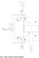
- Figure ( fig 1a ) shows the operating diagram of the piston pump air motor of which a sectional view is shown in figure (1b ) with all its component systems in the position of filling the upper piston chamber (4a) and emptying the lower piston chamber (4b).
- the main air distribution valve (2) When the main air distribution valve (2) is in the downward position ( fig 2 ), it sends compressed air to the air inlet of the upper quick exhaust valve (5a) and communicates the air inlet of the lower quick exhaust valve (5b) to the atmosphere.
- the dynamic air pressure is responsible for positioning the moving part of the upper quick exhaust valve (5a) to allow air to flow into the upper air piston chamber (4a), and for positioning the moving part of the lower quick exhaust valve (5b) to exhaust air from the lower air piston chamber (4b) to the atmosphere via the silencer (6), preventing the exhaust air from returning to the main distributor valve (2) and protecting it against temperature drops and freezing. Since the upper air piston chamber (4a) is supplied with compressed air and the lower air piston chamber (4b) is connected to the atmosphere, the air piston chamber (7) moves downwards.
- the main air distributor valve (2) When the main air distributor valve (2) is in the upward position ( fig 3 ), it sends compressed air to the air inlet of the lower quick exhaust valve (5b) and communicates the air inlet of the upper quick exhaust valve (5a) to the atmosphere.
- the dynamic air pressure is responsible for positioning the moving part of the lower quick exhaust valve (5b) to pass air into the lower air piston chamber (4b), and for positioning the moving part of the upper quick exhaust valve (5a) to exhaust air from the upper air piston chamber (4a) to the atmosphere via the silencer (6), preventing the exhaust air from returning to the main distributor valve (2) and protecting it against temperature drops and freezing. Since the lower air piston chamber (4b) is supplied with compressed air and the upper air piston chamber (4a) is connected to the atmosphere, the air piston moves upwards.
- the limit switch sensors (3a and 3b) can be of any type to actuate the main distributor valve (2) and can have sensing technology of any type such as pneumatic, electrical or mechanical. These sensors may be independent elements attached to the motor from the outside or they may form a constructive part of the motor itself.
- Figure ( fig 4b ) shows a sectional view of a quick exhaust valve with a slide mechanism, the housing of which is part of one of the piston pump parts.
- the quick exhaust slide valve (5a, 5b) has two operating positions which alternate with each change of position of the main air distributor valve (2).
- the air evacuation position occurs when there is no compressed air at the compressed air inlet port (7), because the main distributor valve (2) is in the position that communicates the port (7) of the quick exhaust valve in question with the atmosphere.
- the air piston chamber (4a or 4b) to which the quick exhaust slide valve (5a or 5b) is connected has compressed air which must be exhausted to the atmosphere.
- the compressed air enters the quick exhaust valve with slide mechanism through the air motor port (9), and the dynamic air pressure pushes the moving part (10) to close the compressed air inlet port (7).
- the moving part (10) is placed in this position, the air outlet port to the atmosphere (8) remains open, so that the compressed air in the piston chamber (4a or 4b) is exhausted to the atmosphere.
- the other operating position of the quick exhaust slide valve (5a, 5b), in which the air inlet is represented in the figure ( fig 6 ), is when compressed air is present at the compressed air inlet port (7), because the main distributor valve (2) has been positioned to communicate air pressure to this quick exhaust valve with slide mechanism (5a or 5b).
- the compressed air in the air inlet port (7) pushes the moving part (10) and the dynamic pressure of the air causes the moving part (10) to position itself and maintain the position shown in the image ( fig 6 ) and the flexible element of the moving part to deform elastically, allowing the air to pass through.
- the compressed air flows to the air motor through the motor port (9), while simultaneously the moving part (10) closes the air outlet port to the atmosphere (8).
- the passage from one position to another of the moving part (10) is always a guided linear movement, as part of the moving part (10) remains inside the stationary part (11), in the form of a prismatic or sliding system, with reduced play between the two parts to ensure the guiding effect. This avoids misalignment of the moving part (10) that may cause malfunction due to poor sealing or deterioration of the seal (10).
Landscapes
- Engineering & Computer Science (AREA)
- Mechanical Engineering (AREA)
- General Engineering & Computer Science (AREA)
- Compressors, Vaccum Pumps And Other Relevant Systems (AREA)
- Reciprocating Pumps (AREA)
- Check Valves (AREA)
Abstract
Description
- The present invention relates to a piston pump with quick exhaust slide valves, which allows the air coming from the air piston chambers to be evacuated directly from each chamber to the atmosphere, without needing to travel the return path to the above-mentioned main distributor valve to exit to the atmosphere, preventing the build-up of ice in the main pneumatic distributor control valve, which is used in pneumatically actuated reciprocating piston pumps. The use of quick exhaust valves improves the performance of the pump by reducing the resistance to air flow (or pressure drop) through the internal ducts of the engine, since a large part of this flow is avoided by directly evacuating the piston chambers to the atmosphere, thus reducing the consumption of compressed air.
- The main application of this invention is in the industry sector of pneumatically actuated pumps for the supply of fluids under pressure, such as hydrocarbons, chlorinated hydrocarbons, acids, bases, oils, greases, paints, varnishes, sealants, silicones, adhesives and other chemical products used in industrial processes.
- The invention of the quick exhaust slide valve can be applied to any compressed air system in pneumatic actuators of all types, piston and diaphragm pumps, motors and pneumatic circuits as they can be incorporated into such systems to gain performance, prevent freezing or reduce dimensions.
- Most of the pneumatically actuated piston pumps for transferring fluids under pressure on the market have mechanisms that do not guarantee the removal of air from the air piston chambers without causing the main air distribution valve to freeze under certain operating conditions, such as medium/high pressures, continuous operation and compressed air that has not been adequately dried.
- The sudden expansion of this compressed air causes the temperature inside the motor, and therefore also in the main air distribution valve, to drop below the freezing temperature of the moisture that may be present in the compressed air, producing ice which, in continuous operation, can block the air passages and stop or stall the piston pump of the pneumatic pump. Some models on the market have a mechanism whereby the temperature at the outlet does not fall below freezing temperature. This is achieved by the controlled leakage of compressed air, with a higher temperature than air at atmospheric pressure, from the inlet to the outlet of the main air distribution valve. This method causes excessive air consumption and, under certain circumstances of continuous operation at high pressures, the energy provided is not sufficient and the main air distribution valve also freezes. This party is unaware of the existence of a pneumatic fluid transfer piston pump where the air evacuated from the air piston chambers is discharged directly from the air piston chambers into the environment by means of a quick exhaust valve, which prevents the air from flowing back into the main air distribution valve and causing it to freeze and consequently slow down or even stall and stall the pump.
- The quick exhaust slide valves proposed in the present invention are new and solve and improve two problems of the existing quick exhaust valves. Firstly, they eliminate the possibility of misalignment of its mobile element, thanks to a slide-type design that ensures the guidance of said mobile element, and secondly, they allow the compressed air passage cross section to be increased, reducing the pressure loss and improving the performance of the valve compared to the designs of the same-sized valves existing at present.
- There are no known quick exhaust valves in the current configuration applied to pneumatic piston pumps.
- The air motor that drives the piston pump has a power piston that separates the two air chambers that make up the pump and moves alternately from one chamber to the other, causing the pump to move. The air motor also has a compressed air inlet to a main air distribution valve, which feeds compressed air alternately into the air piston chambers to cause their reciprocating motion aided by the actuation of the end-of-stroke sensors. The quick exhaust valves are located in the communication ports with the two air piston chambers and are intended to evacuate the compressed air from the piston pump piston chambers without passing through the main compressed air distribution valve of the motor.
- Two quick exhaust valves are required for each pneumatically driven piston pump: -one evacuates the air from the upper air piston chamber and the other evacuates the air from the lower air piston chamber. In this way, both chambers have their own valve for evacuating air directly to the outside, preventing the air to be evacuated from having to pass through the main air distribution valve and preventing the sudden expansion of the compressed air from causing the generation of ice in the main distribution valve that could prevent its normal operation and draught, and also reducing the pressure loss from the extraction of compressed air from the motor to the atmosphere. The quick exhaust valves with slide system have a movable element which has a dual function: firstly, when in the air inlet position, it allows air to enter the corresponding air piston chamber; secondly, when in the air exhaust position, it allows air from the air piston chamber to escape directly into the atmosphere via the pump's silencing system and in turn prevents the air from having to return to the main distributor valve before it is released into the environment.
- The invention consists of a piston pump and two quick exhaust valves with slide mechanism, each consisting of:
- a moving part. Such a moving part may consist of a single piece of elastomeric material or an assembly consisting of a rigid structure and two elastomeric sealing elements assembled to it. This moving part alternates between two positions depending on whether compressed air is entering or leaving the air piston chamber, closing the corresponding air port (either the one communicating with the main distributor valve or the one communicating to the atmosphere) and leaving the other one open, alternately.
- a stationary sleeve. The sleeve consists of a rigid part that houses and guides the moving part and provides a sealing layer at the air passage port to the atmosphere.
- a housing containing the moving part and the stationary cylinder sleeve, which in the case of piston air motors may be part of the construction parts of such a motor that benefit from the smaller size required to achieve the same performance as traditional exhaust valves, allowing the motor construction parts to be smaller, or of the same size, but with superior pneumatic performance....";".
- Compared to existing quick exhaust valves, this invention improves on existing quick exhaust valves by removing obstacles in the air passage from the main air distribution valve to the air piston chamber. This is achieved with a moving part of greater length than usual, allowing it to seal against a surface outside the geometric space between the air piston chamber port and the main distributor valve port. Moreover, since the sleeve and the moving part are prismatic in shape, the moving part is always guided by the sleeve, thus avoiding any possibility of misalignment that could lead to irregular operation or even failure, which can occur with existing valves.
- This piston pump with quick exhaust valve has one of its applications in pneumatically driven reciprocating piston pumps for fluid transfer. The piston pump with quick exhaust valve allows the air stored in the air piston chambers of the piston pump's air motor to be exhausted directly into the environment without passing through the internal ducts of the motor or the main air distribution valve, and without causing it to freeze. This prevents the creation of ice in the motor's air ducts and in its main distributor valve, which can cause the piston pump to stop and stall. On the other hand, this arrangement of the quick exhaust valves minimises pressure losses in the motor's operating air circuit, increasing its efficiency and reducing compressed air consumption.
- The piston pump (
fig. 1a ) consists of: - .- a compressed air inlet connection (1),
- .- a main air distributor valve (2),
- .- two piston limit switch sensors (3a and 3b),
- .- air piston chambers (4a and 4b),
- .- quick exhaust slide valves (5a and 5b),
- .- pneumatic piston pump silencing system (6),
- .- air chamber piston (7)
- Quick exhaust valves with slide mechanism (
fig. 4a ) are composed of: - .- compressed air inlet port (7),
- .- air outlet port to the atmosphere (8),
- .- air motor port (9),
- - moving part of quick exhaust slide valve (10),
- .- stationary part of quick exhaust slide valve (11),
- .- quick exhaust slide valve body/housing (12),
-
-
Fig. 1a shows a pneumatic diagram of the pneumatically driven piston pump with quick exhaust valves and slide mechanism. -
Fig. 1b shows a longitudinal section of the piston pump of a pneumatically driven piston pump with quick exhaust valves and slide mechanism. -
Fig. 2 shows a pneumatic diagram of the pneumatically driven piston pump with quick exhaust valves and slide mechanism, operating in a downward direction. -
Fig. 2 shows a pneumatic diagram of the pneumatically driven piston pump with quick exhaust valves and slide mechanism, operating in an upward direction. -
Fig. 4a shows a diagram of the quick exhaust valve with its air inlet port, air outlet port, motor port, moving part, stationary part and housing. -
Fig. 4b shows a longitudinal section of the quick exhaust valve with its air inlet port, air outlet port, motor port, moving part, stationary part and housing. -
Fig. 5 shows a diagram of the quick exhaust slide valve in the air release position. -
Fig. 6 shows a diagram of the quick exhaust slide valve in the air inlet position. - Figure (
fig 1a ) shows the operating diagram of the piston pump air motor of which a sectional view is shown infigure (1b ) with all its component systems in the position of filling the upper piston chamber (4a) and emptying the lower piston chamber (4b). - When the main air distribution valve (2) is in the downward position (
fig 2 ), it sends compressed air to the air inlet of the upper quick exhaust valve (5a) and communicates the air inlet of the lower quick exhaust valve (5b) to the atmosphere. The dynamic air pressure is responsible for positioning the moving part of the upper quick exhaust valve (5a) to allow air to flow into the upper air piston chamber (4a), and for positioning the moving part of the lower quick exhaust valve (5b) to exhaust air from the lower air piston chamber (4b) to the atmosphere via the silencer (6), preventing the exhaust air from returning to the main distributor valve (2) and protecting it against temperature drops and freezing. Since the upper air piston chamber (4a) is supplied with compressed air and the lower air piston chamber (4b) is connected to the atmosphere, the air piston chamber (7) moves downwards. - When the air chamber piston (7) reaches its downward stroke end, the lower stroke end sensor (3b) is actuated by the air piston (7), causing the main distributor valve (2) to switch to its upward position as shown in the figure (
fig 3 ). - When the main air distributor valve (2) is in the upward position (
fig 3 ), it sends compressed air to the air inlet of the lower quick exhaust valve (5b) and communicates the air inlet of the upper quick exhaust valve (5a) to the atmosphere. The dynamic air pressure is responsible for positioning the moving part of the lower quick exhaust valve (5b) to pass air into the lower air piston chamber (4b), and for positioning the moving part of the upper quick exhaust valve (5a) to exhaust air from the upper air piston chamber (4a) to the atmosphere via the silencer (6), preventing the exhaust air from returning to the main distributor valve (2) and protecting it against temperature drops and freezing. Since the lower air piston chamber (4b) is supplied with compressed air and the upper air piston chamber (4a) is connected to the atmosphere, the air piston moves upwards. - The limit switch sensors (3a and 3b) can be of any type to actuate the main distributor valve (2) and can have sensing technology of any type such as pneumatic, electrical or mechanical. These sensors may be independent elements attached to the motor from the outside or they may form a constructive part of the motor itself.
- Figure (
fig 4b ) shows a sectional view of a quick exhaust valve with a slide mechanism, the housing of which is part of one of the piston pump parts. - The quick exhaust slide valve (5a, 5b) has two operating positions which alternate with each change of position of the main air distributor valve (2).
- One of these two positions, the air evacuation position (
fig 5 ), occurs when there is no compressed air at the compressed air inlet port (7), because the main distributor valve (2) is in the position that communicates the port (7) of the quick exhaust valve in question with the atmosphere. In this position, the air piston chamber (4a or 4b) to which the quick exhaust slide valve (5a or 5b) is connected has compressed air which must be exhausted to the atmosphere. The compressed air enters the quick exhaust valve with slide mechanism through the air motor port (9), and the dynamic air pressure pushes the moving part (10) to close the compressed air inlet port (7). When the moving part (10) is placed in this position, the air outlet port to the atmosphere (8) remains open, so that the compressed air in the piston chamber (4a or 4b) is exhausted to the atmosphere. - The other operating position of the quick exhaust slide valve (5a, 5b), in which the air inlet is represented in the figure (
fig 6 ), is when compressed air is present at the compressed air inlet port (7), because the main distributor valve (2) has been positioned to communicate air pressure to this quick exhaust valve with slide mechanism (5a or 5b). - In this position, the compressed air in the air inlet port (7) pushes the moving part (10) and the dynamic pressure of the air causes the moving part (10) to position itself and maintain the position shown in the image (
fig 6 ) and the flexible element of the moving part to deform elastically, allowing the air to pass through. In this way, the compressed air flows to the air motor through the motor port (9), while simultaneously the moving part (10) closes the air outlet port to the atmosphere (8). - The passage from one position to another of the moving part (10) is always a guided linear movement, as part of the moving part (10) remains inside the stationary part (11), in the form of a prismatic or sliding system, with reduced play between the two parts to ensure the guiding effect. This avoids misalignment of the moving part
(10) that may cause malfunction due to poor sealing or deterioration of the seal (10).
Claims (9)
- Piston pump with quick exhaust slide valves characterised by a single piston in the air chamber with reciprocating motion separating the piston chambers and two quick exhaust valves, one for each air piston chamber, which prevent, by means of their sliding mechanism, the evacuation of the air from the air piston chambers through the main air distribution valve, preventing it from freezing and allowing it to be discharged directly into the environment, thus avoiding its freezing. The air is then discharged directly into the environment through the main exhaust system of the piston pump which consists of:• at least one compressed air inlet connection (1),• at least one main air distribution valve (2),• at least two piston limit switch sensors (3a and 3b),• air piston chambers (4a and 4b),• at least two quick exhaust slide valves (5a and 5b),• at least one pneumatic piston pump silencing system (6),• air chamber piston (7),Quick exhaust slide valves have a guided slide or moving part which allows air to enter the air piston chamber on the one hand, and on the other hand, when the stroke is reversed, to be exhausted directly from the air piston chamber into the environment via the main exhaust system of the pump.The quick exhaust valves consist of a prismatic slide system with a moving part, a stationary sleeve and housing, so that the moving part has a linear travel guided by the stationary part. The valve has 3 ports, one of which is always open, and the other two are closed by the moving part, one in each operating position of the moving part. The moving part is displaced by the dynamic pressure of the compressed air, depending on whether it arrives at one port or the other and consists of:• compressed air inlet port (7),• air outlet port to the atmosphere (8),• air motor port (9)• moving part of quick exhaust slide valve (10),• stationary part of quick exhaust slide valve (11),• quick exhaust slide valve body/housing (12),
- Piston pump with quick exhaust sliding valves according to the first claim, characterised in that the quick exhaust valves are independent accessories externally coupled to the piston pump, and these accessories can be used in any pneumatic system as independent quick exhaust valves.
- Piston pump with quick exhaust slide valves according to the first claim, characterised in that the quick exhaust mechanism can be electronically operated.
- Piston pump with quick exhaust slide valves according to the first claim, characterised in that the moving part of the valves has a part of flexible and elastic material which deforms elastically when it receives air under pressure from its convex side, contracting and allowing the passage of pressurised air and, when it receives the pressurised air from its concave side, it elastically deforms and expands to fill the entire cylindrical cross-section of the housing. The elastic part of the housing (casing) exerts the necessary thrust force to move the moving part until it butts against the housing (casing), sealing the air inlet port of the valve.
- Piston pump with quick exhaust sliding valves according to the previous claim, characterised in that the mobile element has a part of flexible and elastic material located in the area that contacts the stationary element in one of the operating positions, sealing the air outlet port of the valve.
- Piston pump with quick exhaust slide valves according to the two previous claims, characterised in that the moving part has the two flexible parts indicated above assembled by means of fittings or bolted to a structure of rigid material, whether metallic or plastic.
- Piston pump with quick exhaust slide valves according to claims 2, 4, 5 and 6, characterised in that the moving part is entirely made of a single piece of flexible and elastic material.
- Piston pump with quick exhaust slide valves according to the first claim, characterised in that the valves themselves are integrated in the pneumatic actuator on which they are to operate. Thus, the quick exhaust valve housing is not a separate part, but is part of one of the parts of the actuator in question, which has housings into which the moving and stationary parts of the quick exhaust valves are inserted.
- Piston pump with quick exhaust slide valves according to the first claim, characterised in that the design of the valves prevents the possibility of misalignment of its mobile element, ensuring the guidance of said moving part, which makes it possible to lengthen its travel to increase the section of the compressed air passage, reducing load loss and improving the performance of the valve with respect to currently existing designs of the same size, which must have a short travel so that the moving part, without guidance, does not become misaligned and cause leaks and/or malfunctioning.
Applications Claiming Priority (2)
| Application Number | Priority Date | Filing Date | Title |
|---|---|---|---|
| ES202330247A ES2984137B2 (en) | 2023-03-24 | 2023-03-24 | PISTON PUMP WITH QUICK EXHAUST SLIDING VALVES |
| PCT/IB2024/052636 WO2024201212A1 (en) | 2023-03-24 | 2024-03-19 | Piston pump with quick exhaust slide valves |
Publications (2)
| Publication Number | Publication Date |
|---|---|
| EP4549699A1 true EP4549699A1 (en) | 2025-05-07 |
| EP4549699A4 EP4549699A4 (en) | 2026-04-22 |
Family
ID=92903822
Family Applications (1)
| Application Number | Title | Priority Date | Filing Date |
|---|---|---|---|
| EP24778378.0A Pending EP4549699A4 (en) | 2023-03-24 | 2024-03-19 | Piston pump with quick-release slide valves |
Country Status (9)
| Country | Link |
|---|---|
| US (1) | US20260092600A1 (en) |
| EP (1) | EP4549699A4 (en) |
| JP (1) | JP2026508714A (en) |
| KR (1) | KR20250166839A (en) |
| CN (1) | CN119790216A (en) |
| AU (1) | AU2024246451A1 (en) |
| CA (1) | CA3263474A1 (en) |
| ES (1) | ES2984137B2 (en) |
| WO (1) | WO2024201212A1 (en) |
Family Cites Families (9)
| Publication number | Priority date | Publication date | Assignee | Title |
|---|---|---|---|---|
| GB412960A (en) * | 1933-01-02 | 1934-07-02 | Dewandre Co Ltd C | Improvements in or relating to fluid-pressure relays for controlling the transmission gear of marine engines |
| US2772813A (en) * | 1952-11-07 | 1956-12-04 | L Heureux Phillaus | Grease can receiving grease ejector |
| FR76804E (en) * | 1959-07-11 | 1961-12-08 | High pressure liquid injector | |
| US4189983A (en) * | 1977-01-04 | 1980-02-26 | Zahnradfabrik Friedrichshafen Ag | Servomotor pressure control responsive to piston travel |
| DE2823667C2 (en) * | 1978-05-31 | 1985-11-28 | Erich 7990 Friedrichshafen Roser | Air motor |
| JP3240001B2 (en) * | 1990-11-30 | 2001-12-17 | エスエムシー株式会社 | Pneumatic or vacuum pressure hand tools |
| JPH05209601A (en) * | 1992-01-31 | 1993-08-20 | Canon Inc | Cylinder device and control thereof |
| US5616005A (en) * | 1994-11-08 | 1997-04-01 | Regents Of The University Of California | Fluid driven recipricating apparatus |
| NO311452B1 (en) * | 2000-02-14 | 2001-11-26 | Schmidt & Co Gmbh Kranz | Pneumatically operated hydraulic pump |
-
2023
- 2023-03-24 ES ES202330247A patent/ES2984137B2/en active Active
-
2024
- 2024-03-19 WO PCT/IB2024/052636 patent/WO2024201212A1/en not_active Ceased
- 2024-03-19 CN CN202480003987.4A patent/CN119790216A/en active Pending
- 2024-03-19 CA CA3263474A patent/CA3263474A1/en active Pending
- 2024-03-19 US US19/111,110 patent/US20260092600A1/en active Pending
- 2024-03-19 EP EP24778378.0A patent/EP4549699A4/en active Pending
- 2024-03-19 JP JP2025511602A patent/JP2026508714A/en active Pending
- 2024-03-19 AU AU2024246451A patent/AU2024246451A1/en active Pending
- 2024-03-19 KR KR1020257008632A patent/KR20250166839A/en active Pending
Also Published As
| Publication number | Publication date |
|---|---|
| AU2024246451A1 (en) | 2025-01-30 |
| ES2984137B2 (en) | 2025-09-23 |
| ES2984137A1 (en) | 2024-10-28 |
| CN119790216A (en) | 2025-04-08 |
| CA3263474A1 (en) | 2025-06-06 |
| KR20250166839A (en) | 2025-11-28 |
| EP4549699A4 (en) | 2026-04-22 |
| JP2026508714A (en) | 2026-03-12 |
| WO2024201212A1 (en) | 2024-10-03 |
| US20260092600A1 (en) | 2026-04-02 |
Similar Documents
| Publication | Publication Date | Title |
|---|---|---|
| KR100298229B1 (en) | Double diaphragm pump having two-stage air valve actuator | |
| JP4547451B2 (en) | Bellows pump and operation method of bellows pump | |
| US6589027B2 (en) | Double acting reciprocating motor with uni-directional fluid flow | |
| EP0708244B1 (en) | Double diaphragm pump | |
| EP2519752B1 (en) | Apparatus to increase a force of an actuator having an override apparatus | |
| US6722256B2 (en) | Reduced icing valves and gas-driven motor and diaphragm pump incorporating same | |
| US12129843B2 (en) | Breather valve | |
| CN110159603B (en) | Method and device for venting the suction side of a synthetically commutated hydraulic pump | |
| US20260092600A1 (en) | Piston pump with quick exhaust slide valves | |
| KR101830165B1 (en) | Actuator for valve | |
| TWI432647B (en) | Reciprocating piston pump with air valve, detent and poppets | |
| CN221033412U (en) | Anti-jamming self-reciprocating pneumatic motor with operation monitoring function | |
| CN113464408B (en) | Bellows pump case and adopt its bellows pump | |
| KR100936143B1 (en) | Hydraulic pump with air compression | |
| JP2001050406A (en) | Multi-way valve | |
| CN111577566B (en) | Pneumatic oil pressure pumping and piston reversing method | |
| CN211737632U (en) | Automatic reciprocating cylinder who switches | |
| KR100486847B1 (en) | Pressure Intensifying Cylinder | |
| KR101047656B1 (en) | Synchronous Actuator Structure of Wet Double Clutch Transmission | |
| CN221973961U (en) | Automatic reversing cylinder | |
| JPS6046281B2 (en) | Automatic reciprocating motion control device for fluid pressure cylinders | |
| CN110725826A (en) | Reciprocating piston motor, motor-pump assembly and method of driving a pump | |
| CN101349272A (en) | discharge valve | |
| CN121952921A (en) | Miniature bidirectional reciprocating supercharger | |
| KR200269267Y1 (en) | A control valve for air cylinder |
Legal Events
| Date | Code | Title | Description |
|---|---|---|---|
| STAA | Information on the status of an ep patent application or granted ep patent |
Free format text: STATUS: THE INTERNATIONAL PUBLICATION HAS BEEN MADE |
|
| PUAI | Public reference made under article 153(3) epc to a published international application that has entered the european phase |
Free format text: ORIGINAL CODE: 0009012 |
|
| STAA | Information on the status of an ep patent application or granted ep patent |
Free format text: STATUS: REQUEST FOR EXAMINATION WAS MADE |
|
| 17P | Request for examination filed |
Effective date: 20250130 |
|
| AK | Designated contracting states |
Kind code of ref document: A1 Designated state(s): AL AT BE BG CH CY CZ DE DK EE ES FI FR GB GR HR HU IE IS IT LI LT LU LV MC ME MK MT NL NO PL PT RO RS SE SI SK SM TR |
|
| A4 | Supplementary search report drawn up and despatched |
Effective date: 20260325 |
|
| RIC1 | Information provided on ipc code assigned before grant |
Ipc: F01B 3/00 20060101AFI20260319BHEP Ipc: F04B 5/02 20060101ALI20260319BHEP Ipc: F04B 9/125 20060101ALI20260319BHEP Ipc: F04B 39/08 20060101ALI20260319BHEP Ipc: F04B 39/10 20060101ALI20260319BHEP |