EP4549652A1 - Balise protection - Google Patents
Balise protection Download PDFInfo
- Publication number
- EP4549652A1 EP4549652A1 EP24020123.6A EP24020123A EP4549652A1 EP 4549652 A1 EP4549652 A1 EP 4549652A1 EP 24020123 A EP24020123 A EP 24020123A EP 4549652 A1 EP4549652 A1 EP 4549652A1
- Authority
- EP
- European Patent Office
- Prior art keywords
- balise
- protection
- covering
- channel
- railway
- Prior art date
- Legal status (The legal status is an assumption and is not a legal conclusion. Google has not performed a legal analysis and makes no representation as to the accuracy of the status listed.)
- Pending
Links
Images

Classifications
-
- E—FIXED CONSTRUCTIONS
- E01—CONSTRUCTION OF ROADS, RAILWAYS, OR BRIDGES
- E01B—PERMANENT WAY; PERMANENT-WAY TOOLS; MACHINES FOR MAKING RAILWAYS OF ALL KINDS
- E01B26/00—Tracks or track components not covered by any one of the preceding groups
-
- B—PERFORMING OPERATIONS; TRANSPORTING
- B61—RAILWAYS
- B61L—GUIDING RAILWAY TRAFFIC; ENSURING THE SAFETY OF RAILWAY TRAFFIC
- B61L3/00—Devices along the route for controlling devices on the vehicle or train, e.g. to release brake or to operate a warning signal
- B61L3/02—Devices along the route for controlling devices on the vehicle or train, e.g. to release brake or to operate a warning signal at selected places along the route, e.g. intermittent control simultaneous mechanical and electrical control
- B61L3/08—Devices along the route for controlling devices on the vehicle or train, e.g. to release brake or to operate a warning signal at selected places along the route, e.g. intermittent control simultaneous mechanical and electrical control controlling electrically
- B61L3/12—Devices along the route for controlling devices on the vehicle or train, e.g. to release brake or to operate a warning signal at selected places along the route, e.g. intermittent control simultaneous mechanical and electrical control controlling electrically using magnetic or electrostatic induction; using radio waves
- B61L3/121—Devices along the route for controlling devices on the vehicle or train, e.g. to release brake or to operate a warning signal at selected places along the route, e.g. intermittent control simultaneous mechanical and electrical control controlling electrically using magnetic or electrostatic induction; using radio waves using magnetic induction
-
- B—PERFORMING OPERATIONS; TRANSPORTING
- B61—RAILWAYS
- B61L—GUIDING RAILWAY TRAFFIC; ENSURING THE SAFETY OF RAILWAY TRAFFIC
- B61L27/00—Central railway traffic control systems; Trackside control; Communication systems specially adapted therefor
- B61L27/20—Trackside control of safe travel of vehicle or train, e.g. braking curve calculation
- B61L2027/202—Trackside control of safe travel of vehicle or train, e.g. braking curve calculation using European Train Control System [ETCS]
-
- B—PERFORMING OPERATIONS; TRANSPORTING
- B61—RAILWAYS
- B61L—GUIDING RAILWAY TRAFFIC; ENSURING THE SAFETY OF RAILWAY TRAFFIC
- B61L3/00—Devices along the route for controlling devices on the vehicle or train, e.g. to release brake or to operate a warning signal
- B61L3/02—Devices along the route for controlling devices on the vehicle or train, e.g. to release brake or to operate a warning signal at selected places along the route, e.g. intermittent control simultaneous mechanical and electrical control
- B61L3/08—Devices along the route for controlling devices on the vehicle or train, e.g. to release brake or to operate a warning signal at selected places along the route, e.g. intermittent control simultaneous mechanical and electrical control controlling electrically
- B61L3/12—Devices along the route for controlling devices on the vehicle or train, e.g. to release brake or to operate a warning signal at selected places along the route, e.g. intermittent control simultaneous mechanical and electrical control controlling electrically using magnetic or electrostatic induction; using radio waves
- B61L3/125—Devices along the route for controlling devices on the vehicle or train, e.g. to release brake or to operate a warning signal at selected places along the route, e.g. intermittent control simultaneous mechanical and electrical control controlling electrically using magnetic or electrostatic induction; using radio waves using short-range radio transmission
-
- B—PERFORMING OPERATIONS; TRANSPORTING
- B61—RAILWAYS
- B61L—GUIDING RAILWAY TRAFFIC; ENSURING THE SAFETY OF RAILWAY TRAFFIC
- B61L3/00—Devices along the route for controlling devices on the vehicle or train, e.g. to release brake or to operate a warning signal
- B61L3/02—Devices along the route for controlling devices on the vehicle or train, e.g. to release brake or to operate a warning signal at selected places along the route, e.g. intermittent control simultaneous mechanical and electrical control
- B61L3/08—Devices along the route for controlling devices on the vehicle or train, e.g. to release brake or to operate a warning signal at selected places along the route, e.g. intermittent control simultaneous mechanical and electrical control controlling electrically
- B61L3/12—Devices along the route for controlling devices on the vehicle or train, e.g. to release brake or to operate a warning signal at selected places along the route, e.g. intermittent control simultaneous mechanical and electrical control controlling electrically using magnetic or electrostatic induction; using radio waves
- B61L3/126—Constructional details
Definitions
- the invention relates to balise protection, specifically to balise protection for communication with a railway vehicle mounted in the space between the rails of a railway track.
- the ETCS railway system uses a balise designated as an ETCS Eurobalise as one of the basic means of transferring information from the trackside equipment to the rolling stock.
- This balise is located between the rails. Between the rails, however, the balise is exposed to an increased risk of mechanical damage or destruction by hanging objects and falling ice from rail vehicles, flying gravel thrown by rail vehicles, etc. This can lead to damage to the balise and thereby to a reduction of the availability of information transmitted from individual balises to the rail vehicle, due to their malfunctions. Subsequently, this can also cause a possible reduction in the operability of the entire ETCS system. Additionally, replacing destroyed balises is quite expensive.
- balises are not sufficiently protected and therefore a considerable number of them are damaged and eventually destroyed.
- the goal of the invention is to design a balise protection that will adequately protect the balise itself, while the protection itself will be highly resistant to damage, both in the above-mentioned ways from passing rail vehicles and also by other environmental influences, while at the same time it will be simple to manufacture and therefore inexpensive.
- a balise in particular the protection of a balise for communication with a railway vehicle fixed in the space between the rails of a railway track, according to the invention, characterised by that it contains at least one upwardly rising upwardly curved covering part arranged in the direction of travel of the rolling stock, with the upwardly curved covering part being connected to a covering channel in which the balise is arranged.
- the advantage is that the overall construction and especially the shape of the covering part ensure increased resistance both against damage to the protection itself and, above all, safely protect the balise covered in the covering channel.
- Another advantage is that if a moving object collides at speed with the balise protection, thanks to the shape of the covering part, the moving object will bounce off and fly aside at a safe distance from the balise when it hits the covering part.
- the covering channel connects to the covering part at its highest point, and this highest point is placed higher than the top surface of the balise. This ensures perfect overlapping of the channel with the balise.
- At least one covering part and the covering channel form a single unit. This ensures sufficient resistance in the event of an impact.
- the balise protection contains two covering parts arranged in the direction of movement of the railway vehicle, with the covering parts being connected to the covering channel.
- the advantage is that the balise is thus protected against the movement of dangerous objects when the railway vehicle moves in any direction.
- balise is attached to the bottom of the covering channel. This ensures that the balise is set in a safe place.
- balise is simultaneously attached to the bottom of the covering channel and to the surface of the railway track. This ensures a stable position of the entire balise protection with the balise.
- the surface of the railway track for attaching the balise with protection is, to advantage, the track superstructure.
- a cross bar is arranged between the balise and the bottom of the covering channel, which is further arranged below the rails.
- the cross bar can be attached under the rails, or it can be fixed under the bolts attaching the rails to the sleeper.
- the balise protection is pressed by the cross bar against the track superstructure, whereby the balise protection is firmly set in the designated place.
- the surface of the railway track for attaching the balise with protection is a railway sleeper.
- at least one spacer plate is arranged between the balise and the railway sleeper.
- at least one spacer pad is arranged between the balise and the bottom of the covering channel. The balise protection is again firmly set in the designated place.
- balise is attached to the bottom of the covering channel and to the surface of the railway track by at least one connecting means.
- the covering part is made as flexible, and in the most advantageous variant the covering part is made of a layered composite material. This increases impact resistance and at the same time, when struck by a flying object, it deflects the object to a safe height to fly over the balise without damaging it.
- the main advantage of the balise protection according to the invention is that it provides safe protection of balises against a direct hit or hooking by loose objects hanging from passing rail vehicles, such as a loose air hose, a loose coupling, etc.
- the balise protection will safely absorb such a blow from a free-hanging object and thanks to the curved surface of the covering part, the object slides beyond the protection of the balise or bounces off it.
- the shaped design also enables easy and quick mounting on balise fastening systems.
- the shape of the balise protection design is also sufficiently flexible and strong, with this being verified by testing that it resists the impact of objects hanging freely or falling from the railway vehicles very well, even at high speeds of these vehicles, with the tests being carried out at a speed of 160 km/h.
- Another advantage is that the balise protection is very easy to install, reducing the installation time at the rail tracks. This is very advantageous because the installation is cheaper and, above all, safer due to the reduction of the time spent by workers at the rail tracks.
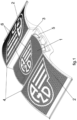
- fig. 1 shows a three-dimensional view of the assembled balise protection in the design for attaching to a railway sleeper
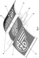
- fig. 2 shows an exploded three-dimensional view of the balise protection in the design for attaching to a railway sleeper
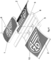
- fig. 3 shows a three-dimensional view of the assembled balise protection in the design for attachment between rails
- fig. 4 shows an exploded three-dimensional view of the balise protection in the design for attachment between rails.
- a protection of a balise 1 for communication with a rail vehicle ( fig.1 , fig.2 ), which is arranged in the not-illustrated space between the rails of the railway track, containing two upwardly rising upwardly curved covering parts 2 arranged in the direction of travel of the rail vehicle.
- a rail vehicle fig.1 , fig.2
- the protection of the balise 1 for one-way operation may contain only one covering part 2 .
- the covering parts 2 are designed as being flexible.
- the covering parts 2 and the covering channel 3 form one indivisible unit, while being made of a layered composite material, which is fibreglass composite.
- the balise 1 is simultaneously attached by two connecting means 6 , which are mounting bolts, through the holes 10 in the bottom 5 of the covering channel 3 , to the surface of the railway track, which is a railway sleeper.
- balise 1 and the bottom 5 of the covering channel 3 Arranged between the balise 1 and the bottom 5 of the covering channel 3 , are two spacer pads 7 .
- a spacer plate 9 Arranged between the balise 1 and the railway sleeper is a spacer plate 9 .
- the protection of the balise 1 for communication with a rail vehicle ( fig.3 , fig.4 ), which is arranged in the not-illustrated space between the rails of the railway track, contains two upwardly rising, upwardly curved covering parts 2 arranged in the direction of travel of the rail vehicle.
- the covering channel 3 To the upwardly curved covering part 2 at its highest place 4 is connected the covering channel 3 , in which the balise 1 is arranged.
- the protection of the balise 1 for one-way operation may contain only one covering part 2 .
- the covering parts 2 are designed as being flexible.
- the covering parts 2 and the covering channel 3 form one indivisible unit, while being made of a layered composite material, which is fibreglass composite.
- the balise 1 is simultaneously attached by two connecting means 6 , which are mounting bolts, to the cross bar 8 , which is further arranged with its not shown ends under the not shown rails.
- These connecting means 6 pass through the holes 10 in the bottom 5 of the covering channel 3 and ensure the protection of the balise 1 against unwanted longitudinal or transverse movement.
- the cross bar 8 presses the protection of the balise 1 against the surface of the railway track, which is the track superstructure.
- the balise protection can be used as protection of a balise for communication with a railway vehicle, especially as balise protection in the ETCS (European Train Control System) system, against direct impact or hooking by loose objects hanging from passing rail vehicles.
- ETCS European Train Control System
Landscapes
- Engineering & Computer Science (AREA)
- Mechanical Engineering (AREA)
- Architecture (AREA)
- Civil Engineering (AREA)
- Structural Engineering (AREA)
- Train Traffic Observation, Control, And Security (AREA)
Abstract
A balise (1) protection, in particular the balise (1) protection for communication with a railway vehicle arranged in the space between the rails of a railway track, which includes at least one upwardly rising upwardly curved covering part (2) arranged in the direction of travel of the railway vehicle, with the upwardly curved covering part (2 ) connected to a covering channel (3), in which the balise (1) is arranged.
Description
- The invention relates to balise protection, specifically to balise protection for communication with a railway vehicle mounted in the space between the rails of a railway track.
- At present, it is known that the ETCS railway system uses a balise designated as an ETCS Eurobalise as one of the basic means of transferring information from the trackside equipment to the rolling stock. This balise is located between the rails. Between the rails, however, the balise is exposed to an increased risk of mechanical damage or destruction by hanging objects and falling ice from rail vehicles, flying gravel thrown by rail vehicles, etc. This can lead to damage to the balise and thereby to a reduction of the availability of information transmitted from individual balises to the rail vehicle, due to their malfunctions. Subsequently, this can also cause a possible reduction in the operability of the entire ETCS system. Additionally, replacing destroyed balises is quite expensive.
- The arrangement of balises in the space between the rails of a railway track, without special protection, is known for example from the patent documents
EP3369861 A1 andKR 101273202 B1 - In view of the above, various types of mechanical protection are added to the balises to protect the balises from mechanical damage. This is often insufficient, because the protections used are easily damaged not only in the above-mentioned ways, but also, for example, by simply stepping on and thereby destroying the protection by a person or animal that happens to be in the area where the balise is placed. This disrupts the function of the balise's protection, and the balise itself is then directly threatened with destruction.
- The main disadvantage of the current state of the art is that the balises are not sufficiently protected and therefore a considerable number of them are damaged and eventually destroyed.
- The goal of the invention is to design a balise protection that will adequately protect the balise itself, while the protection itself will be highly resistant to damage, both in the above-mentioned ways from passing rail vehicles and also by other environmental influences, while at the same time it will be simple to manufacture and therefore inexpensive.
- The mentioned shortcomings are largely eliminated and the objectives of the invention are fulfilled by the protection of a balise, in particular the protection of a balise for communication with a railway vehicle fixed in the space between the rails of a railway track, according to the invention, characterised by that it contains at least one upwardly rising upwardly curved covering part arranged in the direction of travel of the rolling stock, with the upwardly curved covering part being connected to a covering channel in which the balise is arranged. The advantage is that the overall construction and especially the shape of the covering part ensure increased resistance both against damage to the protection itself and, above all, safely protect the balise covered in the covering channel. Another advantage is that if a moving object collides at speed with the balise protection, thanks to the shape of the covering part, the moving object will bounce off and fly aside at a safe distance from the balise when it hits the covering part.
- It is to advantage if the covering channel connects to the covering part at its highest point, and this highest point is placed higher than the top surface of the balise. This ensures perfect overlapping of the channel with the balise.
- It is also to advantage if at least one covering part and the covering channel form a single unit. This ensures sufficient resistance in the event of an impact.
- It is also very advantageous if the balise protection contains two covering parts arranged in the direction of movement of the railway vehicle, with the covering parts being connected to the covering channel. The advantage is that the balise is thus protected against the movement of dangerous objects when the railway vehicle moves in any direction.
- Furthermore, it is to advantage if the balise is attached to the bottom of the covering channel. This ensures that the balise is set in a safe place.
- It is also to advantage when the balise is simultaneously attached to the bottom of the covering channel and to the surface of the railway track. This ensures a stable position of the entire balise protection with the balise.
- According to one variant, the surface of the railway track for attaching the balise with protection is, to advantage, the track superstructure. In this case, it is advantageous if a cross bar is arranged between the balise and the bottom of the covering channel, which is further arranged below the rails. The cross bar can be attached under the rails, or it can be fixed under the bolts attaching the rails to the sleeper. The balise protection is pressed by the cross bar against the track superstructure, whereby the balise protection is firmly set in the designated place.
- According to the second variant, the surface of the railway track for attaching the balise with protection is a railway sleeper. In this case, it is to advantage if at least one spacer plate is arranged between the balise and the railway sleeper. And at the same time, it is to advantage if at least one spacer pad is arranged between the balise and the bottom of the covering channel. The balise protection is again firmly set in the designated place.
- In both variants, it is also to advantage if the balise is attached to the bottom of the covering channel and to the surface of the railway track by at least one connecting means.
- It is very advantageous if the covering part is made as flexible, and in the most advantageous variant the covering part is made of a layered composite material. This increases impact resistance and at the same time, when struck by a flying object, it deflects the object to a safe height to fly over the balise without damaging it.
- The main advantage of the balise protection according to the invention is that it provides safe protection of balises against a direct hit or hooking by loose objects hanging from passing rail vehicles, such as a loose air hose, a loose coupling, etc. The balise protection will safely absorb such a blow from a free-hanging object and thanks to the curved surface of the covering part, the object slides beyond the protection of the balise or bounces off it. The shaped design also enables easy and quick mounting on balise fastening systems. The shape of the balise protection design is also sufficiently flexible and strong, with this being verified by testing that it resists the impact of objects hanging freely or falling from the railway vehicles very well, even at high speeds of these vehicles, with the tests being carried out at a speed of 160 km/h. Another advantage is that the balise protection is very easy to install, reducing the installation time at the rail tracks. This is very advantageous because the installation is cheaper and, above all, safer due to the reduction of the time spent by workers at the rail tracks.
- The invention will be explained in more detail with the help of drawings, in which
fig. 1 shows a three-dimensional view of the assembled balise protection in the design for attaching to a railway sleeper,fig. 2 shows an exploded three-dimensional view of the balise protection in the design for attaching to a railway sleeper,fig. 3 shows a three-dimensional view of the assembled balise protection in the design for attachment between rails, andfig. 4 shows an exploded three-dimensional view of the balise protection in the design for attachment between rails. - A protection of a
balise 1 for communication with a rail vehicle (fig.1 ,fig.2 ), which is arranged in the not-illustrated space between the rails of the railway track, containing two upwardly rising upwardly curved coveringparts 2 arranged in the direction of travel of the rail vehicle. To the upwardly curved coveringpart 2 at itshighest place 4 is connected the coveringchannel 3, in which thebalise 1 is arranged. As a variant, the protection of thebalise 1 for one-way operation may contain only one coveringpart 2. - The covering
parts 2 are designed as being flexible. - The covering
parts 2 and the coveringchannel 3 form one indivisible unit, while being made of a layered composite material, which is fibreglass composite. - The
balise 1 is simultaneously attached by twoconnecting means 6, which are mounting bolts, through theholes 10 in thebottom 5 of the coveringchannel 3, to the surface of the railway track, which is a railway sleeper. - Arranged between the
balise 1 and thebottom 5 of the coveringchannel 3, are twospacer pads 7. - Arranged between the
balise 1 and the railway sleeper is aspacer plate 9. - The protection of the
balise 1 for communication with a rail vehicle (fig.3 ,fig.4 ), which is arranged in the not-illustrated space between the rails of the railway track, contains two upwardly rising, upwardly curved coveringparts 2 arranged in the direction of travel of the rail vehicle. To the upwardly curved coveringpart 2 at itshighest place 4 is connected the coveringchannel 3, in which thebalise 1 is arranged. As a variant, the protection of thebalise 1 for one-way operation may contain only one coveringpart 2. - The covering
parts 2 are designed as being flexible. - The covering
parts 2 and the coveringchannel 3 form one indivisible unit, while being made of a layered composite material, which is fibreglass composite. - The
balise 1 is simultaneously attached by twoconnecting means 6, which are mounting bolts, to thecross bar 8, which is further arranged with its not shown ends under the not shown rails. These connecting means 6 pass through theholes 10 in thebottom 5 of the coveringchannel 3 and ensure the protection of thebalise 1 against unwanted longitudinal or transverse movement. - The
cross bar 8 presses the protection of thebalise 1 against the surface of the railway track, which is the track superstructure. - The balise protection, according to the invention, can be used as protection of a balise for communication with a railway vehicle, especially as balise protection in the ETCS (European Train Control System) system, against direct impact or hooking by loose objects hanging from passing rail vehicles.
-
- 1
- balise
- 2
- covering part
- 3
- covering channel
- 4
- the highest place
- 5
- the bottom of the covering channel
- 6
- connecting means
- 7
- spacer pad
- 8
- cross bar
- 9
- spacer plate
- 10
- holes
Claims (14)
- A balise protection, specifically the balise protection of a balise (1) for communication with a railway vehicle arranged in the space between the rails of a railway track, characterised by that it contains at least one upwardly rising curved covering part (2) arranged in the direction of travel of the railway vehicle, with the upwardly curved covering part (2) being connected to a covering channel (3), in which the balise (1) is arranged.
- The balise protection, according to claim 1, characterised by that the covering channel (3) is connected to the covering part (2) at its highest point (4).
- The balise protection according to either one of claims 1 and 2, characterised by that at least one covering part (2) and the covering channel (3) form a single unit.
- The balise protection, according to any one of claims 1 to 3, characterised by that it contains two covering parts (2) arranged in the direction of movement of the rail vehicle, with the covering parts (2) being connected to the covering channel (3).
- The balise protection according to any one of claims 1 to 4, characterised by that the balise (1) is attached to the bottom (5) of the covering channel (3).
- The balise protection, according to any one of claims 1 to 5, characterised by that the balise (1) is simultaneously attached to the bottom (5) of the covering channel (3) and to the surface of the railway track.
- The balise protection, according to claim 6, characterised by that the surface of the railway track is the track superstructure.
- The balise protection, according to claim 6, characterised by that the surface of the railway track is a railway sleeper.
- The balise protection, according to any one of claims 5 to 8, characterised by that the balise (1) is attached to the bottom (5) of the covering channel (3) and to the surface of the railway track by at least one connecting means (6).
- The balise protection according to any one of claims 5 to 9, characterised by that between the balise (1) and the bottom (5) of the covering channel (3) at least one spacer pad (7) is arranged.
- The balise protection, according to any one of claims 5 to 9, characterised by that between the balise (1) and the bottom (5) of the covering channel (3), a cross bar (8) is arranged which is further arranged under the rail tracks.
- The balise protection according to any one of claims 8 to 10, characterised by that between the balise (1) and the railway sleeper, a spacer plate (9) is arranged.
- The balise protection according to any one of claims 1 to 12, characterised by that the covering part (2) is made to be flexible.
- The balise protection according to any one of claims 1 to 13, characterised by that the covering part (2) is made of a laminated composite material.
Applications Claiming Priority (1)
| Application Number | Priority Date | Filing Date | Title |
|---|---|---|---|
| CZ20234142 | 2023-10-31 |
Publications (1)
| Publication Number | Publication Date |
|---|---|
| EP4549652A1 true EP4549652A1 (en) | 2025-05-07 |
Family
ID=90789616
Family Applications (1)
| Application Number | Title | Priority Date | Filing Date |
|---|---|---|---|
| EP24020123.6A Pending EP4549652A1 (en) | 2023-10-31 | 2024-04-17 | Balise protection |
Country Status (1)
| Country | Link |
|---|---|
| EP (1) | EP4549652A1 (en) |
Citations (7)
| Publication number | Priority date | Publication date | Assignee | Title |
|---|---|---|---|---|
| KR101273202B1 (en) | 2011-05-13 | 2013-06-17 | 이자영 | Balise holding device for track chair |
| CN203460882U (en) * | 2013-06-26 | 2014-03-05 | 北京交大思诺科技有限公司 | Protective device of responder |
| EP3369861A1 (en) | 2017-03-03 | 2018-09-05 | Siemens Schweiz AG | Device for arranging a train securing component in a track area |
| CN110576881A (en) * | 2018-06-08 | 2019-12-17 | 沈阳铁路信号有限责任公司 | Ballastless track bed transponder mounting device |
| CN110576882A (en) * | 2018-06-08 | 2019-12-17 | 沈阳铁路信号有限责任公司 | Ballastless track bed transponder mounting device |
| EP3437954B1 (en) * | 2017-07-31 | 2020-06-17 | Gifas Electric Gesellschaft m.b.H. | Protection device |
| AT17766U1 (en) * | 2020-09-11 | 2023-02-15 | Pandrol Vortok Ltd | PROTECTIVE DEVICE |
-
2024
- 2024-04-17 EP EP24020123.6A patent/EP4549652A1/en active Pending
Patent Citations (7)
| Publication number | Priority date | Publication date | Assignee | Title |
|---|---|---|---|---|
| KR101273202B1 (en) | 2011-05-13 | 2013-06-17 | 이자영 | Balise holding device for track chair |
| CN203460882U (en) * | 2013-06-26 | 2014-03-05 | 北京交大思诺科技有限公司 | Protective device of responder |
| EP3369861A1 (en) | 2017-03-03 | 2018-09-05 | Siemens Schweiz AG | Device for arranging a train securing component in a track area |
| EP3437954B1 (en) * | 2017-07-31 | 2020-06-17 | Gifas Electric Gesellschaft m.b.H. | Protection device |
| CN110576881A (en) * | 2018-06-08 | 2019-12-17 | 沈阳铁路信号有限责任公司 | Ballastless track bed transponder mounting device |
| CN110576882A (en) * | 2018-06-08 | 2019-12-17 | 沈阳铁路信号有限责任公司 | Ballastless track bed transponder mounting device |
| AT17766U1 (en) * | 2020-09-11 | 2023-02-15 | Pandrol Vortok Ltd | PROTECTIVE DEVICE |
Similar Documents
| Publication | Publication Date | Title |
|---|---|---|
| US6417765B1 (en) | Railways means anti-collision and anti-derailment safety system | |
| KR100961489B1 (en) | Train separation detection system for railway signal | |
| US11834084B2 (en) | Method for mixed operation of a section of railroad line with switch, and section of line and switch | |
| CN111016968B (en) | Safety protection system and method for red light running in RM mode with double-transponder combined protection | |
| CN106103235B (en) | The device of detection barrier for rail vehicle | |
| CZ37543U1 (en) | Balise protection | |
| Palmer | The need for train detection | |
| KR101273202B1 (en) | Balise holding device for track chair | |
| CA2270458A1 (en) | Improved lightweight and ultra-lightweight portable derails | |
| CN109305177A (en) | A kind of metro vehicle barrier device disconnecting prevention structure | |
| JP2012144922A (en) | Rubber protective plate | |
| JP5854942B2 (en) | Track departure prevention device | |
| WO2011160951A2 (en) | Device for a track system and a method for operating a track system | |
| ES2238645T3 (en) | PROCEDURE TO PROTECT THE OBJECTS AGAINST EMISSIONS FROM A VEHICLE ON RAILS. | |
| KR102735449B1 (en) | All-in-one Ballis Quay Unit | |
| CN211809596U (en) | Anti-collision rail car and stage lamp moving device | |
| EP1812274B1 (en) | Device for displaying the derailment state of at least one wheel of a rail-guided vehicle | |
| DE102011003673A1 (en) | Method for operating a sandstorm endangered railway line and related train control system | |
| MADRAS | inoestigation | |
| US1701890A (en) | Switch-point protector | |
| EP3253639A2 (en) | Mobile protection unit for protecting a railway track section from trains entering and leaving the railway track section | |
| HOYA | aflRoad ticcfdent inoestigatio | |
| RAMSEY | RAILROAD ACCIDENT REPORT | |
| KR200293232Y1 (en) | Guard rail for absorbing shock | |
| RE | Notice is hereby given that Report No. 3660, dated December 1, 1955, relative to an accident occurring on the New York, Chicago and St. Louis Railroad at Willoughby, 0hio p indicated as occurring |
Legal Events
| Date | Code | Title | Description |
|---|---|---|---|
| PUAI | Public reference made under article 153(3) epc to a published international application that has entered the european phase |
Free format text: ORIGINAL CODE: 0009012 |
|
| STAA | Information on the status of an ep patent application or granted ep patent |
Free format text: STATUS: THE APPLICATION HAS BEEN PUBLISHED |
|
| AK | Designated contracting states |
Kind code of ref document: A1 Designated state(s): AL AT BE BG CH CY CZ DE DK EE ES FI FR GB GR HR HU IE IS IT LI LT LU LV MC ME MK MT NL NO PL PT RO RS SE SI SK SM TR |
|
| STAA | Information on the status of an ep patent application or granted ep patent |
Free format text: STATUS: REQUEST FOR EXAMINATION WAS MADE |
|
| 17P | Request for examination filed |
Effective date: 20251029 |