EP4549640A1 - Fiber structure for fiber-reinforced composite material - Google Patents
Fiber structure for fiber-reinforced composite material Download PDFInfo
- Publication number
- EP4549640A1 EP4549640A1 EP23830983.5A EP23830983A EP4549640A1 EP 4549640 A1 EP4549640 A1 EP 4549640A1 EP 23830983 A EP23830983 A EP 23830983A EP 4549640 A1 EP4549640 A1 EP 4549640A1
- Authority
- EP
- European Patent Office
- Prior art keywords
- yarn
- yarns
- weft
- warp
- selvage
- Prior art date
- Legal status (The legal status is an assumption and is not a legal conclusion. Google has not performed a legal analysis and makes no representation as to the accuracy of the status listed.)
- Pending
Links
Images

Classifications
-
- D—TEXTILES; PAPER
- D03—WEAVING
- D03D—WOVEN FABRICS; METHODS OF WEAVING; LOOMS
- D03D13/00—Woven fabrics characterised by the special disposition of the warp or weft threads, e.g. with curved weft threads, with discontinuous warp threads, with diagonal warp or weft
-
- D—TEXTILES; PAPER
- D03—WEAVING
- D03D—WOVEN FABRICS; METHODS OF WEAVING; LOOMS
- D03D1/00—Woven fabrics designed to make specified articles
-
- D—TEXTILES; PAPER
- D03—WEAVING
- D03D—WOVEN FABRICS; METHODS OF WEAVING; LOOMS
- D03D11/00—Double or multi-ply fabrics not otherwise provided for
-
- D—TEXTILES; PAPER
- D03—WEAVING
- D03D—WOVEN FABRICS; METHODS OF WEAVING; LOOMS
- D03D5/00—Selvedges
-
- D—TEXTILES; PAPER
- D10—INDEXING SCHEME ASSOCIATED WITH SUBLASSES OF SECTION D, RELATING TO TEXTILES
- D10B—INDEXING SCHEME ASSOCIATED WITH SUBLASSES OF SECTION D, RELATING TO TEXTILES
- D10B2505/00—Industrial
- D10B2505/02—Reinforcing materials; Prepregs
Definitions
- the present disclosure relates to a fiber structure for a fiber-reinforced composite material.
- Patent Literature 1 discloses a fiber structure used in fiber-reinforced composite materials.
- the fiber structure includes a warp yarn layer and a weft yarn layer.
- the warp yarn layer includes warp yarns that extend in a first direction.
- the warp yarns are arranged in a second direction that is orthogonal to the first direction.
- the weft yarn layer includes weft yarns that are reinforcing fiber yarns extending in the second direction.
- the weft yarns are arranged in the first direction.
- Patent Literature 1 includes a laminate in which the warp yarn layer and the weft yarn layer are laminated in a laminating direction that is orthogonal to the first and second directions.
- the laminate includes opposite end sections in the second direction and a general section.
- the opposite end sections are formed by multiple weft yarn layers arranged in the laminating direction.
- the general section is located between the opposite end sections in the second direction.
- the general section includes binding yarns that bind the warp yarn layers to the weft yarn layers by engaging with the weft yarns.
- Patent Literature 1 it is known to provide selvage yarns that engage with the weft yarns at the opposite end sections in the second direction to prevent fraying of the weft yarns at the opposite end sections in the second direction.
- Patent Literature 1 Japanese Laid-Open Patent Publication No. 2018-178299
- the surfaces of the weft yarns are smooth.
- the selvage yarns are prone to slipping against the weft yarns. If the selvage yarns shift toward the opposite sides of the fiber structure in the second direction, fraying occurs at the opposite end sections of the fiber structure in the second direction.
- the fiber structure includes a laminate and a selvage yarn.
- the laminate includes at least one warp yarn layer and at least two weft yarn layers.
- the warp yarn layer includes warp yarns extending in a first direction.
- the warp yarns are arranged in a second direction that is orthogonal to the first direction.
- Each of the weft yarn layers includes weft yarns that are reinforcing fiber yarns extending in the second direction.
- the weft yarns are arranged in the first direction.
- the warp yarn layers and the weft yarn layers are laminated in a laminating direction that is orthogonal to the first direction and the second direction.
- the laminate includes end sections that are respectively located at opposite ends in the second direction and formed by the weft yarn layers and a general section located between the end sections in the second direction.
- the selvage yarn engages with the weft yarns of the weft yarn layer located at at least one of opposite ends in the laminating direction. At least some of the warp yarns are binding yarns that bind the warp yarn layer to the weft yarn layer by engaging with the weft yarns in the general section.
- the selvage yarn is a continuous yarn.
- the weft yarns of the weft yarn layers located at the opposite ends in the laminating direction are spun yarns.
- the fiber structure for the fiber-reinforced composite material is a fiber structure used in a fiber-reinforced composite material.
- the fiber-reinforced composite material is formed by combining the fiber structure with a matrix (not shown).
- the fiber structure is a reinforcing base for the fiber-reinforced composite material.
- the matrix is, for example, a thermosetting epoxy resin.
- the fiber structure for the fiber-reinforced composite material will be simply referred to as the fiber structure.
- the fiber structure 10 includes a laminate 20 and selvage yarns 40.
- the laminate 20 includes warp yarn layers 21 and weft yarn layers 22.
- the fiber structure 10 of the present embodiment includes three warp yarn layers 21 and three weft yarn layers 22.
- the laminate 20 is formed by laminating the warp yarn layers 21 and the weft yarn layers 22.
- the direction in which the warp yarn layers 21 and the weft yarn layers 22 are laminated is referred to as the laminating direction Z.
- the laminating direction Z is orthogonal to a first direction X and a second direction Y, both of which will be described later.
- Each warp yarn layer 21 includes warp yarns 23.
- the warp yarns 23 extend in the first direction X.
- the warp yarns 23 are arranged in the second direction Y, which is orthogonal to the first direction X. That is, each warp yarn layer 21 is formed by arranging, in the second direction Y, the warp yarns 23 extending in the first direction X.
- first warp yarn layers 21 are first warp yarn layers 21a, and one warp yarn layer 21 is a second warp yarn layer 21b.
- Each first warp yarn layer 21a is formed by arranging first warp yarns 23a, which are the warp yarns 23 extending in the first direction X, in the second direction Y.
- the second warp yarn layer 21b is formed by arranging second warp yarns 23b, which are the warp yarns 23 extending in the first direction X, in the second direction Y.
- the first warp yarns 23a and the second warp yarns 23b are alternately arranged in the second direction Y.
- the warp yarns 23 located at the opposite ends in the second direction Y are the first warp yarns 23a.
- Each first warp yarn 23a is a reinforcing fiber yarn.
- the reinforcing fiber in the present embodiment is carbon fiber.
- Each second warp yarn 23b is made of phenoxy resin.
- the first warp yarn 23a and the second warp yarn 23b are continuous yarns formed by bundling continuous fibers.
- the second warp yarn 23b is thinner than the first warp yarn 23a.
- the first warp yarn 23a extends straight in the first direction X.
- the second warp yarn 23b extends in the first direction X while meandering in the laminating direction Z. The structure of the second warp yarn 23b will be described in detail later.
- Each weft yarn layer 22 includes weft yarns 24.
- the weft yarns 24 extend straight in the second direction Y.
- the weft yarns 24 are arranged in the first direction X. That is, each weft yarn layer 22 is formed by arranging, in the first direction X, the weft yarns 24 extending in the second direction Y.
- the opposite end sections of the weft yarn layer 22 in the second direction Y protrude outward from the warp yarns 23 located at the opposite ends in the second direction Y, respectively.
- Each weft yarn 24 is a reinforcing fiber yarn.
- the reinforcing fiber in the present embodiment is carbon fiber.
- the laminate 20 includes two end sections 20a and a general section 20b.
- the end sections 20a are located at the opposite ends of the laminate 20 in the second direction Y, respectively. Specifically, the two end sections 20a are located outward from the warp yarns 23 located at the opposite ends in the second direction Y, respectively.
- Each end section 20a includes multiple weft yarn layers 22 arranged in the laminating direction Z. Specifically, the two end sections 20a are formed by laminating, in the laminating direction Z, the opposite end sections of the weft yarn layers 22 in the second direction Y.
- the weft yarns 24 of the weft yarn layers 22 located at the opposite ends in the laminating direction Z are spun yarns formed by bundling discontinuous fibers.
- the weft yarns 24 of the weft yarn layer 22, other than those located at the opposite ends in the laminating direction Z, are continuous yarns.
- the weft yarn layer 22, other than those located at the opposite ends in the laminating direction Z refer to one weft yarn layer 22 positioned between the weft yarn layers 22 located at the opposite ends in the laminating direction Z.
- the general section 20b is located between the two end sections 20a in the second direction Y.
- the general section 20b includes multiple warp yarn layers 21 and multiple weft yarn layers 22, which are arranged in the laminating direction Z.
- the first warp yarn layers 21a and the weft yarn layers 22 are alternately laminated in the laminating direction Z.
- Each first warp yarn layer 21a is located between the weft yarn layers 22 in the laminating direction Z.
- the second warp yarn layers 21b are laminated on the weft yarn layers 22 at the opposite ends in the laminating direction Z.
- each second warp yarn 23b includes first warp yarn engagement portions 31, second warp yarn engagement portions 32, and warp yarn connection portions 33.
- Each second warp yarn engagement portion 32 engages with the weft yarns 24 of the weft yarn layer 22 located at a second end, which is opposite to the first end, in the laminating direction Z. However, the second warp yarn engagement portion 32 engages with weft yarns 24 that are adjacent, in the first direction X, to the weft yarns 24 with which the first warp yarn engagement portion 31 are engaged.
- the second warp yarn engagement portion 32 is formed by folding back the second warp yarns 23b such that it passes outside the weft yarns 24 of the weft yarn layer 22 located at the second end in the laminating direction Z.
- the second warp yarn engagement portion 32 is laminated on the weft yarns 24 of the weft yarn layer 22 located at the second end in the laminating direction Z.
- the second warp yarn engagement portion 32 is engaged with two weft yarns 24 of the weft yarn layer 22 located at the second end in the laminating direction Z.
- Each warp yarn connection portion 33 connects the first warp yarn engagement portion 31 to the second warp yarn engagement portion 32.
- the warp yarn connection portion 33 extends in the laminating direction Z between the weft yarns 24 with which the first warp yarn engagement portion 31 is engaged and the weft yarns 24 with which the second warp yarn engagement portion 32 is engaged.
- the first warp yarn engagement portion 31 and the second warp yarn engagement portion 32 are alternately and repeatedly provided via the warp yarn connection portion 33.
- the second warp yarn 23b is alternately engaged with the weft yarn 24 of the weft yarn layer 22 located at the first end in the laminating direction Z and the weft yarn 24 of the weft yarn layer 22 located at the second end in the laminating direction Z.
- the second warp yarn 23b is alternately engaged with two weft yarns 24 of the weft yarn layer 22 located at the first end in the laminating direction Z and two weft yarns 24 of the weft yarn layer 22 located at the second end in the laminating direction Z.
- Two second warp yarns 23b adjacent to each other, with one first warp yarn 23a in between, in the second direction Y are each passed through a different route and engaged with the weft yarns 24 of the weft yarn layers 22 located at the opposite ends in the laminating direction Z.
- the first warp yarn engagement portion 31 of one of the second warp yarns 23b and the second warp yarn engagement portion 32 of the other second warp yarn 23b are arranged side by side in the second direction Y.
- the second warp yarn engagement portion 32 of one of the second warp yarns 23b and the first warp yarn engagement portion 31 of the other second warp yarn 23b are arranged side by side in the second direction Y.
- the first warp yarn engagement portion 31 of one second warp yarn 23b and the first warp yarn engagement portion 31 of the other second warp yarn 23b are shifted from each other in the first direction X.
- the second warp yarn engagement portion 32 of one second warp yarn 23b and the second warp yarn engagement portion 32 of the other second warp yarn 23b are shifted from each other in the first direction X.
- the second binding warp yarns 23d are binding yarns that bind the warp yarn layer 21 to the weft yarn layer 22 by engaging with the weft yarns 24 in the general section 20b.
- all the warp yarns 23 are binding yarns that bind the warp yarn layer 21 to the weft yarn layer 22.
- each weft yarn layer 22 is formed by arranging, in the first direction X, multiple weft yarns 24 extending the second direction Y.
- the number of weft yarns 24 in the weft yarn layer 22 at the opposite ends in the laminating direction Z is smaller than that of weft yarns 24 in the four weft yarn layers 22 located between the weft yarn layers 22 at the opposite ends in the laminating direction Z.
- the weft yarns 24 of the weft yarn layers 22 at the opposite ends in the laminating direction Z are arranged such that, in the first direction X, each of them overlaps in the laminating direction Z with every other weft yarn 24 of the weft yarn layer 22 located between the weft yarn layers 22 located at the opposite ends in the laminating direction Z.
- the second embodiment achieves the same advantages as the advantages (1) to (4) of the first embodiment.
- Reinforcing fibers are not limited to carbon fibers.
- Examples of the reinforcing fibers may include glass fibers, silicon carbide-based ceramic fibers, aramid fibers, and ultra-high molecular weight polyethylene fibers.
- the number of the weft yarn layers 22 is not limited to three.
- the number of weft yarn layers 22 may be changed as long as there are two or more layers.
- the number of the first warp yarn layers 21a is not limited to two.
- the number of first warp yarn layers 21a may be changed.
- the first warp yarn layer 21a needs to be located between the weft yarn layers 22 in the laminating direction Z.
- Two or more first warp yarn layers 21a may be arranged between adjacent ones of the weft yarn layers 22 in the laminating direction Z.
- the first warp yarn 23a is not limited to a reinforcing fiber yarn.
- the first warp yarn 23a may be, for example, a yarn made of phenoxy resin or nylon.
- the second warp yarn 23b does not have to be made of phenoxy.
- the second warp yarn 23b may be, for example, a yarn made of nylon or a reinforcing fiber yarn.
- the fiber structure 10 is a unidirectional fiber structure for a fiber-reinforced composite material that is reinforced only in the second direction Y by the weft yarns 24, which are reinforcing fibers.
- the first warp yarn 23a may be a spun yarn.
- the second warp yarn 23b may be a spun yarn.
- the second warp yarn 23b may be alternately engaged with each weft yarn 24 of the weft yarn layer 22 located at the first end in the laminating direction Z and each weft yarn 24 of the weft yarn layer 22 located at the second end in the laminating direction Z.
- the second warp yarn 23b may be alternately engaged with three weft yarns 24 of the weft yarn layer 22 located at the first end in the laminating direction Z and three weft yarns 24 of the weft yarn layer 22 located at the second end in the laminating direction Z.
- two second warp yarns 23b that engage with the weft yarns 24 by each passing through a different route may be arranged between adjacent ones of the first warp yarns 23a in the second direction Y.
- the number of weft yarn layers 22 is not limited to six.
- the number of weft yarn layers 22 may be changed as long as there are two or more layers.
- the number of warp yarn layers 21 is not limited to four.
- the number of warp yarn layers 21 may be changed within the range where the warp yarns 23 can bind the warp yarn layers 21 to the weft yarn layers 22.
- the warp yarn 23 is not limited to a reinforcing fiber yarn.
- the warp yarn 23 may be, for example, a yarn made of phenoxy resin or nylon.
- the fiber structure 10 is a unidirectional fiber structure for a fiber-reinforced composite material that is reinforced only in the second direction Y by the weft yarns 24, which are reinforcing fiber yarns.
- the warp yarn 23 may be a spun yarn.
- the warp yarns 23 at the opposite ends in the second direction Y may be the second binding warp yarns 23d.
- the warp yarns 23 at one end in the second direction Y may be the first binding warp yarns 23c, and the warp yarns 23 at the other end in the second direction Y may be the second binding warp yarns 23d.
- weft yarns 24 of the weft yarn layers 22, except for the weft yarn layers 22 at the opposite ends in the laminating direction Z, may also be spun yarns.
- the selvage yarn 40 may be made of material other than phenoxy.
- the selvage yarn 40 may be, for example, a nylon yarn or a reinforcing fiber yarn.
- the selvage yarn 40 may be engaged only with the weft yarns 24 of the weft yarn layer 22 at the first end in the laminating direction Z. In this case, the selvage yarn 40 is not engaged with the weft yarns 24 of the weft yarn layer 22 at the second end in the laminating direction Z, as it is folded back at an intermediate point in the laminating direction Z. As another example, the selvage yarn 40 may be engaged only with the weft yarns 24 of the weft yarn layer 22 at the second end in the laminating direction Z.
- the selvage yarn 40 is not engaged with the weft yarns 24 of the weft yarn layer 22 at the first end in the laminating direction Z, as it is folded back at an intermediate point in the laminating direction Z. In other words, it is sufficient for the selvage yarn 40 to be engaged with the weft yarn 24 of the weft yarn layer 22 located at at least one end in the laminating direction Z.
- the phrase "at least one end in the laminating direction" refers to either only one end, only the other end, or the opposite ends in the laminating direction.
- the selvage yarn 40 does not have to be alternately engaged with each weft yarn 24 of the weft yarn layer 22 located at the first end in the laminating direction Z and each weft yarn 24 of the weft yarn layer 22 located at the second end in the laminating direction Z.
- the selvage yarn 40 may be alternately engaged with multiple weft yarns 24 of the weft yarn layer 22 located at the first end in the laminating direction Z and multiple weft yarns 24 of the weft yarn layer 22 located at the second end in the laminating direction Z.
- the matrix is not limited to epoxy resin.
- the matrix may be another thermosetting resin such as vinyl ester resin, unsaturated polyester resin, or phenolic resin.
- the matrix may be a thermoplastic resin such as polyamide, polybutylene terephthalate, polycarbonate, polyethylene, polypropylene, polyimide resin, or ABS resin.
Landscapes
- Engineering & Computer Science (AREA)
- Textile Engineering (AREA)
- Woven Fabrics (AREA)
- Moulding By Coating Moulds (AREA)
- Reinforced Plastic Materials (AREA)
Abstract
Description
- The present disclosure relates to a fiber structure for a fiber-reinforced composite material.
-
Patent Literature 1 discloses a fiber structure used in fiber-reinforced composite materials. The fiber structure includes a warp yarn layer and a weft yarn layer. The warp yarn layer includes warp yarns that extend in a first direction. The warp yarns are arranged in a second direction that is orthogonal to the first direction. The weft yarn layer includes weft yarns that are reinforcing fiber yarns extending in the second direction. The weft yarns are arranged in the first direction. - The fiber structure of
Patent Literature 1 includes a laminate in which the warp yarn layer and the weft yarn layer are laminated in a laminating direction that is orthogonal to the first and second directions. The laminate includes opposite end sections in the second direction and a general section. The opposite end sections are formed by multiple weft yarn layers arranged in the laminating direction. The general section is located between the opposite end sections in the second direction. The general section includes binding yarns that bind the warp yarn layers to the weft yarn layers by engaging with the weft yarns. - In the fiber structure disclosed in
Patent Literature 1, it is known to provide selvage yarns that engage with the weft yarns at the opposite end sections in the second direction to prevent fraying of the weft yarns at the opposite end sections in the second direction. - Patent Literature 1:
Japanese Laid-Open Patent Publication No. 2018-178299 - When the weft yarns are continuous yarns, the surfaces of the weft yarns are smooth. As a result, the selvage yarns are prone to slipping against the weft yarns. If the selvage yarns shift toward the opposite sides of the fiber structure in the second direction, fraying occurs at the opposite end sections of the fiber structure in the second direction.
- An aspect of the present disclosure provides a fiber structure for a fiber-reinforced composite material. The fiber structure includes a laminate and a selvage yarn. The laminate includes at least one warp yarn layer and at least two weft yarn layers. The warp yarn layer includes warp yarns extending in a first direction. The warp yarns are arranged in a second direction that is orthogonal to the first direction. Each of the weft yarn layers includes weft yarns that are reinforcing fiber yarns extending in the second direction. The weft yarns are arranged in the first direction. The warp yarn layers and the weft yarn layers are laminated in a laminating direction that is orthogonal to the first direction and the second direction. The laminate includes end sections that are respectively located at opposite ends in the second direction and formed by the weft yarn layers and a general section located between the end sections in the second direction. The selvage yarn engages with the weft yarns of the weft yarn layer located at at least one of opposite ends in the laminating direction. At least some of the warp yarns are binding yarns that bind the warp yarn layer to the weft yarn layer by engaging with the weft yarns in the general section. The selvage yarn is a continuous yarn. The weft yarns of the weft yarn layers located at the opposite ends in the laminating direction are spun yarns.
-
-
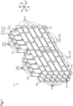
Fig. 1 is a perspective view schematically showing a fiber structure according to a first embodiment. -
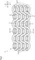
Fig. 2 is a plan view schematically showing the fiber structure ofFig. 1 . -
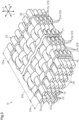
Fig. 3 is a perspective view schematically showing the fiber structure according to a second embodiment. -
Fig. 4 is a cross-sectional view schematically showing the fiber structure ofFig. 3 . - A fiber structure for a fiber-reinforced composite material according to a first embodiment will now be described with reference to
Figs. 1 and2 . The fiber structure for the fiber-reinforced composite material is a fiber structure used in a fiber-reinforced composite material. The fiber-reinforced composite material is formed by combining the fiber structure with a matrix (not shown). The fiber structure is a reinforcing base for the fiber-reinforced composite material. The matrix is, for example, a thermosetting epoxy resin. Hereinafter, the fiber structure for the fiber-reinforced composite material will be simply referred to as the fiber structure. - As shown in
Fig. 1 , thefiber structure 10 includes alaminate 20 andselvage yarns 40. - The
laminate 20 includeswarp yarn layers 21 andweft yarn layers 22. Thefiber structure 10 of the present embodiment includes threewarp yarn layers 21 and threeweft yarn layers 22. Thelaminate 20 is formed by laminating thewarp yarn layers 21 and theweft yarn layers 22. The direction in which thewarp yarn layers 21 and theweft yarn layers 22 are laminated is referred to as the laminating direction Z. The laminating direction Z is orthogonal to a first direction X and a second direction Y, both of which will be described later. - Each
warp yarn layer 21 includeswarp yarns 23. Thewarp yarns 23 extend in the first direction X. Thewarp yarns 23 are arranged in the second direction Y, which is orthogonal to the first direction X. That is, eachwarp yarn layer 21 is formed by arranging, in the second direction Y, thewarp yarns 23 extending in the first direction X. - In the present embodiment, of the three
warp yarn layers 21, twowarp yarn layers 21 are firstwarp yarn layers 21a, and onewarp yarn layer 21 is a secondwarp yarn layer 21b. Each firstwarp yarn layer 21a is formed by arrangingfirst warp yarns 23a, which are thewarp yarns 23 extending in the first direction X, in the second direction Y. The secondwarp yarn layer 21b is formed by arrangingsecond warp yarns 23b, which are thewarp yarns 23 extending in the first direction X, in the second direction Y. The first warp yarns 23a and thesecond warp yarns 23b are alternately arranged in the second direction Y. Thewarp yarns 23 located at the opposite ends in the second direction Y are thefirst warp yarns 23a. - Each
first warp yarn 23a is a reinforcing fiber yarn. The reinforcing fiber in the present embodiment is carbon fiber. Eachsecond warp yarn 23b is made of phenoxy resin. Thefirst warp yarn 23a and thesecond warp yarn 23b are continuous yarns formed by bundling continuous fibers. Thesecond warp yarn 23b is thinner than thefirst warp yarn 23a. Thefirst warp yarn 23a extends straight in the first direction X. Thesecond warp yarn 23b extends in the first direction X while meandering in the laminating direction Z. The structure of thesecond warp yarn 23b will be described in detail later. - Each
weft yarn layer 22 includesweft yarns 24. Theweft yarns 24 extend straight in the second direction Y. Theweft yarns 24 are arranged in the first direction X. That is, eachweft yarn layer 22 is formed by arranging, in the first direction X, theweft yarns 24 extending in the second direction Y. The opposite end sections of theweft yarn layer 22 in the second direction Y protrude outward from thewarp yarns 23 located at the opposite ends in the second direction Y, respectively. Eachweft yarn 24 is a reinforcing fiber yarn. The reinforcing fiber in the present embodiment is carbon fiber. - The laminate 20 includes two
end sections 20a and ageneral section 20b. - The
end sections 20a are located at the opposite ends of the laminate 20 in the second direction Y, respectively. Specifically, the twoend sections 20a are located outward from thewarp yarns 23 located at the opposite ends in the second direction Y, respectively. Eachend section 20a includes multiple weft yarn layers 22 arranged in the laminating direction Z. Specifically, the twoend sections 20a are formed by laminating, in the laminating direction Z, the opposite end sections of the weft yarn layers 22 in the second direction Y. - The
weft yarns 24 of the weft yarn layers 22 located at the opposite ends in the laminating direction Z are spun yarns formed by bundling discontinuous fibers. Theweft yarns 24 of theweft yarn layer 22, other than those located at the opposite ends in the laminating direction Z, are continuous yarns. In the present embodiment, theweft yarn layer 22, other than those located at the opposite ends in the laminating direction Z, refer to oneweft yarn layer 22 positioned between the weft yarn layers 22 located at the opposite ends in the laminating direction Z. - The
general section 20b is located between the twoend sections 20a in the second direction Y. Thegeneral section 20b includes multiple warp yarn layers 21 and multiple weft yarn layers 22, which are arranged in the laminating direction Z. In thegeneral section 20b, the firstwarp yarn layers 21a and the weft yarn layers 22 are alternately laminated in the laminating direction Z. Each firstwarp yarn layer 21a is located between the weft yarn layers 22 in the laminating direction Z. In thegeneral section 20b, the second warp yarn layers 21b are laminated on the weft yarn layers 22 at the opposite ends in the laminating direction Z. - As shown in
Fig. 2 , eachsecond warp yarn 23b includes first warpyarn engagement portions 31, second warpyarn engagement portions 32, and warpyarn connection portions 33. - Each first warp
yarn engagement portion 31 engages with theweft yarns 24 of theweft yarn layer 22 at a first end in the laminating direction Z. The first warpyarn engagement portion 31 is formed by folding back thesecond warp yarn 23b such that it passes outside theweft yarns 24 of theweft yarn layer 22 located at the first end in the laminating direction Z. The first warpyarn engagement portion 31 is laminated on theweft yarns 24 of theweft yarn layer 22 located at the first end in the laminating direction Z. In the present embodiment, the first warpyarn engagement portion 31 is engaged with twoweft yarns 24 of theweft yarn layer 22 located at the first end in the laminating direction Z. - Each second warp
yarn engagement portion 32 engages with theweft yarns 24 of theweft yarn layer 22 located at a second end, which is opposite to the first end, in the laminating direction Z. However, the second warpyarn engagement portion 32 engages withweft yarns 24 that are adjacent, in the first direction X, to theweft yarns 24 with which the first warpyarn engagement portion 31 are engaged. The second warpyarn engagement portion 32 is formed by folding back thesecond warp yarns 23b such that it passes outside theweft yarns 24 of theweft yarn layer 22 located at the second end in the laminating direction Z. The second warpyarn engagement portion 32 is laminated on theweft yarns 24 of theweft yarn layer 22 located at the second end in the laminating direction Z. In the present embodiment, the second warpyarn engagement portion 32 is engaged with twoweft yarns 24 of theweft yarn layer 22 located at the second end in the laminating direction Z. - Each warp
yarn connection portion 33 connects the first warpyarn engagement portion 31 to the second warpyarn engagement portion 32. The warpyarn connection portion 33 extends in the laminating direction Z between theweft yarns 24 with which the first warpyarn engagement portion 31 is engaged and theweft yarns 24 with which the second warpyarn engagement portion 32 is engaged. - In the
second warp yarn 23b, the first warpyarn engagement portion 31 and the second warpyarn engagement portion 32 are alternately and repeatedly provided via the warpyarn connection portion 33. Thesecond warp yarn 23b is alternately engaged with theweft yarn 24 of theweft yarn layer 22 located at the first end in the laminating direction Z and theweft yarn 24 of theweft yarn layer 22 located at the second end in the laminating direction Z. In the present embodiment, thesecond warp yarn 23b is alternately engaged with twoweft yarns 24 of theweft yarn layer 22 located at the first end in the laminating direction Z and twoweft yarns 24 of theweft yarn layer 22 located at the second end in the laminating direction Z. - Two
second warp yarns 23b adjacent to each other, with onefirst warp yarn 23a in between, in the second direction Y are each passed through a different route and engaged with theweft yarns 24 of the weft yarn layers 22 located at the opposite ends in the laminating direction Z. Specifically, the first warpyarn engagement portion 31 of one of thesecond warp yarns 23b and the second warpyarn engagement portion 32 of the othersecond warp yarn 23b are arranged side by side in the second direction Y. Further, the second warpyarn engagement portion 32 of one of thesecond warp yarns 23b and the first warpyarn engagement portion 31 of the othersecond warp yarn 23b are arranged side by side in the second direction Y. The first warpyarn engagement portion 31 of onesecond warp yarn 23b and the first warpyarn engagement portion 31 of the othersecond warp yarn 23b are shifted from each other in the first direction X. The second warpyarn engagement portion 32 of onesecond warp yarn 23b and the second warpyarn engagement portion 32 of the othersecond warp yarn 23b are shifted from each other in the first direction X. - The
second warp yarns 23b are binding yarns that bind the warp yarn layers 21 to the weft yarn layers 22 by engaging with theweft yarns 24 of the weft yarn layers 22 located at the opposite ends in the laminating direction Z. Thus, in the present embodiment, some of thewarp yarns 23 are binding yarns that bind thewarp yarn layer 21 to theweft yarn layer 22 by engaging with theweft yarns 24 in thegeneral section 20b. Theweft yarns 24 with which thesecond warp yarn 23b engages in thegeneral section 20b are theweft yarns 24 of theweft yarn layer 22 located at the opposite ends in the laminating direction Z. Thus, theweft yarn 24 with which thesecond warp yarn 23b engages is a spun yarn. Further, as mentioned above, thesecond warp yarn 23b is a continuous yarn. Therefore, the binding yarn that engages with theweft yarn 24, which is a spun yarn, is a continuous yarn. - Two
selvage yarns 40 are provided at eachend section 20a of the laminate 20. Eachselvage yarn 40 is located outward from thegeneral section 20b in the second direction Y. Theselvage yarn 40 extends in the first direction X while meandering in the laminating direction Z. Theselvage yarn 40 is made of phenoxy resin. Theselvage yarn 40 is a continuous yarn. Theselvage yarn 40 is thinner than thefirst warp yarn 23a. - The
selvage yarn 40 includes first selvageyarn engagement portions 41, second selvageyarn engagement portions 42, and selvageyarn connection portions 43. - Each first selvage
yarn engagement portion 41 engages with theweft yarn 24 of theweft yarn layer 22 located at the first end in the laminating direction Z. The first selvageyarn engagement portion 41 is formed by folding back theselvage yarn 40 such that it passes outside theweft yarn 24 of theweft yarn layer 22 located at the first end in the laminating direction Z. In the present embodiment, the first selvageyarn engagement portion 41 is engaged with oneweft yarn 24 of theweft yarn layer 22 located at the first end in the laminating direction Z. - Each second selvage
yarn engagement portion 42 engages with theweft yarn 24 of theweft yarn layer 22 located at the second end in the laminating direction Z. However, the second selvageyarn engagement portion 42 engages with aweft yarn 24 that is adjacent, in the first direction X, to theweft yarn 24 with which the first selvageyarn engagement portion 41 is engaged. The second selvageyarn engagement portion 42 is formed by folding back theselvage yarn 40 such that it passes outside theweft yarn 24 of theweft yarn layer 22 located at the second end in the laminating direction Z. In the present embodiment, the second selvageyarn engagement portion 42 is engaged with oneweft yarn 24 of theweft yarn layer 22 located at the second end in the laminating direction Z. - The selvage
yarn connection portion 43 connects the first selvageyarn engagement portion 41 to the second selvageyarn engagement portion 42. The selvageyarn connection portion 43 extends in the laminating direction Z between theweft yarn 24 with which the first selvageyarn engagement portion 41 is engaged and theweft yarn 24 with which the second selvageyarn engagement portion 42 is engaged. - In the
selvage yarn 40, the first selvageyarn engagement portion 41 and the second selvageyarn engagement portion 42 are alternately and repeatedly provided via the selvageyarn connection portion 43. Theselvage yarn 40 is alternately engaged with theweft yarn 24 of theweft yarn layer 22 located at the first end in the laminating direction Z and theweft yarn 24 of theweft yarn layer 22 located at the second end in the laminating direction Z. In the present embodiment, theselvage yarn 40 is alternately engaged with eachweft yarn 24 of theweft yarn layer 22 located at the first end in the laminating direction Z and eachweft yarn 24 of theweft yarn layer 22 located at the second end in the laminating direction Z. - The two
selvage yarns 40, which are located at eachend section 20a, are each passed through a different route and engaged with theweft yarns 24 of the weft yarn layers 22 at the opposite ends in the laminating direction Z. In detail, the first selvageyarn engagement portion 41 of oneselvage yarn 40 and the second selvageyarn engagement portion 42 of theother selvage yarn 40 are arranged side by side in the second direction Y. Further, the second selvageyarn engagement portion 42 of oneselvage yarn 40 and the first selvageyarn engagement portion 41 of theother selvage yarn 40 are arranged side by side in the second direction Y. The first selvageyarn engagement portion 41 of oneselvage yarn 40 and the first selvageyarn engagement portion 41 of theother selvage yarn 40 are shifted from each other in the first direction X. The second selvageyarn engagement portion 42 of oneselvage yarn 40 and the second selvageyarn engagement portion 42 of theother selvage yarn 40 are shifted from each other in the first direction X. - Operation and Advantage of Present Embodiment
- The operation and advantages of the present embodiment will now be described.
- (1) At the
end sections 20a of the laminate 20, theselvage yarns 40 are engaged with theweft yarns 24 of the weft yarn layers 22 located at the opposite ends in the laminating direction Z. Theselvage yarns 40 are continuous yarns. Theweft yarns 24 of the weft yarn layers 22 at the opposite ends in the laminating direction Z are spun yarns. The surface coefficient of friction of a spun yarn is greater than that of a continuous yarn. As a result, theselvage yarn 40 is less prone to slipping against theweft yarns 24 of the weft yarn layers 22 located at the opposite ends in the laminating direction Z. This limits the shifting of theselvage yarns 40 in the second direction Y. Consequently, fraying is less likely to occur at the opposite end sections of thefiber structure 10 in the second direction Y. - (2) Among the
warp yarns 23, thesecond warp yarns 23b are binding yarns that engage with theweft yarns 24, which are spun yarns. Thesecond warp yarns 23b are continuous yarns. Thus, compared to when thesecond warp yarns 23b are spun yarns, the strength of the fiber-reinforced composite material is improved. - For example, there may be a case in which the
selvage yarns 40 are spun yarns and theweft yarns 24 of the weft yarn layers 22 at the opposite ends in the laminating direction Z are continuous yarns. In this case, although theselvage yarns 40 are less prone to slipping against theweft yarns 24, thesecond warp yarns 23b, which are continuous yarns, are more prone to slipping against theweft yarns 24. In the present embodiment, theselvage yarns 40 are continuous yarns, and theweft yarns 24 of the weft yarn layers 22 at the opposite ends in the laminating direction Z are spun yarns. As a result, not only are theselvage yarns 40 less prone to slipping against theweft yarns 24, but thesecond warp yarns 23b are also less prone to slipping. Accordingly, not only is the shifting of theselvage yarns 40 in the second direction Y limited, but the shifting of thesecond warp yarns 23b in the second direction Y is also limited. - (3) Among multiple weft yarn layers 22, the
weft yarns 24 of the weft yarn layers 22 at the opposite ends in the laminating direction Z are spun yarns, and theweft yarns 24 of the otherweft yarn layer 22 are continuous yarns. That is, among multiple weft yarn layers 22, theweft yarns 24 of theweft yarn layer 22 other than those at the opposite ends in the laminating direction Z are continuous yarns. Thus, compared to when theweft yarns 24 of theweft yarn layer 22 other than those at the opposite ends in the laminating direction Z are also spun yarns, the strength of the fiber-reinforced composite material is improved. - (4) The
selvage yarn 40 is alternately engaged with eachweft yarn 24 of theweft yarn layer 22 located at the first end in the laminating direction Z and eachweft yarn 24 of theweft yarn layer 22 located at the second end in the laminating direction Z. Thus, as compared to when theselvage yarn 40 is alternately engaged withmultiple weft yarns 24 of theweft yarn layer 22 located at the first end in the laminating direction Z andmultiple weft yarns 24 of theweft yarn layer 22 located at the second end in the laminating direction Z, theselvage yarn 40 is less likely to be shifted. - The fiber structure for the fiber-reinforced composite material according to a second embodiment will now be described with reference to
Figs. 3 and4 . In the second embodiment, the structure of thewarp yarn layer 21 mainly differs from that in the first embodiment. The components that are the same as those in the first embodiment will not be described. - As shown in
Figs 3 and4 , thelaminate 20 of the present embodiment is formed by laminating four warp yarn layers 21 and six weft yarn layers 22 in the laminating direction Z. - Each
warp yarn layer 21 of the present embodiment includes first bindingwarp yarns 23c, which arewarp yarns 23, and secondbinding warp yarns 23d, which are alsowarp yarns 23. The firstbinding warp yarns 23c and the secondbinding warp yarns 23d extend in the first direction X. The firstbinding warp yarns 23c and the secondbinding warp yarns 23d are alternately arranged in the second direction Y. That is, thewarp yarn layer 21 is formed by alternately arranging, in the second direction Y, the firstbinding warp yarns 23c and the secondbinding warp yarns 23d, which extend in the first direction X. In the present embodiment, thewarp yarns 23 at the opposite ends in the second direction Y are the firstbinding warp yarns 23c. - The first
binding warp yarns 23c and the secondbinding warp yarns 23d are fiber-reinforced yarns. The reinforcing fiber in the present embodiment is carbon fiber. Additionally, the firstbinding warp yarns 23c and the secondbinding warp yarns 23d are continuous yarns. - The first
binding warp yarns 23c are engaged with theweft yarns 24 of oneweft yarn layer 22. In detail, the firstbinding warp yarns 23c are engaged with theweft yarns 24, which are arranged in the first direction X to form oneweft yarn layer 22, by alternately passing through one side and the other side of theweft yarns 24 in the laminating direction Z relative to theweft yarns 24. The firstbinding warp yarns 23 are binding yarns that bind thewarp yarn layer 21 to theweft yarn layer 22 by engaging with theweft yarns 24 in thegeneral section 20b. - The second
binding warp yarns 23d are engaged with theweft yarns 24 of two weft yarn layers 22 on the opposite sides in the laminating direction Z of the weft yarn layers 22 with which the firstbinding warp yarns 23c are engaged. Specifically, the secondbinding warp yarns 23d are engaged with theweft yarns 24 by alternately passing through the outer side of theweft yarns 24 of theweft yarn layer 22 on one side in the laminating direction Z relative to theweft yarn layer 22 with which the firstbinding warp yarns 23c are engaged and through the outer side of theweft yarns 24 of theweft yarn layer 22 on the other side in the laminating direction relative to theweft yarn layer 22 with which the firstbinding warp yarns 23c are engaged. The secondbinding warp yarns 23d are binding yarns that bind thewarp yarn layer 21 to theweft yarn layer 22 by engaging with theweft yarns 24 in thegeneral section 20b. Thus, in the present embodiment, all thewarp yarns 23 are binding yarns that bind thewarp yarn layer 21 to theweft yarn layer 22. - Some of the
weft yarns 24 with which thewarp yarns 23 engage in thegeneral section 20b are theweft yarns 24 of theweft yarn layer 22 located at the opposite ends in the laminating direction Z. Thus, some of theweft yarns 24 with which thesecond warp yarns 23b engage are spun yarns. As described above, thewarp yarns 23 are continuous yarns. Therefore, the binding yarn that engages with theweft yarn 24, which is a spun yarn, is a continuous yarn. - As described in the first embodiment, each
weft yarn layer 22 is formed by arranging, in the first direction X,multiple weft yarns 24 extending the second direction Y. In the present embodiment, the number ofweft yarns 24 in theweft yarn layer 22 at the opposite ends in the laminating direction Z is smaller than that ofweft yarns 24 in the four weft yarn layers 22 located between the weft yarn layers 22 at the opposite ends in the laminating direction Z. Theweft yarns 24 of the weft yarn layers 22 at the opposite ends in the laminating direction Z are arranged such that, in the first direction X, each of them overlaps in the laminating direction Z with everyother weft yarn 24 of theweft yarn layer 22 located between the weft yarn layers 22 located at the opposite ends in the laminating direction Z. - The second embodiment achieves the same advantages as the advantages (1) to (4) of the first embodiment.
- Each of the above-described embodiments may be modified as follows. The above-described embodiments and the following modifications can be combined as long as the combined modifications remain technically consistent with each other.
- Reinforcing fibers are not limited to carbon fibers. Examples of the reinforcing fibers may include glass fibers, silicon carbide-based ceramic fibers, aramid fibers, and ultra-high molecular weight polyethylene fibers.
- In the first embodiment, the number of the weft yarn layers 22 is not limited to three. The number of weft yarn layers 22 may be changed as long as there are two or more layers. The number of the first
warp yarn layers 21a is not limited to two. The number of firstwarp yarn layers 21a may be changed. However, the firstwarp yarn layer 21a needs to be located between the weft yarn layers 22 in the laminating direction Z. Two or more firstwarp yarn layers 21a may be arranged between adjacent ones of the weft yarn layers 22 in the laminating direction Z. - In the first embodiment, the
first warp yarn 23a is not limited to a reinforcing fiber yarn. Thefirst warp yarn 23a may be, for example, a yarn made of phenoxy resin or nylon. Thesecond warp yarn 23b does not have to be made of phenoxy. Thesecond warp yarn 23b may be, for example, a yarn made of nylon or a reinforcing fiber yarn. When thefirst warp yarn 23a and thesecond warp yarn 23b are not reinforcing fiber yarns, thefiber structure 10 is a unidirectional fiber structure for a fiber-reinforced composite material that is reinforced only in the second direction Y by theweft yarns 24, which are reinforcing fibers. - In the first embodiment, the
first warp yarn 23a may be a spun yarn. - In the first embodiment, the
second warp yarn 23b may be a spun yarn. - In the first embodiment, the
second warp yarn 23b may be alternately engaged with eachweft yarn 24 of theweft yarn layer 22 located at the first end in the laminating direction Z and eachweft yarn 24 of theweft yarn layer 22 located at the second end in the laminating direction Z. Thesecond warp yarn 23b may be alternately engaged with threeweft yarns 24 of theweft yarn layer 22 located at the first end in the laminating direction Z and threeweft yarns 24 of theweft yarn layer 22 located at the second end in the laminating direction Z. - In the first embodiment, two
second warp yarns 23b that engage with theweft yarns 24 by each passing through a different route may be arranged between adjacent ones of thefirst warp yarns 23a in the second direction Y. - In the second embodiment, the number of weft yarn layers 22 is not limited to six. The number of weft yarn layers 22 may be changed as long as there are two or more layers. The number of warp yarn layers 21 is not limited to four. The number of warp yarn layers 21 may be changed within the range where the
warp yarns 23 can bind the warp yarn layers 21 to the weft yarn layers 22. - In the second embodiment, the
warp yarn 23 is not limited to a reinforcing fiber yarn. Thewarp yarn 23 may be, for example, a yarn made of phenoxy resin or nylon. In this case, thefiber structure 10 is a unidirectional fiber structure for a fiber-reinforced composite material that is reinforced only in the second direction Y by theweft yarns 24, which are reinforcing fiber yarns. - In the second embodiment, the
warp yarn 23 may be a spun yarn. - In the second embodiment, the
warp yarns 23 at the opposite ends in the second direction Y may be the secondbinding warp yarns 23d. Thewarp yarns 23 at one end in the second direction Y may be the firstbinding warp yarns 23c, and thewarp yarns 23 at the other end in the second direction Y may be the secondbinding warp yarns 23d. - In each embodiment, the
weft yarns 24 of the weft yarn layers 22, except for the weft yarn layers 22 at the opposite ends in the laminating direction Z, may also be spun yarns. - In each embodiment, the
selvage yarn 40 may be made of material other than phenoxy. Theselvage yarn 40 may be, for example, a nylon yarn or a reinforcing fiber yarn. - In each embodiment, the
selvage yarn 40 may be engaged only with theweft yarns 24 of theweft yarn layer 22 at the first end in the laminating direction Z. In this case, theselvage yarn 40 is not engaged with theweft yarns 24 of theweft yarn layer 22 at the second end in the laminating direction Z, as it is folded back at an intermediate point in the laminating direction Z. As another example, theselvage yarn 40 may be engaged only with theweft yarns 24 of theweft yarn layer 22 at the second end in the laminating direction Z. In this case, theselvage yarn 40 is not engaged with theweft yarns 24 of theweft yarn layer 22 at the first end in the laminating direction Z, as it is folded back at an intermediate point in the laminating direction Z. In other words, it is sufficient for theselvage yarn 40 to be engaged with theweft yarn 24 of theweft yarn layer 22 located at at least one end in the laminating direction Z. The phrase "at least one end in the laminating direction" refers to either only one end, only the other end, or the opposite ends in the laminating direction. - In each embodiment, the
selvage yarn 40 does not have to be alternately engaged with eachweft yarn 24 of theweft yarn layer 22 located at the first end in the laminating direction Z and eachweft yarn 24 of theweft yarn layer 22 located at the second end in the laminating direction Z. Instead, theselvage yarn 40 may be alternately engaged withmultiple weft yarns 24 of theweft yarn layer 22 located at the first end in the laminating direction Z andmultiple weft yarns 24 of theweft yarn layer 22 located at the second end in the laminating direction Z. - The matrix is not limited to epoxy resin. The matrix may be another thermosetting resin such as vinyl ester resin, unsaturated polyester resin, or phenolic resin. Alternatively, the matrix may be a thermoplastic resin such as polyamide, polybutylene terephthalate, polycarbonate, polyethylene, polypropylene, polyimide resin, or ABS resin.
Claims (4)
- A fiber structure for a fiber-reinforced composite material, the fiber structure comprising:a laminate including at least one warp yarn layer and at least two weft yarn layers, wherein the warp yarn layer includes warp yarns extending in a first direction, the warp yarns are arranged in a second direction that is orthogonal to the first direction, each of the weft yarn layers includes weft yarns that are reinforcing fiber yarns extending in the second direction, the weft yarns are arranged in the first direction, the warp yarn layer and the weft yarn layers are laminated in a laminating direction that is orthogonal to the first direction and the second direction, the laminate includes end sections that are respectively located at opposite ends in the second direction and formed by the weft yarn layers and a general section located between the end sections in the second direction; anda selvage yarn that engages with the weft yarns of the weft yarn layer located at at least one of opposite ends in the laminating direction, whereinat least some of the warp yarns are binding yarns that bind the warp yarn layer to the weft yarn layer by engaging with the weft yarns in the general section,the selvage yarn is a continuous yarn, andthe weft yarns of the weft yarn layers located at the opposite ends in the laminating direction are spun yarns.
- The fiber structure for the fiber-reinforced composite material according to claim 1, wherein
the binding yarns that engage with the weft yarns are continuous yarns, the weft yarns being spun yarns. - The fiber structure for the fiber-reinforced composite material according to claim 1 or 2, wherein
the weft yarns of the weft yarn layer, other than the weft yarn layers located at the opposite ends, in the laminating direction, are continuous yarns. - The fiber structure for the fiber-reinforced composite material according to claim 3, wherein
the selvage yarn is alternately engaged with each of the weft yarns of the weft yarn layer located at one of the opposite ends in the laminating direction and each of the weft yarns of the weft yarn layer located at the other one of the opposite ends in the laminating direction.
Applications Claiming Priority (2)
| Application Number | Priority Date | Filing Date | Title |
|---|---|---|---|
| JP2022104829A JP7718336B2 (en) | 2022-06-29 | 2022-06-29 | Fiber structures for fiber-reinforced composites |
| PCT/JP2023/020778 WO2024004533A1 (en) | 2022-06-29 | 2023-06-05 | Fiber structure for fiber-reinforced composite material |
Publications (2)
| Publication Number | Publication Date |
|---|---|
| EP4549640A1 true EP4549640A1 (en) | 2025-05-07 |
| EP4549640A4 EP4549640A4 (en) | 2025-10-01 |
Family
ID=89382733
Family Applications (1)
| Application Number | Title | Priority Date | Filing Date |
|---|---|---|---|
| EP23830983.5A Pending EP4549640A4 (en) | 2022-06-29 | 2023-06-05 | FIBER STRUCTURE FOR FIBER REINFORCED COMPOSITE |
Country Status (5)
| Country | Link |
|---|---|
| US (1) | US20250179696A1 (en) |
| EP (1) | EP4549640A4 (en) |
| JP (1) | JP7718336B2 (en) |
| CA (1) | CA3258729A1 (en) |
| WO (1) | WO2024004533A1 (en) |
Family Cites Families (7)
| Publication number | Priority date | Publication date | Assignee | Title |
|---|---|---|---|---|
| JP3226330B2 (en) * | 1992-06-18 | 2001-11-05 | 株式会社アイ・エイチ・アイ・エアロスペース | Woven fabric and prepreg for tape wrap molding |
| JP2006144847A (en) * | 2004-11-17 | 2006-06-08 | Bando Chem Ind Ltd | Resin belt |
| JP6790967B2 (en) * | 2017-03-31 | 2020-11-25 | 株式会社豊田自動織機 | Fiber structure and fiber reinforced composite |
| JP6855889B2 (en) | 2017-04-11 | 2021-04-07 | 株式会社豊田自動織機 | Method for manufacturing fiber structure and fiber reinforced composite material |
| JP2019094578A (en) * | 2017-11-17 | 2019-06-20 | 株式会社豊田自動織機 | Fiber structure and fiber reinforced composite material |
| JP2020179705A (en) * | 2019-04-23 | 2020-11-05 | 株式会社豊田自動織機 | Structural material |
| JP7287162B2 (en) * | 2019-07-19 | 2023-06-06 | 株式会社豊田自動織機 | Fiber structures and fiber reinforced composites |
-
2022
- 2022-06-29 JP JP2022104829A patent/JP7718336B2/en active Active
-
2023
- 2023-06-05 WO PCT/JP2023/020778 patent/WO2024004533A1/en not_active Ceased
- 2023-06-05 EP EP23830983.5A patent/EP4549640A4/en active Pending
- 2023-06-05 US US18/875,997 patent/US20250179696A1/en active Pending
- 2023-06-05 CA CA3258729A patent/CA3258729A1/en active Pending
Also Published As
| Publication number | Publication date |
|---|---|
| WO2024004533A1 (en) | 2024-01-04 |
| CA3258729A1 (en) | 2025-04-07 |
| US20250179696A1 (en) | 2025-06-05 |
| EP4549640A4 (en) | 2025-10-01 |
| JP2024004923A (en) | 2024-01-17 |
| JP7718336B2 (en) | 2025-08-05 |
Similar Documents
| Publication | Publication Date | Title |
|---|---|---|
| JP2022182789A (en) | Fiber structure, and fiber-reinforced composite material | |
| JP2011074207A (en) | Preform of fiber reinforced composite material and method for producing the same | |
| EP3604649A1 (en) | Fibrous structure and fiber-reinforced composite material | |
| US20250179696A1 (en) | Fiber structure for fiber-reinforced composite material | |
| EP3712309A1 (en) | Fiber construct, fiber-reinforced composite material, and method for manufacturing these | |
| CN108431314B (en) | Fabrics and fiber-reinforced composites for fiber-reinforced composites | |
| WO2016035694A1 (en) | Energy-absorbing member | |
| EP4512946A1 (en) | Fiber structure and fiber-reinforced composite material | |
| JP5644755B2 (en) | Textile substrate and fiber reinforced composite material | |
| JP7666397B2 (en) | Fiber structure for fiber-reinforced composite material and fiber-reinforced composite material | |
| EP3581690A1 (en) | Fiber structure and fiber reinforced composite material | |
| JP7609009B2 (en) | Fiber structures and fiber-reinforced composites | |
| JP7287162B2 (en) | Fiber structures and fiber reinforced composites | |
| EP3375920B1 (en) | Fiber structure | |
| EP3604648A1 (en) | Fibrous structure and fiber-reinforced composite material | |
| JP2022119368A (en) | Fiber structure and fiber-reinforced composite material | |
| WO2013035518A1 (en) | Woven fabric base material and fiber-reinforced composite material | |
| JP2026000064A (en) | Fiber structures and fiber-reinforced composites | |
| JP2025173417A (en) | Fiber structures and fiber-reinforced composites | |
| JP5550827B2 (en) | FRP drawn structure member and manufacturing method thereof | |
| JP2022098319A (en) | Fiber structure and fiber reinforced composite | |
| JP2014004735A (en) | Fiber-reinforced composite material and method of producing fiber-reinforced composite material | |
| JP4069202B2 (en) | Method for producing three-dimensional fiber reinforced composite lugs | |
| JP2022122656A (en) | Fiber structure, fiber-reinforced composite material, and fiber structure manufacturing method | |
| JP2015098156A (en) | Three-dimensional fiber-reinforced composite material |
Legal Events
| Date | Code | Title | Description |
|---|---|---|---|
| STAA | Information on the status of an ep patent application or granted ep patent |
Free format text: STATUS: THE INTERNATIONAL PUBLICATION HAS BEEN MADE |
|
| PUAI | Public reference made under article 153(3) epc to a published international application that has entered the european phase |
Free format text: ORIGINAL CODE: 0009012 |
|
| STAA | Information on the status of an ep patent application or granted ep patent |
Free format text: STATUS: REQUEST FOR EXAMINATION WAS MADE |
|
| 17P | Request for examination filed |
Effective date: 20241203 |
|
| AK | Designated contracting states |
Kind code of ref document: A1 Designated state(s): AL AT BE BG CH CY CZ DE DK EE ES FI FR GB GR HR HU IE IS IT LI LT LU LV MC ME MK MT NL NO PL PT RO RS SE SI SK SM TR |
|
| A4 | Supplementary search report drawn up and despatched |
Effective date: 20250901 |
|
| RIC1 | Information provided on ipc code assigned before grant |
Ipc: D03D 1/00 20060101AFI20250826BHEP Ipc: D03D 5/00 20060101ALI20250826BHEP Ipc: D03D 11/00 20060101ALI20250826BHEP |
|
| DAV | Request for validation of the european patent (deleted) | ||
| DAX | Request for extension of the european patent (deleted) |