EP4549333A1 - Blank and a package - Google Patents
Blank and a package Download PDFInfo
- Publication number
- EP4549333A1 EP4549333A1 EP24208858.1A EP24208858A EP4549333A1 EP 4549333 A1 EP4549333 A1 EP 4549333A1 EP 24208858 A EP24208858 A EP 24208858A EP 4549333 A1 EP4549333 A1 EP 4549333A1
- Authority
- EP
- European Patent Office
- Prior art keywords
- bottom panel
- polymer
- blank
- based film
- paper
- Prior art date
- Legal status (The legal status is an assumption and is not a legal conclusion. Google has not performed a legal analysis and makes no representation as to the accuracy of the status listed.)
- Pending
Links
Images




Classifications
-
- B—PERFORMING OPERATIONS; TRANSPORTING
- B65—CONVEYING; PACKING; STORING; HANDLING THIN OR FILAMENTARY MATERIAL
- B65D—CONTAINERS FOR STORAGE OR TRANSPORT OF ARTICLES OR MATERIALS, e.g. BAGS, BARRELS, BOTTLES, BOXES, CANS, CARTONS, CRATES, DRUMS, JARS, TANKS, HOPPERS, FORWARDING CONTAINERS; ACCESSORIES, CLOSURES, OR FITTINGS THEREFOR; PACKAGING ELEMENTS; PACKAGES
- B65D5/00—Rigid or semi-rigid containers of polygonal cross-section, e.g. boxes, cartons or trays, formed by folding or erecting one or more blanks made of paper
- B65D5/42—Details of containers or of foldable or erectable container blanks
- B65D5/56—Linings or internal coatings, e.g. pre-formed trays provided with a blow- or thermoformed layer
- B65D5/60—Loose, or loosely attached, linings
- B65D5/603—Flexible linings loosely glued to the wall of the container
-
- B—PERFORMING OPERATIONS; TRANSPORTING
- B65—CONVEYING; PACKING; STORING; HANDLING THIN OR FILAMENTARY MATERIAL
- B65D—CONTAINERS FOR STORAGE OR TRANSPORT OF ARTICLES OR MATERIALS, e.g. BAGS, BARRELS, BOTTLES, BOXES, CANS, CARTONS, CRATES, DRUMS, JARS, TANKS, HOPPERS, FORWARDING CONTAINERS; ACCESSORIES, CLOSURES, OR FITTINGS THEREFOR; PACKAGING ELEMENTS; PACKAGES
- B65D5/00—Rigid or semi-rigid containers of polygonal cross-section, e.g. boxes, cartons or trays, formed by folding or erecting one or more blanks made of paper
- B65D5/42—Details of containers or of foldable or erectable container blanks
- B65D5/56—Linings or internal coatings, e.g. pre-formed trays provided with a blow- or thermoformed layer
- B65D5/563—Laminated linings; Coatings
-
- B—PERFORMING OPERATIONS; TRANSPORTING
- B65—CONVEYING; PACKING; STORING; HANDLING THIN OR FILAMENTARY MATERIAL
- B65D—CONTAINERS FOR STORAGE OR TRANSPORT OF ARTICLES OR MATERIALS, e.g. BAGS, BARRELS, BOTTLES, BOXES, CANS, CARTONS, CRATES, DRUMS, JARS, TANKS, HOPPERS, FORWARDING CONTAINERS; ACCESSORIES, CLOSURES, OR FITTINGS THEREFOR; PACKAGING ELEMENTS; PACKAGES
- B65D5/00—Rigid or semi-rigid containers of polygonal cross-section, e.g. boxes, cartons or trays, formed by folding or erecting one or more blanks made of paper
- B65D5/20—Rigid or semi-rigid containers of polygonal cross-section, e.g. boxes, cartons or trays, formed by folding or erecting one or more blanks made of paper by folding-up portions connected to a central panel from all sides to form a container body, e.g. of tray-like form
-
- B—PERFORMING OPERATIONS; TRANSPORTING
- B65—CONVEYING; PACKING; STORING; HANDLING THIN OR FILAMENTARY MATERIAL
- B65D—CONTAINERS FOR STORAGE OR TRANSPORT OF ARTICLES OR MATERIALS, e.g. BAGS, BARRELS, BOTTLES, BOXES, CANS, CARTONS, CRATES, DRUMS, JARS, TANKS, HOPPERS, FORWARDING CONTAINERS; ACCESSORIES, CLOSURES, OR FITTINGS THEREFOR; PACKAGING ELEMENTS; PACKAGES
- B65D5/00—Rigid or semi-rigid containers of polygonal cross-section, e.g. boxes, cartons or trays, formed by folding or erecting one or more blanks made of paper
- B65D5/42—Details of containers or of foldable or erectable container blanks
- B65D5/44—Integral, inserted or attached portions forming internal or external fittings
-
- B—PERFORMING OPERATIONS; TRANSPORTING
- B65—CONVEYING; PACKING; STORING; HANDLING THIN OR FILAMENTARY MATERIAL
- B65D—CONTAINERS FOR STORAGE OR TRANSPORT OF ARTICLES OR MATERIALS, e.g. BAGS, BARRELS, BOTTLES, BOXES, CANS, CARTONS, CRATES, DRUMS, JARS, TANKS, HOPPERS, FORWARDING CONTAINERS; ACCESSORIES, CLOSURES, OR FITTINGS THEREFOR; PACKAGING ELEMENTS; PACKAGES
- B65D81/00—Containers, packaging elements, or packages, for contents presenting particular transport or storage problems, or adapted to be used for non-packaging purposes after removal of contents
- B65D81/24—Adaptations for preventing deterioration or decay of contents; Applications to the container or packaging material of food preservatives, fungicides, pesticides or animal repellants
- B65D81/26—Adaptations for preventing deterioration or decay of contents; Applications to the container or packaging material of food preservatives, fungicides, pesticides or animal repellants with provision for draining away, or absorbing, or removing by ventilation, fluids, e.g. exuded by contents; Applications of corrosion inhibitors or desiccators
- B65D81/261—Adaptations for preventing deterioration or decay of contents; Applications to the container or packaging material of food preservatives, fungicides, pesticides or animal repellants with provision for draining away, or absorbing, or removing by ventilation, fluids, e.g. exuded by contents; Applications of corrosion inhibitors or desiccators for draining or collecting liquids without absorbing them
Definitions
- the invention relates to a blank configured to be folded into a package.
- the invention also relates to a package.
- the package should, e.g., be designed such that it makes efficient use of material, is easy to prepare for use, is space efficient during transport and storage, and provides a strong structure during use. Moreover, it is often desirable that the package should be formed in a manner that requires a limited number of folding operations, and/or folding operations which are easy to perform. When formed, the package should be capable of maintaining its structure when being filled with its intended content. In cases where the intended content of the package is to some extent in liquid form, another design criterion is often added, namely that the package should be leak-proof during normal use.
- a common problem when using leak-proof containers is that, when the intended content is releasing liquid over time, the product may get wet and soggy, and thereby become less aesthetically pleasing and typically also to degrade faster, which results in more products being wasted.
- WO 2007/091004 there is disclosed a container which is formed by folding a blank.
- the resulting container is sealed against spillage of liquid contents.
- This sealing is accomplished by the blank being formed of a paper board blank being coated with a plastic material and by designing the corner portions of the blank with a plurality of triangular corner panels that are folded in an overlapping manner such that tight corners are formed.
- the use of a paperboard coated with a plastic material makes the foldable container difficult to recycle.
- EP 0 442 720 there is disclosed a semi-rigid, lined container with fluted or undulating interior bottom surface.
- the flutes are provided by removing an interior top layer of a corrugated board such that the interior flutes are exposed. It is said that this design increases the adhesion between the bottom layer and a plastic lining and that it provides effective channels for circulating gases such as carbon dioxide, oxygen, or nitrogen around the product, such as a food product.
- removal of the top layer without damaging the flutes is a delicate process, and moreover an increased adhesion between the package and the liner can result in making it more difficult to separate the materials and in turn making recycling more difficult.
- absorbent pads to keep food products, such as e.g., meat or fish, sufficiently dry in a package.
- the absorbent pads usually include several layers of different materials to be able to on one hand absorb the liquid and on the other hand to be able to present a comparably dry surface to the food product.
- These absorbent pads often include absorbing materials which are comparably non environmentally friendly. Even if the pads typically are easy to remove from the package, the recycling of the pads themselves are inherently difficult.
- An object of the invention is to provide a package addressing at least some of the design criteria that the package should make efficient use of material, be easy to prepare for use, be leak proof, keep intended content sufficiently dry, be easy to recycle and provide a strong structure during use.
- a blank configured to be folded into a package, the blank comprising
- the bottom panel insert is located directly or indirectly on top of an interior surface of the bottom panel, which would refer to an interior surface of the package after being folded, such as an inside bottom panel of a package.
- a surface area of the bottom panel insert refers to an area of a major surface of the bottom panel insert, where such a surface area typically is in a plane parallel with the bottom panel.
- the surface area of the bottom panel refers to the surface area of the bottom panel being confined within the plurality of side walls.
- the polymer-based film preferably extends beyond the whole bottom layer such that it covers all of the bottom panel as well as at least parts of some and preferably at least parts of all wall panels. It may further be understood that the polymer base film extending into or being allowed to extend down into at least some and preferably into all of said channels is intended to refer to the that the polymer-based film has an extension sufficient for it to at least partly and preferably fully follow the shape of the channels and extend down into the channels rather than extending across the channels like a drum skin.
- an intended upper portion of respective one of the two side wall panels refers to an upper portion of respective side walls when the blank is folded into a package.
- the polymer-based film may be continuously or intermittently attached along the respective attachment zone.
- the upper portion is preferably at a minimum at least a distance away from the bottom panel that is equal or greater than the thickness of the bottom panel insert such that the polymer-based film is attached at a portion being higher than the upper surface of the insert.
- the side wall panels each has a respective height extension and a respective length extension, wherein the length extension is orthogonal to said respective height extension and wherein the side wall panels are configured to be folded such that the height extension extends upwardly from the bottom.
- the respective attachment zone preferably extends along at least 80%, more preferably along at least 90% of the length extension of the respective one of the two side wall panels. It may in this context be noted that if the plastic sheet is intermittently attached to the side wall panels along the attachment zone, the extension of the attachment zone as seen along the length extension, refers to the distance between the two most distant attachment points as seen along the length extension. Thus, the attachment zone extending along at least 80% and preferably along at least 90% of the length extension does not necessarily refer to the total extension of the actual attachments. The total extension of the actual attachments may be less than said at least 80% or preferably at least 90%, as long as the distance between the two most distant attachment points defines an attachment zone as discussed above. Moreover, it is preferred that the attachment zone extends along the length extension such that there is less than 2cm, preferably less than 1cm distance between the edge of the side wall panel and the outermost point of the attachment zone as seen along the length extension.
- the attachment zone is formed of intermittent attachment points, it is preferred that the actual attachments make up at least 40% of the extension of the attachment zone as seen along the length extension.
- the respective attachment zone has a height extension less than 15mm, preferably less than 10mm, along the height extension of the respective one of the two side wall panels.
- the attachment zone extends along an intended upper portion of the respective one of the two side wall panels.
- the intended upper portion corresponds to the upper most 30% of the side wall panels as seen in a state where the blank has been folded into a package.
- opposing side walls By opposing side walls, it is herein meant side walls that faces in directions having at least a component of the direction extending towards the other side wall.
- the opposing sides may e.g., be directly opposing each other and face directly towards each other as would e.g., be the case in a rectangular package.
- the opposing side walls may alternatively be part of a non-rectangular package and may be directly adjacent each other at a corner or may be non-adjacent with another sidewall therebetween.
- the side walls may e.g., be adjacent each other forming an internal angle of less than 90 degrees. Such a design may e.g., be useful in case of a generally triangular package.
- the side walls may alternatively be non-adjacent and e.g., form an internal angle of greater than 90 degrees. Such a design may e.g., be useful in case of a generally polygon shaped package with four or more side walls.
- the notion of attaching the polymer-based film at least to upper portions of at least two opposing side walls is that the package will be able to hold the polymer-based film such that there is formed a cavity with a bottom and upwardly extending portions of the polymer-based film.
- the package is rectangular, and the polymer-based film is attached to four side wall panels configured to form the four side walls of the package. Also in that case, the polymer-based film is attached at at least a respective attachment zone extending along an intended upper portion of the respective one of the side wall panels.
- An advantage with the invention is that it is made possible to provide a package where the channels are able to hold an amount of liquid.
- the channels By being provided with a bottom panel insert with a smaller surface area than the bottom panel, channels will be created.
- the channels become leak-proof in regard to liquid.
- the bottom panel insert has a thickness, wherein the thickness is the extension of the bottom panel insert orthogonally to the major surface area of the bottom panel insert.
- the thickness may vary at different parts of the surface area.
- a thickness of the bottom panel insert may refer to a thickness along the perimeter of the bottom panel insert.
- the thickness of the bottom panel insert may preferably be greater than 2 mm, preferably greater than 4 mm. It is to be understood that a greater thickness of the bottom panel insert will increase the amount of liquid that can be hold in the channels, given that the surface areas of the bottom panel and the bottom panel insert remain the same.
- a thickness, of the bottom panel insert of at least 2 mm is considered to be suitable to make the channels deep enough to hold a relevant amount of liquid, without having to have an excessively large difference in the surface areas of the bottom panel insert and bottom panel, respectively.
- the bottom panel insert is made of corrugated paper board.
- the bottom layer insert may comprise one or more layer/layers of said paper board/boards.
- the corrugated paper board typically provides a material which is comparably thick and strong, yet light weight.
- the second layer has a thickness, wherein the thickness is the extension of the second layer in the same direction as the thickness of the bottom panel insert.
- the package may be leak-proof.
- a leak proof package will allow liquidous content in the package without damaging the paper-based material of either the first or second layer.
- a leak-proof package is realized by having a polymer-based film positioned on an interior side of the package.
- Another advantage with the invention is that once the blank has been folded into a package, the package is easy to fill.
- the polymer-based film By attaching said polymer-based film to at least two opposing side walls, the polymer-based film will be situated so that it is easy to fill the package without having to manage the polymer-based film at the same time.
- the bottom layer insert may in a sense be said to be self-draining. If the intended content for the package is releasing liquid, but at the same time have to be held relatively dry, such as e.g. fish or meat, the intended content will be supported on top of the bottom layer insert and the liquid will inherently be displaced to different parts of the package by the base not being perfectly flat or by small shifts in angle of the package induced by, for example, transporting or lifting the package. By displacing, at least part of, the liquid it will find its way towards the edges of the bottom panel insert. The liquid at the edges of the bottom panel insert will flow into the channels around the perimeter of the bottom layer insert. By entrapping liquid in the channels, or drain the bottom layer insert, it is understood that at least part of the liquid is not able to be in contact with the intended content, hence a drier product can be obtained.
- the paper-based layers are comparably easily cut using any conventional cutting machine, such as a die cut machine.
- the two paper-based layers may then in a comparably simple process be positioned on top of each other; manually or automatically in a machine.
- the polymer-based film is then positioned on top of the two paper-based layers and is attached to at least two opposing side walls.
- the polymer-based film may e.g., be provided on a roll where a part of the film is rolled out of the roll and stretch out on top of the paper-based layers.
- the polymer-based film may be attached to the paper-based layers by any conventional means.
- the polymer-based film may be attached to the respective paper-based layer using adhesive positioned between the polymer-based film and the respective paper-based layer at certain positions through-out the area of the blank; including said upper portions of the side walls.
- the polymer-based film is attached to the respective paper-based layer using a heat sealing operation, such as a thermo-forming operation, where inherent heat sealing properties of the polymer-based film are utilized to attach the polymer-based film to the respective paper-based layer.
- the polymer-based film may be attached to the respective paper-based layer over the complete common surface area or may be attached to the respective paper-based layer only at select positions.
- the select positions may e.g., be said upper portions of the side wall.
- the select positions may also include all or parts of the bottoms of the channels.
- the polymer-based film being attached only at select positions typically facilitates separation of the polymer-based film from the paper-based layers during recycling.
- the bottom panel insert may be provided with at least one groove in an upper surface thereof with the polymer-based film extending or being allowed to extend down into at least some and preferably into all of said grooves.
- the grooves may also be said to form channels in the upper surface of the insert. The discussion above relating to the channels around the insert is equally applicable to the channels formed by said grooves.
- the groove may be formed by a crease being formed in an upper most layer of the bottom panel insert, and/or by a cut being formed in an upper most layer, or a plurality of upper most layers, of the bottom panel insert.
- the bottom panel insert may e.g., be formed of a corrugated paper material having more than one flute layers.
- a set of cuts may be provided in the uppermost flat layer and through one or more of the uppermost flute layers and the cut layers may be crushed such that the flutes collapse and a distinct groove is formed. This may e.g., be performed in a conventional die cut machine.
- the bottom panel insert may be formed of a plurality of layers of paper-based material being positioned or folded on top of each other such that there is formed grooves. It is e.g., possible to have a rectangular centre panel with triangular flaps extending outwardly.
- the triangular flaps may in total have a slightly smaller size than the centre panel such that as the triangular flaps are folded onto the centre panel, there is formed a diagonal cross of grooves between the triangular flaps.
- the bottom panel insert is provided with a plurality of grooves with the polymer-based film extending, or being allowed to extend, down into at least some, and preferably into all, of said grooves.
- An advantage of the bottom panel insert being provided with a plurality of grooves is that liquid can be guided from more than one location and/or towards more than one location inside the package, and thereby that package's capability of keeping the product from soaking in liquid is improved.
- a depth of at least one of the channels around the perimeter of the bottom panel insert is preferably greater than a depth of a groove in the bottom panel insert.
- An advantage of having a depth of the channel, which is greater than a depth of the groove, is that the liquid will be entrapped in the channels and thereby having a reduced possibility to flow back onto the bottom panel insert.
- the groove or grooves of the bottom panel insert may be connected with at least one of said channels. Connected is in this context intended to refer to a connection allowing liquid to flow from the respective groove to at least a respective one of said channels.
- An advantage of connecting the groove or grooves with the channel or channels is that liquid may be guided or directed towards the channels and therefore it is facilitated to keep the bottom panel dry.
- all grooves have at least one connection to a channel.
- all grooves are directly or indirectly connected to a respective channel at two different sides of the package.
- Different sides is in this context preferably intended to refer to that if the package is tilted slightly in a first direction about an axis extending along a bottom plane, any liquid in the groove or grooves has a tendency to flow into a channel at the first side of the package and if the package is tilted slightly in a second direction, opposite the first direction, about the axis, any liquid in the groove or grooves has a tendency to flow into a channel at the second side of the package.
- the sides do not need to, although they in the preferred embodiment are, directly opposite to each other.
- all the grooves are directly or indirectly connected to a respective channel at all different sides of the package.
- the grooves are directly or indirectly connected to a respective channel at all four different sides of the package.
- the grooves are interconnected such that any tilting about any arbitrary axis extending along a bottom plane will result in that there is a downward slope from all the grooves to one or more channels at the one or more sides being moved downwardly by said tilting. It may be noted that it is not necessary that the channel or channels around the bottom panel insert have a depth being greater than the depth of the groove along the whole extension of the channel or channels. However, in case there is a portion of the channel or channel having a lesser depth, it is preferred that any such shallow portion is located a distance from any connection between the channel and any groove such that there is no immediate tendency of liquid flowing from the shallow portion into a groove.
- the polymer-based film may be a liquid-tight polymer-based film.
- the polymer-based film is preferably a single continuous film, but it may be two or more polymer-based films. If formed of two or more polymer-based films, the films are preferably positioned with an overlap and more preferably with a continuous seal along the overlap such that they functionality act as a single continuous film once positioned and attached to the paper-based layer or layers. It may also be noted that the film may be formed of one or more layers. If formed of several layer, the layers are preferably laminated together into a single film before being attached to the paper-based layers.
- the polymer-based film may have other kinds of barrier properties.
- the polymer-based film may e.g., have oxygen barrier properties and may in such a case e.g., form part of an oxygen barrier enclosure fully and sealingly enclosing the products inside the package.
- the enclosure may be formed of the polymer-based film as such or may be complemented with a lid provided with a barrier film and/or with a top cover formed of a barrier film.
- the polymer-based film may be attached, at least partly, to at least one of said channels. Attached to a channel is intended to refer to the polymer-based film being attached to the side walls and/or bottom of the channel such that the film at least partly follows the cross-sectional shape of the channel. It may be noted that the film does not need to be attached along the complete extension of the channel.
- the film may e.g., be intermittently connected to the channel, such as by attachment areas intermittently provided at the bottom of the channel.
- the channels By having the polymer-based film being attached to a channel, the channels will be present at least partly and available to instantaneously receive a liquid.
- the channel volume will be above the polymer-based film.
- the polymer-based film may be attached, at least partly, to at least one of the grooves. Attached to a groove is intended to refer to the polymer-based film being attached to the side walls and/or bottom of the groove such that the film at least partly follows the cross-sectional shape of the groove. It may be noted that the film does not need to be attached along the complete extension of the groove.
- the film may e.g., be intermittently connected to the groove, such as by attachment areas intermittently provided at the bottom of the groove.
- the groove By having the polymer-based film being attached to a groove, the groove will be present at least partly and available to guide liquid.
- the polymer-based film may be attached to all side walls at at least a respective attachment zone extending along an intended upper portion of the respective side wall panel. It may in this context be noted that all side walls does not necessarily mean that it has to be connected to all side wall panels, especially if there are one or more side wall panels fully or partly hidden behind other side wall panels at a respective side wall. However, it is preferred that the film is attached to an intended inside of at least one side wall panel at each side of the package.
- the bottom panel insert may be positioned such that a channel is formed at at least two opposite sides of the bottom panel insert.
- An advantage of having the bottom panel insert positioned such that a channel is formed at at least two opposite sides of the bottom panel insert is that the availability of channels, for liquid to flow into, is comparably high. Liquid will flow into a channel due to any tilting of the package in more than one direction.
- the bottom panel insert is positioned such that a channel is formed at all sides of the bottom panel insert.
- the package will present a channel capable of receiving liquid independently from in which direction the package is slightly tilted.
- a package formed of a blank comprising:
- the first and second layers of the blank are preferably made of a paper-based material, e.g., a material based on paper or paperboard.
- Paper-based material may provide a lightweight package. Paper-based material may be produced in an environmentally friendly manner and may be recycled in a simple manner. Paper-based material may provide a blank that is easy to transport and handle before the blank is formed to the package. It may be noted that the blank may be made of other materials. It may be noted that the blank as a whole may be made of paper-based material. It may be noted that the blank need not to be made of the same material through-out.
- the blank may be made of a paper-based material coated or laminated with a polymer-based coating, such as a thermoplastic material, on one or both sides thereof. Such coating may be heat-sealable and/or provide a desired tightness, i.e., barrier properties, such as being waterproof, water resistant, grease proof, grease resistant, food safe, etc.
- first, second, third, fourth, fifth, etc. are mainly to be seen as labels facilitating reading and that it does not necessarily mean that there need to be all the intervening numbers of portions present. It may e.g., be noted that in cases where it is contemplated to have a design where there is a first portion, a second portion, a third portion and a fifth portion, with the fourth portion being omitted, there is however, to facilitate reading, a consistent use of the numbering first, second, third, fourth, etc., as labels, and in a sense based on an embodiment including all conceivable portions. It may also be noted that the blank may comprise one or more additional layers of a paper-based material between the first and the second layer discussed above.
- any such optional additional layer or layers may be formed of separate entities sandwiched between the first and the second layers. Any such optional additional layer or layers may alternatively be integrally formed with the second layer.
- the additional layers may e.g., be formed of a layer being foldably connected to the second layer. This may alternatively be expressed as that the bottom layer insert includes several layers which are separate from each other or which are integrally formed and foldably connected to each other.
- the orientations and the position relationship indicated by the terms “top”, “bottom”, “upper” and “lower”, etc. are those based on what are shown in the drawing, or the orientations and the position relationship when the product of the disclosure is commonly placed, which is merely for convenience of the description of the disclosure and of simplifying the description, but does not indicate or imply the device or the element has to be have particular orientation, or to be constructed or operated in an particular orientation, and thus cannot be understood as limiting on the disclosure.
- the detailed description of the embodiment of the disclosure provided in combination with the drawing does not aim to limiting the protection scope of the disclosure, and is only the selected embodiment of the disclosure. Based on the embodiment of the disclosure, all the other embodiments obtained by those skilled in the art without any creative work would belong to the protection scope of the disclosure.
- a blank 10 comprising a first layer 20 of a paper-based material and a second layer of a paper-based material and a polymer-based film 40.
- the first layer comprises a bottom panel 21 and a plurality of side wall panels 22a-d.
- the first layer 20 of paper-based material of the blank 10 is shown in a flat laid state.
- the first layer 20 comprises a rectangular bottom panel 21 and four side walls 22 a-d at a respective side of the bottom panel 21.
- the bottom panel can have any shape.
- the blank 10 has crease lines to guide and facilitate the folding of the blank to a package.
- the bottom panel 21 has a major surface area.
- the four side walls 22 a-d may have different shapes.
- the side walls can be less than or more than four.
- the number of side walls 22 a-d is the same as the number of edges of the bottom panel 21.
- the four side walls 22 a-d are foldably connected to the bottom panel and configured to be folded upwardly.
- the paper-based material is preferably a corrugated board.
- the flute types of the corrugated board may vary from N to C and could also be double walled such as E/B or other suitable combinations as well. This is applicable for any paper-based layer discussed herein.
- a blank 10 comprising the first layer 20 as shown in Fig 1 and the second layer 30 of a paper-based material comprising a bottom panel insert 31.
- the second layer 30 may further comprise additional layers.
- the additional layers may be paper-based or polymer-based, such as being a thin coating on either one, or a plurality of sides such as all sides.
- the bottom panel insert 31 has three grooves 33 extending in three different directions. Alternatively, it may be expressed as that there are six different grooves being pair-wise parallel to each other and all meeting in a central junction. From the context it is understood that there can be no grooves, one groove or a plurality of grooves in the bottom layer insert 31.
- the grooves 33 may vary in width, depth, shape, i.e., being straight or curved, and direction. The width or depth can vary independently of each other along a direction of the grooves 33.
- the grooves may intersect preferably in a central part of the bottom panel insert 31. In an embodiment with several groove 33, the grooves may be non-intersecting.
- the grooves can be formed from creasing, die cutting or any other suitable technique to make grooves in a paper-based material.
- the bottom panel insert is placed on top of an intended interior surface of the bottom panel 21.
- the bottom panel insert 31 may be located directly or indirectly on top of an interior surface of the bottom panel 21.
- the thickness of the bottom layer insert may be more than 2 mm, preferably more than 4 mm
- the material may e.g., be 2-8mm.
- the bottom panel insert 31 has a surface area smaller than a surface area of the bottom panel 21 such that, when the side wall panels 22a-d are folded upwardly relative to the bottom panel 21, one or more channels 23 are formed around at least a part of a perimeter of the bottom panel insert 31.
- at least one channel is formed at each side of the bottom panel insert 31. Even more preferably one continuous channel is formed more or less, preferably completely, around the entirety of the perimeter of the bottom panel insert.
- the depths of the channels are greater than the depth of the grooves.
- the grooves are connected to the channel.
- all grooves are directly or indirectly connected to a channel.
- all channels are connected to at least one groove.
- the blank 10 is provided with a polymer-based film 40 being positioned on top of the first and second paper-based layers.
- the thickness of the polymer-based film 40 is preferably 30-90 ⁇ m, and more preferably 60-90 ⁇ m.
- a polymer-based film of such thickness is typically sufficiently flexible to be easily folded, but still strong enough to allow the polymer-based film to easily be peeled off from the paperboard blank.
- the polymer-based film 40 may e.g., be provided on a roll where a part of the film is rolled out of the roll and stretch out on top of the paper-based layers. It is also conceivable that the polymer-based film 40 is provided in sheets.
- the polymer-based film may be based on polyethylene terephthalate (PET), polyethylene terephthalate glycol modified (PETG), polypropylene (PP), polyethylene (PE), polyamide (PA), or any other suitable polymer.
- PET polyethylene terephthalate
- PET polyethylene terephthalate glycol modified
- PP polypropylene
- PE polyethylene
- PA polyamide
- the polymer-based film 40 extends or is allowed to extend down into at least part of at least one of the channels. It may be noted that the polymer-based film preferably extends beyond the whole bottom layer such that it covers all of the bottom panel as well as at least parts of some and preferably at least parts of all wall panels.
- FIG 4 there is disclosed the blank shown in Fig 3 with the polymer-based film 40 being attached to the side walls 22a-d at a respective attachment zone 42 extending along an intended upper portion of the respective side wall panels 22a-d.
- "upper" in terms of the attachment zone 42 refers to upper portions of a folded package resting upright as depicted e.g. in Fig. 6 .
- the upper portion is preferably at a minimum at least a distance away from the bottom panel 21 that is equal or greater than the thickness of the bottom panel insert 31, such that the polymer-based film is attached at a portion being higher than the upper surface of the insert.
- the polymer-based film is preferably attached to the channels and/or the grooves.
- the polymer-based film may be attached to the paper-based layers using adhesive positioned between the polymer-based film and the respective paper-based layer at certain positions through-out the area of the blank; including said upper portionsof the side walls and said channels and grooves.
- the polymer-based film is attached to the respective paper-based layer using a heat sealing operation, such as a thermo-forming operation, where inherent heat sealing properties of the polymer-based film are utilized to attach the polymer-based film to the respective paper-based layer.
- the overall attachment of the polymer-based film is preferably performed such that the bottom panel insert 31 is held in place on top of the bottom layer 21.
- the polymer-based film 40 is attached inside of all channels and all grooves 33, which will aid in securing that the bottom panel insert is held in place.
- the polymer-based film may be attached to the respective paper-based layer over the complete surface area where the polymer-based film is present on top of any of the first and/or second paper-based layers or the polymer-based film may be attached to the respective paper-based layer only at select positions.
- the select positions may e.g., be said upper portions of the side wall.
- the select positions may also include all or parts of the bottoms of the channels.
- Fig 5 shows the blank 10 being folded into a package.
- two of the opposing side wall panels 22a, 22c are provided with top wall panels 22e-f.
- the top wall panels 22e-f are in turn provided with locking panels 22g-j.
- the top wall panels 22e-f are folded inwardly relative to the respective side wall panel 22a, 22c and the locking panels 22g-j are folded downwardly relative to the top wall panels 22e-f such that the locking panels 22g-j ends up on a respective outside portion of the other opposing side walls 22b, 22d.
- the locking panels 22g-j are e.g., adhesively connected to the side walls 22b, 22d.
- the design of the first paper-based layer 20 of the blank 10 may be basically any kind of otherwise known package as long as it allows for a folding into a package such that the polymer-based layer 40 is allowed to form a continuous inside surface of the package
- the grooves can be formed by a crease being formed in an uppermost layer of the bottom panel insert 31, and/or by a cut being formed in an uppermost layer, or a plurality of uppermost layers, of the bottom panel insert 31.
- the bottom panel insert 31 may e.g., be formed of a corrugated paper material having more than one flute layers.
- a set of cuts may be provided in the uppermost flat layer and through one or more of the uppermost flute layers and the cut layers may be crushed such that the flutes collapse and a distinct groove 33 is formed. This may e.g., be performed in a conventional die cut machine.
- the bottom panel insert 31 may be formed of a plurality of layers of paper-based material being positioned or folded on top of each other such that there is formed grooves. It is e.g., possible to have a rectangular centre panel with triangular flaps extending outwardly. The triangular flaps may in total have a slightly smaller size than the centre panel such that as the triangular flaps are folded onto the centre panel, there is formed a diagonal cross of grooves between the triangular flaps.
Landscapes
- Engineering & Computer Science (AREA)
- Mechanical Engineering (AREA)
- Food Science & Technology (AREA)
- Cartons (AREA)
Abstract
Description
- The invention relates to a blank configured to be folded into a package.
- The invention also relates to a package.
- When designing a package from a blank, it is often desirous to consider a number of different design criteria. The package should, e.g., be designed such that it makes efficient use of material, is easy to prepare for use, is space efficient during transport and storage, and provides a strong structure during use. Moreover, it is often desirable that the package should be formed in a manner that requires a limited number of folding operations, and/or folding operations which are easy to perform. When formed, the package should be capable of maintaining its structure when being filled with its intended content. In cases where the intended content of the package is to some extent in liquid form, another design criterion is often added, namely that the package should be leak-proof during normal use.
- Another design criterion applicable for certain kinds of products, such as fish and meat, is that the package should typically be leak-proof during normal use, and yet the intended content should remain sufficiently dry. A common problem when using leak-proof containers is that, when the intended content is releasing liquid over time, the product may get wet and soggy, and thereby become less aesthetically pleasing and typically also to degrade faster, which results in more products being wasted.
- Furthermore, when designing a package, which is intended to be disposed after use, it is preferred to use a material with low environmental impact, such as paperboard, and use a minimum of such material. It is also desirable to consider the design of the package such that it is easy for the user to recycle the package correctly after use. It is a common problem that package materials cannot be recycled since they consist of a combination of different materials or that the process steps for the end user to correctly recycle the package are too troublesome, leading to the package being recycled incorrectly or not recycled at all.
- In
WO 2007/091004 there is disclosed a container which is formed by folding a blank. The resulting container is sealed against spillage of liquid contents. This sealing is accomplished by the blank being formed of a paper board blank being coated with a plastic material and by designing the corner portions of the blank with a plurality of triangular corner panels that are folded in an overlapping manner such that tight corners are formed. However, the use of a paperboard coated with a plastic material makes the foldable container difficult to recycle. - In
EP 0 442 720 there is disclosed a semi-rigid, lined container with fluted or undulating interior bottom surface. The flutes are provided by removing an interior top layer of a corrugated board such that the interior flutes are exposed. It is said that this design increases the adhesion between the bottom layer and a plastic lining and that it provides effective channels for circulating gases such as carbon dioxide, oxygen, or nitrogen around the product, such as a food product. However, removal of the top layer without damaging the flutes is a delicate process, and moreover an increased adhesion between the package and the liner can result in making it more difficult to separate the materials and in turn making recycling more difficult. - However, even though there exist some different conceptual ideas, the common approach is to use absorbent pads to keep food products, such as e.g., meat or fish, sufficiently dry in a package. The absorbent pads usually include several layers of different materials to be able to on one hand absorb the liquid and on the other hand to be able to present a comparably dry surface to the food product. These absorbent pads often include absorbing materials which are comparably non environmentally friendly. Even if the pads typically are easy to remove from the package, the recycling of the pads themselves are inherently difficult.
- Thus, there is still a need for a package adequately addressing at least some of the design criteria mentioned above.
- An object of the invention is to provide a package addressing at least some of the design criteria that the package should make efficient use of material, be easy to prepare for use, be leak proof, keep intended content sufficiently dry, be easy to recycle and provide a strong structure during use.
- According to an aspect of the present invention there is provided a blank configured to be folded into a package, the blank comprising
- a first layer of a paper-based material which comprises
- a bottom panel and
- a plurality of side wall panels,
- a second layer of a paper-based material comprising
- a bottom panel insert on top of an intended interior surface of the bottom panel,
- wherein the bottom panel insert has a surface area smaller than a surface area of the bottom panel of the first layer such that, when the side wall panels are folded upwardly relative to the bottom panel, one or more channels are formed around at least a part of a perimeter of the bottom panel insert,
- a polymer-based film being positioned on top of the first and second paper-based layers and being attached to at least two opposing side walls at at least a respective attachment zone extending along an intended upper portion of the respective one of the two side wall panels with the polymer-based film extending, or being allowed to extend, down into, at least some, and preferably into all, of said channels.
- It may be noted that the bottom panel insert is located directly or indirectly on top of an interior surface of the bottom panel, which would refer to an interior surface of the package after being folded, such as an inside bottom panel of a package.
- It may in this context be noted that a surface area of the bottom panel insert refers to an area of a major surface of the bottom panel insert, where such a surface area typically is in a plane parallel with the bottom panel.
- It may be noted that the surface area of the bottom panel refers to the surface area of the bottom panel being confined within the plurality of side walls.
- It may be noted that the polymer-based film preferably extends beyond the whole bottom layer such that it covers all of the bottom panel as well as at least parts of some and preferably at least parts of all wall panels. It may further be understood that the polymer base film extending into or being allowed to extend down into at least some and preferably into all of said channels is intended to refer to the that the polymer-based film has an extension sufficient for it to at least partly and preferably fully follow the shape of the channels and extend down into the channels rather than extending across the channels like a drum skin.
- It may be noted that an intended upper portion of respective one of the two side wall panels refers to an upper portion of respective side walls when the blank is folded into a package. Further, it is to be understood that the polymer-based film may be continuously or intermittently attached along the respective attachment zone.
- The upper portion is preferably at a minimum at least a distance away from the bottom panel that is equal or greater than the thickness of the bottom panel insert such that the polymer-based film is attached at a portion being higher than the upper surface of the insert.
- It may be noted that the side wall panels each has a respective height extension and a respective length extension, wherein the length extension is orthogonal to said respective height extension and wherein the side wall panels are configured to be folded such that the height extension extends upwardly from the bottom.
- The respective attachment zone preferably extends along at least 80%, more preferably along at least 90% of the length extension of the respective one of the two side wall panels. It may in this context be noted that if the plastic sheet is intermittently attached to the side wall panels along the attachment zone, the extension of the attachment zone as seen along the length extension, refers to the distance between the two most distant attachment points as seen along the length extension. Thus, the attachment zone extending along at least 80% and preferably along at least 90% of the length extension does not necessarily refer to the total extension of the actual attachments. The total extension of the actual attachments may be less than said at least 80% or preferably at least 90%, as long as the distance between the two most distant attachment points defines an attachment zone as discussed above. Moreover, it is preferred that the attachment zone extends along the length extension such that there is less than 2cm, preferably less than 1cm distance between the edge of the side wall panel and the outermost point of the attachment zone as seen along the length extension.
- If the attachment zone is formed of intermittent attachment points, it is preferred that the actual attachments make up at least 40% of the extension of the attachment zone as seen along the length extension.
- In one preferred embodiment, the respective attachment zone has a height extension less than 15mm, preferably less than 10mm, along the height extension of the respective one of the two side wall panels. As discussed above, the attachment zone extends along an intended upper portion of the respective one of the two side wall panels. Preferably, the intended upper portion corresponds to the upper most 30% of the side wall panels as seen in a state where the blank has been folded into a package.
- By opposing side walls, it is herein meant side walls that faces in directions having at least a component of the direction extending towards the other side wall. Thus, the opposing sides may e.g., be directly opposing each other and face directly towards each other as would e.g., be the case in a rectangular package. The opposing side walls may alternatively be part of a non-rectangular package and may be directly adjacent each other at a corner or may be non-adjacent with another sidewall therebetween. The side walls may e.g., be adjacent each other forming an internal angle of less than 90 degrees. Such a design may e.g., be useful in case of a generally triangular package. The side walls may alternatively be non-adjacent and e.g., form an internal angle of greater than 90 degrees. Such a design may e.g., be useful in case of a generally polygon shaped package with four or more side walls. In any case, the notion of attaching the polymer-based film at least to upper portions of at least two opposing side walls is that the package will be able to hold the polymer-based film such that there is formed a cavity with a bottom and upwardly extending portions of the polymer-based film. In the preferred embodiment, the package is rectangular, and the polymer-based film is attached to four side wall panels configured to form the four side walls of the package. Also in that case, the polymer-based film is attached at at least a respective attachment zone extending along an intended upper portion of the respective one of the side wall panels.
- An advantage with the invention is that it is made possible to provide a package where the channels are able to hold an amount of liquid. By being provided with a bottom panel insert with a smaller surface area than the bottom panel, channels will be created. By providing a polymer-based film positioned on top of the first and second paper-based layers and letting the polymer-based film extend or being allowed to extend down into at least some of the channels, the channels become leak-proof in regard to liquid.
- It may be noted that the bottom panel insert has a thickness, wherein the thickness is the extension of the bottom panel insert orthogonally to the major surface area of the bottom panel insert. The thickness may vary at different parts of the surface area. A thickness of the bottom panel insert may refer to a thickness along the perimeter of the bottom panel insert. The thickness of the bottom panel insert may preferably be greater than 2 mm, preferably greater than 4 mm. It is to be understood that a greater thickness of the bottom panel insert will increase the amount of liquid that can be hold in the channels, given that the surface areas of the bottom panel and the bottom panel insert remain the same. A thickness, of the bottom panel insert of at least 2 mm is considered to be suitable to make the channels deep enough to hold a relevant amount of liquid, without having to have an excessively large difference in the surface areas of the bottom panel insert and bottom panel, respectively.
- In the preferred embodiment the bottom panel insert is made of corrugated paper board. The bottom layer insert may comprise one or more layer/layers of said paper board/boards. The corrugated paper board typically provides a material which is comparably thick and strong, yet light weight.
- It may equally be noted that the second layer has a thickness, wherein the thickness is the extension of the second layer in the same direction as the thickness of the bottom panel insert.
- An advantage with the invention is that the package may be leak-proof. A leak proof package will allow liquidous content in the package without damaging the paper-based material of either the first or second layer. In this case, a leak-proof package is realized by having a polymer-based film positioned on an interior side of the package.
- Another advantage with the invention is that once the blank has been folded into a package, the package is easy to fill. By attaching said polymer-based film to at least two opposing side walls, the polymer-based film will be situated so that it is easy to fill the package without having to manage the polymer-based film at the same time.
- Another advantage with the invention is that the bottom layer insert may in a sense be said to be self-draining. If the intended content for the package is releasing liquid, but at the same time have to be held relatively dry, such as e.g. fish or meat, the intended content will be supported on top of the bottom layer insert and the liquid will inherently be displaced to different parts of the package by the base not being perfectly flat or by small shifts in angle of the package induced by, for example, transporting or lifting the package. By displacing, at least part of, the liquid it will find its way towards the edges of the bottom panel insert. The liquid at the edges of the bottom panel insert will flow into the channels around the perimeter of the bottom layer insert. By entrapping liquid in the channels, or drain the bottom layer insert, it is understood that at least part of the liquid is not able to be in contact with the intended content, hence a drier product can be obtained.
- It may in this context also be noted that the general design of the blank makes it easy to manufacture, and the blank may also be made easy to recycle. The paper-based layers are comparably easily cut using any conventional cutting machine, such as a die cut machine. The two paper-based layers may then in a comparably simple process be positioned on top of each other; manually or automatically in a machine. The polymer-based film is then positioned on top of the two paper-based layers and is attached to at least two opposing side walls. The polymer-based film may e.g., be provided on a roll where a part of the film is rolled out of the roll and stretch out on top of the paper-based layers. The polymer-based film may be attached to the paper-based layers by any conventional means. It may e.g., be attached to the paper-based layers using adhesive positioned between the polymer-based film and the respective paper-based layer at certain positions through-out the area of the blank; including said upper portions of the side walls. In a preferred embodiment, the polymer-based film is attached to the respective paper-based layer using a heat sealing operation, such as a thermo-forming operation, where inherent heat sealing properties of the polymer-based film are utilized to attach the polymer-based film to the respective paper-based layer. The polymer-based film may be attached to the respective paper-based layer over the complete common surface area or may be attached to the respective paper-based layer only at select positions. The select positions may e.g., be said upper portions of the side wall. The select positions may also include all or parts of the bottoms of the channels. The polymer-based film being attached only at select positions typically facilitates separation of the polymer-based film from the paper-based layers during recycling.
- The bottom panel insert may be provided with at least one groove in an upper surface thereof with the polymer-based film extending or being allowed to extend down into at least some and preferably into all of said grooves. The grooves may also be said to form channels in the upper surface of the insert. The discussion above relating to the channels around the insert is equally applicable to the channels formed by said grooves.
- The provision of at least one groove improves the final package's capability of guiding liquid away from the product towards a drain location. It may be noted that the groove may be formed by a crease being formed in an upper most layer of the bottom panel insert, and/or by a cut being formed in an upper most layer, or a plurality of upper most layers, of the bottom panel insert. The bottom panel insert may e.g., be formed of a corrugated paper material having more than one flute layers. A set of cuts may be provided in the uppermost flat layer and through one or more of the uppermost flute layers and the cut layers may be crushed such that the flutes collapse and a distinct groove is formed. This may e.g., be performed in a conventional die cut machine. Alternatively, the bottom panel insert may be formed of a plurality of layers of paper-based material being positioned or folded on top of each other such that there is formed grooves. It is e.g., possible to have a rectangular centre panel with triangular flaps extending outwardly. The triangular flaps may in total have a slightly smaller size than the centre panel such that as the triangular flaps are folded onto the centre panel, there is formed a diagonal cross of grooves between the triangular flaps.
- Preferably, the bottom panel insert is provided with a plurality of grooves with the polymer-based film extending, or being allowed to extend, down into at least some, and preferably into all, of said grooves.
- An advantage of the bottom panel insert being provided with a plurality of grooves is that liquid can be guided from more than one location and/or towards more than one location inside the package, and thereby that package's capability of keeping the product from soaking in liquid is improved.
- A depth of at least one of the channels around the perimeter of the bottom panel insert is preferably greater than a depth of a groove in the bottom panel insert.
- An advantage of having a depth of the channel, which is greater than a depth of the groove, is that the liquid will be entrapped in the channels and thereby having a reduced possibility to flow back onto the bottom panel insert.
- The groove or grooves of the bottom panel insert may be connected with at least one of said channels. Connected is in this context intended to refer to a connection allowing liquid to flow from the respective groove to at least a respective one of said channels. An advantage of connecting the groove or grooves with the channel or channels is that liquid may be guided or directed towards the channels and therefore it is facilitated to keep the bottom panel dry. Preferably, all grooves have at least one connection to a channel. Preferably, all grooves are directly or indirectly connected to a respective channel at two different sides of the package. Different sides is in this context preferably intended to refer to that if the package is tilted slightly in a first direction about an axis extending along a bottom plane, any liquid in the groove or grooves has a tendency to flow into a channel at the first side of the package and if the package is tilted slightly in a second direction, opposite the first direction, about the axis, any liquid in the groove or grooves has a tendency to flow into a channel at the second side of the package. It may be noted that the sides do not need to, although they in the preferred embodiment are, directly opposite to each other. Preferably, all the grooves are directly or indirectly connected to a respective channel at all different sides of the package. In the preferred embodiment, there are four sides and all the grooves are directly or indirectly connected to a respective channel at all four different sides of the package. In the preferred embodiment, the grooves are interconnected such that any tilting about any arbitrary axis extending along a bottom plane will result in that there is a downward slope from all the grooves to one or more channels at the one or more sides being moved downwardly by said tilting. It may be noted that it is not necessary that the channel or channels around the bottom panel insert have a depth being greater than the depth of the groove along the whole extension of the channel or channels. However, in case there is a portion of the channel or channel having a lesser depth, it is preferred that any such shallow portion is located a distance from any connection between the channel and any groove such that there is no immediate tendency of liquid flowing from the shallow portion into a groove.
- The polymer-based film may be a liquid-tight polymer-based film. The polymer-based film is preferably a single continuous film, but it may be two or more polymer-based films. If formed of two or more polymer-based films, the films are preferably positioned with an overlap and more preferably with a continuous seal along the overlap such that they functionality act as a single continuous film once positioned and attached to the paper-based layer or layers. It may also be noted that the film may be formed of one or more layers. If formed of several layer, the layers are preferably laminated together into a single film before being attached to the paper-based layers. The polymer-based film may have other kinds of barrier properties. The polymer-based film may e.g., have oxygen barrier properties and may in such a case e.g., form part of an oxygen barrier enclosure fully and sealingly enclosing the products inside the package. The enclosure may be formed of the polymer-based film as such or may be complemented with a lid provided with a barrier film and/or with a top cover formed of a barrier film.
- The polymer-based film may be attached, at least partly, to at least one of said channels. Attached to a channel is intended to refer to the polymer-based film being attached to the side walls and/or bottom of the channel such that the film at least partly follows the cross-sectional shape of the channel. It may be noted that the film does not need to be attached along the complete extension of the channel. The film may e.g., be intermittently connected to the channel, such as by attachment areas intermittently provided at the bottom of the channel.
- By having the polymer-based film being attached to a channel, the channels will be present at least partly and available to instantaneously receive a liquid. The channel volume will be above the polymer-based film.
- The polymer-based film may be attached, at least partly, to at least one of the grooves. Attached to a groove is intended to refer to the polymer-based film being attached to the side walls and/or bottom of the groove such that the film at least partly follows the cross-sectional shape of the groove. It may be noted that the film does not need to be attached along the complete extension of the groove. The film may e.g., be intermittently connected to the groove, such as by attachment areas intermittently provided at the bottom of the groove.
- By having the polymer-based film being attached to a groove, the groove will be present at least partly and available to guide liquid.
- The polymer-based film may be attached to all side walls at at least a respective attachment zone extending along an intended upper portion of the respective side wall panel. It may in this context be noted that all side walls does not necessarily mean that it has to be connected to all side wall panels, especially if there are one or more side wall panels fully or partly hidden behind other side wall panels at a respective side wall. However, it is preferred that the film is attached to an intended inside of at least one side wall panel at each side of the package.
- By having the polymer-based film being attached to all side walls and at least at a respective upper portion, it will be comparably easy to pack and unpack the package without having to manage the polymer-based film.
- The bottom panel insert may be positioned such that a channel is formed at at least two opposite sides of the bottom panel insert.
- An advantage of having the bottom panel insert positioned such that a channel is formed at at least two opposite sides of the bottom panel insert is that the availability of channels, for liquid to flow into, is comparably high. Liquid will flow into a channel due to any tilting of the package in more than one direction.
- In the preferred embodiment, the bottom panel insert is positioned such that a channel is formed at all sides of the bottom panel insert. Thereby, the package will present a channel capable of receiving liquid independently from in which direction the package is slightly tilted.
- The above mentioned object is also achieved by a package formed of a blank comprising:
- a paperboard blank,
- wherein the paperboard blank comprises:
- a first layer of paper-based material which comprises a bottom panel and a plurality of side wall panels,
- a second layer of a paper-based material comprising:
- a bottom panel insert on top of an interior surface of the bottom panel,
- wherein the bottom panel insert has a surface area smaller than a surface area of the bottom panel of the first layer such that one or mor channels are formed around at least a part of a perimeter of the bottom panel insert,
- and a polymer-based film being positioned on top of the first and second paper-based layers and being attached to at least two opposing side walls at at least a respective attachment zone extending along an upper portion of the respective one of the two side wall panels with the polymer-based film extending or being allowed to extend down into at least some and preferably all of said channels.
- The first and second layers of the blank are preferably made of a paper-based material, e.g., a material based on paper or paperboard. Paper-based material may provide a lightweight package. Paper-based material may be produced in an environmentally friendly manner and may be recycled in a simple manner. Paper-based material may provide a blank that is easy to transport and handle before the blank is formed to the package. It may be noted that the blank may be made of other materials. It may be noted that the blank as a whole may be made of paper-based material. It may be noted that the blank need not to be made of the same material through-out. The blank may be made of a paper-based material coated or laminated with a polymer-based coating, such as a thermoplastic material, on one or both sides thereof. Such coating may be heat-sealable and/or provide a desired tightness, i.e., barrier properties, such as being waterproof, water resistant, grease proof, grease resistant, food safe, etc.
- It may be noted that the use of first, second, third, fourth, fifth, etc. are mainly to be seen as labels facilitating reading and that it does not necessarily mean that there need to be all the intervening numbers of portions present. It may e.g., be noted that in cases where it is contemplated to have a design where there is a first portion, a second portion, a third portion and a fifth portion, with the fourth portion being omitted, there is however, to facilitate reading, a consistent use of the numbering first, second, third, fourth, etc., as labels, and in a sense based on an embodiment including all conceivable portions. It may also be noted that the blank may comprise one or more additional layers of a paper-based material between the first and the second layer discussed above. Any such optional additional layer or layers may be formed of separate entities sandwiched between the first and the second layers. Any such optional additional layer or layers may alternatively be integrally formed with the second layer. The additional layers may e.g., be formed of a layer being foldably connected to the second layer. This may alternatively be expressed as that the bottom layer insert includes several layers which are separate from each other or which are integrally formed and foldably connected to each other.
- Generally, all terms used in the claims are to be interpreted according to their ordinary meaning in the technical field, unless explicitly defined otherwise herein. All references to "a/an/the [element, device, component, means, step, etc]" are to be interpreted openly as referring to at least one instance of said element, device, component, means, step, etc., unless explicitly stated otherwise. The steps of any method disclosed herein do not have to be performed in the exact order disclosed, unless explicitly stated.
- The invention will by way of example be described in more detail with reference to the appended schematic drawings, which shows a presently preferred embodiment of the invention.
-
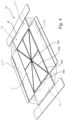
Figure 1 discloses a first layer of a blank configured to form a package. -
Figure 2 discloses the first layer of the blank with a bottom layer insert thereon. -
Figure 3 disclose the first layer of the blank with the bottom layer insert with grooves and a polymer-based film thereon. -
Figure 4 discloses a blank with a bottom layer insert and a polymer-based film attached to the blank. -
Figure 5 discloses a blank being folded into a package. -
Figure 6 discloses the finally formed package. -
Figure 7 is a cross-sectional view along line VII-VII inFig 6 . -
Figures 8a-b discloses two embodiments of a bottom layer insert. - The preferred embodiment according to the disclosure will be explained in detail in combination with the drawing below. Those skilled in the art will further understand the characteristics and the advantages through the drawings and the corresponding literal description. Obviously, the described embodiments are a part of the embodiment of the disclosure, but not all of them. The components of the embodiment of the disclosure described and shown in the drawings here can be arranged and designed according to various different configurations.
- In the description of the disclosure, the orientations and the position relationship indicated by the terms "top", "bottom", "upper" and "lower", etc. are those based on what are shown in the drawing, or the orientations and the position relationship when the product of the disclosure is commonly placed, which is merely for convenience of the description of the disclosure and of simplifying the description, but does not indicate or imply the device or the element has to be have particular orientation, or to be constructed or operated in an particular orientation, and thus cannot be understood as limiting on the disclosure. Herefore, the detailed description of the embodiment of the disclosure provided in combination with the drawing does not aim to limiting the protection scope of the disclosure, and is only the selected embodiment of the disclosure. Based on the embodiment of the disclosure, all the other embodiments obtained by those skilled in the art without any creative work would belong to the protection scope of the disclosure.
- With reference to
Figs 1-4 , there is disclosed a blank 10 comprising afirst layer 20 of a paper-based material and a second layer of a paper-based material and a polymer-basedfilm 40. The first layer comprises abottom panel 21 and a plurality ofside wall panels 22a-d. - With reference to
Fig 1 . thefirst layer 20 of paper-based material of the blank 10 is shown in a flat laid state. Thefirst layer 20 comprises arectangular bottom panel 21 and four side walls 22 a-d at a respective side of thebottom panel 21. It is noted that the bottom panel can have any shape. The blank 10 has crease lines to guide and facilitate the folding of the blank to a package. Thebottom panel 21 has a major surface area. The four side walls 22 a-d may have different shapes. The side walls can be less than or more than four. Preferably the number of side walls 22 a-d is the same as the number of edges of thebottom panel 21. There is preferably at least one side wall at each edge of the bottom panel, even though there can be more than one side wall, such as two, three or more side walls 22 a-d on a single edge of thebottom panel 21. The four side walls 22 a-d are foldably connected to the bottom panel and configured to be folded upwardly. - The paper-based material is preferably a corrugated board. The flute types of the corrugated board may vary from N to C and could also be double walled such as E/B or other suitable combinations as well. This is applicable for any paper-based layer discussed herein.
- With reference to
Fig 2 , there is disclosed a blank 10 comprising thefirst layer 20 as shown inFig 1 and thesecond layer 30 of a paper-based material comprising abottom panel insert 31. Thesecond layer 30 may further comprise additional layers. The additional layers may be paper-based or polymer-based, such as being a thin coating on either one, or a plurality of sides such as all sides. Thebottom panel insert 31 has threegrooves 33 extending in three different directions. Alternatively, it may be expressed as that there are six different grooves being pair-wise parallel to each other and all meeting in a central junction. From the context it is understood that there can be no grooves, one groove or a plurality of grooves in thebottom layer insert 31. Thegrooves 33 may vary in width, depth, shape, i.e., being straight or curved, and direction. The width or depth can vary independently of each other along a direction of thegrooves 33. When there are several grooves, the grooves may intersect preferably in a central part of thebottom panel insert 31. In an embodiment withseveral groove 33, the grooves may be non-intersecting. The grooves can be formed from creasing, die cutting or any other suitable technique to make grooves in a paper-based material. The bottom panel insert is placed on top of an intended interior surface of thebottom panel 21. Thebottom panel insert 31 may be located directly or indirectly on top of an interior surface of thebottom panel 21. The thickness of the bottom layer insert may be more than 2 mm, preferably more than 4 mm The material may e.g., be 2-8mm. Thebottom panel insert 31 has a surface area smaller than a surface area of thebottom panel 21 such that, when theside wall panels 22a-d are folded upwardly relative to thebottom panel 21, one ormore channels 23 are formed around at least a part of a perimeter of thebottom panel insert 31. Preferably at least one channel is formed at each side of thebottom panel insert 31. Even more preferably one continuous channel is formed more or less, preferably completely, around the entirety of the perimeter of the bottom panel insert. Preferably the depths of the channels are greater than the depth of the grooves. In the preferred embodiment the grooves are connected to the channel. Preferably, all grooves are directly or indirectly connected to a channel. Preferably all channels are connected to at least one groove. - With reference to
Fig 3 , t the blank 10 is provided with a polymer-basedfilm 40 being positioned on top of the first and second paper-based layers. The thickness of the polymer-basedfilm 40 is preferably 30-90 µm, and more preferably 60-90 µm. A polymer-based film of such thickness is typically sufficiently flexible to be easily folded, but still strong enough to allow the polymer-based film to easily be peeled off from the paperboard blank. The polymer-basedfilm 40 may e.g., be provided on a roll where a part of the film is rolled out of the roll and stretch out on top of the paper-based layers. It is also conceivable that the polymer-basedfilm 40 is provided in sheets. The polymer-based film may be based on polyethylene terephthalate (PET), polyethylene terephthalate glycol modified (PETG), polypropylene (PP), polyethylene (PE), polyamide (PA), or any other suitable polymer. The polymer-basedfilm 40 extends or is allowed to extend down into at least part of at least one of the channels. It may be noted that the polymer-based film preferably extends beyond the whole bottom layer such that it covers all of the bottom panel as well as at least parts of some and preferably at least parts of all wall panels. The polymer-based film may extend into or be allowed to extend down into at least some and preferably into all of said channels such that the polymer-basedfilm 40 has an extension sufficient for it to at least partly and preferably fully follow the shape of thechannels 23 and extend down into thechannels 23. The polymer base film may extend into or be allowed to extend down into at least some and preferably into all of saidgrooves 33 such that the polymer-basedfilm 40 has an extension sufficient for it to at least partly and preferably fully follow the shape of thegrooves 33 and extend down into thegrooves 33. The portions of thefilm 40 which extend down into the grooves and channels are denotedreference numbers Fig. 4 andFig. 5 respectively. - With reference to
Fig 4 , there is disclosed the blank shown inFig 3 with the polymer-basedfilm 40 being attached to theside walls 22a-d at arespective attachment zone 42 extending along an intended upper portion of the respectiveside wall panels 22a-d. It is to be understood that "upper" in terms of theattachment zone 42 refers to upper portions of a folded package resting upright as depicted e.g. inFig. 6 . The upper portion is preferably at a minimum at least a distance away from thebottom panel 21 that is equal or greater than the thickness of thebottom panel insert 31, such that the polymer-based film is attached at a portion being higher than the upper surface of the insert. The polymer-based film is preferably attached to the channels and/or the grooves. It may e.g., be attached to the paper-based layers using adhesive positioned between the polymer-based film and the respective paper-based layer at certain positions through-out the area of the blank; including said upper portionsof the side walls and said channels and grooves. In the preferred embodiment, the polymer-based film is attached to the respective paper-based layer using a heat sealing operation, such as a thermo-forming operation, where inherent heat sealing properties of the polymer-based film are utilized to attach the polymer-based film to the respective paper-based layer. The overall attachment of the polymer-based film is preferably performed such that thebottom panel insert 31 is held in place on top of thebottom layer 21. In the preferred embodiment the polymer-basedfilm 40 is attached inside of all channels and allgrooves 33, which will aid in securing that the bottom panel insert is held in place. The polymer-based film may be attached to the respective paper-based layer over the complete surface area where the polymer-based film is present on top of any of the first and/or second paper-based layers or the polymer-based film may be attached to the respective paper-based layer only at select positions. The select positions may e.g., be said upper portions of the side wall. The select positions may also include all or parts of the bottoms of the channels. -
Fig 5 shows the blank 10 being folded into a package. In the disclosed design two of the opposingside wall panels top wall panels 22e-f. Thetop wall panels 22e-f are in turn provided with lockingpanels 22g-j. Thetop wall panels 22e-f are folded inwardly relative to the respectiveside wall panel panels 22g-j are folded downwardly relative to thetop wall panels 22e-f such that the lockingpanels 22g-j ends up on a respective outside portion of the other opposingside walls panels 22g-j are e.g., adhesively connected to theside walls layer 20 of the blank 10 may be basically any kind of otherwise known package as long as it allows for a folding into a package such that the polymer-basedlayer 40 is allowed to form a continuous inside surface of the package - With reference to
Fig 6 a package formed from the blank is disclosed. - With reference to
Fig 7 it is disclosed a cross section of the package shown inFig 6 . - With reference to
Fig 8a and 8b variations of the bottom panel insert is shown. The grooves can be formed by a crease being formed in an uppermost layer of thebottom panel insert 31, and/or by a cut being formed in an uppermost layer, or a plurality of uppermost layers, of thebottom panel insert 31. Thebottom panel insert 31 may e.g., be formed of a corrugated paper material having more than one flute layers. A set of cuts may be provided in the uppermost flat layer and through one or more of the uppermost flute layers and the cut layers may be crushed such that the flutes collapse and adistinct groove 33 is formed. This may e.g., be performed in a conventional die cut machine. Alternatively, thebottom panel insert 31 may be formed of a plurality of layers of paper-based material being positioned or folded on top of each other such that there is formed grooves. It is e.g., possible to have a rectangular centre panel with triangular flaps extending outwardly. The triangular flaps may in total have a slightly smaller size than the centre panel such that as the triangular flaps are folded onto the centre panel, there is formed a diagonal cross of grooves between the triangular flaps. - It is contemplated that there are numerous modifications of the embodiments described herein, which are still within the scope of the invention as defined by the appended claims.
- Additionally, variations to the disclosed embodiments can be understood and effected by the skilled person in practicing the claimed invention, from a study of the drawings, the disclosure, and the appended claims. In the claims, the word "comprising" does not exclude other elements or steps, and the indefinite article "a" or "an" does not exclude a plurality. The mere fact that certain measures are recited in mutually different dependent claims does not indicate that a combination of these measured cannot be used to advantage.
Claims (12)
- Blank (10) configured to be folded into a package (50), the blank (10) comprisinga first layer (20) of a paper-based material which comprisesa bottom panel (21) anda plurality of side wall panels (22a-d),a second layer (30) of a paper-based material comprisinga bottom panel insert (31) on top of an intended interior surface of the bottom panel (21),wherein the bottom panel insert (31) has a surface area smaller than a surface area of the bottom panel (21) of the first layer such that, when the side wall panels (22a-d) are folded upwardly relative to the bottom panel (21), one or more channels (23) are formed around at least a part of a perimeter of the bottom panel insert (31),a polymer-based film (40) being positioned on top of the first and second paper-based layers and being attached to at least two opposing side wall panels (22a-d) at at least a respective attachment zone (42) extending along an intended upper portion of the respective one of the two side wall panels (22a-d) with the polymer-based film (40) extending, or being allowed to, extend down into at least some, and preferably into all, of said channels (23).
- Blank (10) according to claim 1 wherein the bottom panel insert (31) is provided with at least one groove (33) in an upper surface thereof with the polymer-based film (40) extending, or being allowed to extend, down into at least some and preferably all of said grooves (33).
- Blank (10) according to claim 1 or 2, wherein the bottom panel insert (31) is provided with a plurality of grooves (33) with the polymer-based film (40) extending, or being allowed to extend, down into at least some and preferably all of said grooves (33).
- Blank (10) according to claim 2 or 3, wherein a depth of at least one of the channels (23) around the perimeter of the bottom panel insert (31) is greater than a depth of the groove (33) in the bottom panel insert (31).
- Blank (10) according to any one of claims 2-4, wherein the groove or grooves (33) of the bottom panel insert (31) is/are connected with at least one of said channels (23).
- Blank (10) according to any one of the preceding claims, wherein the polymer-based film (40) is a liquid-tight polymer-based film.
- Blank (10) according to any one of the preceding claims, wherein the polymer-based film (40) is attached, at least partly, to at least one of said channels (23).
- Blank (10) according to any one of claims 4-6 when dependent upon claim 2 or 3, wherein the polymer-based film (40) is attached, at least partly, to at least one of the grooves (33).
- Blank (10) according to any preceding claims wherein the polymer-based film (40) is attached to all side wall panels (22a-d) at at least a respective attachment zone extending along an intended upper portion of the respective side wall panel (22a-d).
- Blank (10) according to any one of the preceding claims, wherein the bottom panel insert (31) is positioned such that the channel (23) is formed at at least two opposite sides of the bottom panel insert.
- Blank (10) according to any one of the preceding claims, wherein the bottom panel insert (31) is positioned such that the channel (23) is formed at all sides of the bottom panel insert (31).
- Package (50) formed of a blank (10) comprising:A blank (10),Wherein the blank (10) comprises:a first layer (20) of paper-based material which comprises a bottom panel (21) and a plurality of side wall panels (22a-d),a second layer (30) of a paper-based material comprising:a bottom panel insert (31) on top of an interior surface of the bottom panel (21),wherein the bottom panel insert (31) has a surface area smaller than a surface area of the bottom panel (21) of the first layer such that one or mor channels (23) are formed around at least a part of a perimeter of the bottom panel insert (31),and a polymer-based film (40) being positioned on top of the first and second paper-based layers (20, 30) and being attached to at least two opposing side wall panels (22a-d) at at least a respective attachment zone extending along an upper portion of the respective one of the two side wall panels (22a-d) with the polymer-based film (40) extending or being allowed to extend down into at least some and preferably all of said channels (23).
Applications Claiming Priority (1)
| Application Number | Priority Date | Filing Date | Title |
|---|---|---|---|
| SE2330483A SE548003C2 (en) | 2023-10-31 | 2023-10-31 | Blank and a package |
Publications (1)
| Publication Number | Publication Date |
|---|---|
| EP4549333A1 true EP4549333A1 (en) | 2025-05-07 |
Family
ID=93289054
Family Applications (1)
| Application Number | Title | Priority Date | Filing Date |
|---|---|---|---|
| EP24208858.1A Pending EP4549333A1 (en) | 2023-10-31 | 2024-10-25 | Blank and a package |
Country Status (2)
| Country | Link |
|---|---|
| EP (1) | EP4549333A1 (en) |
| SE (1) | SE548003C2 (en) |
Citations (6)
| Publication number | Priority date | Publication date | Assignee | Title |
|---|---|---|---|---|
| EP0442720A1 (en) | 1990-02-15 | 1991-08-21 | W.R. Grace & Co.-Conn. | Lined container and method of making same |
| WO2007091004A1 (en) | 2006-02-09 | 2007-08-16 | Alexir Packaging Limited | Foldable container |
| WO2007139978A2 (en) * | 2006-05-26 | 2007-12-06 | Hirschey Urban C | Carton assembly having a waterproof lining |
| KR20100052013A (en) * | 2008-11-10 | 2010-05-19 | 이정혁 | A pakaging paper box for frozen food |
| WO2018093586A1 (en) * | 2016-11-17 | 2018-05-24 | Westrock Shared Services, Llc | Food packaging insert and system |
| KR20220064256A (en) * | 2020-11-11 | 2022-05-18 | 주식회사 퓨처키친 | Food packaging box |
Family Cites Families (3)
| Publication number | Priority date | Publication date | Assignee | Title |
|---|---|---|---|---|
| US3515331A (en) * | 1968-09-09 | 1970-06-02 | Clifton W Guthrie Sr | Carton construction |
| FR2645831B1 (en) * | 1989-04-12 | 1991-08-30 | Socar | NEW WRAPPED PACKAGING, WATERPROOF, OPTIONALLY SEALABLE WITH A THERMOPLASTIC FILM |
| WO1995035204A1 (en) * | 1994-06-20 | 1995-12-28 | Newark Group Industries, Inc. | Method for forming corrugated paper container and container made therefrom |
-
2023
- 2023-10-31 SE SE2330483A patent/SE548003C2/en unknown
-
2024
- 2024-10-25 EP EP24208858.1A patent/EP4549333A1/en active Pending
Patent Citations (6)
| Publication number | Priority date | Publication date | Assignee | Title |
|---|---|---|---|---|
| EP0442720A1 (en) | 1990-02-15 | 1991-08-21 | W.R. Grace & Co.-Conn. | Lined container and method of making same |
| WO2007091004A1 (en) | 2006-02-09 | 2007-08-16 | Alexir Packaging Limited | Foldable container |
| WO2007139978A2 (en) * | 2006-05-26 | 2007-12-06 | Hirschey Urban C | Carton assembly having a waterproof lining |
| KR20100052013A (en) * | 2008-11-10 | 2010-05-19 | 이정혁 | A pakaging paper box for frozen food |
| WO2018093586A1 (en) * | 2016-11-17 | 2018-05-24 | Westrock Shared Services, Llc | Food packaging insert and system |
| KR20220064256A (en) * | 2020-11-11 | 2022-05-18 | 주식회사 퓨처키친 | Food packaging box |
Also Published As
| Publication number | Publication date |
|---|---|
| SE2330483A1 (en) | 2025-05-01 |
| SE548003C2 (en) | 2026-01-07 |
Similar Documents
| Publication | Publication Date | Title |
|---|---|---|
| EP3894329B1 (en) | Product package and method of manufacturing the same as well as package blank | |
| EP1578672B1 (en) | Container | |
| US20170166384A1 (en) | Container with absorption features | |
| US3756495A (en) | Boilable bakeable package | |
| ES2626972T3 (en) | Packaging system comprising a cardboard structure | |
| US20080041860A1 (en) | Three-layered containers and methods of making the same | |
| WO2022264022A1 (en) | Container comprising an outer skeleton and an inner layer of thermoplastic material and method for making it | |
| MX2012006089A (en) | Bags having adhesive drying structures and related methods. | |
| US12545470B2 (en) | Container with independent reinforcement frame | |
| GB2546189A (en) | Container | |
| IL211719A (en) | Flexible packaging container having a bag insert | |
| WO2025042681A1 (en) | Container with divider | |
| CA3028816A1 (en) | Container with edge protection features | |
| JP4736515B2 (en) | Flanged partition tray container and manufacturing method thereof | |
| JP2008501588A (en) | Containers, blanks and methods made from laminate materials | |
| MX2007010153A (en) | Three-layered containers and methods of making the same. | |
| CN1902097A (en) | A child resistant carton package | |
| US11124350B2 (en) | Container configured to collect and retain fluid shed from container contents | |
| CA2988527C (en) | Container with oleophilic/oleophobic pattern on a sealing surface | |
| KR20060051382A (en) | Tray-shaped container of flexible material and related manufacturing method and apparatus | |
| EP4194354A1 (en) | Folded cardboard container | |
| SE523133C2 (en) | Packaging, primarily intended for food | |
| US20230105561A1 (en) | Insulating packaging for crustaceans | |
| CN218490154U (en) | Packaging container | |
| JP7757015B2 (en) | Assembled paper container manufacturing method and assembled paper container manufacturing device |
Legal Events
| Date | Code | Title | Description |
|---|---|---|---|
| PUAI | Public reference made under article 153(3) epc to a published international application that has entered the european phase |
Free format text: ORIGINAL CODE: 0009012 |
|
| STAA | Information on the status of an ep patent application or granted ep patent |
Free format text: STATUS: THE APPLICATION HAS BEEN PUBLISHED |
|
| AK | Designated contracting states |
Kind code of ref document: A1 Designated state(s): AL AT BE BG CH CY CZ DE DK EE ES FI FR GB GR HR HU IE IS IT LI LT LU LV MC ME MK MT NL NO PL PT RO RS SE SI SK SM TR |
|
| STAA | Information on the status of an ep patent application or granted ep patent |
Free format text: STATUS: REQUEST FOR EXAMINATION WAS MADE |
|
| 17P | Request for examination filed |
Effective date: 20251107 |
|
| GRAP | Despatch of communication of intention to grant a patent |
Free format text: ORIGINAL CODE: EPIDOSNIGR1 |
|
| STAA | Information on the status of an ep patent application or granted ep patent |
Free format text: STATUS: GRANT OF PATENT IS INTENDED |
|
| INTG | Intention to grant announced |
Effective date: 20260603 |