EP4549281A1 - Rear cover assembly for an axle box of a railcar bogie, wheelset, bogie, and railway vehicle comprising such rear cover assembly - Google Patents
Rear cover assembly for an axle box of a railcar bogie, wheelset, bogie, and railway vehicle comprising such rear cover assembly Download PDFInfo
- Publication number
- EP4549281A1 EP4549281A1 EP23306909.5A EP23306909A EP4549281A1 EP 4549281 A1 EP4549281 A1 EP 4549281A1 EP 23306909 A EP23306909 A EP 23306909A EP 4549281 A1 EP4549281 A1 EP 4549281A1
- Authority
- EP
- European Patent Office
- Prior art keywords
- rear cover
- cover assembly
- axle
- fixing flange
- fixing
- Prior art date
- Legal status (The legal status is an assumption and is not a legal conclusion. Google has not performed a legal analysis and makes no representation as to the accuracy of the status listed.)
- Pending
Links
Images


Classifications
-
- B—PERFORMING OPERATIONS; TRANSPORTING
- B61—RAILWAYS
- B61F—RAIL VEHICLE SUSPENSIONS, e.g. UNDERFRAMES, BOGIES OR ARRANGEMENTS OF WHEEL AXLES; RAIL VEHICLES FOR USE ON TRACKS OF DIFFERENT WIDTH; PREVENTING DERAILING OF RAIL VEHICLES; WHEEL GUARDS, OBSTRUCTION REMOVERS OR THE LIKE FOR RAIL VEHICLES
- B61F1/00—Underframes
Definitions
- the present invention relates to a rear cover assembly for an axle box of a railcar bogie, and to a wheelset, a bogie and a railway vehicle comprising such rear cover assembly.
- the present invention is particularly suitable for being used in railway vehicles train which are using elastic or resilient wheels, such as trams, and will be described hereinafter by making particular reference to such application, without intending in any way to limit its possible use in other types of railway vehicles.
- railway vehicles such as trams
- bogies that include a certain number of wheelsets.
- Each wheelset comprises an axle on which there mounted the wheels, and each wheel is associated to an axle box which is mounted on the axle externally to and close to the associated wheel.
- axle box On the axle there are mounted others components, and in particular a front cover which is positioned on the side of the axle box opposite to the wheel, and a rear cover which is positioned between the wheel and the axle box bearing.
- the front and rear covers are screwed or bolted to the axle box to maintain the axial position and ensure tightness of the axle box itself.
- a rear cover assembly for an axle box cover assembly for an axle box of a railcar bogie the axle box being coupled to an axle on which there is mounted at least one wheel and at least one replaceable component which is coupled to the at least one wheel
- the rear cover assembly being characterized in that it comprises at least:
- transversal or transversally when hereby used, they have to be understood as encompassing a direction non-parallel to the reference part(s) or direction(s)/axis they refer to, and perpendicularity has to be considered a specific case of transverse direction.
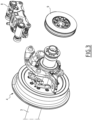
- Figures 1 and 2 show the components of a rear cover assembly according to the invention, indicated by the overall number 1, for an axle box 2 of a railcar bogie, which are under assembly and assembled and connected to the axle box 2, respectively.
- the at least one replaceable component is a sacrificial component that is purposively provided for wearing during operations and that needs to be maintained or replaced after a certain amount of work.
- the at least one replaceable component can comprise for instance a wheel rim 5, and/or a wheel pressing ring 6, and/or a rubber ring 5B, replaceable by removing the wheel rim 5.
- the wheel rim 5 has an inner diameter D1
- the wheel pressing ring 6 has an inner diameter D2
- the rubber ring 5B has an inner diameter D3.
- the end surface 2A is typically the face of the axle box 2 facing the wheel 4.
- the rear cover 10 is configured to allow dismounting said at least one replaceable component 5, 5B and 6 from the axle 3 while keeping the rear cover 10 itself around the axle 3.
- the rear cover 10 is constituted by a body made of a single metallic piece which is ring-shaped.
- the ring-shaped body of the rear cover 10 has an outer diameter, indicated in figure 2 by the reference D4 which is smaller than the inner diameter D1 of the at least one replaceable component or of each inner diameters D1, D2 and D3 of the replaceable components 5, 5B and 6.
- the rear cover assembly 1 comprises two fixing flanges, namely the first fixing flange 11 and a second fixing flange 12 which are positioned at and removably connected to two corresponding opposite parts of the rear cover 10.
- the first connecting means comprise:
- the second connecting means comprise:
- the at least one fixing flange 11 or each of the first and second fixing flanges 11, 12 comprises a first portion 18 which has a circular sector shape arranged to be positioned at and bear against an associated external side portion of the rear cover 10, and one or more protuberances 19 which extends from the first portion 18 in a direction substantially parallel to the axle 3 which are provided each with a corresponding fixing hole 16.
- first fixing flange 11 and the second fixing flange 12 are connected to two corresponding opposite parts of the rear cover 10 and are positioned substantially symmetrically to each other with respect to a vertical axis, as indicated by the capital letter Y in the exemplary embodiment illustrated in figure 2 , or with respect to a horizontal axis which substantially transversal to the axial direction of extension of the axle 3.
- first fixing flange 11 and the second fixing flange 12 are substantially identical to each other and are made each of a single metallic piece.
- the at least one flange 11 or both the first and second fixing flanges 11 and 12 are assembled together by positioning the two flanges 11 and 12 bearing against two opposite sides of the rear cover 10 so as to substantially align each passing through hole 14 with a corresponding blind hole 13. Then, each screw 15 is inserted into a corresponding passing through hole and screwed into the respective blind hole 13.
- the assembly thus obtained is fixed to the end surface 2A of the axle box 2 via the plurality of fasteners 17 each of which is passed into a through hole 7 of the axle box and is fastened into a corresponding blind hole.
- wheel rim 5, and/or the rubber ring 5B, and the wheel pressing ring 6 can be extracted out from the axle passing them over the rear cover 10 as illustrated in figure 6 .
- the rear cover assembly 1 allows achieving the intended aim since it allows to realize maintenance operations where a reduced number of components need to be removed with respect to known solutions.
- the rear cover assembly 1 thus conceived is susceptible of modifications and variations, all of which are within the scope of the inventive concept as defined in particular by the appended claims; for example, in relation to the specific application, it is possible to use only one fixing flange, e.g. U or C- shaped, or more than two fixing flanges.
- the or each fixing flange can be differently shaped with respect to the exemplary embodiments previously described, provided that such shape is compatible and suitable for the functionalities required within the frame of the present invention.
Landscapes
- Engineering & Computer Science (AREA)
- Mechanical Engineering (AREA)
- Connection Of Plates (AREA)
Abstract
- a rear cover (10);
- at least one fixing flange (11, 12);
- first connecting means (13, 14, 15) for removably connecting the at least one fixing flange (11, 12) to the rear cover (10); and
- second connecting means (16, 17) for removably connecting the at least one fixing flange (11, 12) to an end surface (2A) of the axle box (2) with the rear cover (10) being positioned around the axle (3) and held in place between said end surface (2A) of the axle box (2) and the at least one fixing flange (11, 12).
Description
- The present invention relates to a rear cover assembly for an axle box of a railcar bogie, and to a wheelset, a bogie and a railway vehicle comprising such rear cover assembly.
- The present invention is particularly suitable for being used in railway vehicles train which are using elastic or resilient wheels, such as trams, and will be described hereinafter by making particular reference to such application, without intending in any way to limit its possible use in other types of railway vehicles.
- As known, railway vehicles, such as trams, comprise bogies that include a certain number of wheelsets.
- Each wheelset comprises an axle on which there mounted the wheels, and each wheel is associated to an axle box which is mounted on the axle externally to and close to the associated wheel.
- On the axle there are mounted others components, and in particular a front cover which is positioned on the side of the axle box opposite to the wheel, and a rear cover which is positioned between the wheel and the axle box bearing.
- The front and rear covers are screwed or bolted to the axle box to maintain the axial position and ensure tightness of the axle box itself.
- This is a common and regular assembly found on most railway rolling stock fitted with axle boxes.
- At present, although the configuration of known rear covers allows properly performing the required task, it still presents some aspects worth of improvements.
- In particular, in known solutions, when there is a need to carry out maintenance and for example to replace wearable components associated with the wheels, such as the so-called wheel steel tires or rims, rubber rings or resilient bushings, it is necessary to basically dismount from the axle the entire assembly, namely the bearing of the axle box, and other components, such as a brake disc hub, the same rear cover, et cetera.
- This poses a number of issues, namely the removal of components can damage the axle or the components themselves, in which case they have to be replaced.
- Further, these operations are time-consuming, costly and require the use of special machinery and skills.
- Therefore, the present invention is aimed at providing a solution that allows at least mitigating one or more of the above issues.
- This aim is achieved by a rear cover assembly for an axle box cover assembly for an axle box of a railcar bogie, the axle box being coupled to an axle on which there is mounted at least one wheel and at least one replaceable component which is coupled to the at least one wheel, the rear cover assembly being characterized in that it comprises at least:
- a rear cover which has a ring shaped body;
- at least one fixing flange;
- first connecting means for removably connecting the at least one fixing flange to the rear cover; and
- second connecting means for removably connecting the at least one fixing flange to an end surface of the axle box with the rear cover being positioned around the axle and held in place between said end surface of the axle box and the at least one fixing flange.
- This aim is also achieved by a wheelset for a bogie or a railcar, a bogie for a railcar, and a railway vehicle or car, notably a tram, comprising a rear cover assembly as above defined, and in particular as better described hereinafter and defined in more details in the appended claims.
- Further characteristics and advantages will become apparent from the description of some preferred but not exclusive exemplary embodiments of a rear cover assembly according to the present disclosure, illustrated only by way of non-limitative examples with the accompanying drawings, wherein:
-
Figure 1 is a perspective view schematically showing an exemplary embodiment of a rear cover assembly according to the invention, under assembling; -
Figure 2 is a perspective view schematically showing the rear cover assembly offigure 1 assembled and connected to an axle box of a bogie; -
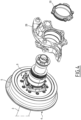
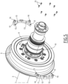
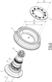
Figures 3 to 6 shows a sequence of dismounting from an axle of a bogie a wheel pressing ring and a wheel rim when there is used a rear cover assembly according to the invention. - It should be noted that in the detailed description that follows, identical or similar components, either from a structural and/or functional point of view, may have the same or different reference numerals, regardless of whether they are shown in different embodiments of the present disclosure; it should also be noted that in order to clearly and concisely describe the present disclosure, the drawings may not necessarily be to scale and certain features of the disclosure may be shown in somewhat schematic form.
- Further, when the term "arranged", or "configured", or "shaped", or a similar term is used herein while referring to any component as a whole, or to any part of a component, or to a combination of components, it has to be understood that it means and encompasses correspondingly either the structure, and/or the configuration, and/or the form, and/or the positioning.
- In addition, when the term "about" or "substantial" or "substantially" is used herein, it has to be understood as encompassing unavoidable mechanical differences/tolerances, or an actual variation of plus or
minus 5% with respect to an indicated reference value or position. - Further, when the terms transversal or transversally are hereby used, they have to be understood as encompassing a direction non-parallel to the reference part(s) or direction(s)/axis they refer to, and perpendicularity has to be considered a specific case of transverse direction.
-
Figures 1 and2 show the components of a rear cover assembly according to the invention, indicated by the overall number 1, for an axle box 2 of a railcar bogie, which are under assembly and assembled and connected to the axle box 2, respectively. - According to solutions well known in the art or in any case readily available to those skilled in the art, the axle box 2 is coupled to an
axle 3 on which there is mounted at least onewheel 4 and at least one replaceable component which is coupled to the at least onewheel 4. - For example, the at least one replaceable component is a sacrificial component that is purposively provided for wearing during operations and that needs to be maintained or replaced after a certain amount of work.
- In particular, as better visible in
figure 6 , the at least one replaceable component has a substantially circular shape or in any case at least one substantially circular inner shape, having a predefined inner diameter. - The at least one replaceable component can comprise for instance a
wheel rim 5, and/or a wheel pressingring 6, and/or arubber ring 5B, replaceable by removing thewheel rim 5. - As indicated in
figure 6 , thewheel rim 5 has an inner diameter D1, the wheel pressingring 6 has an inner diameter D2, and therubber ring 5B has an inner diameter D3. - As illustrated in
figure 1 , the rear cover assembly 1 according to the invention comprises at least: - a
rear cover 10 which has a ring shaped body; - at least one
fixing flange 11; - first connecting means for removably connecting the at least one
fixing flange 11 to therear cover 10; and - second connecting means for removably connecting the at least one
fixing flange 11 to anend surface 2A of the axle box 2 with therear cover 10 being positioned around theaxle 3 and held in place between saidend surface 2A of the axle box 2 and the at least onefixing flange 11. - The
end surface 2A is typically the face of the axle box 2 facing thewheel 4. - In particular, in the rear cover assembly 1 according to the invention, the
rear cover 10 is configured to allow dismounting said at least onereplaceable component axle 3 while keeping therear cover 10 itself around theaxle 3. - In one possible embodiment, the
rear cover 10 is constituted by a body made of a single metallic piece which is ring-shaped. - Conveniently, in the rear cover assembly 1 according to the invention, the ring-shaped body of the
rear cover 10 has an outer diameter, indicated infigure 2 by the reference D4 which is smaller than the inner diameter D1 of the at least one replaceable component or of each inner diameters D1, D2 and D3 of thereplaceable components - In one possible embodiment, as illustrated in the attached figures, the rear cover assembly 1 comprises two fixing flanges, namely the
first fixing flange 11 and asecond fixing flange 12 which are positioned at and removably connected to two corresponding opposite parts of therear cover 10. - In one possible embodiment, as illustrated in the attached figures, the first connecting means comprise:
- a plurality of
blind holes 13 which are provided on the at least onefixing flange 11 or on each of the first andsecond fixing flanges - a plurality of through
holes 14 provided on therear cover 10; and - a plurality of
screws 15 which are suitable each to be passed into a passing throughhole 14 and screwed into a correspondingblind hole 13. - In one possible embodiment, as illustrated in the attached figures, the second connecting means comprise:
- a plurality of fixing holes 16 (see
figures 4 and5 ) which are provided on the at least onefixing flange 11 or on each of the first andsecond fixing flanges - a plurality of
fasteners 17, such as bolts, screws, suitable to be passed each through an associated throughhole 7 provided at saidend surface 2A of the axle box 2 and to be fastened into acorresponding fixing hole 16. - In one possible embodiment, the at least one
fixing flange 11 or each of the first andsecond fixing flanges first portion 18 which has a circular sector shape arranged to be positioned at and bear against an associated external side portion of therear cover 10, and one ormore protuberances 19 which extends from thefirst portion 18 in a direction substantially parallel to theaxle 3 which are provided each with acorresponding fixing hole 16. - In particular, in one possible embodiment, the
first fixing flange 11 and thesecond fixing flange 12 are connected to two corresponding opposite parts of therear cover 10 and are positioned substantially symmetrically to each other with respect to a vertical axis, as indicated by the capital letter Y in the exemplary embodiment illustrated infigure 2 , or with respect to a horizontal axis which substantially transversal to the axial direction of extension of theaxle 3. - In one possible embodiment, the
first fixing flange 11 and thesecond fixing flange 12 are substantially identical to each other and are made each of a single metallic piece. - In practice, when the rear cover assembly 1 has to installed on a wheelset of a bogie, the at least one
flange 11 or both the first andsecond fixing flanges flanges rear cover 10 so as to substantially align each passing throughhole 14 with a correspondingblind hole 13. Then, eachscrew 15 is inserted into a corresponding passing through hole and screwed into the respectiveblind hole 13. - Then, the assembly thus obtained is fixed to the
end surface 2A of the axle box 2 via the plurality offasteners 17 each of which is passed into a throughhole 7 of the axle box and is fastened into a corresponding blind hole. - When instead there is a need for maintenance, for example in order to replace one or more replaceable components, such as the
wheel rim 5 and/or therubber ring 5B by removing the wheel pressingring 6, once the relevant wheelset is removed from the bogie, then, as illustrated infigure 3 , thecaliper 8 and thedisc ring 9 are removed from theaxle 3. - Thereafter, as illustrated in
figure 4 , thefront cover 30 and thehousing 2B of the axle box 2 are removed, while other components that in prior art solutions need to be dismounted and taken off from theaxle 3, such as thebrake disc hub 31 and the axle box bearing 32, remain fitted around theaxle 3 in their mounted position. - Then, the
fasteners 17 and the screws 15 (seefigure 5 ) are removed, and the at least oneflange 11 or both the first andsecond fixing flanges rear cover 10 can be left in position around theaxle 3. - Finally, the
wheel rim 5, and/or therubber ring 5B, and the wheel pressingring 6 can be extracted out from the axle passing them over therear cover 10 as illustrated infigure 6 . - Hence, it is evident from the foregoing description that the rear cover assembly 1 according to the present invention allows achieving the intended aim since it allows to realize maintenance operations where a reduced number of components need to be removed with respect to known solutions.
- In this way, maintenance operations are somehow facilitated and time and costs for such interventions are reduced.
- These results are achieved according to a configuration which is simple to be realized and installed, and that can be used in principle in any suitable type of wheelset, bogie, or railway vehicle be each of them a new one, or one already in use and which can be serviced replacing the existing rear cover with the rear cover assembly according to the present invention.
- The rear cover assembly 1 thus conceived is susceptible of modifications and variations, all of which are within the scope of the inventive concept as defined in particular by the appended claims; for example, in relation to the specific application, it is possible to use only one fixing flange, e.g. U or C- shaped, or more than two fixing flanges. The or each fixing flange can be differently shaped with respect to the exemplary embodiments previously described, provided that such shape is compatible and suitable for the functionalities required within the frame of the present invention.
- All the details may furthermore be replaced with technically equivalent elements.
Claims (13)
- Rear cover assembly (1) for an axle box (2) of a railcar bogie, the axle box (2) being coupled to an axle (3) on which there is mounted at least one wheel (4) and at least one replaceable component (5, 5B, 6) which is coupled to the at least one wheel (4), the rear cover assembly (1) being characterized in that it comprises at least:- a rear cover (10) which has a ring shaped body;- at least one fixing flange (11, 12);- first connecting means (13, 14, 15) for removably connecting the at least one fixing flange (11, 12) to the rear cover (10); and- second connecting means (16, 17) for removably connecting the at least one fixing flange (11, 12) to an end surface (2A) of the axle box (2) with the rear cover (10) being positioned around the axle (3) and held in place between said end surface (2A) of the axle box (2) and the at least one fixing flange (11, 12).
- The rear cover assembly (1) according to claim 1, wherein said rear cover (10) is configured to allow dismounting said at least one replaceable component (5, 5B, 6) from the axle (3) while keeping the rear cover (10) itself around the axle (3).
- The rear cover assembly (1) according to claim 1 or 2, wherein said at least one replaceable component (5, 5B, 6) has a substantially circular inner shape having an inner diameter (D1, D2, D3), and wherein the ring-shaped body of the rear cover (10) has an outer diameter (D4) which is smaller than the inner diameter (D1, D2, D3) of said at least one replaceable component.
- The rear cover assembly (1) according to one or more of the previous claims, wherein the at least one fixing flange (11) comprises a first fixing flange (11) and a second fixing flange (12) which are positioned at and removably connected to two corresponding opposite parts of the rear cover (10).
- The rear cover assembly (1) according to claim 4, wherein the first fixing flange (11) and the second fixing flange (12) are connected to two corresponding opposite parts of the rear cover (10) positioned substantially symmetrically to each other with respect to a vertical or horizontal axis transversal to the axial direction of extension the axle (3).
- The rear cover assembly (1) according to claim 4 or 5, wherein the first fixing flange (11) and the second fixing flange (12) are substantially identical to each other and are made each of a single metallic piece.
- The rear cover assembly (1) according to one or more of the previous claims, wherein the first connecting means (13, 14, 15) comprise a plurality of blind holes (13) provided on the at least one fixing flange (11) or on each of the first and second fixing flanges (11, 12), a plurality of through holes (14) provided on said rear cover (10), and a plurality of screws (15) suitable each to be passed into a through hole (14) and screwed into a corresponding blind hole (13).
- The rear cover assembly (1) according to one or more of the previous claims, wherein the second connecting means (16, 17) comprise a plurality of fixing holes (16) provided on the at least one fixing flange (11) or on each of the first and second fixing flanges (12), and a plurality of fasteners (17) suitable to be passed each through an associated through hole (7) provided at said end surface (2A) of the axle box (2) and to be fastened into a corresponding fixing hole (16).
- The rear cover assembly (1) according to one or more of the previous claims, wherein the at least one fixing flange (11) or each of the first and second fixing flanges (11, 12) comprises a first portion (18) which has a circular sector shape arranged to be positioned at and bear against an associated external side portion of the rear cover (10), and one or more protuberances (19) which extends from the first portion (18) in a direction substantially parallel to the axle (3) which are provided each with a corresponding fixing hole (16).
- The rear cover assembly (1) according to one or more of the previous claims, wherein said the rear cover (10) is made of a single metallic piece.
- Wheelset for a railcar bogie, comprising an axle (3), at least one wheel (4) mounted on the axle, an axle box (2) which is mounted at one end of the axle (3) facing to and spaced apart from the at least one wheel (4), and at least one replaceable component (5, 5B ,6) which is connected to the at least one wheel (4), characterized in that it comprises at least one rear cover assembly (1) according to one or more of the previous claims.
- Railcar bogie characterized in that it comprises at least one rear cover assembly (1) according to one or more of the previous claims.
- Railway vehicle characterized in that it comprises at least one rear cover assembly (1) according to one or more of the previous claims.
Priority Applications (1)
| Application Number | Priority Date | Filing Date | Title |
|---|---|---|---|
| EP23306909.5A EP4549281A1 (en) | 2023-11-03 | 2023-11-03 | Rear cover assembly for an axle box of a railcar bogie, wheelset, bogie, and railway vehicle comprising such rear cover assembly |
Applications Claiming Priority (1)
| Application Number | Priority Date | Filing Date | Title |
|---|---|---|---|
| EP23306909.5A EP4549281A1 (en) | 2023-11-03 | 2023-11-03 | Rear cover assembly for an axle box of a railcar bogie, wheelset, bogie, and railway vehicle comprising such rear cover assembly |
Publications (1)
| Publication Number | Publication Date |
|---|---|
| EP4549281A1 true EP4549281A1 (en) | 2025-05-07 |
Family
ID=88839602
Family Applications (1)
| Application Number | Title | Priority Date | Filing Date |
|---|---|---|---|
| EP23306909.5A Pending EP4549281A1 (en) | 2023-11-03 | 2023-11-03 | Rear cover assembly for an axle box of a railcar bogie, wheelset, bogie, and railway vehicle comprising such rear cover assembly |
Country Status (1)
| Country | Link |
|---|---|
| EP (1) | EP4549281A1 (en) |
Citations (6)
| Publication number | Priority date | Publication date | Assignee | Title |
|---|---|---|---|---|
| GB441836A (en) * | 1934-04-23 | 1936-01-27 | Franz Gross | Wheel construction |
| EP0958984A1 (en) * | 1998-05-18 | 1999-11-24 | Alstom France SA | Railway vehicle bogie |
| DE102016011737A1 (en) * | 2015-09-29 | 2017-03-30 | Patentes Talgo, S.L. | Rail-bound axle assembly |
| CN107757650A (en) * | 2017-11-23 | 2018-03-06 | 中车长春轨道客车股份有限公司 | The EMU power wheel set axle box device of quasi- arrow gauge conversion |
| CN107856693A (en) * | 2017-11-23 | 2018-03-30 | 中车长春轨道客车股份有限公司 | The EMU power wheel set axle box device of quasi- broad gage conversion |
| CN111071280A (en) * | 2018-10-19 | 2020-04-28 | 中车唐山机车车辆有限公司 | Axle box, bogie and rail vehicle |
-
2023
- 2023-11-03 EP EP23306909.5A patent/EP4549281A1/en active Pending
Patent Citations (6)
| Publication number | Priority date | Publication date | Assignee | Title |
|---|---|---|---|---|
| GB441836A (en) * | 1934-04-23 | 1936-01-27 | Franz Gross | Wheel construction |
| EP0958984A1 (en) * | 1998-05-18 | 1999-11-24 | Alstom France SA | Railway vehicle bogie |
| DE102016011737A1 (en) * | 2015-09-29 | 2017-03-30 | Patentes Talgo, S.L. | Rail-bound axle assembly |
| CN107757650A (en) * | 2017-11-23 | 2018-03-06 | 中车长春轨道客车股份有限公司 | The EMU power wheel set axle box device of quasi- arrow gauge conversion |
| CN107856693A (en) * | 2017-11-23 | 2018-03-30 | 中车长春轨道客车股份有限公司 | The EMU power wheel set axle box device of quasi- broad gage conversion |
| CN111071280A (en) * | 2018-10-19 | 2020-04-28 | 中车唐山机车车辆有限公司 | Axle box, bogie and rail vehicle |
Similar Documents
| Publication | Publication Date | Title |
|---|---|---|
| RU161332U1 (en) | RAILWAY VEHICLE TROLLEY ASSEMBLY | |
| JPH09169265A (en) | Truck for monorail vehicle | |
| US9670962B2 (en) | Axlebox comprising split housing parts, vehicle comprising at least one such axlebox and processes | |
| US3926285A (en) | Mounting device for a brake disk | |
| US12172465B2 (en) | Wheel hub and removable bolt ring assembly for air disk braking system | |
| RU161326U1 (en) | RAILWAY VEHICLE TROLLEY ASSEMBLY | |
| US6189456B1 (en) | High capacity axle for railway freight cars | |
| RU161327U1 (en) | RAILWAY VEHICLE TROLLEY ASSEMBLY | |
| US3974780A (en) | Changeable gauge railing truck | |
| CN110962502B (en) | Elastic wheel for railway vehicle, use method of elastic wheel and independent wheel set | |
| EP4294648B1 (en) | Quick change two-piece railroad wheel assembly | |
| EP2230096A1 (en) | Rail vehicle with wheel sound absorber | |
| EP2876020B1 (en) | Backing device, axlebox, vehicle and methods for mounting and dismounting such a backing device | |
| US2244875A (en) | Rear end construction | |
| CN111457036B (en) | Split wheel-mounted brake disc for railway vehicle | |
| US10384694B2 (en) | Bearing unit for an axlebox of a railway vehicle, axlebox, railway vehicle and maintenance process | |
| CA2358153A1 (en) | Truck and trailer hub | |
| CN207683235U (en) | A kind of split type train wheel | |
| CN215204885U (en) | Built-in axle box suspension railway wagon bogie axle assembly | |
| US869514A (en) | Car-wheel. | |
| CN208827488U (en) | A kind of disc type list tire axle unit | |
| SU1191312A1 (en) | Car wheel pair axle | |
| AU2022201418A1 (en) | Universal fit backing ring assembly for railway axles | |
| CN121573024A (en) | A bogie for aerial rail vehicles | |
| GB2205619A (en) | Brakes |
Legal Events
| Date | Code | Title | Description |
|---|---|---|---|
| PUAI | Public reference made under article 153(3) epc to a published international application that has entered the european phase |
Free format text: ORIGINAL CODE: 0009012 |
|
| STAA | Information on the status of an ep patent application or granted ep patent |
Free format text: STATUS: THE APPLICATION HAS BEEN PUBLISHED |
|
| AK | Designated contracting states |
Kind code of ref document: A1 Designated state(s): AL AT BE BG CH CY CZ DE DK EE ES FI FR GB GR HR HU IE IS IT LI LT LU LV MC ME MK MT NL NO PL PT RO RS SE SI SK SM TR |
|
| STAA | Information on the status of an ep patent application or granted ep patent |
Free format text: STATUS: REQUEST FOR EXAMINATION WAS MADE |
|
| 17P | Request for examination filed |
Effective date: 20251107 |
|
| GRAP | Despatch of communication of intention to grant a patent |
Free format text: ORIGINAL CODE: EPIDOSNIGR1 |
|
| STAA | Information on the status of an ep patent application or granted ep patent |
Free format text: STATUS: GRANT OF PATENT IS INTENDED |
|
| INTG | Intention to grant announced |
Effective date: 20251222 |
|
| GRAJ | Information related to disapproval of communication of intention to grant by the applicant or resumption of examination proceedings by the epo deleted |
Free format text: ORIGINAL CODE: EPIDOSDIGR1 |
|
| STAA | Information on the status of an ep patent application or granted ep patent |
Free format text: STATUS: REQUEST FOR EXAMINATION WAS MADE |
|
| GRAP | Despatch of communication of intention to grant a patent |
Free format text: ORIGINAL CODE: EPIDOSNIGR1 |
|
| STAA | Information on the status of an ep patent application or granted ep patent |
Free format text: STATUS: GRANT OF PATENT IS INTENDED |
|
| INTG | Intention to grant announced |
Effective date: 20260224 |
|
| RIN1 | Information on inventor provided before grant (corrected) |
Inventor name: ITASSE, GUILLAUME Inventor name: SARTORI, KEVIN |